Embed Size (px)
Citation preview
Design of embankments on soft soil using
geosynthetics
Lecture 34
Prof. G L Sivakumar BabuDepartment of Civil EngineeringIndian Institute of ScienceBangalore 560012Email: [email protected]
• INTRODUCTION
• MODES OF FAILURE
• STABILITY CONDITION
• DESIGN EXAMPLE
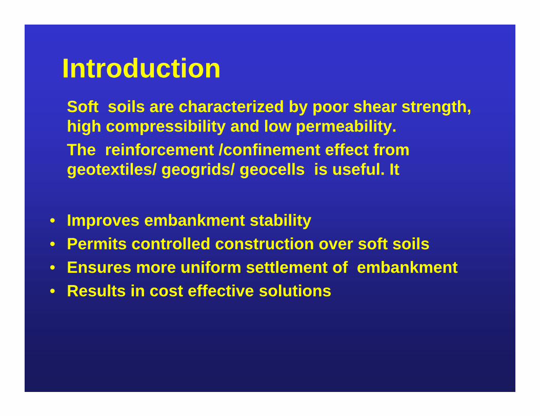
IntroductionSoft soils are characterized by poor shear strength, high compressibility and low permeability.The reinforcement /confinement effect from geotextiles/ geogrids/ geocells is useful. It
• Improves embankment stability• Permits controlled construction over soft soils• Ensures more uniform settlement of embankment• Results in cost effective solutions
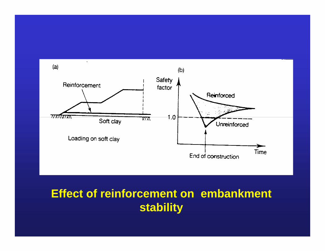
Effect of reinforcement on embankment stability
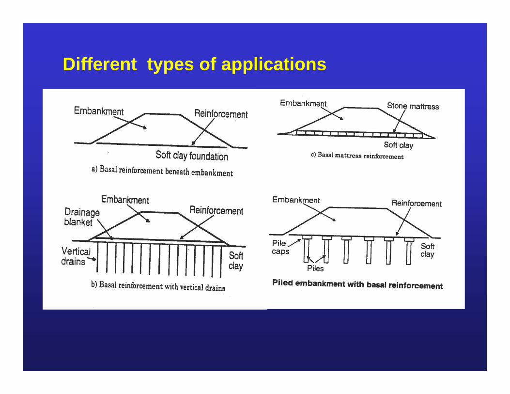
Different types of applications
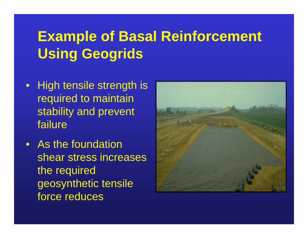
Example of Basal Reinforcement Using Geogrids
• High tensile strength is required to maintain stability and prevent failure
• As the foundation shear stress increases the required geosynthetic tensile force reduces
Analysis and Design
• Established geotechnical and stability methods used
• Three main failure mechanisms considered- Rotational Stability- Lateral Sliding- Bearing Capacity
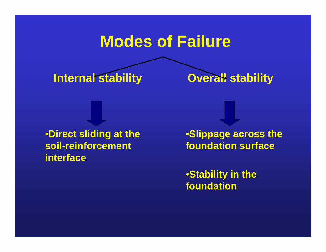
Modes of Failure
Internal stability Overall stability
•Direct sliding at the soil-reinforcement interface
•Slippage across the foundation surface
•Stability in the foundation
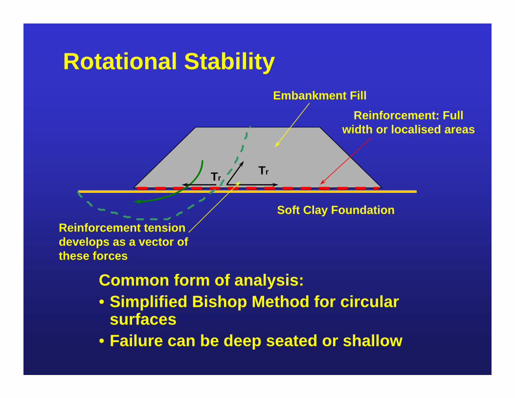
Rotational Stability
Common form of analysis: • Simplified Bishop Method for circular
surfaces• Failure can be deep seated or shallow
Reinforcement: Full width or localised areas
Soft Clay Foundation
Embankment Fill
Reinforcement tension develops as a vector of these forces
TrTr
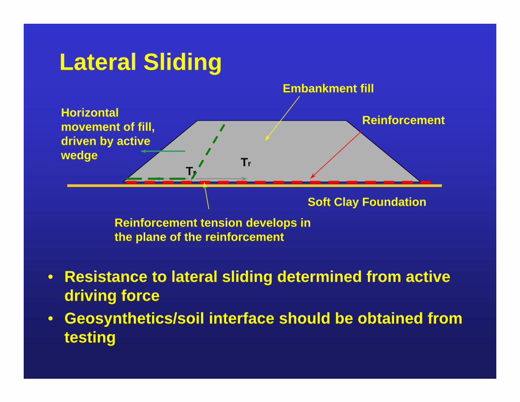
Lateral Sliding
• Resistance to lateral sliding determined from active driving force
• Geosynthetics/soil interface should be obtained from testing
Reinforcement
Soft Clay Foundation
Embankment fill
Reinforcement tension develops in the plane of the reinforcement
TrTr
Horizontal movement of fill, driven by active wedge
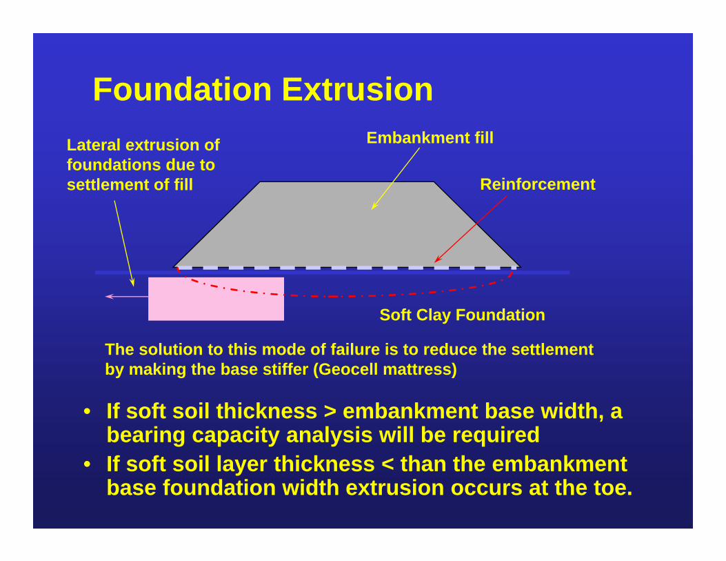
Foundation Extrusion
• If soft soil thickness > embankment base width, a bearing capacity analysis will be required
• If soft soil layer thickness < than the embankment base foundation width extrusion occurs at the toe.
Soft Clay Foundation
Embankment fillLateral extrusion of foundations due to settlement of fill
The solution to this mode of failure is to reduce the settlement by making the base stiffer (Geocell mattress)
Reinforcement
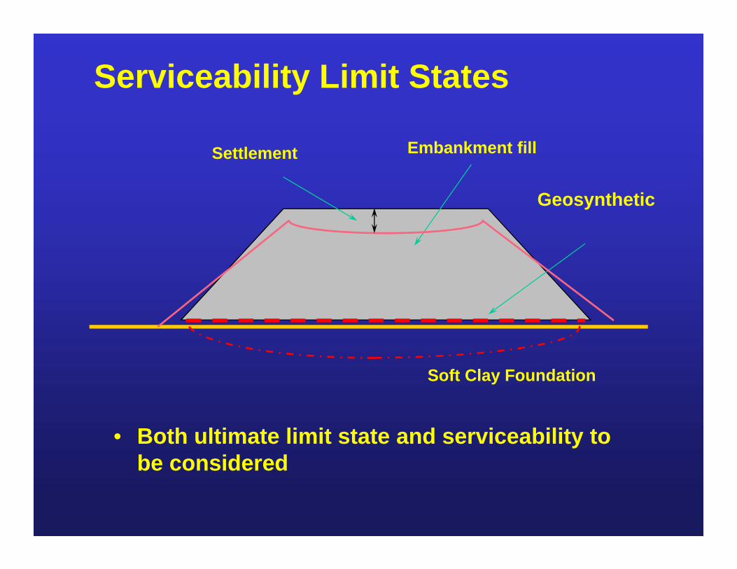
Soft Clay Foundation
Embankment fillSettlement
Serviceability Limit States
• Both ultimate limit state and serviceability to be considered
Geosynthetic
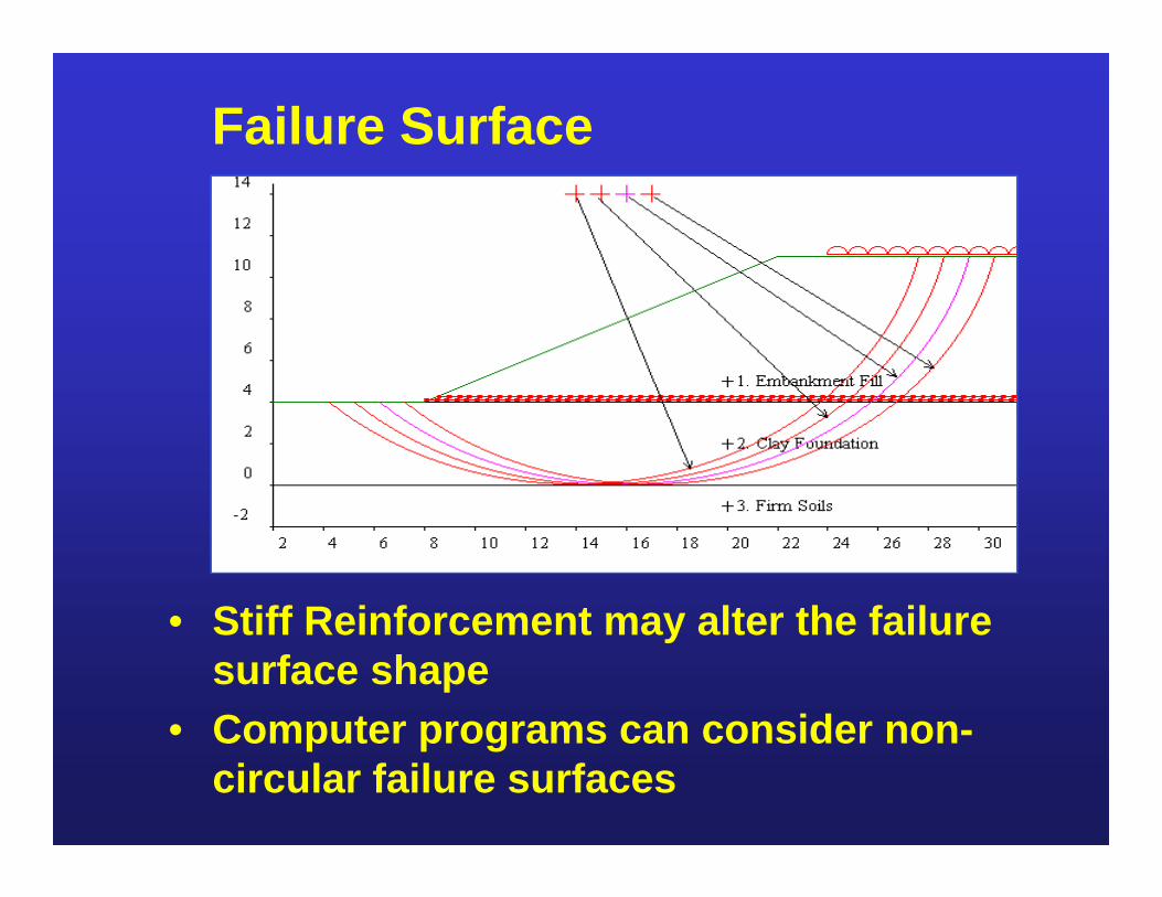
• Stiff Reinforcement may alter the failure surface shape
• Computer programs can consider non-circular failure surfaces
Failure Surface
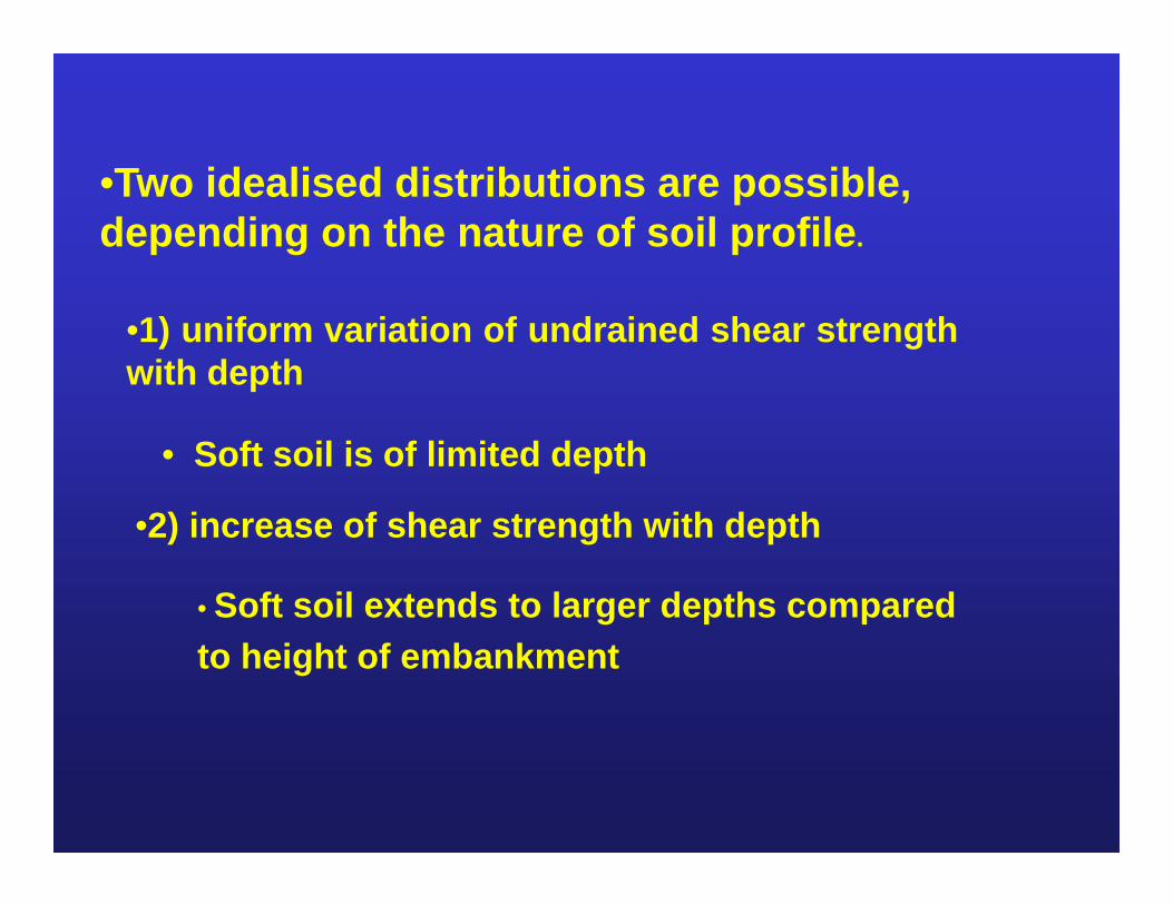
•Two idealised distributions are possible, depending on the nature of soil profile.
•1) uniform variation of undrained shear strengthwith depth
• Soft soil is of limited depth
•2) increase of shear strength with depth
• Soft soil extends to larger depths compared to height of embankment
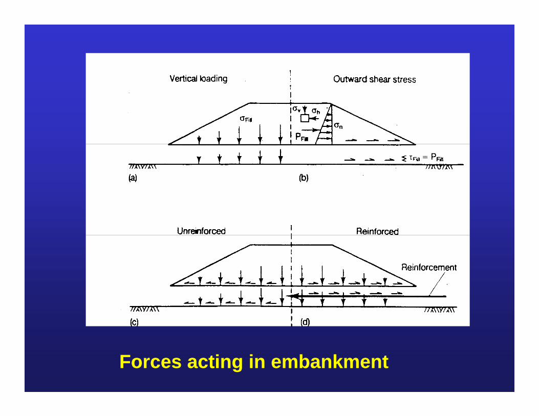
Forces acting in embankment
•Two types of loads need to be considered for equilibrium
•Vertical loading
•Outward directed lateral force Pfill
•To prevent the lateral spreading of the embankment, horizontalstresses within the fill must be balanced by shear reactions at thebase.
•In an unreinforced embankment, the lateral thrust Pfill intransferred to the foundation,
•whereas if reinforcement is present, some of the thrust is carried by the reinforcement itself
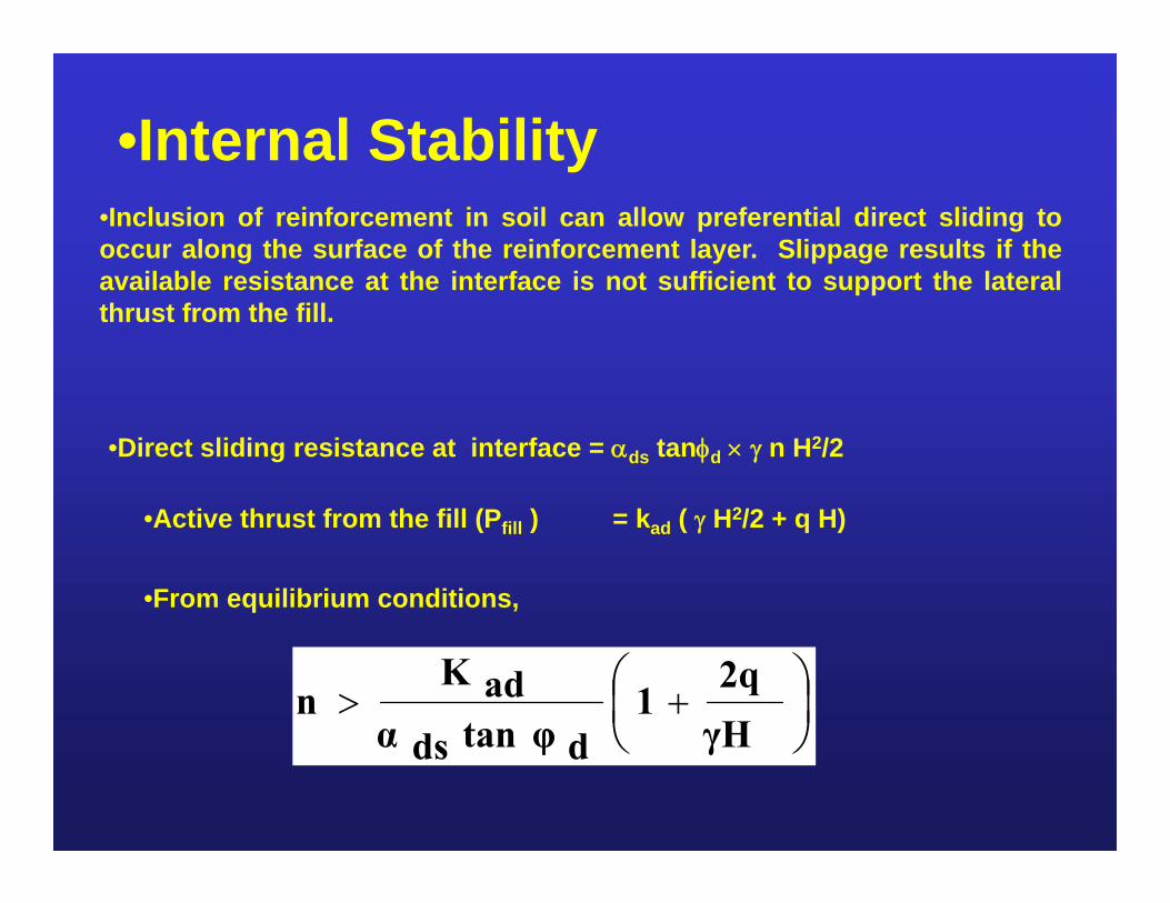
•Internal Stability•Inclusion of reinforcement in soil can allow preferential direct sliding tooccur along the surface of the reinforcement layer. Slippage results if theavailable resistance at the interface is not sufficient to support the lateralthrust from the fill.
•Direct sliding resistance at interface = ds tand n H2/2
•Active thrust from the fill (Pfill ) = kad ( H2/2 + q H)
•From equilibrium conditions,
γH2q
1dtan φdsα
adKn
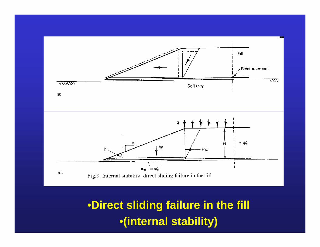
•Direct sliding failure in the fill •(internal stability)
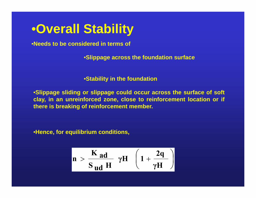
•Overall Stability•Needs to be considered in terms of
•Slippage across the foundation surface
•Stability in the foundation
•Slippage sliding or slippage could occur across the surface of softclay, in an unreinforced zone, close to reinforcement location or ifthere is breaking of reinforcement member.
•Hence, for equilibrium conditions,
γH2q
1γHHudS
adKn
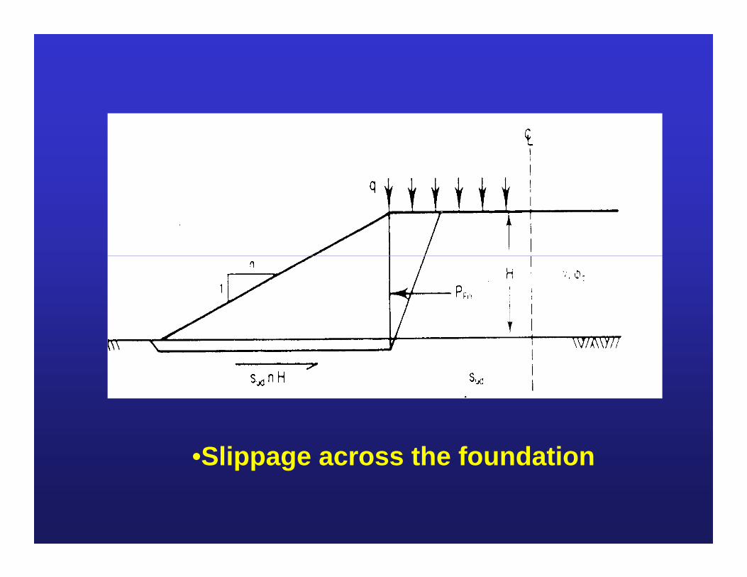
•Slippage across the foundation
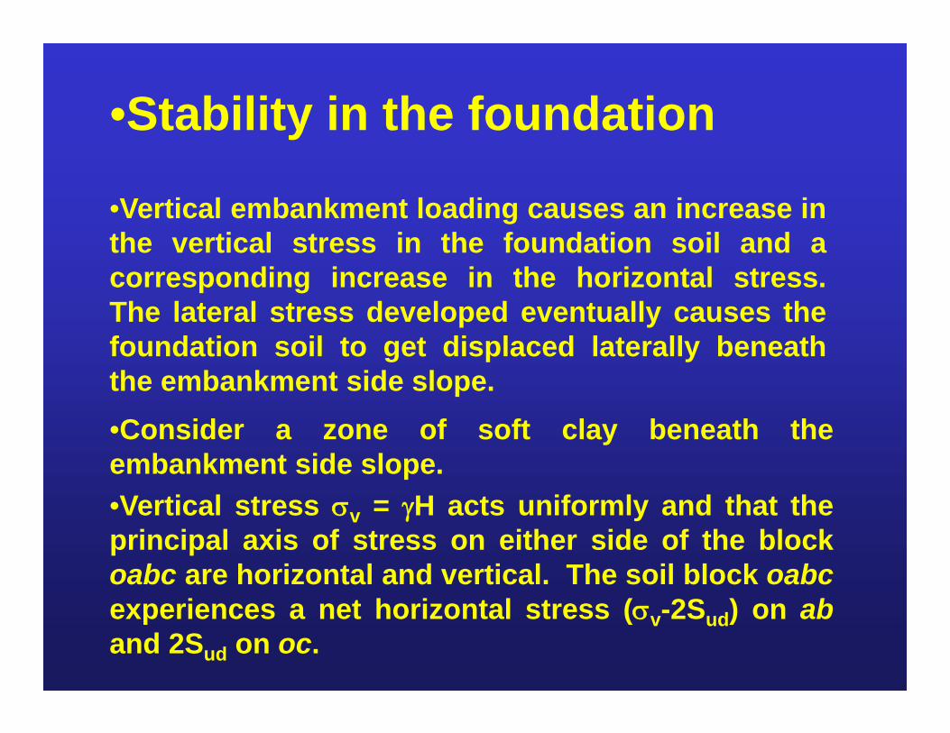
•Stability in the foundation
•Vertical embankment loading causes an increase inthe vertical stress in the foundation soil and acorresponding increase in the horizontal stress.The lateral stress developed eventually causes thefoundation soil to get displaced laterally beneaththe embankment side slope.•Consider a zone of soft clay beneath theembankment side slope.•Vertical stress v = H acts uniformly and that theprincipal axis of stress on either side of the blockoabc are horizontal and vertical. The soil block oabcexperiences a net horizontal stress (v-2Sud) on aband 2Sud on oc.
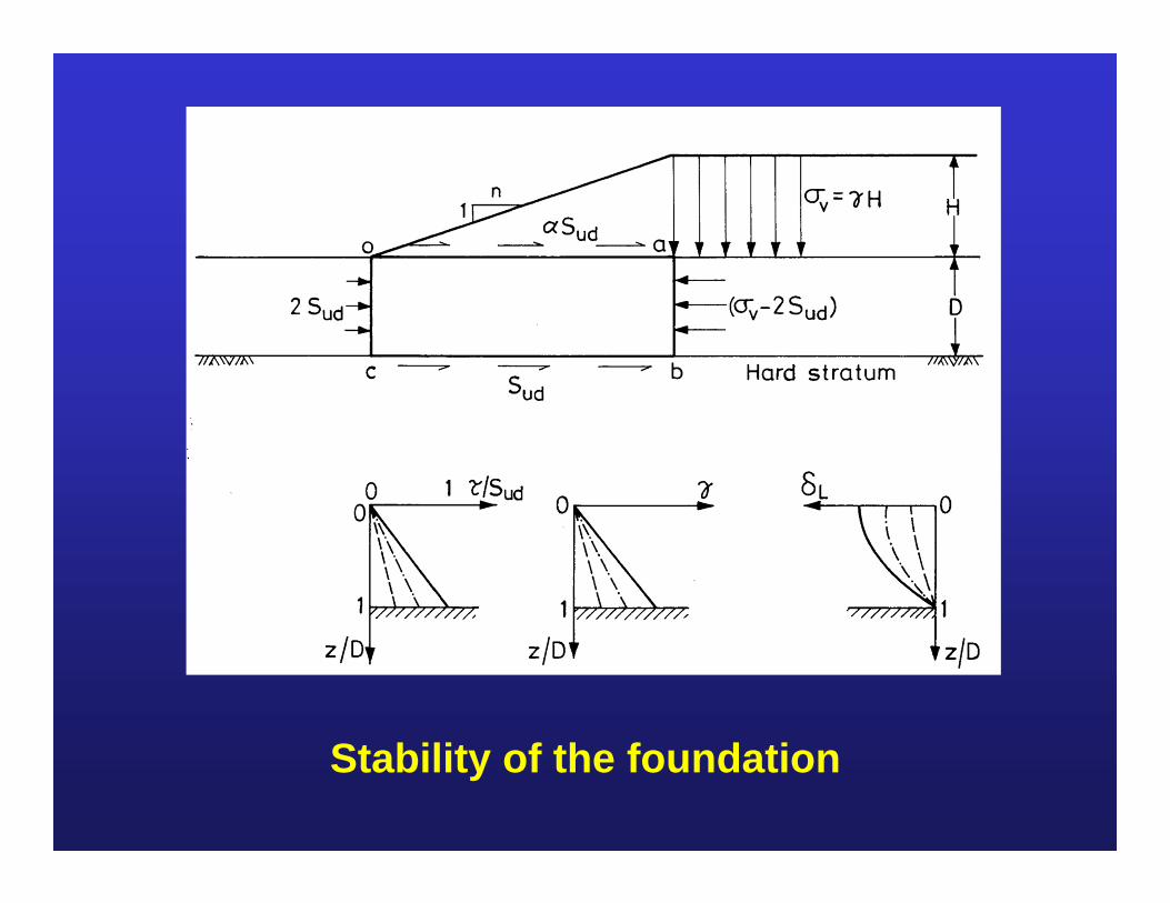
Stability of the foundation
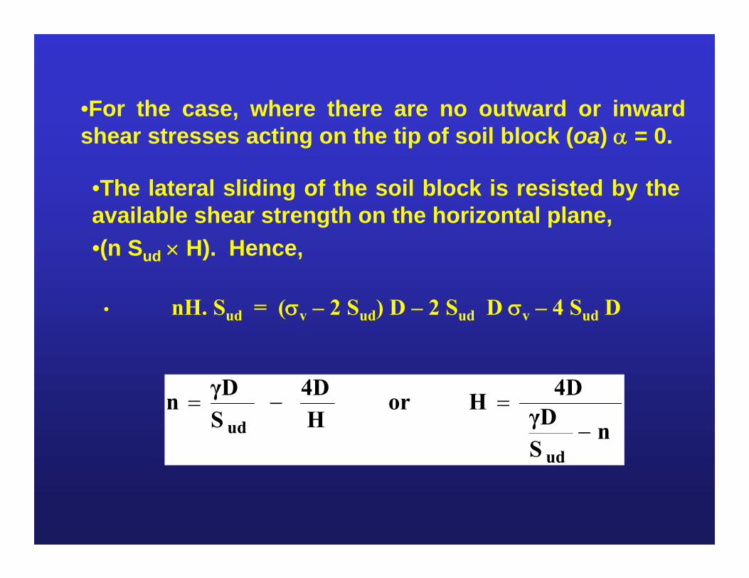
•For the case, where there are no outward or inwardshear stresses acting on the tip of soil block (oa) = 0.
• nH. Sud = (v – 2 Sud) D – 2 Sud D v – 4 Sud D
nSγD4DHor
H4D
SγDn
ud
ud
•The lateral sliding of the soil block is resisted by theavailable shear strength on the horizontal plane,•(n Sud H). Hence,
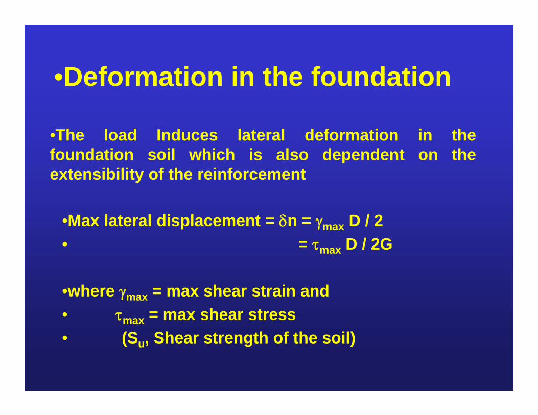
•Deformation in the foundation
•The load Induces lateral deformation in thefoundation soil which is also dependent on theextensibility of the reinforcement
•Max lateral displacement = n = max D / 2• = max D / 2G
•where max = max shear strain and• max = max shear stress• (Su, Shear strength of the soil)
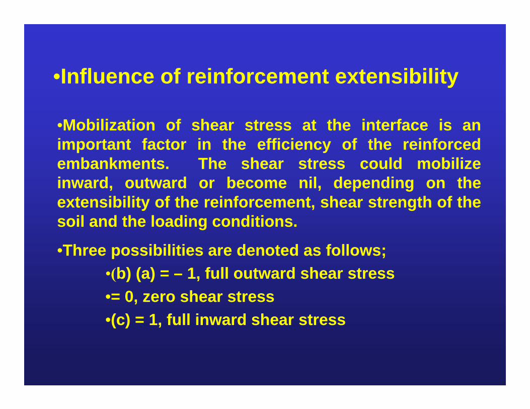
•Influence of reinforcement extensibility
•Mobilization of shear stress at the interface is animportant factor in the efficiency of the reinforcedembankments. The shear stress could mobilizeinward, outward or become nil, depending on theextensibility of the reinforcement, shear strength of thesoil and the loading conditions.
•Three possibilities are denoted as follows;•(b) (a) = – 1, full outward shear stress•= 0, zero shear stress•(c) = 1, full inward shear stress
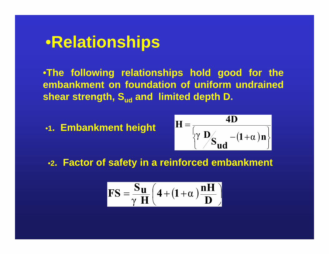
•Relationships•The following relationships hold good for theembankment on foundation of uniform undrainedshear strength, Sud and limited depth D.
•1. Embankment height
n1
udSD
4DHαγ
•2. Factor of safety in a reinforced embankment
D
nH14HuSFS αγ
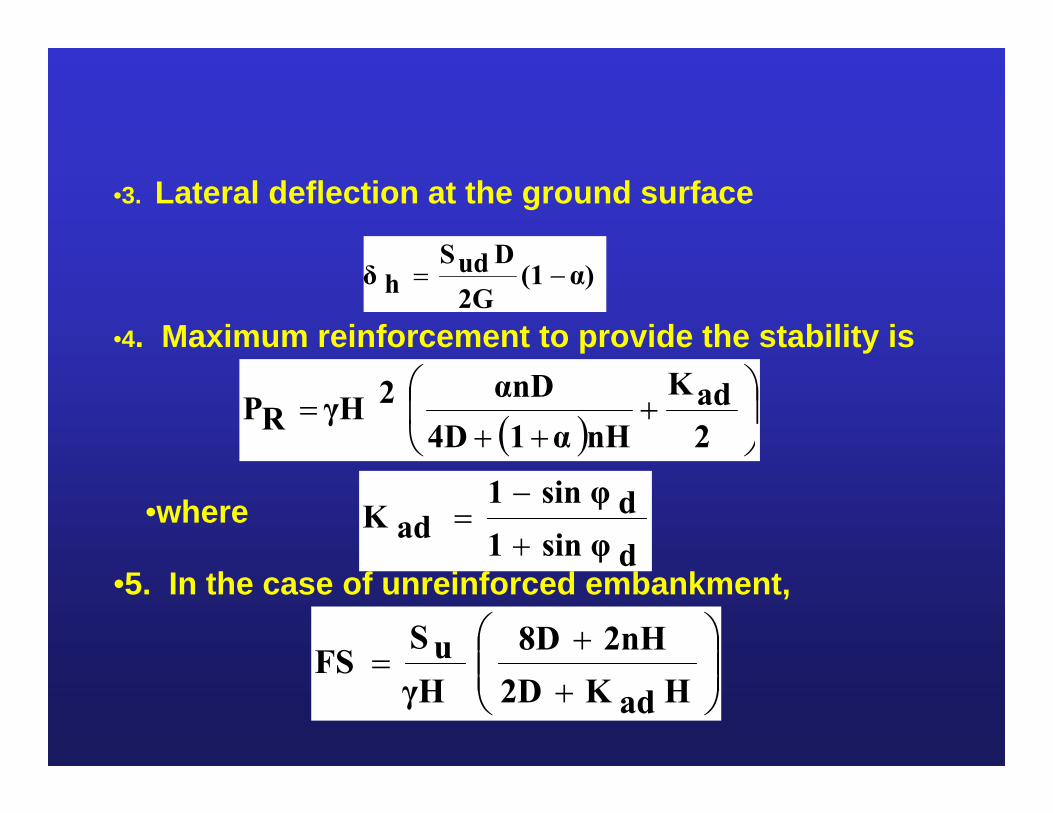
•3. Lateral deflection at the ground surface
α)(12GDudS
hδ
•4. Maximum reinforcement to provide the stability is
2adK
nHα14DαnD2γHRP
•where dsin φ1dsin φ1
adK
•5. In the case of unreinforced embankment,
HadK2D2nH8D
γHuSFS

Example Problem
An embankment of 200m length and 4m height roadembankment with a crest width of 15m needs to beconstructed over soft clay of 4m depth(Su=15kN/m2, constant with depth). The embankmentis constructed rapidly in one stage. End ofconstruction stability needs to be ensured.
Granular fill in the nearly area (d = 20kN/m3) is used(cv = 330). Targeted FS = 1.3
DnH
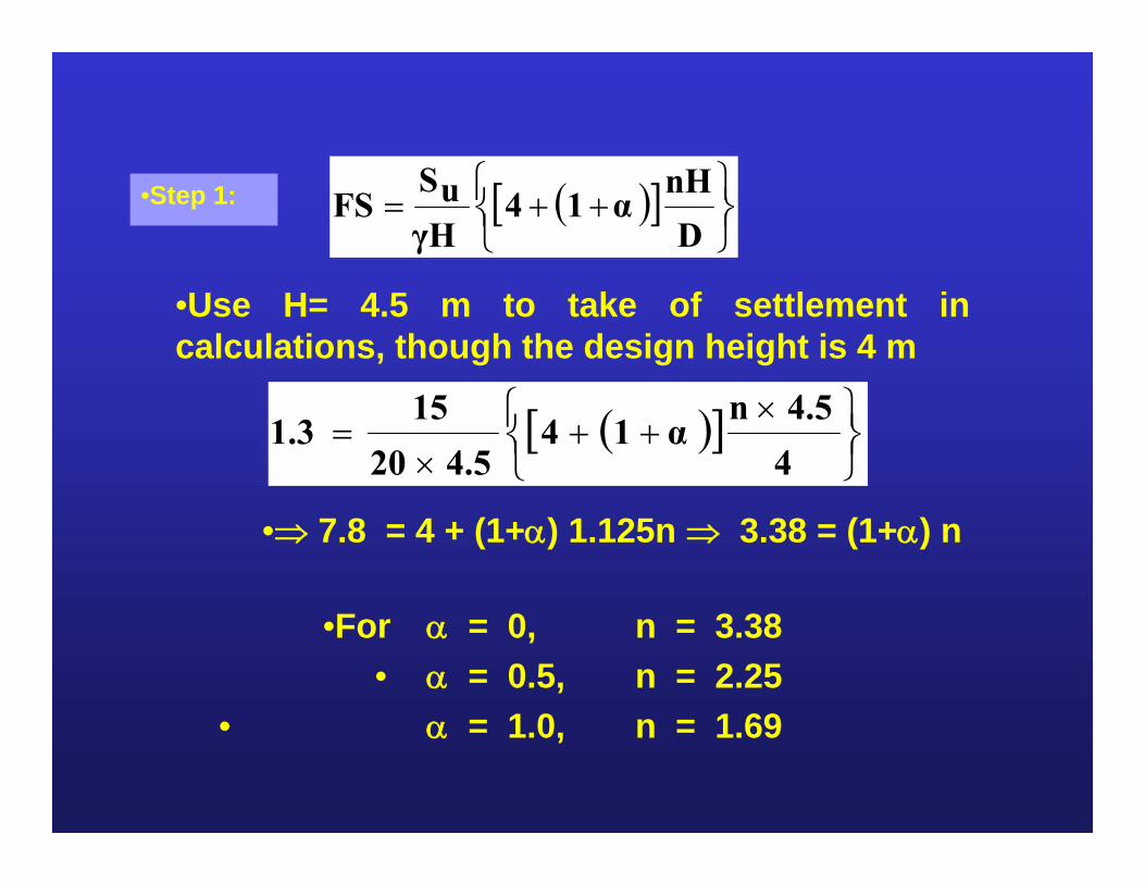
α14γHuSFS•Step 1:
•Use H= 4.5 m to take of settlement incalculations, though the design height is 4 m
44.5n
α144.520
151.3
• 7.8 = 4 + (1+) 1.125n 3.38 = (1+) n
•For = 0, n = 3.38• = 0.5, n = 2.25
• = 1.0, n = 1.69
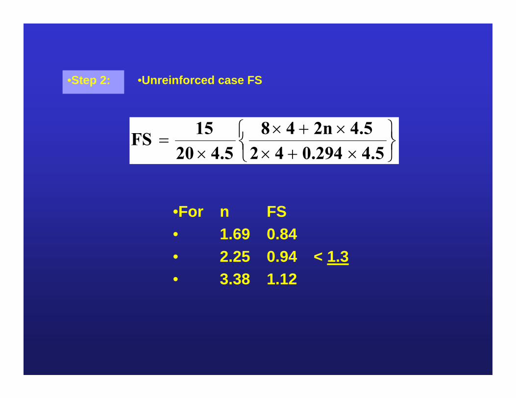
•Unreinforced case FS
4.50.294424.52n48
4.52015FS
•For n FS• 1.69 0.84• 2.25 0.94 < 1.3• 3.38 1.12
•Step 2:
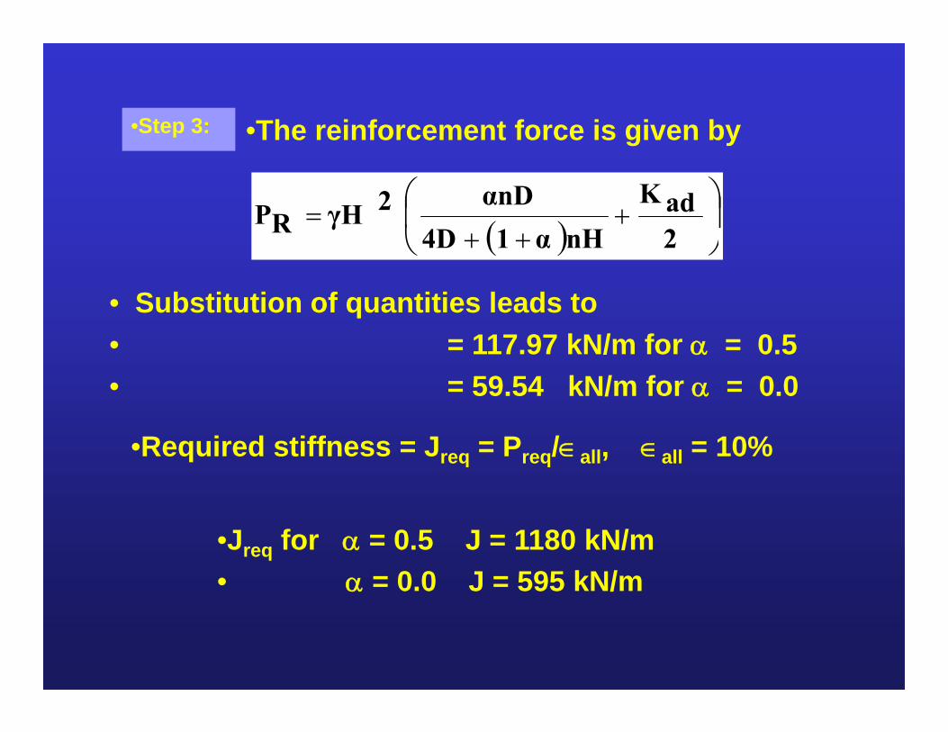
• Substitution of quantities leads to• = 117.97 kN/m for = 0.5• = 59.54 kN/m for = 0.0
•Required stiffness = Jreq = Preq/all, all = 10%
•Jreq for = 0.5 J = 1180 kN/m• = 0.0 J = 595 kN/m
2adK
nHα14DαnD2γHRP
•The reinforcement force is given by•Step 3:
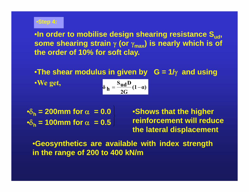
•The shear modulus in given by G = 1/ and using•We get, α)(1
2GDudS
hδ
•Geosynthetics are available with index strengthin the range of 200 to 400 kN/m
•In order to mobilise design shearing resistance Sud,some shearing strain (or max) is nearly which is ofthe order of 10% for soft clay.
•h = 200mm for = 0.0•h = 100mm for = 0.5
•Shows that the higher reinforcement will reduce the lateral displacement
•Step 4:
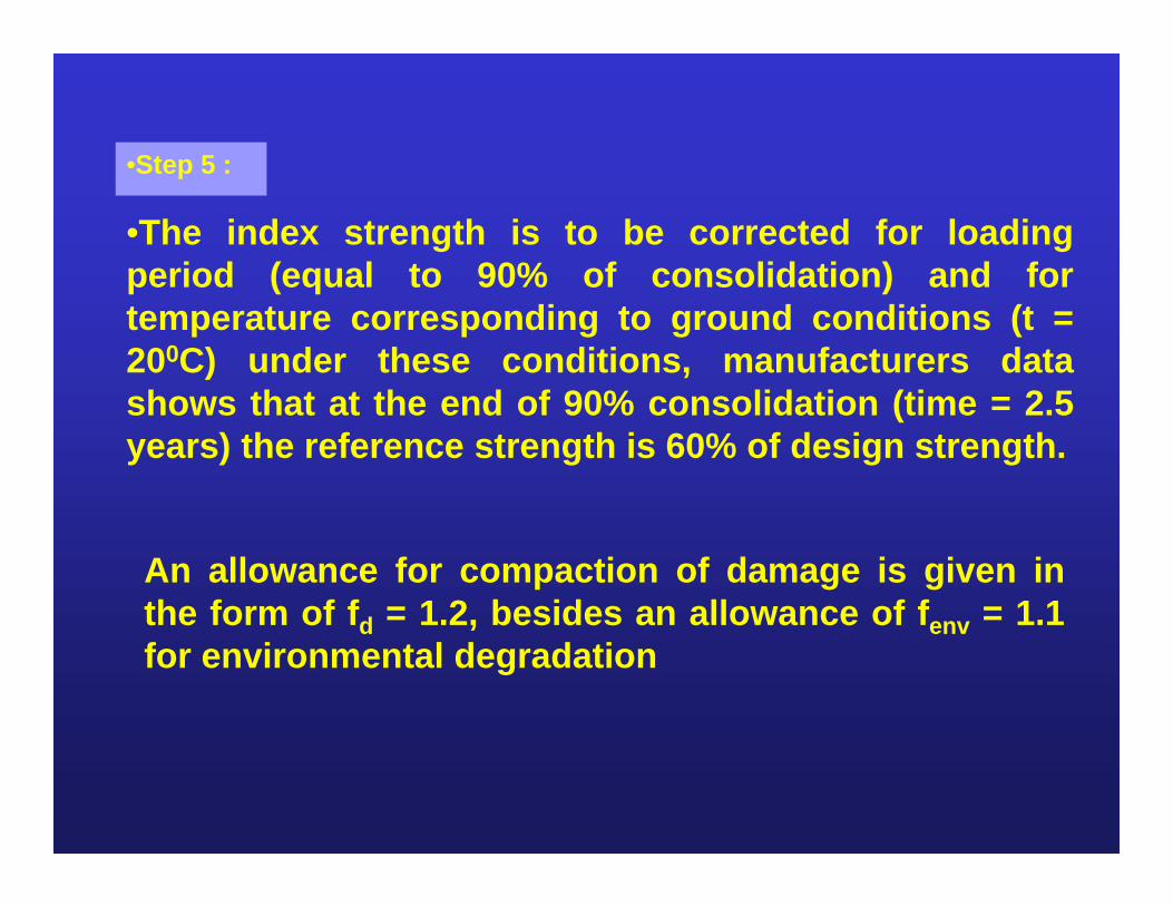
•The index strength is to be corrected for loadingperiod (equal to 90% of consolidation) and fortemperature corresponding to ground conditions (t =200C) under these conditions, manufacturers datashows that at the end of 90% consolidation (time = 2.5years) the reference strength is 60% of design strength.
An allowance for compaction of damage is given inthe form of fd = 1.2, besides an allowance of fenv = 1.1for environmental degradation
•Step 5 :
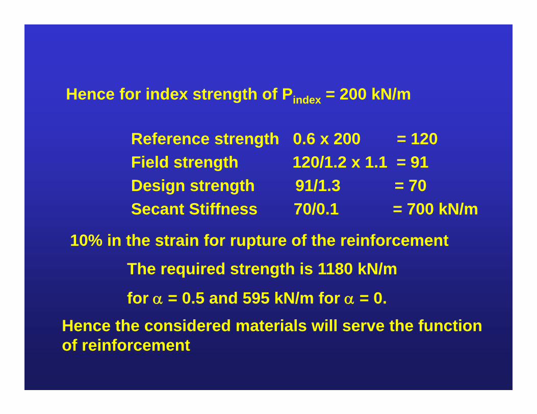
Hence for index strength of Pindex = 200 kN/m
Reference strength 0.6 x 200 = 120Field strength 120/1.2 x 1.1 = 91Design strength 91/1.3 = 70Secant Stiffness 70/0.1 = 700 kN/m
10% in the strain for rupture of the reinforcement
The required strength is 1180 kN/m
for = 0.5 and 595 kN/m for = 0. Hence the considered materials will serve the function of reinforcement
Concluding Remarks
The use of geosynthetics in improving the stability and reduce the settlements in the case of embankments on soft soils, in the construction of loading platforms, preventing the influence of voids in the foundation medium have been beneficial in the ground improvement.

Thank you