Embed Size (px)
Citation preview
Design of Facilities for Physical, Chemical & Biological Treatment of
Waste Water
Design of racks, screens, grit chamber, aeration units, sedimentation tanks, activated sludge and trickling filter processes, rotating biological contactors, sludge digesters and drying beds
Course Content
RACKS & SCREENS...
screen is a device with openings for removing bigger suspended or floating
matter in sewage which would otherwise damage equipment or
interfere with satisfactory operation of treatment units.
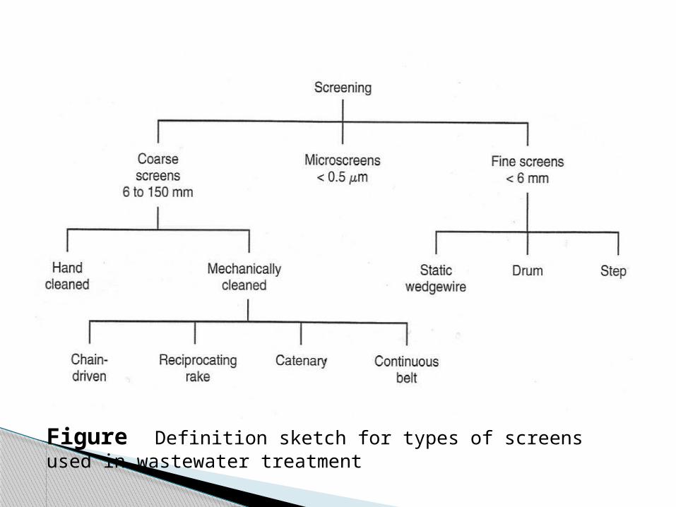
Figure Definition sketch for types of screens used in wastewater treatment
Design ConsiderationVelocity The velocity of flow ahead of and through
the screen varies and affects its operation. The lower the velocity through the screen,
the greater is the amount of screenings that would be removed from sewage.
However, the lower the velocity, the greater would be the amount of solids deposited in the channel.
Hence, the design velocity should be such as to permit 100% removal of material of certain size without undue depositions.
Velocities of 0.6 to 1.2 mps through the open area for the peak flows have been used satisfactorily.
Further, the velocity at low flows in the approach channel should not be less than 0.3 mps to avoid deposition of solids.
Head loss
Head loss varies with the quantity and nature of screenings allowed to accumulate between cleanings.
Head loss through screens mainly depends on:Size and amount of solids in waste waterClear openings between bar Method of cleaning and its frequencyVelocity of flow through the screens
SEDIMENTATION TANKS...
Solid liquid separation process in which a suspension is separated into two phases –
Clarified supernatant leaving the top of the sedimentation tank (overflow).
Concentrated sludge leaving the bottom of the sedimentation tank (underflow).
To remove coarse dispersed phase. To remove coagulated and flocculated
impurities. To remove precipitated impurities after
chemical treatment. To settle the sludge (biomass) after
activated sludge process / tricking filters.
Purpose of Settling
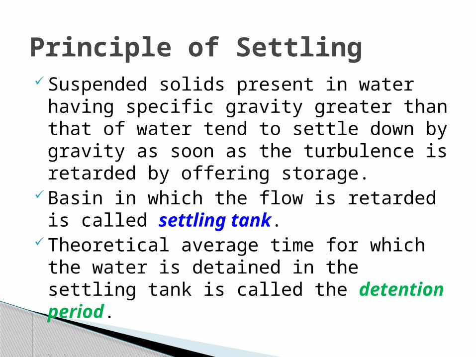
Suspended solids present in water having specific gravity greater than that of water tend to settle down by gravity as soon as the turbulence is retarded by offering storage.
Basin in which the flow is retarded is called settling tank.
Theoretical average time for which the water is detained in the settling tank is called the detention period.
Principle of Settling
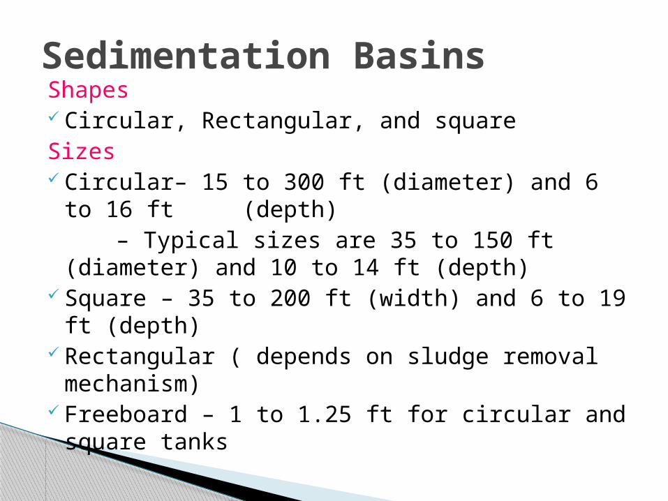
Shapes Circular, Rectangular, and squareSizes Circular– 15 to 300 ft (diameter) and 6 to 16 ft
(depth) – Typical sizes are 35 to 150 ft (diameter) and
10 to 14 ft (depth) Square – 35 to 200 ft (width) and 6 to 19 ft
(depth) Rectangular ( depends on sludge removal
mechanism) Freeboard – 1 to 1.25 ft for circular and square
tanks
Sedimentation Basins
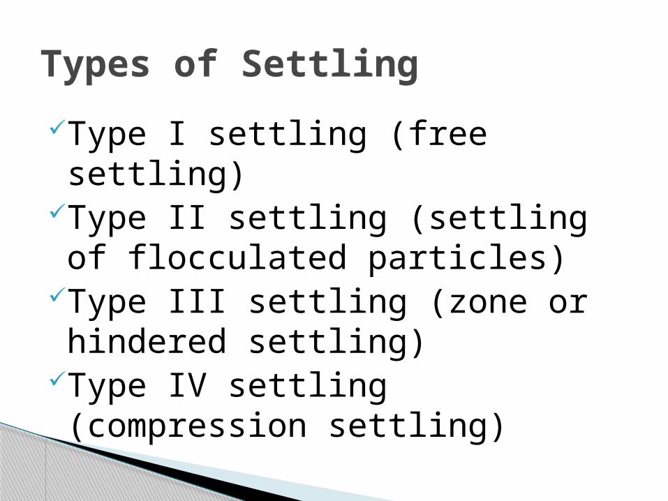
Type I settling (free settling)Type II settling (settling of flocculated particles)
Type III settling (zone or hindered settling)
Type IV settling (compression settling)
Types of Settling
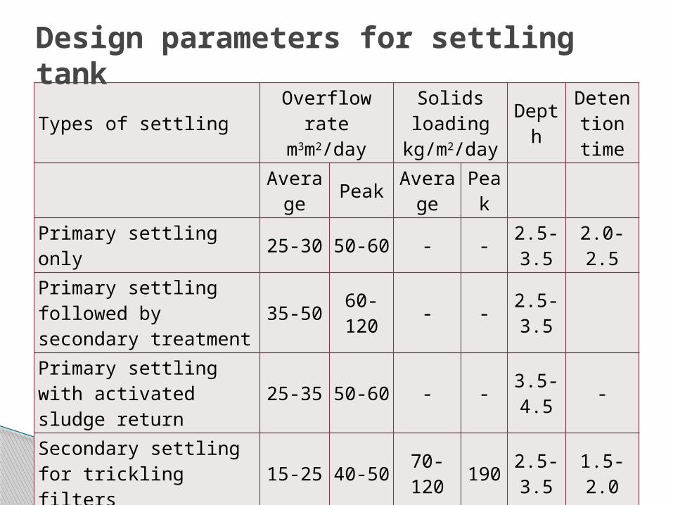
Types of settlingOverflow
rate m3m2/day
Solids loading
kg/m2/day
Depth
Detention
time
Avera
ge PeakAvera
gePeak
Primary settling only 25-30 50-60 - -2.5-3.5 2.0-2.5
Primary settling followed by secondary treatment
35-50 60-120
- - 2.5-3.5
Primary settling with activated sludge return
25-35 50-60 - - 3.5-4.5
-
Secondary settling for trickling filters 15-25 40-50
70-120 190
2.5-3.5 1.5-2.0
Secondary settling for activated sludge (excluding extended aeration)
15-35 40-5070-140 210
3.5-4.5 -
Secondary settling for extended aeration 8-15 25-35
25-120 170
3.5-4.5 -
Design parameters for settling tank
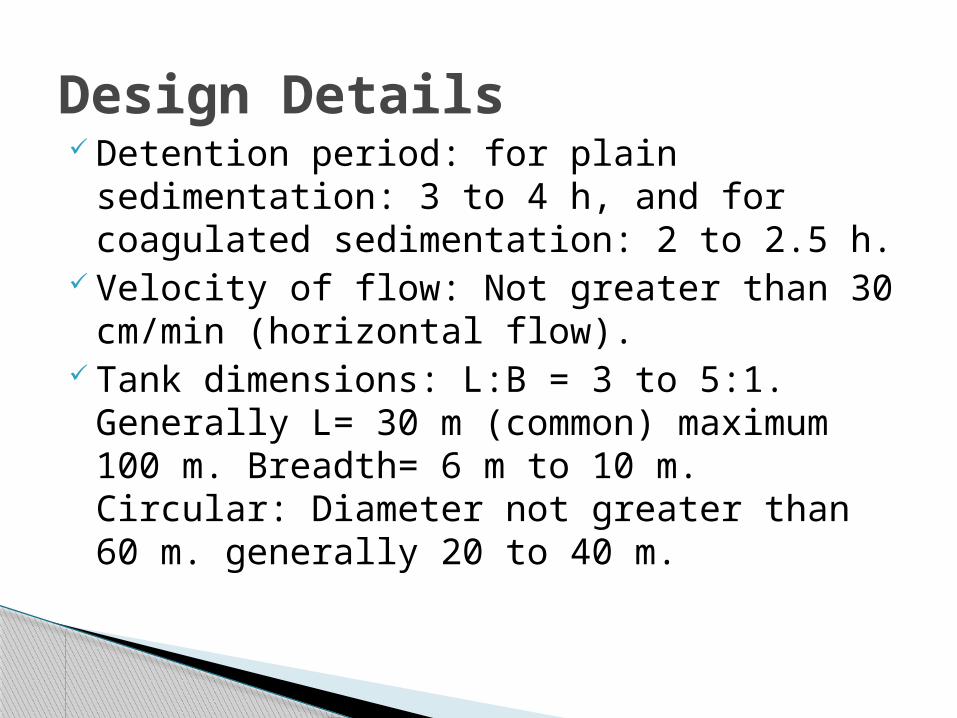
Detention period: for plain sedimentation: 3 to 4 h, and for coagulated sedimentation: 2 to 2.5 h.
Velocity of flow: Not greater than 30 cm/min (horizontal flow).
Tank dimensions: L:B = 3 to 5:1. Generally L= 30 m (common) maximum 100 m. Breadth= 6 m to 10 m. Circular: Diameter not greater than 60 m. generally 20 to 40 m.
Design Details
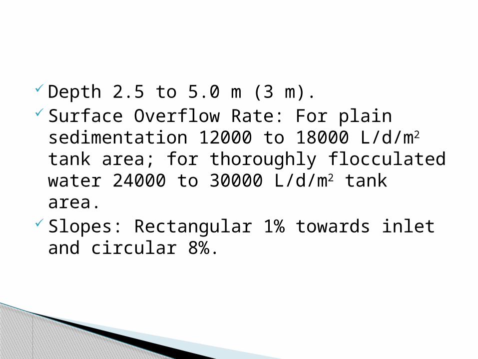
Depth 2.5 to 5.0 m (3 m). Surface Overflow Rate: For plain
sedimentation 12000 to 18000 L/d/m2 tank area; for thoroughly flocculated water 24000 to 30000 L/d/m2 tank area.
Slopes: Rectangular 1% towards inlet and circular 8%.
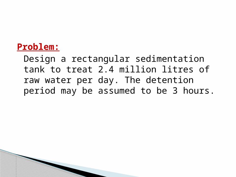
Problem: Design a rectangular sedimentation tank to treat 2.4 million litres of raw water per day. The detention period may be assumed to be 3 hours.
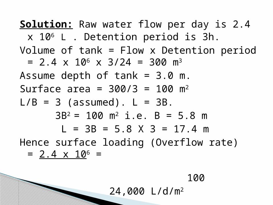
Solution: Raw water flow per day is 2.4 x 10⁶ L . Detention period is 3h.
Volume of tank = Flow x Detention period = 2.4 x 106 x 3/24 = 300 m3
Assume depth of tank = 3.0 m.Surface area = 300/3 = 100 m2
L/B = 3 (assumed). L = 3B. 3B2 = 100 m2 i.e. B = 5.8 m L = 3B = 5.8 X 3 = 17.4 mHence surface loading (Overflow rate) = 2.4 x
106 = 100
24,000 L/d/m2
GRIT CHAMBER...
Grit chambers are basin to remove the inorganic particles to prevent damage to the pumps,
and to prevent their accumulation in sludge
digesters.
Mechanically cleaned Manually cleaned In mechanically cleaned grit chamber,
scraper blades collect the grit settled on the floor of the grit chamber.
The grit so collected is elevated to the ground level by several mechanisms such as bucket elevators, jet pump and air lift.
Manually cleaned grit chambers should be cleaned at least once a week.
The simplest method of cleaning is by means of shovel.
Types of Grit Chambers
An aerated grit chamber consists of a standard spiral flow aeration tank provided with air diffusion tubes placed on one side of the tank.
The grit particles tend to settle down to the bottom of the tank.
Settling rates dependant upon the particle size and the bottom velocity of roll of the spiral flow.
Aerated Grit Chamber

Recommended for horizontal flow and aerated grit chamber.
Flow= maximum Detention time= 30-90 s (usually 60 s) Flow through velocity, vh= 0.2-0.4 m/s
(usually 0.3 m/s) Settling velocity= 0.016-0.021 m/s for 0.2
mm dia particle = 0.01-0.015 m/s for 0.15
mm dia particles Liquid depth= 1-1.5 m Length= 3-25 m Quantity of grits= 0.022-0.075 m3/1000 m3 of
flow
Design criteria
AERATION UNITS...
Unit process in which air and water are brought into intimate contact.
The contact time and ratio of air to water must be sufficient for exchange sufficient oxygen.
AdvantagesProviding O2 for purification and improving
overall quality.CO2 reduction-reduces the corrosion.Raising the pH.VOC removalEffective method for bacterial control
Diffused aeration
Spray aeration
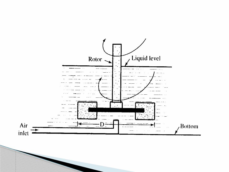
Turbine aeration
Surface aeration
Methods of aeration
Providing maximum water surface per unit volume of air.
Air bubbles brought with water in a mixing or contact chamber.
A common way to aerate water is via diffused air.
Air is pumped through some sort of diffuser to generate small bubbles.
Diffused aeration
Usually gas is injected into the bottom of the aeration tank and is allowed to rise to the surface in an open tank.
The rising bubbles transfer oxygen to the water, as well as transport bottom water to the surface.
The bubbles raising through water create turbulence.
Untreated water is allowed to enter the tank from top and exit from bottom.
Efficiency of diffused aeration can be improved:
Fine bubbles (0.2 cm dia) as compared to coarse bubble (2.5 cm dia)
By increasing water depth (9-15 ft) By improving the basin geometry (width to
depth ratio not exceed 2) By increasing the retention time (10-30 min)
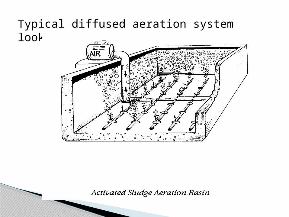
Typical diffused aeration system looks like:
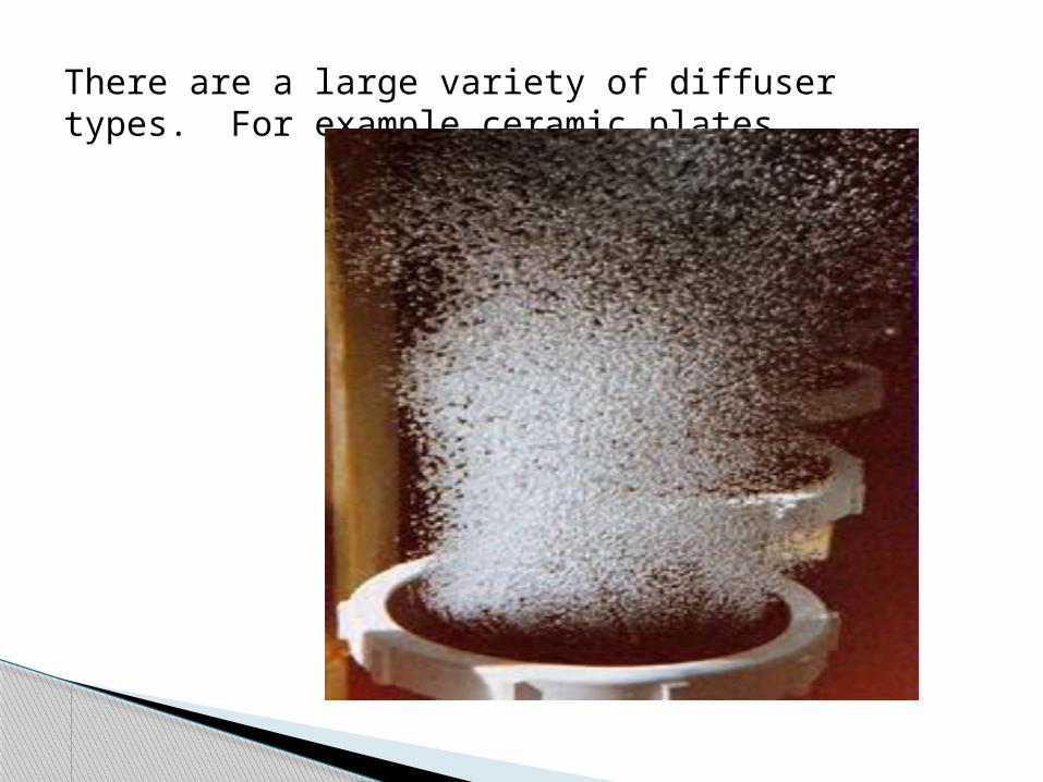
There are a large variety of diffuser types. For example ceramic plates
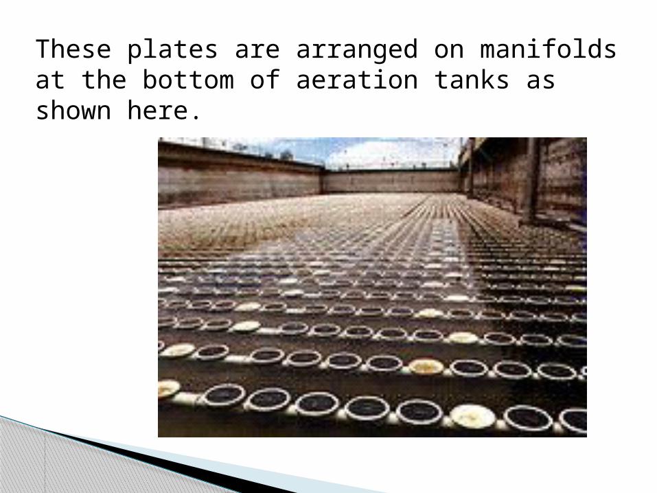
These plates are arranged on manifolds at the bottom of aeration tanks as shown here.
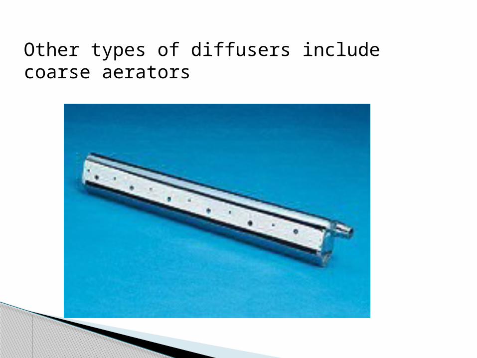
Other types of diffusers include coarse aerators
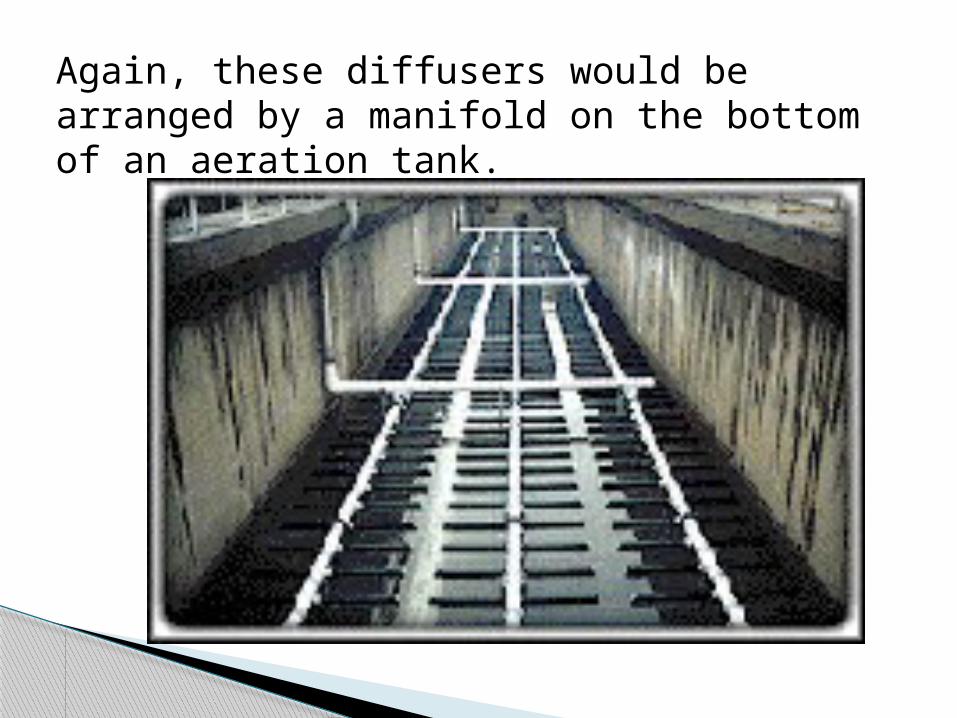
Again, these diffusers would be arranged by a manifold on the bottom of an aeration tank.
Basically there are two types of mechanical aeration.
Turbine Aeration: In this system coarse bubbles are injected
into the bottom of the tank and then a
turbine shears the bubbles for better
oxygen transfer. Efficiency of turbine aerators is generally
higher than diffused aeration.
Mechanical Aeration
Surface Aeration:
In this case a mixing device is used to disturb the surface so that there is increased interfacial area between liquid and air.
There are many different proprietary types of surface aerators .
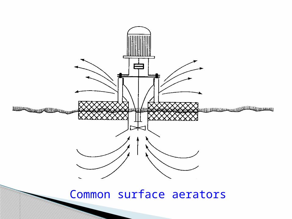
Common surface aerators
ACTIVATED SLUDGE PROCESSES…
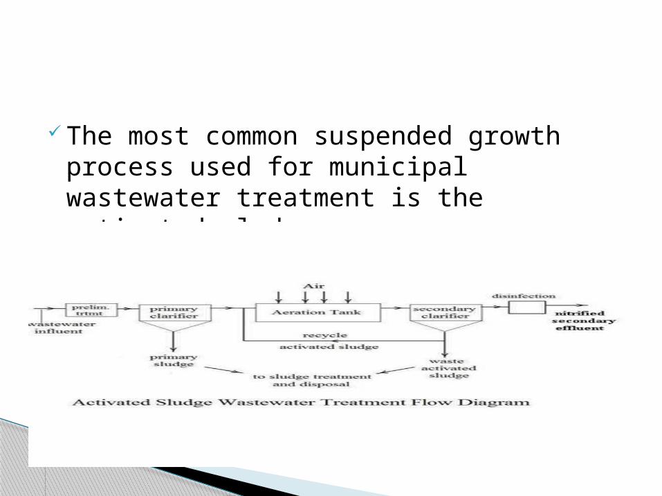
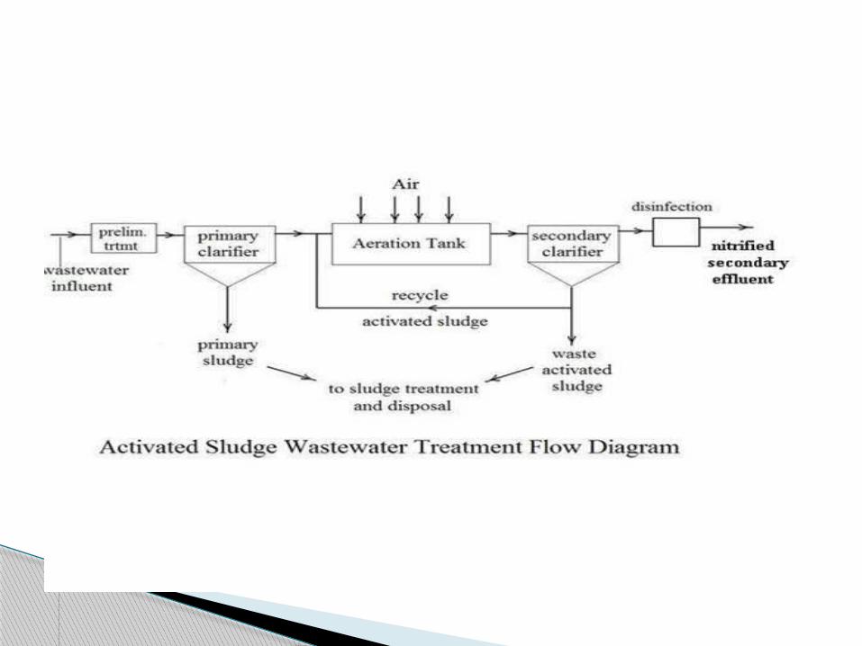
The most common suspended growth process used for municipal wastewater treatment is the activated sludge process.
Activated sludge plant involves:
1.wastewater aeration in the presence of a microbial suspension,
2.solid-liquid separation following aeration, 3.discharge of clarified effluent, 4.wasting of excess biomass, and 5.return of remaining biomass to the aeration tank.
The process involves air or oxygen being introduced into a mixture of primary treated or screened sewage or industrial wastewater combined with organisms to develop a biological floc which reduces the organic content of the sewage.
The combination of wastewater and biological mass is commonly known as mixed liquor.
In all activated sludge plants, once the wastewater has received sufficient treatment, excess mixed liquor is discharged into settling tanks and the treated supernatant is run off to undergo further treatment before discharge.
Process
Part of the settled material, the sludge, is returned to the head of the aeration system to re-seed the new wastewater entering the tank.
This fraction of the floc is called return activated sludge (R.A.S.). Excess sludge is called surplus activated sludge(S.A.S.) or waste activated sludge(W.A.S).
S.A.S is removed from the treatment process to keep the ratio of biomass to food supplied in the wastewater in balance.
S.A.S is stored in sludge tanks and is further treated by digestion, either under anaerobic or aerobic conditions prior to disposal.
Diverse; can be used for one household up a huge plant
Removes organics Oxidation and Nitrification achieved Biological nitrification without adding
chemicals Biological Phosphorus removal Solids/ Liquids separation Stabilization of sludge Capable of removing ~ 97% of suspended
solids The most widely used wastewater treatment
process
Advantages
Does not remove color from industrial wastes and may increase the color through formation of highly colored intermediates through oxidation
Does not remove nutrients, tertiary treatment is necessary
Problem of getting well settled sludge
Recycle biomass keeps high biomass concentration in aeration tanks
Disadvantages
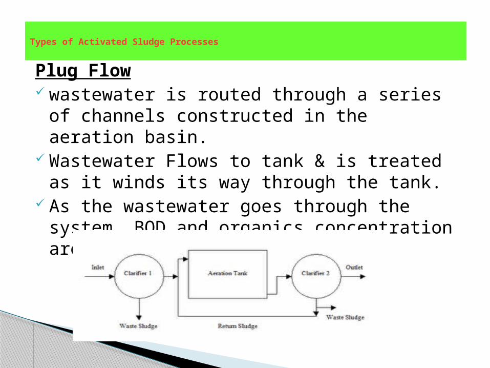
Plug Flow wastewater is routed through a series of
channels constructed in the aeration basin. Wastewater Flows to tank & is treated as it
winds its way through the tank. As the wastewater goes through the system,
BOD and organics concentration are greatly reduced.
Types of Activated Sludge Processes
Variations to this method include:
adding return sludge and/or in decreasing amounts at various locations along length of the tank;
wastewater BOD is reduced as it passes through tank,
air requirements and number of bacteria required also decrease accordingly.
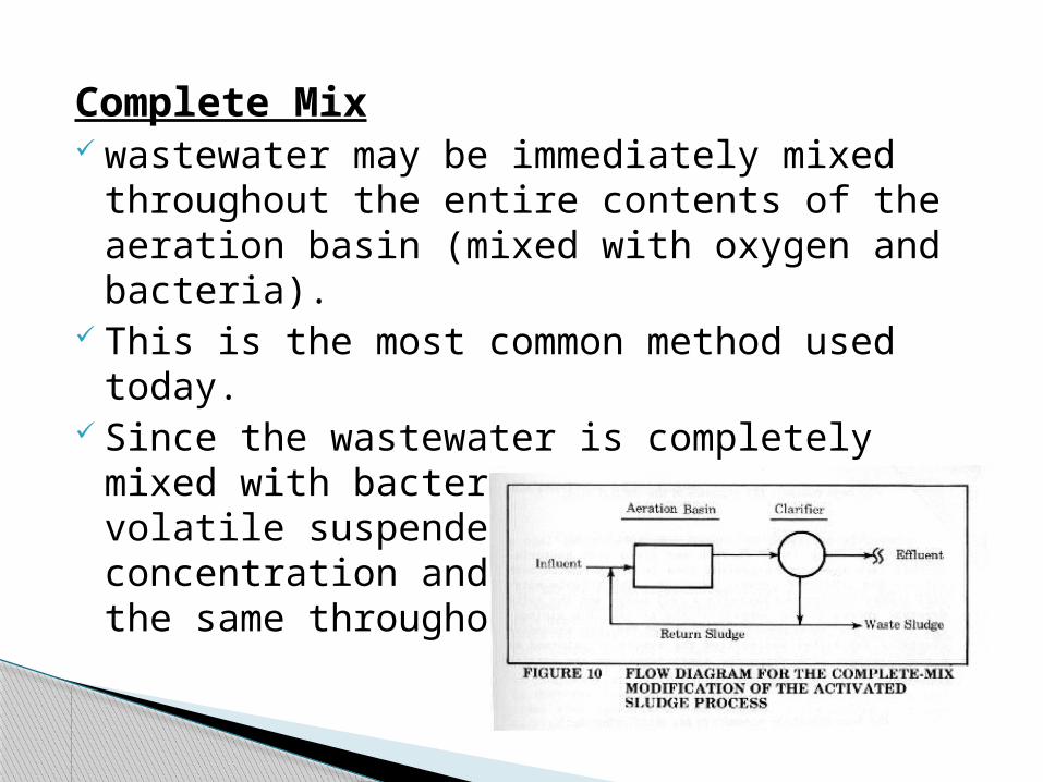
Complete Mix wastewater may be immediately mixed
throughout the entire contents of the aeration basin (mixed with oxygen and bacteria).
This is the most common method used today. Since the wastewater is completely mixed
with bacteria and oxygen, the volatile suspended solids concentration and oxygen demand are the same throughout the tank.
Contact Stabilization Microorganisms consume organics in the
contact tank. Raw wastewater flows into the contact tank
where it is aerated and mixed with bacteria. Soluble materials pass through bacterial cell
walls, while insoluble materials stick to the outside.
Solids settle out later and are wasted from the system or returned to a stabilization tank.
Microbes digest organics in the stabilization tank, and are then recycled back to the contact tank, because they need more food.
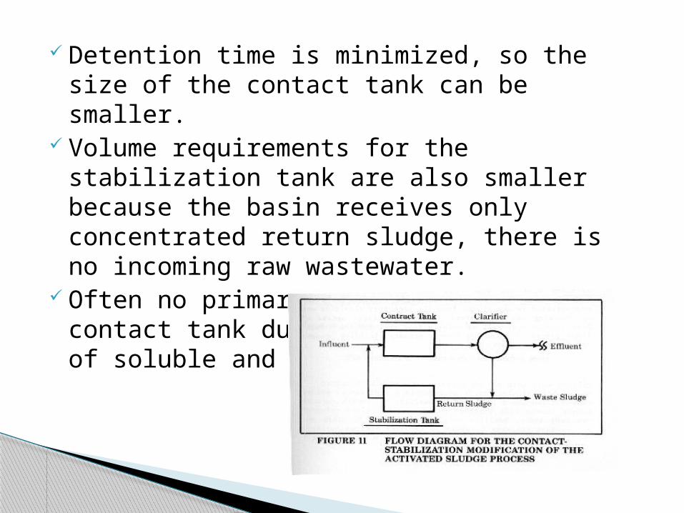
Detention time is minimized, so the size of the contact tank can be smaller.
Volume requirements for the stabilization tank are also smaller because the basin receives only concentrated return sludge, there is no incoming raw wastewater.
Often no primary clarifier before the contact tank due to the rapid uptake of soluble and insoluble food.
Extended Aeration
Used to treat industrial wastewater containing soluble organics that need longer detention times.
This is the same as complete mix, with just a longer aeration.
Advantage - long detention time in the aeration tank; provides equalization to absorb sudden/temporary shock loads.
Less sludge is generally produced because some of the bacteria are digested in the aeration tank.
One of the simpler modifications to operate.
The quality or characteristics of raw waste water to be treated.
The desired quality or characteristics of effluent or treated waste water.
The type of reactor that will be used.
Volumetric and organic loading that will be applied to the reactor.
Design Consideration
Amount of O2 required and the aeration system will provide to supply O2 and to support mixing.
The quantity of sludge that will be generated and wasted for its further management.
Besides these nutrient requirements of microbes, environmental conditions under which plant operated.
The design computations require the determination of:
Volume or dimensions of the aeration tankAmount of O2 required and power needed for
aerationQuantity of sludge that will produced for
particular waste and treatment conditions Volume and dimensions of sec. settling tank
Design steps
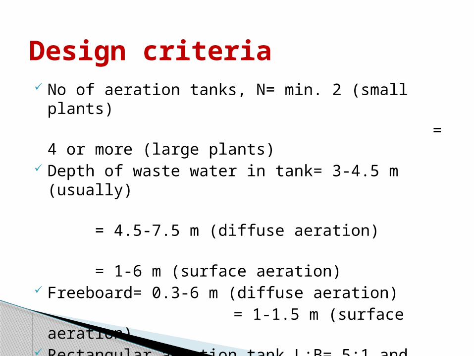
No of aeration tanks, N= min. 2 (small plants) = 4 or more (large
plants) Depth of waste water in tank= 3-4.5 m (usually) = 4.5-7.5 m (diffuse
aeration) = 1-6 m (surface
aeration) Freeboard= 0.3-6 m (diffuse aeration) = 1-1.5 m (surface aeration) Rectangular aeration tank L:B= 5:1 and B:D=3:1
to 4:1 (depends on the aeration system)
Design criteria
Air requirement:I. 20-55 m3 of air/Kg of BOD removed for
diffuse aeration when F/M => 0.3II. 70-115 m3 air/Kg of BOD removed for
diffuse aeration when F/M <= 0.3 Power required for complete mixing : 10-
14 kW/1000 m3 of tank volume for surface aeration system
TRICKLING FILTER PROCESSES…
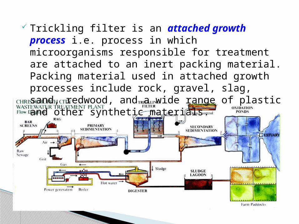
Trickling filter is an attached growth process i.e. process in which microorganisms responsible for treatment are attached to an inert packing material. Packing material used in attached growth processes include rock, gravel, slag, sand, redwood, and a wide range of plastic and other synthetic materials.
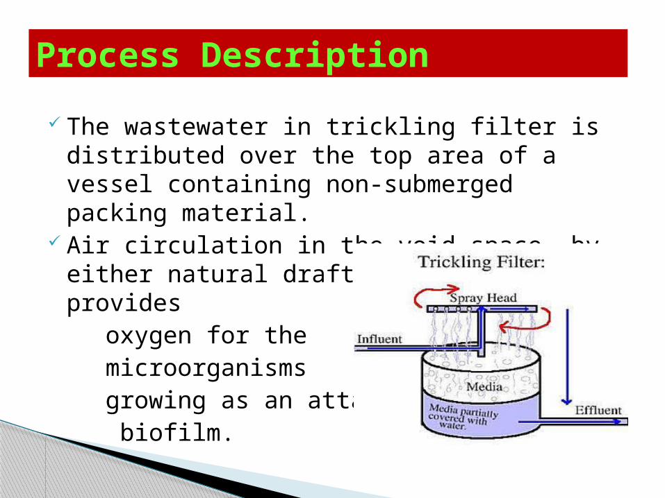
The wastewater in trickling filter is distributed over the top area of a vessel containing non-submerged packing material.
Air circulation in the void space, by either natural draft or blowers, provides
oxygen for the microorganisms growing as an attached biofilm.
Process Description
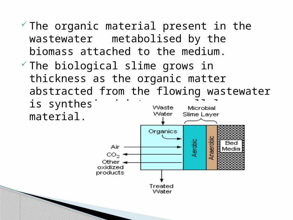
The organic material present in the wastewater metabolised by the biomass attached to the medium.
The biological slime grows in thickness as the organic matter abstracted from the flowing wastewater is synthesized into new cellular material.
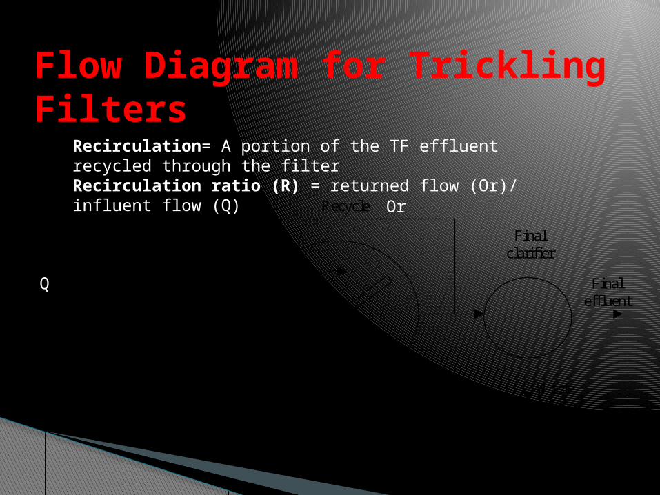
Flow Diagram for Trickling Filters
Recycle
Primaryclarifier Trickling
filter
Finalclarifier
Wastesludge
FinaleffluentInfluent
Q
Or
Recirculation= A portion of the TF effluent recycled through the filterRecirculation ratio (R) = returned flow (Or)/ influent flow (Q)
simplicity of operation
resistance to shock loads
low sludge yield
low power requirements
Advantages
relatively low BOD removal (85%)
high suspended solids in the effluent (20 -30 mg/L)
little operational control
Disadvantages
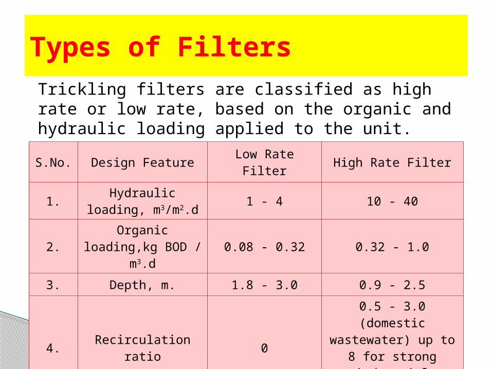
S.No. Design Feature Low Rate Filter High Rate Filter
1. Hydraulic loading, m3/m2.d 1 - 4 10 - 40
2. Organic loading,kg BOD / m3.d 0.08 - 0.32 0.32 - 1.0
3. Depth, m. 1.8 - 3.0 0.9 - 2.5
4. Recirculation ratio 0
0.5 - 3.0 (domestic wastewater) up to 8 for strong industrial
wastewater.
Types of FiltersTrickling filters are classified as high rate or low rate, based on the organic and hydraulic loading applied to the unit.
Hydraulic loading rate is the total flow including recirculation applied on unit area of the filter in a day.
Organic loading rate is the 5 day 20°C BOD, excluding the BOD of the recirculant, applied per unit volume in a day.
Recirculation is generally not adopted in low rate filters.
A well operated low rate trickling filter in combination with secondary settling tank may remove 75 to 90% BOD and suitable for treatment of low to medium strength domestic wastewaters.
The high rate trickling filter, single stage or two stage are recommended for medium to relatively high strength domestic and industrial wastewater.
The BOD removal efficiency is around 75 to 90%.
Single stage unit consists of a primary settling tank, filter, secondary settling tank and facilities for recirculation of the effluent.
Two stage filters consist of two filters in series with a primary settling tank, an intermediate settling tank which may be omitted in certain cases and a final settling tank.
Generally trickling filter design is based on empirical relationships to find the required filter volume for a designed degree of wastewater treatment.
NRC equations commonly used. NRC (National Research Council of USA)
equations give satisfactory values when there is no re-circulation, the seasonal variations in temperature are not large and fluctuations with high organic loading.
Process Design
ROTATING BIOLOGICAL CONTRACTORS (RBC)…
Rotating Biological Contactors, commonly called RBC’s, are used in wastewater
treatment plants (WWTPs). The primary function of these bio-reactors at WWTPs is
the reduction of organic matter.
A fixed growth biological treatment processes used to consume organic matter (BOD) from wastewater.
Consists of 2-6 m diameter disks, closely spaced on a rotating horizontal axis.
Disks are covered with a biofilm. The disks are only partially submerged in
wastewater.
As the disk rotates the biofilm is exposed to the wastewater only part of the time.
The rotation in and out of the wastewater serves to vary the feeding cycle of the bacteria and microorganisms that make up the biofilm.
The shaft rotates about 1-10 rpm (slowly).
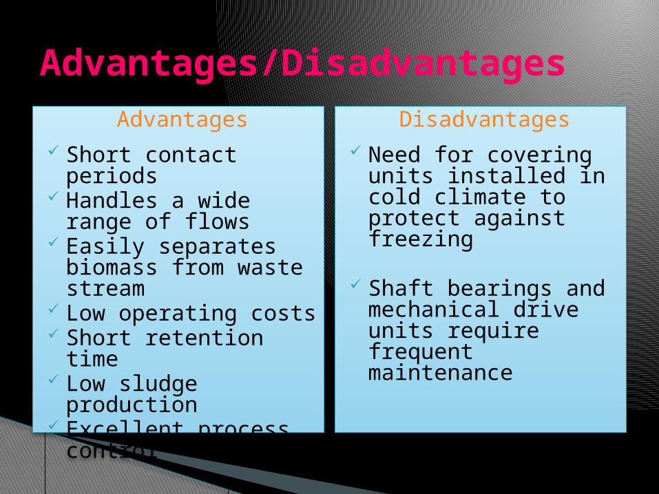
Advantages Short contact periods Handles a wide range
of flows Easily separates
biomass from waste stream
Low operating costs Short retention time Low sludge production Excellent process
control
Disadvantages Need for covering
units installed in cold climate to protect against freezing
Shaft bearings and mechanical drive units require frequent maintenance
Advantages/Disadvantages
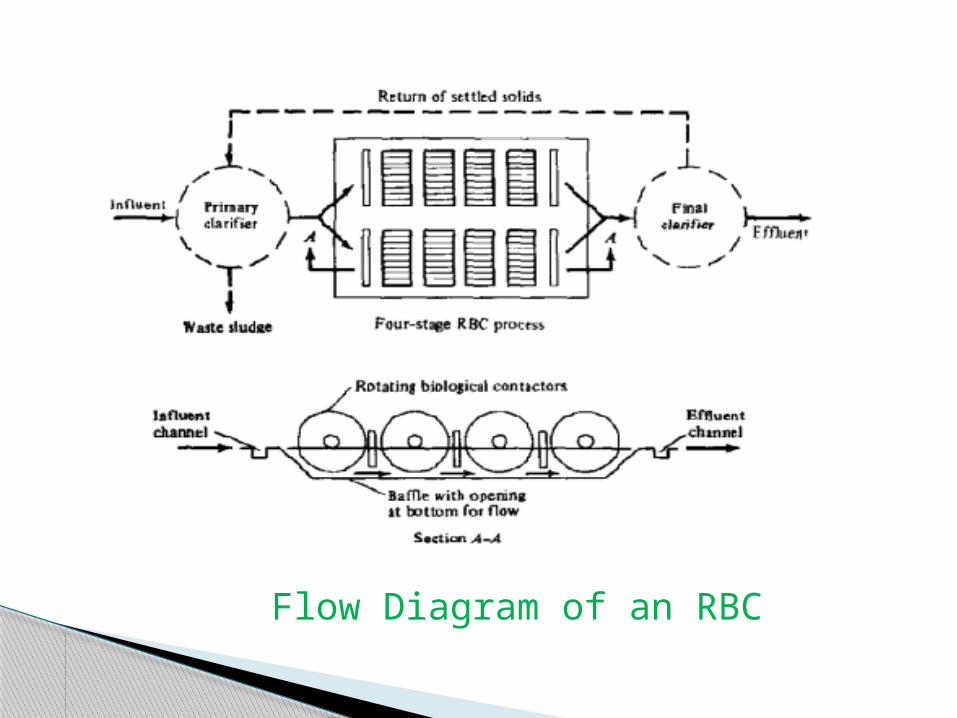
Flow Diagram of an RBC
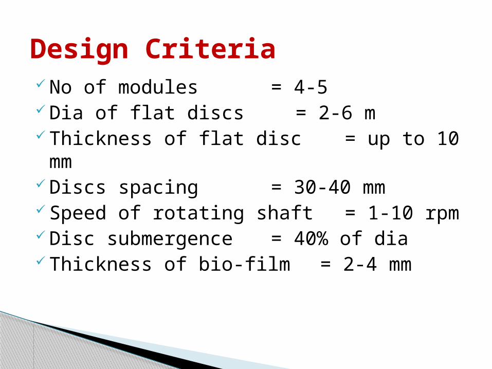
No of modules = 4-5 Dia of flat discs = 2-6 m Thickness of flat disc = up to 10
mm Discs spacing = 30-40 mm Speed of rotating shaft = 1-10 rpm Disc submergence = 40% of dia Thickness of bio-film = 2-4 mm
Design Criteria
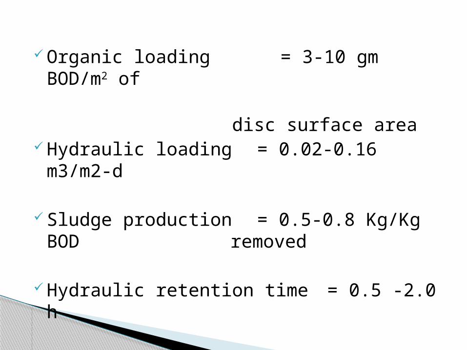
Organic loading = 3-10 gm BOD/m2 of
disc surface area
Hydraulic loading = 0.02-0.16 m3/m2-d
Sludge production = 0.5-0.8 Kg/Kg BOD removed
Hydraulic retention time = 0.5 -2.0 h
SLUDGE TREATMENT…
Sludge refers to the residual, semi-solid material left from industrial wastewater, or sewage treatment processes.
Waste water sludge is the mixture of waste water and settled solids.
Depending upon the source it may be primary, secondary, excess activated sludge.
Introduction…
To reduce the volume of the material to be handled by removal of liquid portion.
To decompose the organic matter and inorganic compounds for reduction in the total solids.
Objectives…
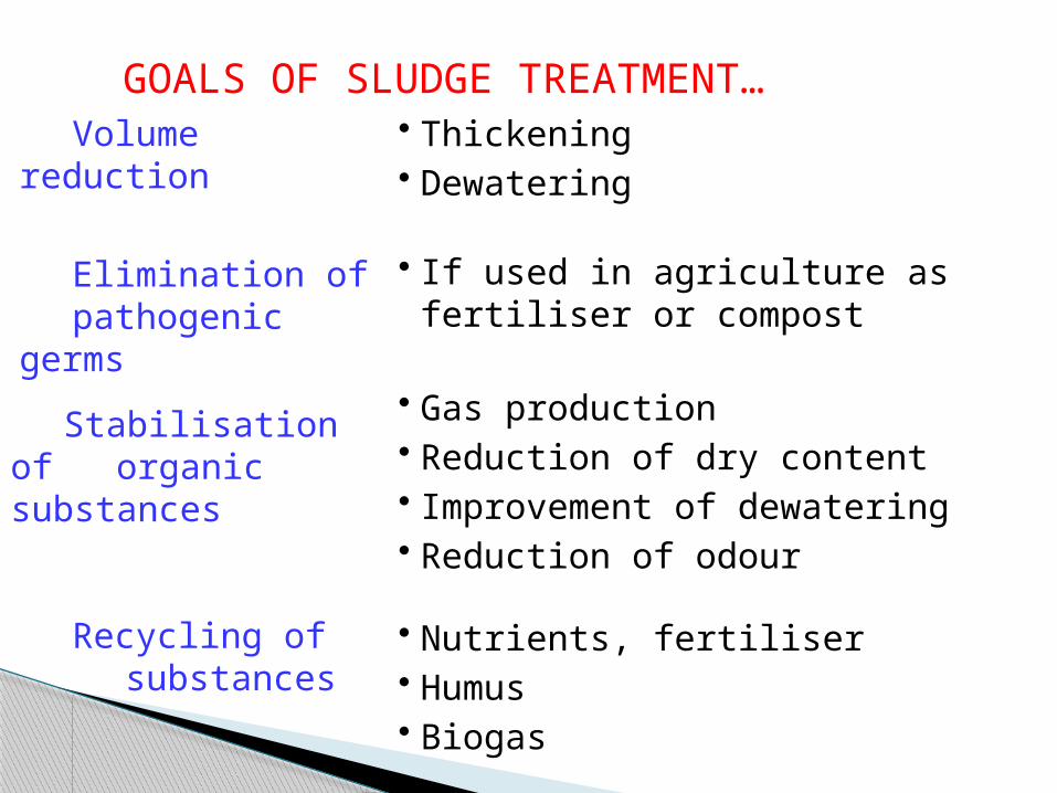
Volume reduction
Elimination of pathogenic
germs
Stabilisation of organic substances
Recycling of
substances
• Thickening • Dewatering
• If used in agriculture as fertiliser or compost
• Gas production • Reduction of dry content • Improvement of dewatering • Reduction of odour
• Nutrients, fertiliser • Humus • Biogas
GOALS OF SLUDGE TREATMENT…
Sludge handling and disposal includes:-
Collection of sludge Transportation of sludge Processing of sludge to convert it to a form
suitable for disposal Final disposal of the sludge
Sludge from plain sedimentation tank- settable solids (raw sludge)
This gray in color contain garbage, fecal solids, debris.
Bad odor. From sec. settling tank following a trickling
filter consists of partially decomposed organic matter.
Dark brown in color, less odor than raw sludge.
Composition…
Primary sludge 3 to 8 % solids About 70% organic material
Sec. sludge Wasted microbes and inert materials 90% organic material
Tertiary sludge If sec. clarifier is used to remove phosphate, this
sludge contain chemical precipitates.
Sludge types…
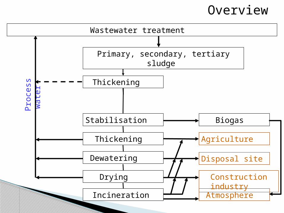
Overview
Thickening
Thickening
Stabilisation
Dewatering
Drying
Incineration
Pro
cess
wa
ter
Biogas
Agriculture
Disposal site
Atmosphere
Wastewater treatment
Primary, secondary, tertiary sludge
Construction industry
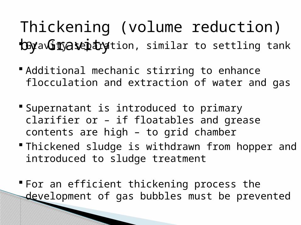
Thickening (volume reduction) by Gravity Gravity separation, similar to settling tank
Supernatant is introduced to primary clarifier or – if floatables and grease contents are high – to grid chamber
Additional mechanic stirring to enhance flocculation and extraction of water and gas
Thickened sludge is withdrawn from hopper and introduced to sludge treatment
For an efficient thickening process the development of gas bubbles must be prevented
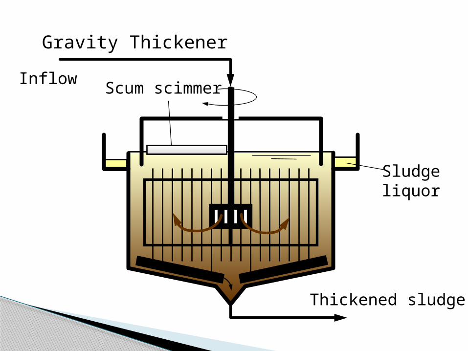
Gravity Thickener
Thickened sludge
Scum scimmerInflow
Sludgeliquor
Thickening by FlotationPre treatment: mostly chemical flocculation
Air bubbles attach to solid particles
Sludge is placed in contact with air-saturated water (full flow or recycle pressurization)
Floating Sludge bubble composite is collected at the surface
Water is recovered under a scum baffle and removed
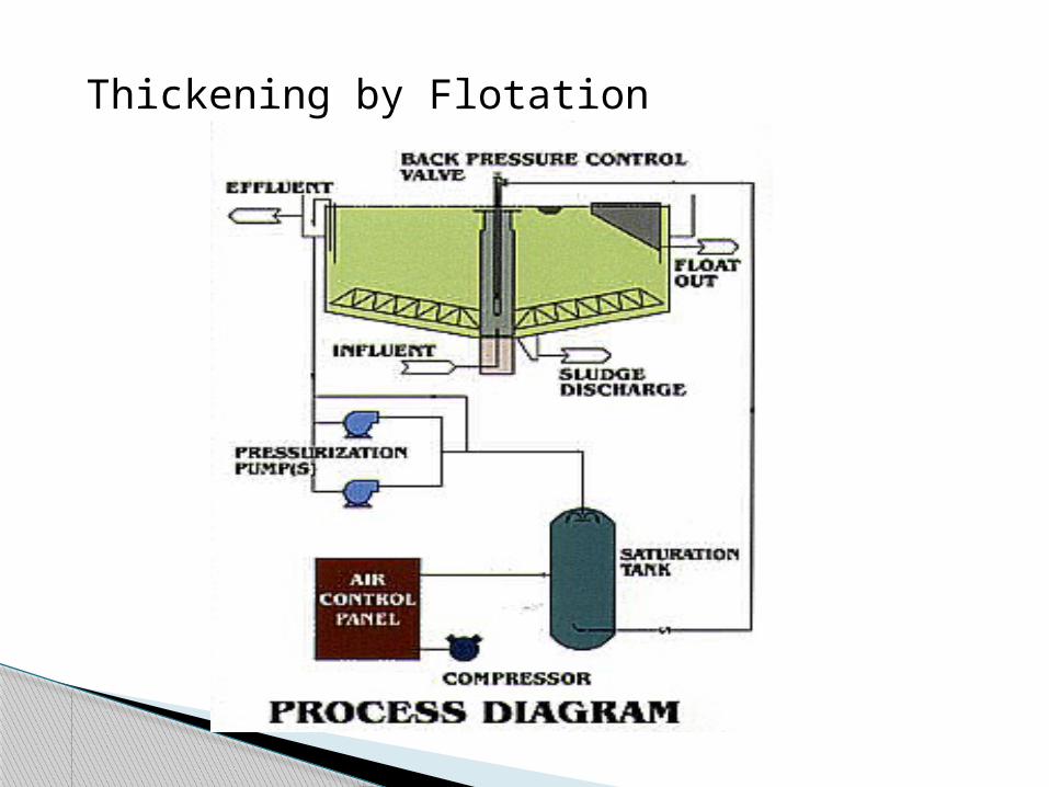
Thickening by Flotation
Aerobic digestion Anaerobic digestion
Aerobic sludge digestion may be used to treat only Waste activated sludge Mixtures of waste activated siudge and primary
siudge Activated sludge treatment plant without primary
settling
Sludge stabilization (mass reduction)
Volatile solids reduction is equal that obtained anaerobically
Lower BOD concentrations in supernatant liquor
Production of an odorless, humus-like, biologically stable end
Operation is relativeluy easy Lower capital cost
Advantages
A high power cost is associated with supplying the required O2
A digested sludge is produced with poor mechanical dewatering characteristics
A useful by-product such as methane is not recovered
Disadvantages
Factors taht must be considered in designing
aerobic digesters include;
Solid reduction
Hydraulic retention time
Oxygen requirements
Energy requirements for mixing
environmental condition such as pH,
temperature.
Process design
Sludge held without aeration for 10-90 days
Process can be accelerated by heating to 35-40oC
These are called High Rate Digesters (10-20 days)
Advantages low solids production useable methane gas produced
Disadvantages high capital costs susceptibility to shocks and overloads
Anaerobic digestion
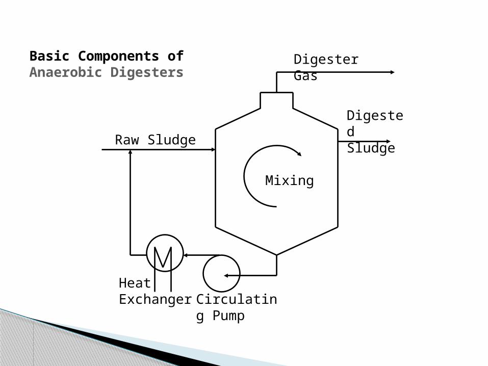
Raw Sludge
Heat Exchanger Circulating
Pump
Digester Gas
Digested Sludge
Mixing
Basic Components of Anaerobic Digesters
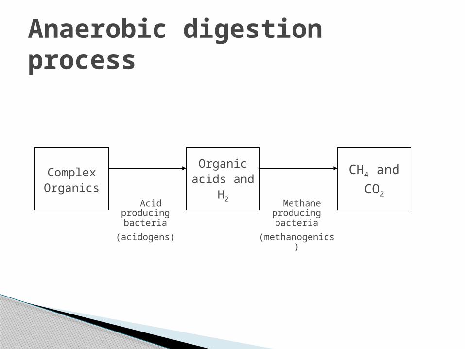
Anaerobic digestion process
Complex Organics
CH4 and
CO2
Organic acids and
H2 Acid producing bacteria
(acidogens)
Methane producing bacteria
(methanogenics)
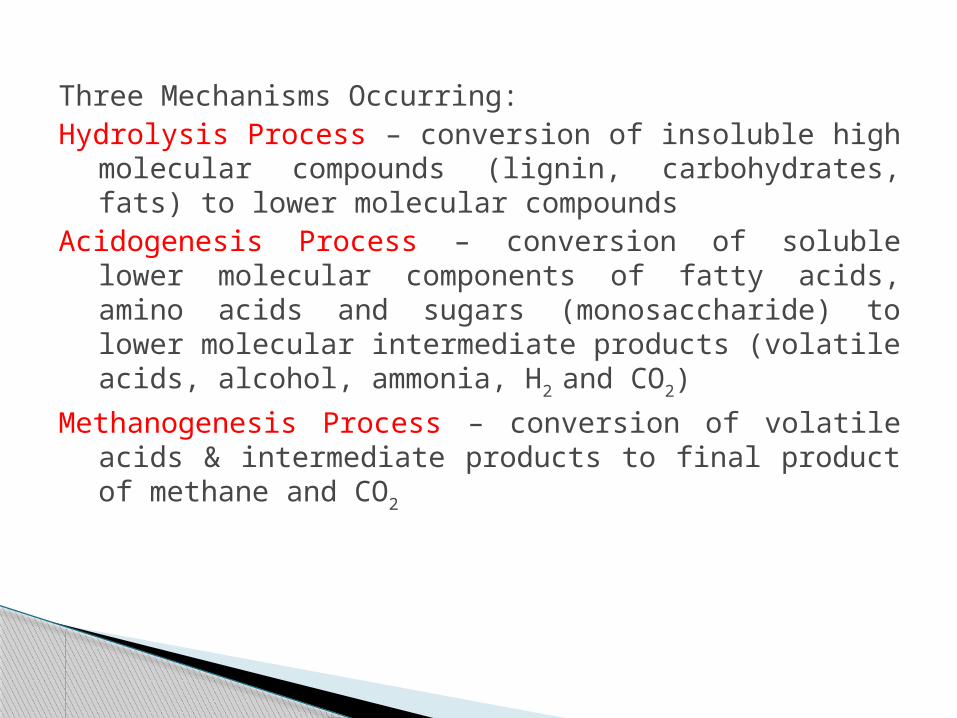
Three Mechanisms Occurring:Hydrolysis Process – conversion of insoluble high
molecular compounds (lignin, carbohydrates, fats) to lower molecular compounds
Acidogenesis Process – conversion of soluble lower molecular components of fatty acids, amino acids and sugars (monosaccharide) to lower molecular intermediate products (volatile acids, alcohol, ammonia, H2 and CO2)
Methanogenesis Process – conversion of volatile acids & intermediate products to final product of methane and CO2
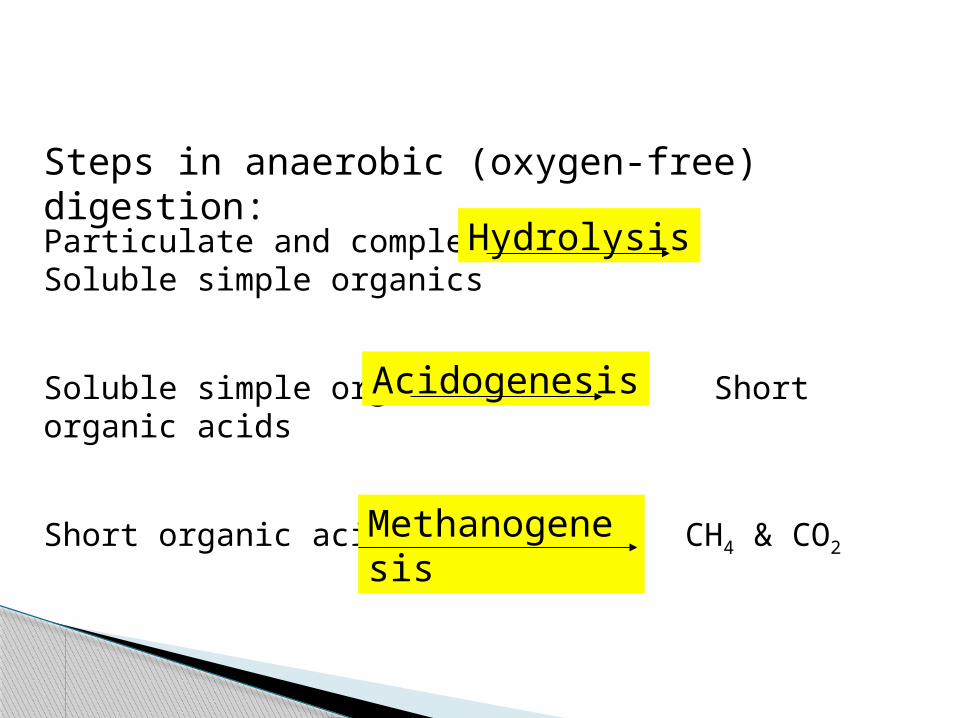
Particulate and complex organics Soluble simple organics
Soluble simple organics Short organic acids
Short organic acids CH4 & CO2
Hydrolysis
Acidogenesis
Methanogenesis
Steps in anaerobic (oxygen-free) digestion:
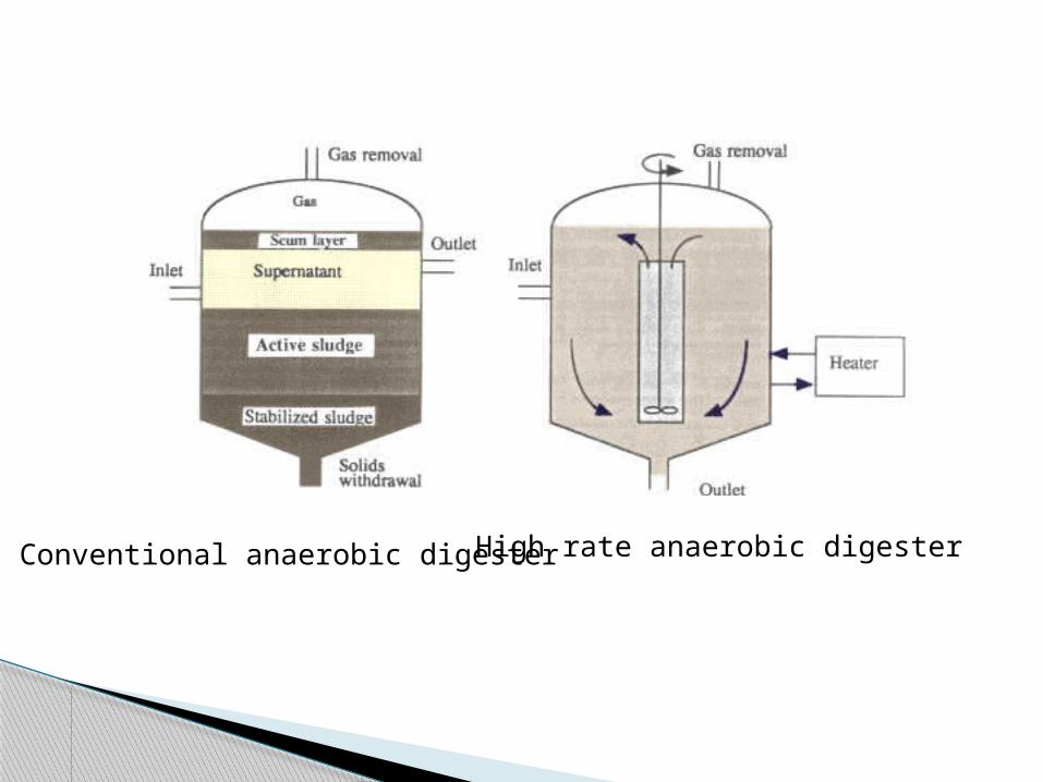
Conventional anaerobic digesterHigh rate anaerobic digester
Mean Cell Residence Time Volumetric Loading Factor Observed Volume Reduction Loading Factors Based on Populations
Anaerobic Digester Design

Dewatering aims to reduce the water content further.
The sludge can then be handled like a solid.
Dewatering can be done mechanically using a filter press (employing pressure or vacuum), or a centrifuge.
Also be done using drying beds.
Sludge dewatering
Most popular methods. A drying bed consists of a 30 cm bed of
sand with an under-drainage . Sludge is applied on the sand bed and is
allowed to dry by evaporation and drainage of excess water over a period of several weeks depending on
climatic conditions.
Drying beds
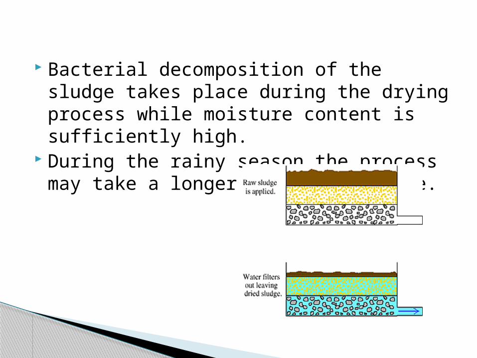
Bacterial decomposition of the sludge takes place during the drying process while moisture content is sufficiently high.
During the rainy season the process may take a longer time to complete.