Embed Size (px)
Citation preview
12 Vol. 2 | No.2 | 2020 | Research and Application of Materials Science
Copyright © 2020 by author(s) and Viser Technology Pte. Ltd. This is an Open Access article distributed under the terms of the Creative Commons Attribution-NonCommercial 4.0 International License (http://creativecommons.org/licenses/by-nc/4.0/), permitting all non-commercial use, distribution, and reproduction in any medium, provided the original work is properly cited.
Viser Technology Pte. Ltd. Research and Application of Materials Science doi: 10.33142/rams.v2i2.3167
Research Article Open Access
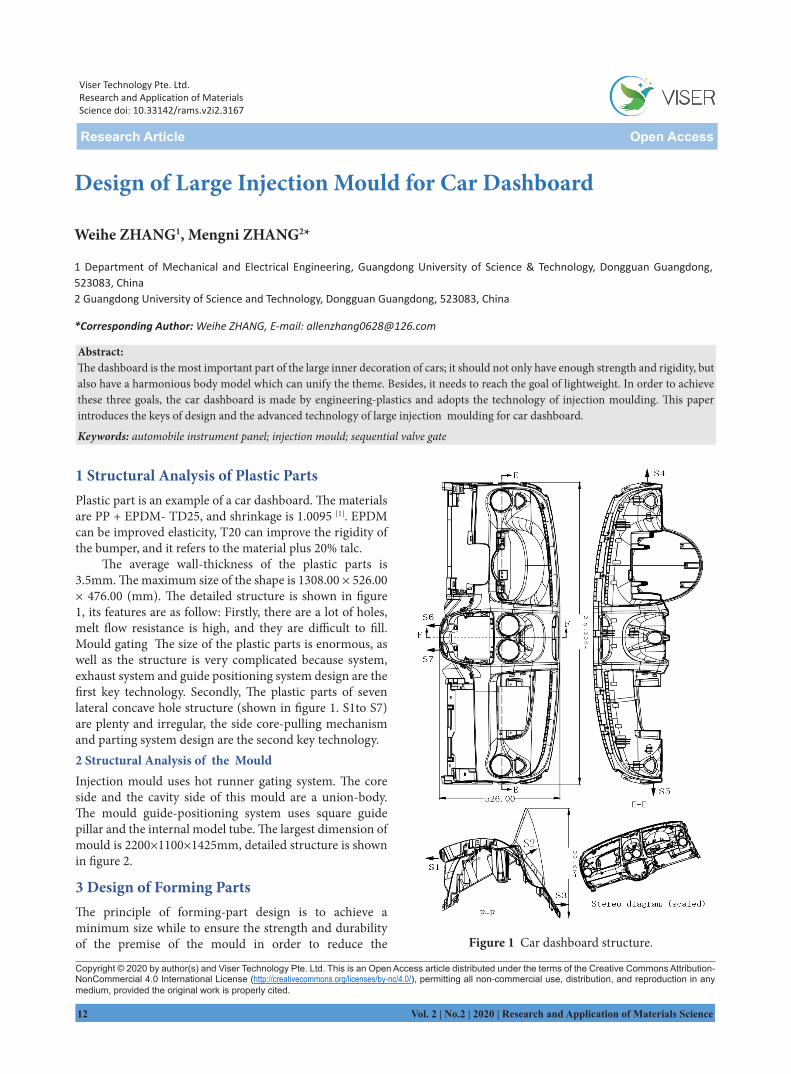
1 Structural Analysis of Plastic PartsPlastic part is an example of a car dashboard. The materialsare PP + EPDM- TD25, and shrinkage is 1.0095 [1]. EPDMcan be improved elasticity, T20 can improve the rigidity ofthe bumper, and it refers to the material plus 20% talc.
The average wall-thickness of the plastic parts is 3.5mm. The maximum size of the shape is 1308.00 × 526.00× 476.00 (mm). The detailed structure is shown in figure1, its features are as follow: Firstly, there are a lot of holes,melt flow resistance is high, and they are difficult to fill.Mould gating The size of the plastic parts is enormous, aswell as the structure is very complicated because system,exhaust system and guide positioning system design are the first key technology. Secondly, The plastic parts of sevenlateral concave hole structure (shown in figure 1. S1to S7)are plenty and irregular, the side core-pulling mechanismand parting system design are the second key technology.2 Structural Analysis of the MouldInjection mould uses hot runner gating system. The coreside and the cavity side of this mould are a union-body.The mould guide-positioning system uses square guidepillar and the internal model tube. The largest dimension of mould is 2200×1100×1425mm, detailed structure is shownin figure 2.
3 Design of Forming PartsThe principle of forming-part design is to achieve aminimum size while to ensure the strength and durabilityof the premise of the mould in order to reduce the
Design of Large Injection Mould for Car Dashboard
Weihe ZHANG1, Mengni ZHANG2*
1 Department of Mechanical and Electrical Engineering, Guangdong University of Science & Technology, Dongguan Guangdong, 523083, China2 Guangdong University of Science and Technology, Dongguan Guangdong, 523083, China
*Corresponding Author: Weihe ZHANG, E-mail: [email protected]
Abstract: The dashboard is the most important part of the large inner decoration of cars; it should not only have enough strength and rigidity, but also have a harmonious body model which can unify the theme. Besides, it needs to reach the goal of lightweight. In order to achievethese three goals, the car dashboard is made by engineering-plastics and adopts the technology of injection moulding. This paperintroduces the keys of design and the advanced technology of large injection moulding for car dashboard.
Keywords: automobile instrument panel; injection mould; sequential valve gate
Figure 1 Car dashboard structure.
Research and Application of Materials Science | Vol. 2 | No.2 | 2020 13
manufacturing cost and production costs [2].Dashboard is a large plastic part with a complex
structure. Mould is a large injection mould, and the parting surfaces are complex. In order to improve the stiffness and strength and to reduce the size, the mould template and moulded parts are designed to be integrated and inserted through all the holes which are greater than the angle of 7 °. Given to the four corners of the template in the template notch protruding insert move, aimed at preventing a given template dislocation deformation, increasing the rigidity and strength of the mould.
Appearance of the dashboard surface must be processed striae, and drafts of the product side must be greater than or equal to 5 °, otherwise the plastic parts
cannot be out of the mould.The fixed mould material is 2311, and the core material
is P20. All cavity surface nitriding treatment should be carried out in order to improve the precision plastic parts and service life.
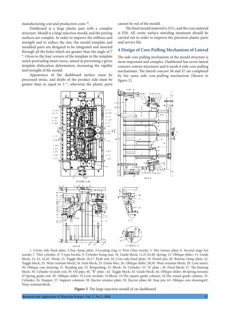
4 Design of Core Pulling Mechanism of LateralThe side core pulling mechanism of the mould structure is most important and complex. Dashboard has seven lateral concave-convex structures and it needs 6 side core-pulling mechanisms. The lateral concave S6 and S7 are completed by the same side core-pulling mechanism (Shown in figure 2).
1. Cavity side fixed plate; 2.Top clamp plate; 3.Locating ring; 4. First Class nozzle; 5. Hot runner plate; 6. Second stage hot nozzle; 7. Thin cylinder; 8. T-type buckle; 9. Cylinder fixing seat; 10. Guide block; 11,27,45,48. Spring; 12. Oblique slider; 13. Guide block; 14, 21, 41,63. Hook; 15. Toggle block; 16,17. Push rod; 18. Core side fixed plate; 19. Dowel pin; 20. Bottom clamp plate; 22. Toggle block; 23. Wear resistant block; 24. limit block; 25. Guide bloc; 26. Oblique slider; 28,50. Wear resistant block; 29. Core insert; 30. Oblique core drawing; 31. Bending pin; 32. Briquetting; 33. Block; 34. Cylinder; 35. “A” plate ; 36. Fixed block; 37. The limiting block; 38. Cylinder of push rod; 39. Oil pipe; 40. “B” plate ; 42. Toggle block; 43. Guide block; 44. Oblique slider; 46.Spring mounts; 47.Spring guide rod; 49. Oblique slider; 51.Lock module; 52.Block; 53.The square guide column; 54.The round guide column; 55. Cylinder; 56. Stopper; 57. Support columns; 58. Ejector retainer plate; 59. Ejector plate; 60. Stop pin; 61. Oblique core drawing;62. Wear resistant block.
Figure 2 The large injection mould of car dashboard
14 Vol. 2 | No.2 | 2020 | Research and Application of Materials Science
In this mould, inverted S1, S3, S4 and S5 are the "lateral oblique slider + spring + hook" core pulling mechanism, power source of oblique slide block core pulling is the hook and the spring. Here we should pay special attention to because if the spring did not receive mechanical impact, it will cause fatigue failure. Therefore, for large injection mould, oblique slide block core pulling must not only adopts a spring as power source. Hook structure is shown in figure 2 (e).
S2 is using the side core pulling mechanism with "inverted bending pin + block”, which is composed of oblique core drawing30, bending pin31, core pulling pressing block 32 and block33. The power source of inclined core pulling30 is hydraulic cylinder 34 (Shown infigure 2 (c)).
Inverted S6 and S7 are using the "lateral hydraulic cylinder +T-type buckle" core pulling mechanism, composed of an inclined core pulling in 61 (2 pieces), thin cylinder 7, T-type buckle 8, oil cylinder base 9 and oblique core drawing guide block10. The power source of core pulling is the hydraulic cylinder (Shown in figure 2 (c) and (d)).
In the injection mould for car dashboard, it is better to use nitrogen gas spring and try to avoid using ordinary spring, because spring will be failure and damage the mould after a long time[1].
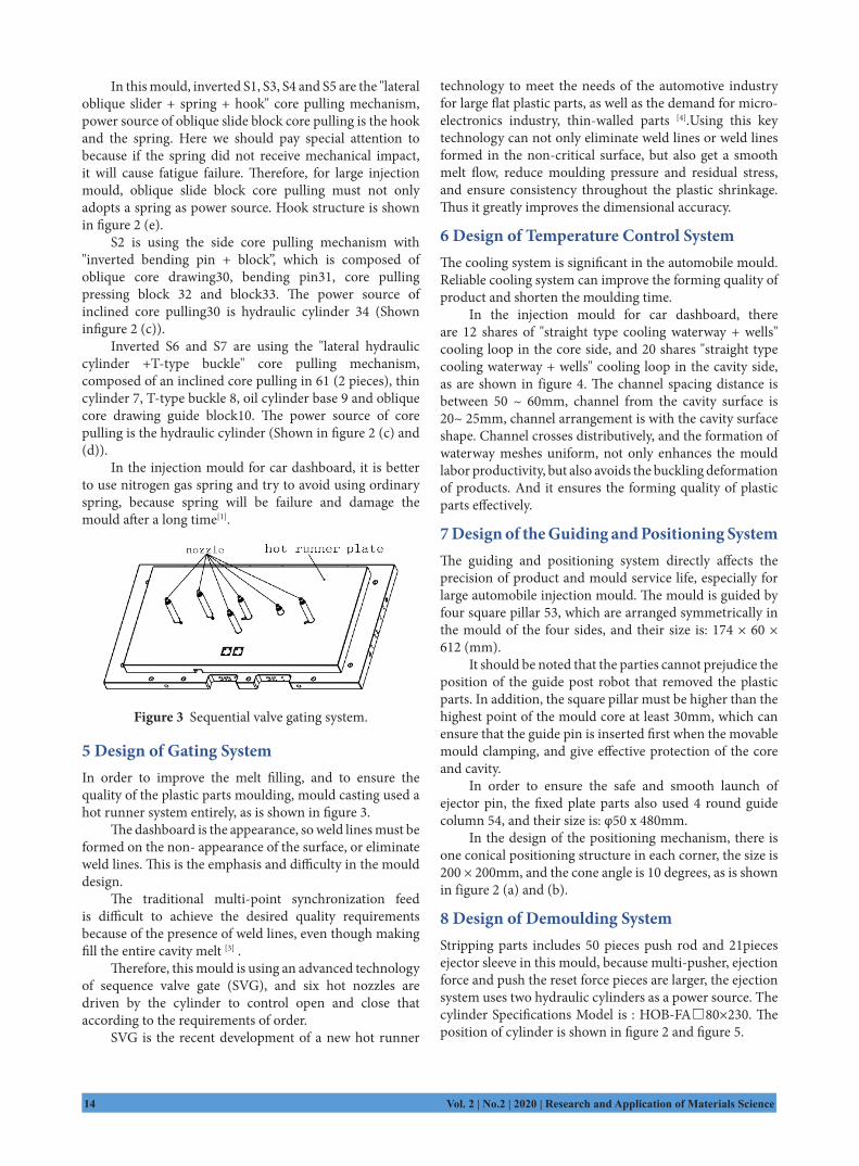
Figure 3 Sequential valve gating system.
5 Design of Gating SystemIn order to improve the melt filling, and to ensure the quality of the plastic parts moulding, mould casting used a hot runner system entirely, as is shown in figure 3.
The dashboard is the appearance, so weld lines must be formed on the non- appearance of the surface, or eliminate weld lines. This is the emphasis and difficulty in the mould design.
The traditional multi-point synchronization feed is difficult to achieve the desired quality requirements because of the presence of weld lines, even though making fill the entire cavity melt [3] .
Therefore, this mould is using an advanced technology of sequence valve gate (SVG), and six hot nozzles are driven by the cylinder to control open and close that according to the requirements of order.
SVG is the recent development of a new hot runner
technology to meet the needs of the automotive industry for large flat plastic parts, as well as the demand for micro- electronics industry, thin-walled parts [4].Using this key technology can not only eliminate weld lines or weld lines formed in the non-critical surface, but also get a smooth melt flow, reduce moulding pressure and residual stress, and ensure consistency throughout the plastic shrinkage. Thus it greatly improves the dimensional accuracy.
6 Design of Temperature Control SystemThe cooling system is significant in the automobile mould. Reliable cooling system can improve the forming quality of product and shorten the moulding time.
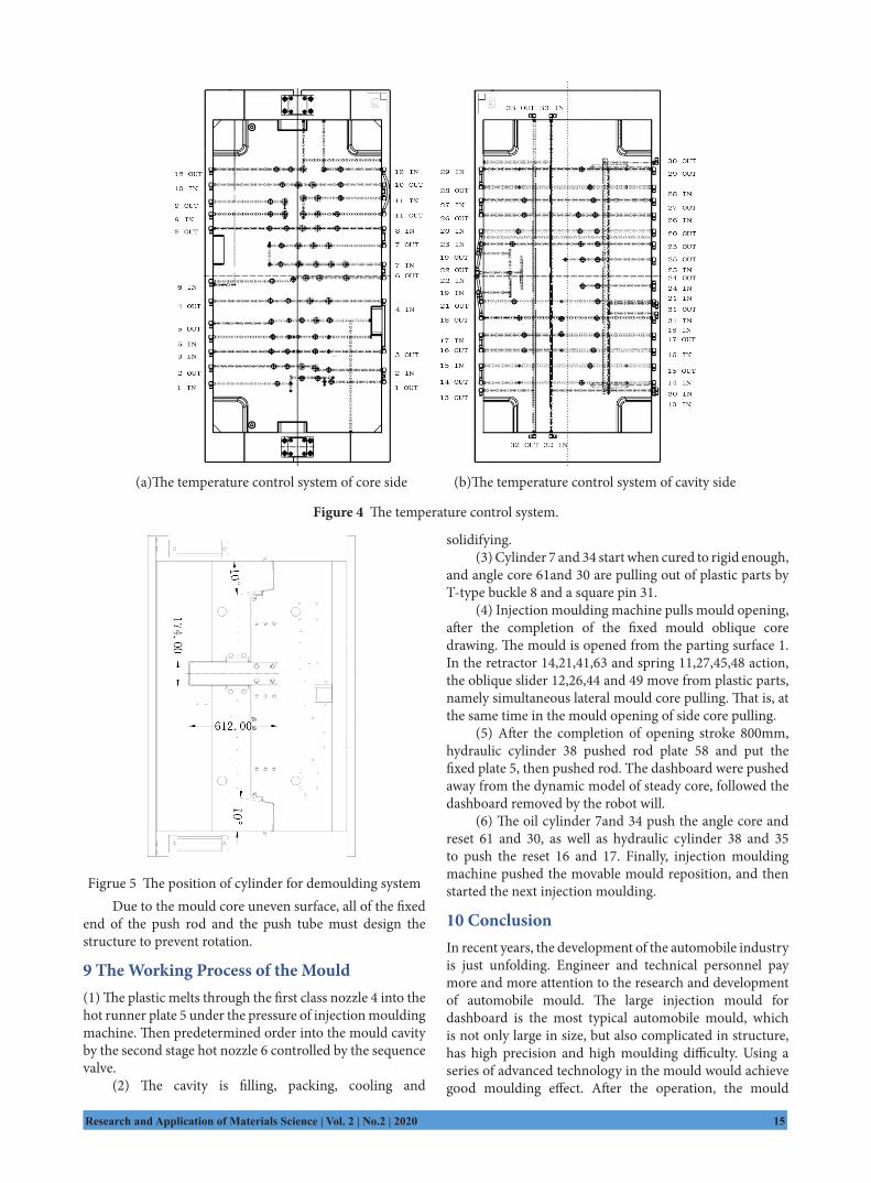
In the injection mould for car dashboard, there are 12 shares of "straight type cooling waterway + wells" cooling loop in the core side, and 20 shares "straight type cooling waterway + wells" cooling loop in the cavity side, as are shown in figure 4. The channel spacing distance is between 50 ~ 60mm, channel from the cavity surface is 20~ 25mm, channel arrangement is with the cavity surface shape. Channel crosses distributively, and the formation of waterway meshes uniform, not only enhances the mould labor productivity, but also avoids the buckling deformation of products. And it ensures the forming quality of plastic parts effectively.
7 Design of the Guiding and Positioning SystemThe guiding and positioning system directly affects the precision of product and mould service life, especially for large automobile injection mould. The mould is guided by four square pillar 53, which are arranged symmetrically in the mould of the four sides, and their size is: 174 × 60 × 612 (mm).
It should be noted that the parties cannot prejudice the position of the guide post robot that removed the plastic parts. In addition, the square pillar must be higher than the highest point of the mould core at least 30mm, which can ensure that the guide pin is inserted first when the movable mould clamping, and give effective protection of the core and cavity.
In order to ensure the safe and smooth launch of ejector pin, the fixed plate parts also used 4 round guide column 54, and their size is: φ50 x 480mm.
In the design of the positioning mechanism, there is one conical positioning structure in each corner, the size is 200 × 200mm, and the cone angle is 10 degrees, as is shown in figure 2 (a) and (b).
8 Design of Demoulding SystemStripping parts includes 50 pieces push rod and 21pieces ejector sleeve in this mould, because multi-pusher, ejection force and push the reset force pieces are larger, the ejection system uses two hydraulic cylinders as a power source. The cylinder Specifications Model is : HOB-FA□80×230. The position of cylinder is shown in figure 2 and figure 5.
Research and Application of Materials Science | Vol. 2 | No.2 | 2020 15
(a)The temperature control system of core side (b)The temperature control system of cavity side
Figure 4 The temperature control system.
Figrue 5 The position of cylinder for demoulding systemDue to the mould core uneven surface, all of the fixed
end of the push rod and the push tube must design the structure to prevent rotation.
9 The Working Process of the Mould(1) The plastic melts through the first class nozzle 4 into the hot runner plate 5 under the pressure of injection moulding machine. Then predetermined order into the mould cavity by the second stage hot nozzle 6 controlled by the sequence valve.
(2) The cavity is filling, packing, cooling and
solidifying.(3) Cylinder 7 and 34 start when cured to rigid enough,
and angle core 61and 30 are pulling out of plastic parts by T-type buckle 8 and a square pin 31.
(4) Injection moulding machine pulls mould opening, after the completion of the fixed mould oblique core drawing. The mould is opened from the parting surface 1. In the retractor 14,21,41,63 and spring 11,27,45,48 action, the oblique slider 12,26,44 and 49 move from plastic parts, namely simultaneous lateral mould core pulling. That is, at the same time in the mould opening of side core pulling.
(5) After the completion of opening stroke 800mm, hydraulic cylinder 38 pushed rod plate 58 and put the fixed plate 5, then pushed rod. The dashboard were pushed away from the dynamic model of steady core, followed the dashboard removed by the robot will.
(6) The oil cylinder 7and 34 push the angle core and reset 61 and 30, as well as hydraulic cylinder 38 and 35 to push the reset 16 and 17. Finally, injection moulding machine pushed the movable mould reposition, and then started the next injection moulding.
10 ConclusionIn recent years, the development of the automobile industry is just unfolding. Engineer and technical personnel pay more and more attention to the research and development of automobile mould. The large injection mould for dashboard is the most typical automobile mould, which is not only large in size, but also complicated in structure, has high precision and high moulding difficulty. Using a series of advanced technology in the mould would achieve good moulding effect. After the operation, the mould
16 Vol. 2 | No.2 | 2020 | Research and Application of Materials Science
action security coordination and the quality of plastic parts reached the requirement of design. The mould of the labor productivity has been improved obviously.
References[1] Zhang Weihe. Injection mould design practical guide [M].
Beijing: Chemical industry press, 2011, 112-148.[2] Zhang Weihe. Injection mould design Practical tutorial
[M]. Beijing: Chemical industry press, 2011, 26-143.[3] Yangbin, liyanjie. Application of CAE technology in
automobile dashboard in mould design [J]. Engineering Plastics Application, 2005, 33(3):61-63.
[4] Guan zheng-qiang. sequential valve gate technology and its application[J].Manufacturing automation, 2010, 32(10), 206-207.
[5] ZHANG Wei-he. Design of Large-sized Injection moulds for Main Bo s of Auto Central Channels[J]. China Plastics.2017:31(05): 92-97.
[6] SUN Xiaoxia, TANG Youliang, ZHANG Jun. Design
of Injection mould for Rearview Mirror Bracket of Automobile with Differential Combined Core-pulling[J]. China Plastics .2018, 32(6): 141-146.
[7] ZHANG Wei-he. Design of injection mould of SVG and secondary ejection for automotive central decoration[J]. Engineering Plastics Application.2017, 46(7): 87-91.
[8] Shen Zhongliang, Zheng Zijun, Xiao Guohua1, Huang Jijun, You Jianguo .Design of IMD Group Mould for Central Control Panel in Automobile[J]. Engineering Plastics Application.2017, 45(1): 70-75.
[9] ZHANG Wei-he. Design of injection mould of SVG and secondary ejection for automotive central decoration[J]. Engineering Plastics Application.2017, 46(7): 87-91.
[10] Caozheng.The Design of Precision Injection mould of Mobile Shell base on mouldflow[J].China Plastic Industry. 2017, 45(05): 65-73.
[11] Cheng Jianling.Design of injection moulds with core-pulling mechanism and Hotrunner system for screwed-bowl-covers[J]. China Plastics , 2015,29(9): 92-96.