Embed Size (px)
Citation preview
Volume No: 1(2014), Issue No: 12 (December) December 2014 www.ijmetmr.com Page 705
ABSTRACT:The significance of the title of the project comes to front with designing structure of a 1000 mt capacity of LPG mounded bullet pressure vessel for static loading, is basically a project concerned with different design variables, thickness of shell, elliptical head, operating manhole and stiffners under load case of high pressure test and working fluid with standards of ASME codes and its assessment is carried out in CATIAV5 for model-ing and analysis in HYPERMESH/ANSYS. it is employed on practical design of LPG pressure vessel as per re-quired by the industry.
INTRODUCTION:A pressure vessel is a closed container designed to hold gases or liquids at a pressure substantially different from the ambient pressure. They are used to store flu-ids under pressure. The pressure vessels are designed with great care because rupture of pressure vessels means an explosion which may cause loss of life and property. The material of pressure vessels may be brit-tle such that cast iron or ductile such as mild steel. And pressure vessels are classified mainly into two types, (a) According to Dimensions (b) According to end Construction.The pressure vessels, according to the dimensions are classified as thin and thick shells. The ratio of internal diameter and wall thickness is the fac-tor which differentiates between thin and thick shells. If the ratio d/t is more than 10, then it is called thin shell and if this ratio is less than 10 it is said to be thick shell. The examples of the thin shells are pipes, boilers and storage tanks while the thick shells are used in pres-sure cylinders, Gun barrels, etc.The pressure vessels ac-cording to end construction are classified as open end and closed end. A simple cylinder whit a piston is an example of closed end vessel. In case of open end ves-sels the circumferential stress is induced in addition to the circumferential stress.
R. Datha SatyanarayanaP.G Student,
Department of Mechanical Engineering,Chaitanya College of Engineering.
I. Satyanarayanaprofessor,
Department of Mechanical Engineering, Chaitanya College of Engineering.
And according to role of process vessels are mainly classified into four types:
(a)Reaction pressure vessel.(b)Heat exchanger pressure vessel.(c)Separation pressure vessel.(d)Storage pressure vessel.
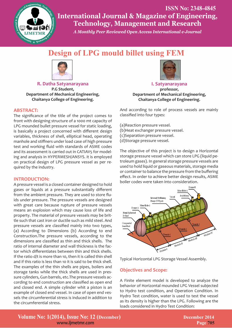
The objective of this project is to design a Horizontal storage pressure vessel which can store LPG (liquid pe-troleum gases). In general storage pressure vessels are used to hold liquid or gaseous materials, storage media or container to balance the pressure from the buffering effect. In order to achieve better design results, ASME boiler codes were taken into consideration.
Typical Horizontal LPG Storage Vessel Assembly.
Objectives and Scope:
A Finite element model is developed to analyze the behavior of Horizontal mounded LPG Vessel subjected to Hydro test condition, and Operation Condition. In Hydro Test condition, water is used to test the vessel as its density is higher than the LPG. Following are the loads considered in Hydro Test Condition:
ISSN No: 2348-4845International Journal & Magazine of Engineering,
Technology, Management and ResearchA Monthly Peer Reviewed Open Access International e-Journal
Design of LPG mould billet using FEM

Volume No: 1(2014), Issue No: 12 (December) December 2014 www.ijmetmr.com Page 706
-Pressure inside the vessel.Hydro Test Pressure.Pressure Due to Head (100 % head of water).-External Pressure on the vessel.-Self weight due to gravity.
In Operating Condition, LPG is used and the vessel is subjected to varying pressure at different heads as 25%, 50%, 75%, 90%. Following are the loads considered in Operating Condition:
-Internal Pressure-Pressure due to head (25%, 50%, 75%, 90%)-External pressure
-Mound pressure at dome ends-Mound pressure on cylinder-Self weight due to gravity.
The Primary Objective of this research is to build a pres-sure vessel with design parameters and to validate the results using finite element method. Scope of design-ing a pressure vessel covers the design basis for follow-ing equipment:
-Vessel-Stiffeners-Domes / Hemispherical D-ends-Sand filling in differential settlements.-Man-holes-Pad-PlatesDesign of Pressure Vessel
2.1 Codes and Standards:
Following are the codes and standards had been used to design the Horizontal pressure vessel:ASME SEC. VIII DIV.1 /For Pressure vesselsIS: 2825
ASME SEC. VIII DIV.2 For Pressure vessels (Selectively for highpressure / high thickness / critical service)
ASME SEC. VIII DIV.2 For Storage Spheres
ASME SEC. VIII DIV.3 For Pressure vessels (Selectively for high pressure)
2.2 Types of Storage Vessels:
2.2.1 Selection of storage vessel type:
In addition to mounded storage, other types of vessel may also be used to store LPG under pressure at ambi-ent temperature.
•Spheres
•Bullets (above ground)
•Submerged storage vessels
The principle of the design of the vessel is that the axi-symmetrical loads are carried by the shell plates, while bending stresses due to non-symmetrical loads are car-ried by the shell plates, while bending stresses due to non-axisymmetrical loads are carried by stiffening rings (except for small diameter, unstiffened vessels).
MINIMUM SHELL/HEAD THICKNESS
Minimum thickness shall be as given belowa) For carbon and low alloy steel vessels- 6mm (Includ-ing corrosion allowance not exceeding 3.0mm), but not less than that calculated as per following:For diameters less than 2400mmWall thickness = Dia/1000 +1.5 + Corrosion AllowanceFor diameters 2400mm and aboveWall thickness = Dia/1000 +2.5 + Corrosion AllowanceAll dimensions are in mm.b) For stainless steel vessel and high alloy vessels -3 mm, but not less than that calculated as per following for diameter more than 1500mm.Wall thickness (mm) = Dia/1000 + 2.5Corrosion Allowance, if any shall be added to minimum thickness.c) Tangent to Tangent height (H) to Diameter (D) ratio (H/D) greater than 5 shall be considered as column and designed accordingly.
ISSN No: 2348-4845International Journal & Magazine of Engineering,
Technology, Management and ResearchA Monthly Peer Reviewed Open Access International e-Journal

Volume No: 1(2014), Issue No: 12 (December) December 2014 www.ijmetmr.com Page 707
d) For carbon and low alloy steel columns / towers -8mm (including corrosion allowance not exceeding 3.0mm.e) For stainless steel and high alloy columns / towers -5mm. Corrosion allowance, if any, shall be added to minimum thickness.
2.3.2 Vessel sizing:
All Stiffeners Based on inside diameterAll Clad/Lined Vessels Based on inside diameterVessels (Thickness>50mm) Based on inside diameterAll Other Vessels Based on outside diameterTanks & Spheres Based on inside diameterFE Model Preparation / Results:
Mesh is created using hypermesh, and an average ele-ment size of 20 mm is used for modeling. Hexa / Penta element configurations are used in building this model. And to capture the surfaces stresses, we had extracted skin as shell elements.
Boundary Conditions (Hydro Test Condition):
4.2.1 Constraints:
Vessel is supported by the Sand fill, and sand fill is con-structed on the ground, hence all the base nodes of the mound are constrained in all degrees of freedom (123456). The arrow marks detailed below represents constraints on the base.
Fig: 4.4 Constraints (SPC loactions)
Since the vessel is installed on the ground, Gravity of 9810 mm /s2 has been considered over the entire mod-el. Other Boundary conditions are loads applied inter-nally and externally. Below are the details of other load cases carried out to find the performance of the Vessel Design.
Pressures inside the Vessel:
With regard to the stiffener design, the internal pres-sure only affects the normal force N3 in the stiffening ring, not the bending moment of the shear force. Part of the shell plates will act together with the ring to car-ry the load to which the rings are subjected. This part, the working width w, is:w = 2 x 0.78 x √(R x t)The internal pressure, acting on the working width, will cause a normal tensile load N3 which is carried by the combination of stiffening ring and working width of the shell plate.N3 = p3 x w x RWhere p3 = the internal design pressure.Hydro Test Pressure : 19.75 kg/cm2 or 1.93668 MPaPressure due to head : 0.75 kg/cm2 or 0.073575 MPa(at 100% head of water)
ISSN No: 2348-4845International Journal & Magazine of Engineering,
Technology, Management and ResearchA Monthly Peer Reviewed Open Access International e-Journal
Volume No: 1(2014), Issue No: 12 (December) December 2014 www.ijmetmr.com Page 708
4.2.3 Pressure outside the Vessel:
External Pressure : 1.856 kg/cm2 or 0.1819994 MPaGravity is considered to capture the self weight of the vessel.
4.3 Boundary Conditions (internal pressure + liquid weight + mound weight + load due to thermal expansion with center soft) at Oper-ating Conditions:
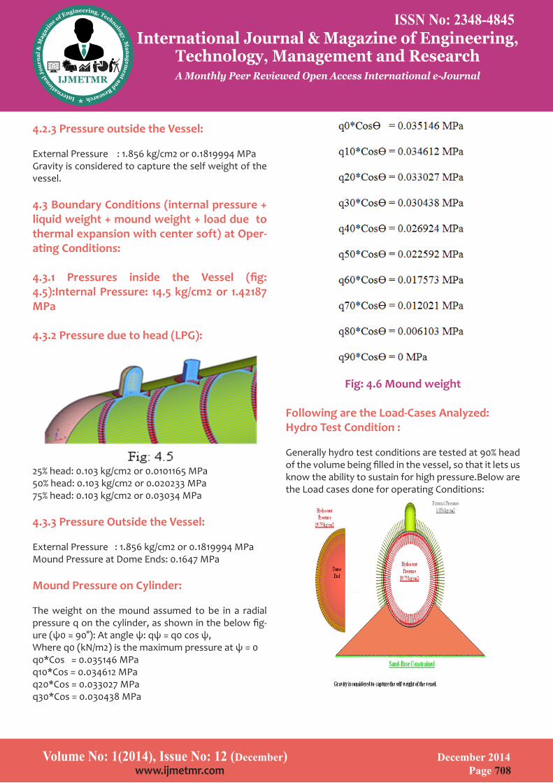
4.3.1 Pressures inside the Vessel (fig: 4.5):Internal Pressure: 14.5 kg/cm2 or 1.42187 MPa
4.3.2 Pressure due to head (LPG):
25% head: 0.103 kg/cm2 or 0.0101165 MPa50% head: 0.103 kg/cm2 or 0.020233 MPa75% head: 0.103 kg/cm2 or 0.03034 MPa
4.3.3 Pressure Outside the Vessel:
External Pressure : 1.856 kg/cm2 or 0.1819994 MPaMound Pressure at Dome Ends: 0.1647 MPa
Mound Pressure on Cylinder:
The weight on the mound assumed to be in a radial pressure q on the cylinder, as shown in the below fig-ure (ψ0 = 90°): At angle ψ: qψ = q0 cos ψ,Where q0 (kN/m2) is the maximum pressure at ψ = 0 q0*Cos = 0.035146 MPa q10*Cos = 0.034612 MPa q20*Cos = 0.033027 MPa q30*Cos = 0.030438 MPa
Fig: 4.6 Mound weight
Following are the Load-Cases Analyzed:Hydro Test Condition :
Generally hydro test conditions are tested at 90% head of the volume being filled in the vessel, so that it lets us know the ability to sustain for high pressure.Below are the Load cases done for operating Conditions:
ISSN No: 2348-4845International Journal & Magazine of Engineering,
Technology, Management and ResearchA Monthly Peer Reviewed Open Access International e-Journal
Volume No: 1(2014), Issue No: 12 (December) December 2014 www.ijmetmr.com Page 707
d) For carbon and low alloy steel columns / towers -8mm (including corrosion allowance not exceeding 3.0mm.e) For stainless steel and high alloy columns / towers -5mm. Corrosion allowance, if any, shall be added to minimum thickness.
2.3.2 Vessel sizing:
All Stiffeners Based on inside diameterAll Clad/Lined Vessels Based on inside diameterVessels (Thickness>50mm) Based on inside diameterAll Other Vessels Based on outside diameterTanks & Spheres Based on inside diameterFE Model Preparation / Results:
Mesh is created using hypermesh, and an average ele-ment size of 20 mm is used for modeling. Hexa / Penta element configurations are used in building this model. And to capture the surfaces stresses, we had extracted skin as shell elements.
Boundary Conditions (Hydro Test Condition):
4.2.1 Constraints:
Vessel is supported by the Sand fill, and sand fill is con-structed on the ground, hence all the base nodes of the mound are constrained in all degrees of freedom (123456). The arrow marks detailed below represents constraints on the base.
Fig: 4.4 Constraints (SPC loactions)
Since the vessel is installed on the ground, Gravity of 9810 mm /s2 has been considered over the entire mod-el. Other Boundary conditions are loads applied inter-nally and externally. Below are the details of other load cases carried out to find the performance of the Vessel Design.
Pressures inside the Vessel:
With regard to the stiffener design, the internal pres-sure only affects the normal force N3 in the stiffening ring, not the bending moment of the shear force. Part of the shell plates will act together with the ring to car-ry the load to which the rings are subjected. This part, the working width w, is:w = 2 x 0.78 x √(R x t)The internal pressure, acting on the working width, will cause a normal tensile load N3 which is carried by the combination of stiffening ring and working width of the shell plate.N3 = p3 x w x RWhere p3 = the internal design pressure.Hydro Test Pressure : 19.75 kg/cm2 or 1.93668 MPaPressure due to head : 0.75 kg/cm2 or 0.073575 MPa(at 100% head of water)
ISSN No: 2348-4845International Journal & Magazine of Engineering,
Technology, Management and ResearchA Monthly Peer Reviewed Open Access International e-Journal
Volume No: 1(2014), Issue No: 12 (December) December 2014 www.ijmetmr.com Page 708
4.2.3 Pressure outside the Vessel:
External Pressure : 1.856 kg/cm2 or 0.1819994 MPaGravity is considered to capture the self weight of the vessel.
4.3 Boundary Conditions (internal pressure + liquid weight + mound weight + load due to thermal expansion with center soft) at Oper-ating Conditions:
4.3.1 Pressures inside the Vessel (fig: 4.5):Internal Pressure: 14.5 kg/cm2 or 1.42187 MPa
4.3.2 Pressure due to head (LPG):
25% head: 0.103 kg/cm2 or 0.0101165 MPa50% head: 0.103 kg/cm2 or 0.020233 MPa75% head: 0.103 kg/cm2 or 0.03034 MPa
4.3.3 Pressure Outside the Vessel:
External Pressure : 1.856 kg/cm2 or 0.1819994 MPaMound Pressure at Dome Ends: 0.1647 MPa
Mound Pressure on Cylinder:
The weight on the mound assumed to be in a radial pressure q on the cylinder, as shown in the below fig-ure (ψ0 = 90°): At angle ψ: qψ = q0 cos ψ,Where q0 (kN/m2) is the maximum pressure at ψ = 0 q0*Cos = 0.035146 MPa q10*Cos = 0.034612 MPa q20*Cos = 0.033027 MPa q30*Cos = 0.030438 MPa
Fig: 4.6 Mound weight
Following are the Load-Cases Analyzed:Hydro Test Condition :
Generally hydro test conditions are tested at 90% head of the volume being filled in the vessel, so that it lets us know the ability to sustain for high pressure.Below are the Load cases done for operating Conditions:
ISSN No: 2348-4845International Journal & Magazine of Engineering,
Technology, Management and ResearchA Monthly Peer Reviewed Open Access International e-Journal

Volume No: 1(2014), Issue No: 12 (December) December 2014 www.ijmetmr.com Page 709
Fig:4.7a HydroTest Condition
Load Case-1: Internal Pressure + liquid weight + mound weight + Load due to thermal expansion with centre soft.
LoadCase-2: Internal pressure + liquid weight + mound weight + Load due to thermal expansion with end soft.
LoadCase-3: liquid weight + mound weight + Load due to thermal expansion with centre soft.
LoadCase-4: liquid weight + mound weight + Load due to thermal expansion with end soft.
Fig: 4.7b LoadCases - 1 to 4
4.5 SCL: Stress Classification Lines:This SCL information gives various details across the cross-sectional thickness, mainly these scl plots are de-tailed in the welding regions. So that we can calculate the strength of the weld joint in the vessel to ensure that there are no pressure leakages. These plots are defined by displacement in X-Dir and Stress in Y-Dir.
SCL Plots at various junctions are defined below and each SCL plot had been compared with the allowable stress at those maximum points in the below locations :SCL-1 : Dome to ShellSCL-2 : Shell to NozzleSCL-3 : Shell to stiffeners at endsSCL-4 : Shell to Stiffeners-at centerSCL-5 : Shell to Dome-A
SCL Locations:
Fig: 4.8 SCL Loacations
SCL’s had been plotted from the above some locations where the stress are maximum. Hence the analyst has to take SCL at all critical location near discontunity. With experience and looking at geometry and stress contour, and expert will be able to make out which SCL gives maximum membrane or bending stress. In oth-er words considering that SCL which gives maximum membrane and bending stress to arrive at PL or Q as the case may be helpful.
4.6 Results: HYDRO –TEST Condition:
Displacement & Stress Contours at 90% LPG Head:
Z-Displacement at 100 % water filled condi-tion:
ISSN No: 2348-4845International Journal & Magazine of Engineering,
Technology, Management and ResearchA Monthly Peer Reviewed Open Access International e-Journal
Volume No: 1(2014), Issue No: 12 (December) December 2014 www.ijmetmr.com Page 710
Fig: 4.9b Stress Plot (Hydro Test Condition)
Overall Stress contour at Yield Strength (345 MPa):
Fig: 4.10a Overall Stress Plot (Hydro Test Condition)The stresses above the allowable limit are
in red ranging from 345-639 MPa.
Fig: 4.10b Stresses between Domes(A&B) to Vessel (Hydro Test Condition) with pad plates.
Above stress between Dome A to Vessel and Dome B to Vessel. These are the locations where the stresses are very high and above the yield limit, but below the ultimate stress for the material being used. To reduce the stresses over this region, pad plates are used.
ISSN No: 2348-4845International Journal & Magazine of Engineering,
Technology, Management and ResearchA Monthly Peer Reviewed Open Access International e-Journal

Volume No: 1(2014), Issue No: 12 (December) December 2014 www.ijmetmr.com Page 711
Fig: 4.11 Stresses between Domes to Vessel (Hydro Test Condition) without pad plates.
A localized stress is formed below the pad plates. (Max Stress: 639 MPa) Stress contour at allowable stress (205 Mpa) for stiffeners:
4.12 Stress Plots in Stiffener locations
Stiffeners are in allowable range at 100%head+Hydro Test Pressure. Except in the regions of stiffeners just below the pad-plates. Thus there is a local stress which is less than the minimum yield strength (< 345MPa).
SCL Info for Hydro Test Condition:
4.13 SCL plots for Hydro Test Condition.Summary of SCL Data extracted for Hydro Test Condition (Table 4.1):
ISSN No: 2348-4845International Journal & Magazine of Engineering,
Technology, Management and ResearchA Monthly Peer Reviewed Open Access International e-Journal
Volume No: 1(2014), Issue No: 12 (December) December 2014 www.ijmetmr.com Page 712
5. CONCLUSION:
Finite element model is developed to analyze the be-havior of Horizontal mounded LPG Vessel subjected to Hydro test condition, and Operation Condition. Aim is to design and validate a pressure vessel that can store 1000 metric tons (MT) of LPG in it (either in gaseous state or in liquid state). SA-537-cl1 material had been used for all components in the model. This design has been validated for various conditions and passed suc-cessfully.
1.Hydro Test Condition: As briefed earlier any pressure vessel constructed shall be tested for Hydro Test as a mandatory. In this test 90% of water will be filled in the vessel and subjected to internal pressure of 19.75 kg/cm2 and an external pressure of 1.85 kg/cm2 (obtained from design calculations) and also self weight due to gravity. Below is the results summary (Table 4.6):
SCL-1 : Dome to VesselSCL-2 : Vessel to NozzleSCL-3 : Vessel to stiffeners at endsSCL-4 : Vessel to Stiffeners-at centerSCL-5 : Vessel to Dome-A/B Whole model cannot be taken into considered for find-ing stresses due to assumptions made to minimize the model to main components of a vessel. Stress inten-sities are calculated in only the welded locations and joints, where the bullet has to sustain for higher stress-es. As per the above table, model is passed for all the membrane and bending stresses ( ~280 MPa < Yield strength 50000 psi / 345 MPa ). All the obtained stress-es for the design are less than the allowable stresses.
Refernces:
1. Dennis Moss, “Pressure vessel design manual”
2. B.S.Thakkar, S.A.Thakkar; “DESIGN OF PRESSURE VESSEL USING ASME CODE, SECTION VIII, IVISION 1”; International Journal of Advanced Engineering Research and Studies, Vol. I, Issue II, January-March, 2012.
3. ASME Boiler and Pressure Vessel Code 2007 Sec 8 Division 1 (2007).
4. American Standard Pipe Diameters;
5. Stresses in Large Horizontal Cylindrical Pressure Ves-sels on Two Saddle Supports by L. P. Zick.Original paper published in September 1951 “THE WELDING JOURNAL RESEARCH SUPPLEMENT.”
6. Location of ‘reboiler return inlet nozzle’ and its ef-fect on Distillation Column [email protected], 005-2009 Process Engineering Services.
7. Optimal wall-thickness of the spherical pressure ves-sel with respect to criterion about minimal mass and equivalent stressdražankozak, josipsertić. ANNALS OF THE FACULTY OF ENGINEERING HUNEDOARA – 2006 TOME IV. Fascicole 2 Understanding How Changes in Pressure Vessel Codes May Impact Pressure Vessel Performance .Patrick J. Sullivan Highlander Engineer-ing Services 2008, PLLC Argyle, NY
8. Results of fea analyses at nozzle/shell junctions sub-jected to external loads steven R. Massey charlie S. HsiehBlack & veatch pritchardInc-2009.
ABOUT AUTHORS:
R.Datha Satyanarayana is a P.G student of Me-chanical Department of Chaitanya Engineering College. He done his B.Tech from ADITYA Engineering College affiliated to Jawaharlal Nehru Technological University Kakinada.
Prof[Dr]I.SATYANARAYANA,B.E.,M.E.,PGDAS.,FIE,FIIP,MISTE,C[ENGG],,born in West Godavari district, Andhra Pradesh, INDIA. He received M.E. [machine de-sign] from Andhra University, VISAKHAPATNAM. AP, INDIA. He is CHAIRMAN of ‘’THE INSTITUTION OF EN-GINEERS [INDIA] VISAKHAPATNAM, centre, He is also a council member of IEI. He has 35 years of industrial experience and 10 years teaching experience as pro-fessor in Mech.Engg..presently he is working as pro-fessor in Mech Engg dept, CHAITANYA ENGG,COLLEGE VISAKHAPATNAM. INDIA
ISSN No: 2348-4845International Journal & Magazine of Engineering,
Technology, Management and ResearchA Monthly Peer Reviewed Open Access International e-Journal


![Pressure Vessel [Design]](https://img.pdfslide.net/doc/110x75/546b26fcb4af9f000e8b4629/pressure-vessel-design-5584556ceffe5.jpg)