Embed Size (px)
Citation preview

EUROPEAN ORGANISATION FOR TECHNICAL APPROVALS
E TAE TA
EUROPEAN ORGANISATION FOR TECHNICAL APPROVALS
TECHNICAL REPORT
Design of Metal Anchors For Use In Concrete
Under Seismic Actions
TR 45Edition February 2013

February 2013
Table of Contents
1 Introduction 3
2 Scope 3
2.1 General ................................................................................................................................................ 3
2.2 Type of anchors, anchor groups and number of anchors ................................................................... 3
2.3 Concrete member................................................................................................................................ 4
2.4 Type of load ......................................................................................................................................... 4
3 Abbreviations and Notation 4
3.1 Abbreviations ....................................................................................................................................... 4
3.2 Indices ................................................................................................................................................. 4
3.3 Superscripts ........................................................................................................................................ 5
3.4 Notation ............................................................................................................................................... 5
3.5 Definitions ............................................................................................................................................ 5
4 Design and safety concept 5
4.1 General ................................................................................................................................................ 5
4.2 Ultimate limit state ............................................................................................................................... 6
4.2.1 Partial safety factor for actions ............................................................................................. 6 4.2.2 Partial safety factor for resistances ...................................................................................... 6
4.3 Damage limitation state ....................................................................................................................... 6
5 Design of anchorages under seismic action 6
5.1 General ................................................................................................................................................ 6
5.2 Seismic performance categories ......................................................................................................... 7
5.3 Design options ..................................................................................................................................... 8
5.4 Design criteria...................................................................................................................................... 8
5.5 Derivation of forces acting on anchors .............................................................................................. 10
5.5.1 General .............................................................................................................................. 10 5.5.2 Addition to EN 1998-1: 2004, 4.3.3.5 ................................................................................. 10 5.5.3 Addition to EN 1998-1:2004, 4.3.5.1 .................................................................................. 10 5.5.4 Additions and alterations to EN 1998-1:2004, 4.3.5.2........................................................ 10 5.5.5 Additions and alterations to EN 1998-1:2004, 4.3.5.4........................................................ 12
5.6 Resistances ....................................................................................................................................... 12
5.6.1 Required verifications ........................................................................................................ 12 5.6.2 Design resistance .............................................................................................................. 12 5.6.3 Interaction – resistance to combined tension and shear loads .......................................... 13
5.7 Displacements ................................................................................................................................... 13
6 Additional proofs for ensuring the characteristic resistance of concrete member 14
7 References 14

EOTA TR 045 Design of metal anchors for use in concrete under seismic action page 2 of 15
February 2013
Tables Table 2.1 Diameter of clearance hole in the fixture Table 5.1 Recommended seismic performance categories for anchors Table 5.2 Values of qa and Aa for non-structural elements Table 5.3 Required verifications Table 5.4 Reduction factor seis
Figures Figure 2.1 Anchorages covered by this design method Figure 5.1 Seismic design by protection of the fastening Figure 5.2 Seismic design by yielding of a ductile anchor – illustration of stretch length Figure 5.3 Vertical effects of the seismic action Figure 5.4 Rotations and anchor displacements

EOTA TR 045 Design of metal anchors for use in concrete under seismic action page 3 of 15
February 2013
1 Introduction This Technical Report contains a design method for anchors which have been awarded an ETA in accordance with ETAG 001 [7], Annex E.
Note: A design method that is consistent with the assessment according to ETAG 001, Annex E has been developed during the revision of the CEN/TS 1992-4 series [1] and is incorporated in EN 1992-4 [4]. Since the design provisions in the CEN/TS 1992-4 series are not consistent with the assessment according to ETAG 001, Annex E and the EN 1992-4 has not yet been published the need for a publicly available document arises. The design method for anchors to resist seismic loading in this Technical Report (TR) is intended to bridge the time span until the publication of EN 1992-4. The design method given in this TR complies with the final draft of EN 1992-4 prepared by CEN/TC 250/SC 2/WG 2 to be submitted for CEN enquiry.
This document should be withdrawn when a) EN 1992-4 is published, and b) all ETAs referring to this Technical Report have reached the end of their validity period.
Once EN 1992-4 has been published no ETA should be issued with reference to this Technical Report in Clause 4 of the ETA.
This document has been written to represent current best practice. However, users should verify that applying its provisions allows local regulatory requirements to be satisfied.
2 Scope
2.1 General
This Technical Report provides a design method for anchors, which are used to transmit seismic actions to concrete members.
This Technical Report is intended for safety relevant applications in which the failure of anchors will result in collapse or partial collapse of the structure, cause risk to human life or lead to significant economic loss.
The provisions in this Technical Report do not apply to the design of anchors placed in critical regions of concrete elements where concrete spalling or yielding of reinforcement might occur during seismic events such as e.g. in plastic hinge zones. Anchors should therefore be placed outside of these regions.
2.2 Type of anchors, anchor groups and number of anchors
This design method applies to the design of post-installed mechanical and bonded fasteners installed in concrete using approved anchors which fulfil the requirements of ETAG 001 [7] (including EOTA TR 018 [8]). Anchors shall be qualified according ETAG 001, Annex E for use in concrete under seismic actions. The anchor capacities in terms of resistances (characteristic values) and displacements are given in the relevant ETA.
The design method is valid for single anchors and anchor groups. In case of an anchor group the loads are applied to the individual anchors of the group by means of a common rigid fixture (e.g. anchor plate). The diameter df of the clearance hole in the fixture should not be larger than the value given in Table 2.1. In an anchor group only anchors of the same type, size and length shall be used.
Anchor configurations as given in Section 1.1 of ETAG 001, Annex C and EOTA TR 029 [9] are covered by this Technical Report. These configurations are also shown in Figure 2.1.
Anchors qualified for multiple use for non-structural applications according to ETAG 001, Part 6 are not covered by this document.
Table 2.1 Diameter of clearance hole in the fixture
external diameter d or dnom1) [mm] 6 8 10 12 14 16 18 20 22 24 27 30
diameter df of clearance hole in the fixture
[mm] 7 9 12 14 16 18 20 22 24 26 30 33
1) diameter d if bolt bears against the fixture; diameter dnom if sleeve bears against the fixture

EOTA TR 045 Design of metal anchors for use in concrete under seismic action page 4 of 15
February 2013
Anchorage situated far from the edge (c ≥ max (10 hef; 60d)) for all loading directions; and anchorage situated close to the edge (c < max (10 hef; 60d)) if loaded in tension only;
Anchorage situated close to the edge (c < max (10 hef; 60d)) for all loading directions
Figure 2.1 Anchorages covered by this design method
2.3 Concrete member
The concrete member should be of normal weight concrete of at least strength class C 20/25 and at most strength class C 50/60 according to EN 206 [6].
2.4 Type of load
The design method applies to anchors subjected to seismic action (see EN 1990 [2] and EN 1998-1 [5]).
3 Abbreviations and Notation
3.1 Abbreviations
C1, C2 = seismic performance categories for prequalification of anchors
DLS = Damage Limitation State (see EN 1998-1:2004 [5], 2.2.1)
ULS = Ultimate Limit State (see EN 1998-1:2004 [5], 2.2.1)
3.2 Indices
M = material
N = tension
R = resistance
S = action
V = shear
c = concrete
cp = concrete pry-out
d = design value
k = characteristic value
p = pull-out
pl = plastic
s = steel
seis = seismic (earthquake)
sp = splitting
u = ultimate
c1, c2 < max (10 hef ; 60 d)
1 … anchors 2 … anchor plate (common fixture)
EOTA TR 045 Design of metal anchors for use in concrete under seismic action page 5 of 15
February 2013
y = yielding
3.3 Superscripts
g = load on or resistance of a group of anchors
h = most loaded anchor of a group
3.4 Notation
Aa = seismic amplification factor
EE,d = design value of the effect of seismic actions as given in EN 1998-1:2004
F = force (resulting force)
FRd (NRd ; VRd) = design value of resistance of a single anchor or an anchor group (axial force, shear force)
FSd (NSd ; VSd) = resulting design value of action on a single anchor or an anchor group (axial load, shear load)
Mpl = plastic moment (yield mechanism)
N = axial force (positive: tension force; negative: compression force)
Rd = design resistance
Rk = characteristic resistance
Sd = design action
V = shear force
c = edge distance
c1 = edge distance in direction 1; in case of anchorages close to an edge loaded in shear c1 is the edge distance in direction of the shear load
c2 = edge distance in direction 2; direction 2 is perpendicular to direction 1
d = diameter of anchor
dnom = outside diameter of anchor
fck,cube = characteristic concrete compressive strength measured on cubes with a side length of 150 mm (value of concrete strength class according to EN 206)
fuk = characteristic steel ultimate tensile strength (nominal value)
fyk = characteristic steel yield tensile strength (nominal value)
hef = effective embedment depth of anchor
= displacement of the anchor
= bond strength
M = partial safety factor for material
2 = partial safety factor taking into account installation safety
3.5 Definitions
non-structural element = architectural, mechanical or electrical element, system or component which, whether due to lack of strength or the way it is connected to the structure, is not considered in the seismic design of the structure as load carrying element; the failure of such an element may result in medium consequence for loss of human life and considerable economic, social or environmental consequences, but does not result in the failure of the structure or part of the structure; examples: façade element, piping, etc.
structural element = Building element, the failure of which may result in the failure of the structure or part of the structure; examples: column, beam, slab, etc.
4 Design and safety concept
4.1 General
The design of anchorages shall be in accordance with the general rules given in EN 1990 [2]. It shall be shown that the value of the design action Sd does not exceed the value of the design resistance Rd.
dd RS (4.1)
EOTA TR 045 Design of metal anchors for use in concrete under seismic action page 6 of 15
February 2013
where
Sd = value of design action;
Rd = value of design resistance.
The forces in the anchor shall be derived using appropriate combinations of actions for seismic design situations on the anchorage as recommended in EN 1990.
The design resistance shall be calculated as follows:
Mkd RR / (4.2)
where
Rk = characteristic resistance of a single anchor or an anchor group;
M = partial safety factor for material.
4.2 Ultimate limit state
4.2.1 Partial safety factor for actions
Partial safety factors shall be in accordance with EN 1990.
4.2.2 Partial safety factor for resistances
Partial safety factors for fastenings under seismic loading shall be applied to characteristic resistances. The
recommended values for partial safety factors for fastenings under seismic loading M,seis should be identical to the corresponding values for static loading (see ETAG 001, Annex C [7] and EOTA TR 029 [9]).
Note: The value of the partial safety factor taking into account the installation safety of an anchor system has its origin in the prequalification of the product and is product dependent (given in the relevant ETA). The value of a partial safety factor that is not product dependent may be found in the National Annex of the European Standard or other relevant national regulation of the Member State.
4.3 Damage limitation state
In the damage limitation state it shall be shown that the displacements occurring under the relevant actions are not larger than the admissible displacement. The admissible displacement depends on the application under consideration and shall be evaluated by the design engineer.
5 Design of anchorages under seismic action
5.1 General
This section provides requirements for the design of post-installed anchors used to transmit seismic actions by means of tension, shear, or a combination of tension and shear load to concrete members.
Herein the following types of connections are distinguished:
- Type 'A' connection between structural elements of primary and/or secondary seismic members; - Type 'B' attachment of non-structural elements.
In cases of very low seismicity according to EN 1998-1 [5] it shall be permitted to design as for static loading situations (see ETAG 001, Annex C and EOTA TR 029). Furthermore, for the following situations a simplified verification may be carried out as stated:
a) For the seismic design situation where the seismic tension component of the design force at the ultimate limit state applied to a single anchor or a group of anchors is equal to or less than 20 per cent of the total design tensile force, provisions in 5.3 and 5.4 need not apply for the verification of the tension component acting on a single anchor or a group of anchors.
b) For the seismic design situation where the seismic shear component of the design force at the ultimate limit state applied to a single anchor or a group of anchors is equal to or less than 20 per cent of the total design shear force, provisions in 5.3 and 5.4 need not apply for the verification of the shear component acting on a single anchor or a group of anchors.
Anchors used to resist seismic actions shall meet all applicable requirements for non-seismic applications.
Only anchors qualified for cracked concrete and seismic applications shall be used (see relevant ETA).
EOTA TR 045 Design of metal anchors for use in concrete under seismic action page 7 of 15
February 2013
The concrete in the region of the fastening shall be assumed to be cracked when determining design resistances unless it is demonstrated that the concrete remains non-cracked during the seismic event.
An annular gap between an anchor and its fixture should be avoided in seismic design situations. For fastenings of non-structural elements in minor non-critical applications an annular gap (diameter df of the clearance hole in the fixture not larger than the value given in Table 2.1) is allowed. The effect of the annular gap on the behaviour of fastenings shall be taken into account (see 5.6.2).
Displacement of the fastening shall be accounted for in the design. This requirement does not need to be applied to anchoring of non-structural elements of minor importance. The displacement shall be limited when a rigid connection is assumed in the analysis or when the operability of the attached element during and after an earthquake shall be ensured.
Note: Anchor displacements for seismic applications at both damage limitation state and ultimate limit state are provided in the relevant ETA for anchors with seismic performance category C2 as defined in 5.2.
Loosening of the nut or screw shall be prevented by appropriate measures.
Fastenings where shear loads act on anchors with a lever arm, such as e.g. in stand-off installation or with a grout layer, are not covered.
5.2 Seismic performance categories
The seismic performance of anchors subjected to seismic loading is categorized by performance categories C1 and C2. Seismic performance category C1 provides anchor capacities only in terms of resistances at ultimate limit state, while seismic performance category C2 provides anchor capacities in terms of both resistances at ultimate limit state and displacements at damage limitation state and ultimate limit state. The requirements for category C2 are more stringent compared to those for category C1. Based on the assessment according to ETAG 001, Annex E the seismic performance category of an anchor is given in the corresponding ETA.
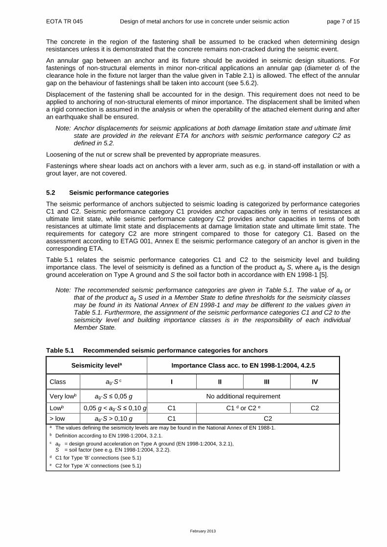
Table 5.1 relates the seismic performance categories C1 and C2 to the seismicity level and building importance class. The level of seismicity is defined as a function of the product ag·S, where ag is the design ground acceleration on Type A ground and S the soil factor both in accordance with EN 1998-1 [5].
Note: The recommended seismic performance categories are given in Table 5.1. The value of ag or that of the product ag·S used in a Member State to define thresholds for the seismicity classes may be found in its National Annex of EN 1998-1 and may be different to the values given in Table 5.1. Furthermore, the assignment of the seismic performance categories C1 and C2 to the seismicity level and building importance classes is in the responsibility of each individual Member State.
Table 5.1 Recommended seismic performance categories for anchors
Seismicity levela Importance Class acc. to EN 1998-1:2004, 4.2.5
Class ag·S c I II III IV
Very lowb ag·S ≤ 0,05 g No additional requirement
Lowb 0,05 g < ag·S ≤ 0,10 g C1 C1 d or C2 e C2
> low ag·S > 0,10 g C1 C2 a The values defining the seismicity levels are may be found in the National Annex of EN 1988-1.
b Definition according to EN 1998-1:2004, 3.2.1.
c ag = design ground acceleration on Type A ground (EN 1998-1:2004, 3.2.1), S = soil factor (see e.g. EN 1998-1:2004, 3.2.2).
d C1 for Type 'B' connections (see 5.1)
e C2 for Type 'A' connections (see 5.1)

EOTA TR 045 Design of metal anchors for use in concrete under seismic action page 8 of 15
February 2013
5.3 Design options
In the design of fastenings one of the following options a1), a2) or b) shall be satisfied (for details see also 5.4):
a) Design without requirements on the ductility of the anchors.
It shall be assumed that anchors are non-dissipative elements and they are not able to dissipate energy by means of ductile hysteretic behaviour and that they do not contribute to the overall ductile behaviour of the structure.
a1) Capacity design: the anchor or group of anchors is designed for the maximum tension and/or shear load that can be transmitted to the fastening based on either the development of a ductile yield mechanism in the fixture or the attached element taking into account strain hardening and material over-strength or the capacity of a non-yielding attached element.
a2) Elastic design: the fastening is designed for the maximum load obtained from the design load combinations that include seismic actions EE,d corresponding to the ultimate limit state (EN 1998-1) assuming an elastic behaviour of the fastening and of the structure. Furthermore uncertainties in
the model to derive seismic actions on the fastening shall be taken into account.
b) Design with requirements on the ductility of the anchors.
The anchor or group of anchors is designed for the design actions including the seismic actions EE,d
corresponding to the ultimate limit state (EN 1998-1). The tension steel capacity of the fastening shall be smaller than the tension capacity governed by concrete related failure modes. Sufficient elongation capacity of the anchors is required. The fastening shall not be accounted for energy dissipation in the global structural analysis or in the analysis of a non-structural element unless proper justification is provided by a non-linear time history (dynamic) analysis (according to EN 1998-1) and the hysteretic behaviour of the anchor is provided by an ETA. This approach is applicable only for the tension component of the load acting on the anchor.
Note: Option b) may not be suitable for the fastening of primary seismic members (EN 1998-1) due to the possible large non-recoverable displacements of the anchor that may be expected. It is recommended to use option b) for the fastening of secondary seismic members. Furthermore, unless shear loads acting on the fastening are resisted by additional means, additional anchors should be provided and designed in accordance with option a1) or a2).
5.4 Design criteria
For the design of anchors according to design option a1), for both Type ‘A’ and Type ‘B’ connections, the fastening is designed for the maximum load that can be transmitted to the fastening based either on the development of a ductile yield mechanism in the attached steel component (see Figure 5.1a)) or in the steel base plate (see Figure 5.1b)) taking into account material over-strength effects, or on the capacity of a non-yielding attached component or structural element (see Figure 5.1c)).
Note: The assumption of a plastic hinge in the fixture (Figure 5.1b)) requires to take into account specific aspects including e.g. the redistribution of loads to the individual anchors of a group, the redistribution of the loads in the structure and the low cycle fatigue behaviour of the fixture.
a) yielding in attached element b) yielding in baseplate c) capacity of attached element
Figure 5.1 Seismic design by protection of the fastening For the design of anchors according to design option a2) the action effects for Type 'A' connections shall be derived according to EN 1998-1 with a behaviour factor q = 1,0. For Type 'B' connections the action effects shall be derived with a behaviour factor qa = 1,0 for the attached element. If action effects are derived in accordance with the simplified approach given in 5.5.4 with qa = 1,0 they shall be multiplied by an amplification factor equal to 1,5. If the action effects are derived from a more precise model this further amplification may be omitted.
EOTA TR 045 Design of metal anchors for use in concrete under seismic action page 9 of 15
February 2013
For the design of anchors according to design option b) the following additional conditions shall be observed:
a) The anchor shall have an ETA that includes a qualification for seismic performance category C2.
b) To ensure steel failure of the fastening condition b1) shall be satisfied for fastenings with one anchor in tension and condition b2) for groups with two and more tensioned anchors. In addition for groups with two and more tensioned mechanical anchors condition b3) applies.
b1) For fastenings with one anchor in tension Equation (5.1) shall be satisfied:
2
seisk,conc,seiss,k, 7,0
RR (5.1)
where
Rk,s,seis = characteristic seismic resistance for steel failure calculated according to Equation (5.8);
Rk,conc,seis = minimum characteristic seismic resistance for all non-steel failure modes (pull-out, concrete cone, combined pull-out and concrete cone, blowout and splitting failure) calculated according to Equation (5.8);
2 = partial safety factor for installation safety given in the relevant ETA.
b2) For anchor groups with two and more tensioned anchors Equation (5.2) shall be satisfied for the anchors loaded in tension:
2
,,,,7,0
gSd
seisconck
hSd
seissk
F
R
F
R (5.2)
where
Rk,conc,seis = minimum characteristic seismic resistance for combined pull-out and concrete cone (only bonded anchors), concrete cone, blowout and splitting failure calculated according to Equation (5.8);
FhSd = design value of resulting load acting on the most stressed anchor of an anchor
group;
FgSd = design value of resulting load acting on the tensioned anchors of an anchor
group.
b3) For a group of mechanical anchors with two and more tensioned anchors the highest loaded anchor shall be verified for pull-out failure according to Equation (5.1) where Rk,conc,seis is the seismic pull-out resistance of one anchor.
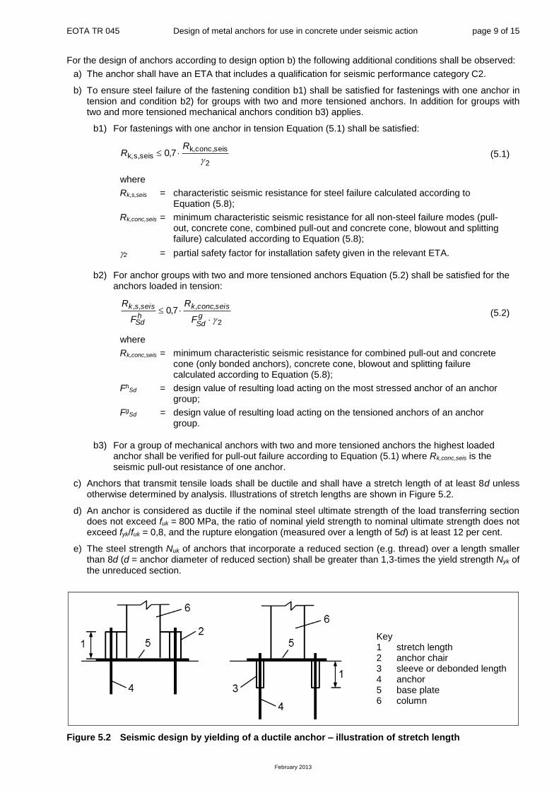
c) Anchors that transmit tensile loads shall be ductile and shall have a stretch length of at least 8d unless otherwise determined by analysis. Illustrations of stretch lengths are shown in Figure 5.2.
d) An anchor is considered as ductile if the nominal steel ultimate strength of the load transferring section does not exceed fuk = 800 MPa, the ratio of nominal yield strength to nominal ultimate strength does not exceed fyk/fuk = 0,8, and the rupture elongation (measured over a length of 5d) is at least 12 per cent.
e) The steel strength Nuk of anchors that incorporate a reduced section (e.g. thread) over a length smaller than 8d (d = anchor diameter of reduced section) shall be greater than 1,3-times the yield strength Nyk of the unreduced section.
Figure 5.2 Seismic design by yielding of a ductile anchor – illustration of stretch length
Key 1 stretch length 2 anchor chair 3 sleeve or debonded length 4 anchor 5 base plate 6 column

EOTA TR 045 Design of metal anchors for use in concrete under seismic action page 10 of 15
February 2013
5.5 Derivation of forces acting on anchors
5.5.1 General
The design value of the effect of seismic actions EE,d acting on the fixture shall be determined according to EN 1998-1 [5] and 5.3 as applicable. Provisions in addition to EN 1998-1 including vertical seismic actions acting on non-structural elements are provided in this Section.
The maximum value of each action effect (tension and shear component of forces for a anchor) shall be considered to act simultaneously if no other more accurate model is used for the estimation of the probable simultaneous value of each action effect.
5.5.2 Addition to EN 1998-1: 2004, 4.3.3.5
For the design of the anchors in Type 'A' connections the vertical component of the seismic action shall be taken into account according to EN 1998-1, Section 4.3.3.5.2 (2) to (4) if the vertical design ground acceleration avg is greater than 2,5 m/s2.
5.5.3 Addition to EN 1998-1:2004, 4.3.5.1
In the design of fastenings for non-structural elements subjected to seismic actions, any beneficial effects of friction due to gravity loads should be ignored.
5.5.4 Additions and alterations to EN 1998-1:2004, 4.3.5.2
The horizontal effects of the seismic action of non-structural elements are determined according to Equation (4.24) of EN 1998-1. However, the behaviour factor qa may be taken from Table 5.2.
Note: Table 5.2 includes information in addition to the values qa given in EN 1998-1, Table 4.4
Table 5.2 Values of qa and Aa for non-structural elements
Type of non-structural element qa Aa
Cantilevering parapets or ornamentations
1,0
3,0
Signs and billboards 3,0
Chimneys, masts and tanks on legs acting as unbraced cantilevers along more than one half of their total height
3,0
Hazardous material storage, hazardous fluid piping 3,0
Exterior and interior walls
2,0
1,5
Partitions and facades 1,5
Chimneys, masts and tanks on legs acting as unbraced cantilevers along less than one half of their total height, or braced or guyed to the structure at or above their centre of mass
1,5
Elevators 1,5
Computer access floors, electrical and communication equipment 3,0
Conveyors 3,0
Anchorage elements for permanent cabinets and book stacks supported by the floor 1,5
Anchorage elements for false (suspended) ceilings and light fixtures 1,5
High pressure piping, fire suppression piping 3,0
Fluid piping for non-hazardous materials 3,0
Computer, communication and storage racks 3,0
EOTA TR 045 Design of metal anchors for use in concrete under seismic action page 11 of 15
February 2013
Equation (4.25) of EN 1998-1 for the seismic coefficient Sa may be rearranged as:
5,01 aa A
H
zSS (5.3)
where
= ratio of the design ground acceleration on type A ground, ag, to the acceleration of gravity g;
S = soil factor;
z = height of the non-structural element above the level of application of the seismic action (foundation or top of a rigid basement);
H = building height measured from the foundation or from the top of a rigid basement;
2
1
aa
)T
T(11
3A
(5.4)
Ta = fundamental vibration period of the non-structural element;
T1 = fundamental vibration period of the building in the relevant direction.
The seismic amplification factor Aa may be calculated according to Equation (5.4) or taken from Table 5.2 if one of the fundamental vibration periods is not known.
Note: When calculating the forces acting on non-structural elements according to Equation (4.25) of EN 1998-1, it can often be difficult to establish with confidence the fundamental vibration period Ta of the non-structural element. Table 5.2 provides a pragmatic approach and may not be conservative in all cases.
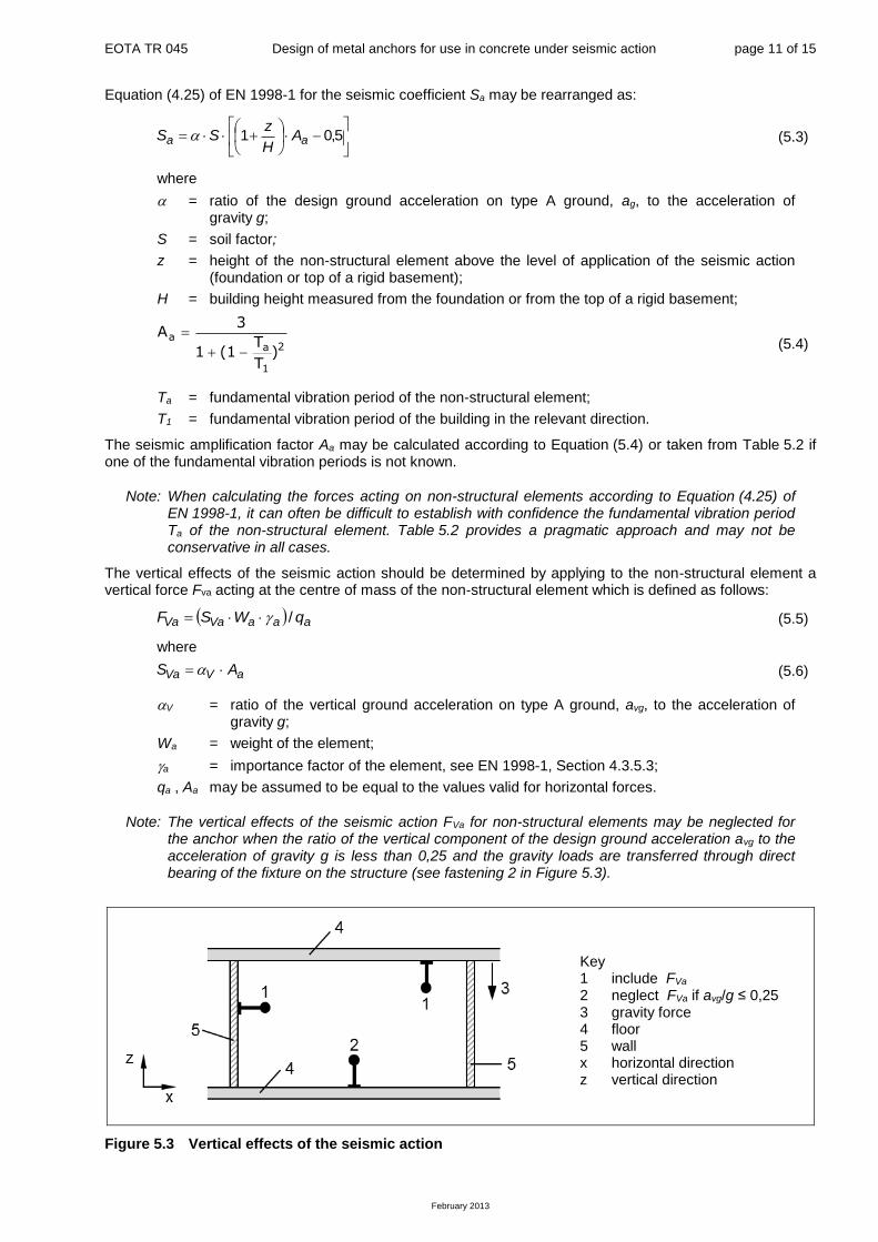
The vertical effects of the seismic action should be determined by applying to the non-structural element a vertical force Fva acting at the centre of mass of the non-structural element which is defined as follows:
aaaVaVa qWSF / (5.5)
where
aVVa AS (5.6)
V = ratio of the vertical ground acceleration on type A ground, avg, to the acceleration of gravity g;
Wa = weight of the element;
a = importance factor of the element, see EN 1998-1, Section 4.3.5.3;
qa , Aa may be assumed to be equal to the values valid for horizontal forces.
Note: The vertical effects of the seismic action FVa for non-structural elements may be neglected for the anchor when the ratio of the vertical component of the design ground acceleration avg to the acceleration of gravity g is less than 0,25 and the gravity loads are transferred through direct bearing of the fixture on the structure (see fastening 2 in Figure 5.3).
Figure 5.3 Vertical effects of the seismic action
Key 1 include FVa 2 neglect FVa if avg/g ≤ 0,25 3 gravity force 4 floor 5 wall x horizontal direction z vertical direction
EOTA TR 045 Design of metal anchors for use in concrete under seismic action page 12 of 15
February 2013
5.5.5 Additions and alterations to EN 1998-1:2004, 4.3.5.4
Upper values for the behaviour factor qa for non-structural elements may be selected from Table 5.2.
5.6 Resistances
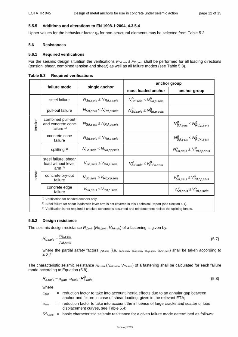
5.6.1 Required verifications
For the seismic design situation the verifications FSd,seis ≤ FRd,seis shall be performed for all loading directions (tension, shear, combined tension and shear) as well as all failure modes (see Table 5.3).
Table 5.3 Required verifications
failure mode single anchor anchor group
most loaded anchor anchor group
tensio
n
steel failure seissRdseisSd NN ,,, hseissRd
hseisSd NN ,,,
pull-out failure seispRdseisSd NN ,,, hseispRd
hseisSd NN ,,,
combined pull-out and concrete cone
failure 1) seispRdseisSd NN ,,,
gseispRd
gseisSd
NN,,,
concrete cone failure
seiscRdseisSd NN ,,, g
seiscRdg
seisSdNN
,,,
splitting 3) seisspRdseisSd NN ,,, g
seisspRdg
seisSdNN
,,,
shear
steel failure, shear load without lever
arm 2) seissRdseisSd VV ,,, h
seissRdh
seisSd VV ,,,
concrete pry-out failure
seiscpRdseisSd VV ,,, g
seiscpRdg
seisSdVV
,,,
concrete edge failure
seiscRdseisSd VV ,,, g
seiscRdg
seisSdVV
,,,
1) Verification for bonded anchors only.
2) Steel failure for shear loads with lever arm is not covered in this Technical Report (see Section 5.1).
3) Verification is not required if cracked concrete is assumed and reinforcement resists the splitting forces.
5.6.2 Design resistance
The seismic design resistance Rd,seis (NRd,seis, VRd,seis) of a fastening is given by:
seisM
seiskseisd
RR
,
,,
(5.7)
where the partial safety factors M,seis (i.e. Ms,seis, Mc,seis, Mp,seis, Msp,seis) shall be taken according to 4.2.2.
The characteristic seismic resistance Rk,seis (NRk,seis, VRk,seis) of a fastening shall be calculated for each failure mode according to Equation (5.8).
0,, seiskseisgapseisk RR (5.8)
where
αgap = reduction factor to take into account inertia effects due to an annular gap between anchor and fixture in case of shear loading; given in the relevant ETA;
αseis = reduction factor to take into account the influence of large cracks and scatter of load displacement curves, see Table 5.4;
R0k,seis = basic characteristic seismic resistance for a given failure mode determined as follows:

EOTA TR 045 Design of metal anchors for use in concrete under seismic action page 13 of 15
February 2013
For steel and pull-out failure under tension load and steel failure under shear load R0
k,seis shall be taken from the relevant ETA (i.e. NRk,s,seis, NRk,p,seis, VRk,s,seis).
For combined pull-out and concrete cone failure in case of bonded anchors R0k,seis
shall be determined as given in EOTA TR 029 (i.e. NRk,p), however, based on the
characteristic bond resistance under seismic loading (Rk,seis) given in the relevant ETA.
For all other failure modes R0k,seis shall be determined as for the design situation for
static loading according to ETAG 001, Annex C or EOTA TR 029 (i.e. NRk,c, NRk,sp, VRk,c, VRk,cp).
Note: The forces on the anchors are amplified in presence an annular gap under shear loading due to a hammer effect on the anchor. For reasons of simplicity this effect is considered only in the resistance of the fastening. In absence of information in the ETA the following values αgap may be used. These values are based on a limited number of tests.
αgap = 1,0 in case of no hole clearance between anchor and fixture;
= 0,5 in case of connections with hole clearance according to Table 2.1.
Table 5.4 Reduction factor seis
Loading Failure mode Single
anchor 1)
Anchor
group
tensio
n
Steel failure 1,0 1,0
Pull-out failure 1,0 0,85
Combined pull-out and concrete failure 1,0 0,85
Concrete cone failure
undercut anchors with the same behaviour as cast-in headed fasteners 2)
all other anchors
1,00 0,85
0,85 0,75
Splitting failure 1,0 0,85
shear
Steel failure 1,0 0,85
Concrete edge failure 1,0 0,85
Concrete pry-out failure
undercut anchors with the same behaviour as cast-in headed fasteners 2)
all other anchors
1,0 0,85
0,85 0,75
1) In case of tension loading single anchor also addresses situations where only 1 anchor in a group of anchors is subjected to tension.
2) Undercut anchors with the same concrete cone capacity in cracked concrete as cast-in headed fasteners, i.e. at least N0
Rk,c = 8.0·(fck,cube)0,5·(hef)1,5; given in the relevant ETA.
5.6.3 Interaction – resistance to combined tension and shear loads
The interaction between tension and shear forces shall be verified according to Equation (5.9).
1,,
seisRd
Sd
seisRd
Sd
V
V
N
N (5.9)
with
NSd/NRd,seis ≤ 1 and VSd/VRd,seis ≤ 1
In Equation (5.9) the largest ratios NSd/NRd,seis and VSd/VRd,seis for the different failure modes shall be inserted, where NSd and VSd are the design actions on the anchors including seismic effects.
5.7 Displacements
The anchor displacement under tensile and shear load at damage limitation state (DLS) shall be limited to a
value N,req(DLS) and V,req(DLS) to meet requirements regarding e.g. functionality and assumed support conditions. These values shall be selected based on the requirements of the specific application. When assuming a rigid support in the analysis the designer shall establish the limiting displacement compatible to the requirement for the structural behaviour.

EOTA TR 045 Design of metal anchors for use in concrete under seismic action page 14 of 15
February 2013
Note: In a number of cases, the acceptable displacement associated to a rigid support condition is considered to be in the range of 3 mm.
If deformations (displacements or rotations) are relevant for the design of the connection (such as, for example, on secondary seismic members or façade elements) it shall be demonstrated that these deformations can be accommodated by the anchors.
The rotation of a connection p (Figure 5.4) is defined by Equation (5.10)
p = N,seis / smax (5.10)
where
N,seis = displacement of the anchor under seismic loading; smax = distance between the outermost row of anchors and the opposite edge of the baseplate.
Figure 5.4 Rotations and anchor displacements
If the anchor displacements N,seis(DLS) under tension loading and/or V,seis(DLS) under shear loading provided in the relevant ETA (for anchors qualified for seismic performance category C2) are higher than the
corresponding required values N,req(DLS) and/or V,req(DLS), the design resistance may be reduced according to Equations (5.11) and (5.12) to meet the required displacement limits.
)(,
)(,,,,
DLSseisN
DLSreqNseisRdreducedseisRd NN
(5.11)
)(,
)(,,,,
DLSseisV
DLSreqVseisRdreducedseisRd VV
(5.12)
If fastenings and attached elements shall be operational after an earthquake the relevant displacements have to be taken into account.
6 Additional proofs for ensuring the characteristic resistance of concrete member The proof of the local transmission of the anchor loads into the concrete member is delivered by using the design methods described in this document.
The transmission of the anchor loads to the supports of the concrete member shall be shown as given in Section 7 of ETAG 001, Annex C and EOTA TR 029 for static loading.
7 References [1] CEN/TS 1992-4 series, Design of fastenings for use in concrete, European Committee for
Standardization (CEN), Brussels, Belgium, 2009.
[2] EN 1990: Eurocode – Basis of structural design, European Committee for Standardization (CEN), Brussels, Belgium.
[3] EN 1992-1-1:2004, Eurocode 2: Design of concrete structures – Part 1-1: General rules and rules for buildings, European Committee for Standardization (CEN), Brussels, Belgium, 2004.
Key 1 sleeve or debonding length 2 anchor 3 baseplate (anchor plate) 4 element

EOTA TR 045 Design of metal anchors for use in concrete under seismic action page 15 of 15
February 2013
[4] EN 1992-4, Design of Fastenings for Use in Concrete, European Committee for Standardization (CEN), Brussels, Belgium (in preparation, not yet published).
[5] EN 1998-1:2004, Eurocode 8: Design of structures for earthquake resistance – Part 1: General rules, seismic actions and rules for buildings, European Committee for Standardization (CEN), Brussels, Belgium, 2004.
[6] EN 206-1, Concrete – Part 1: Specification, performance, production and conformity, European Committee for Standardization (CEN), Brussels, Belgium.
[7] ETAG 001, Guideline for European Technical Approval of Metal Anchors for Use in Concrete, European Organisation for Technical Approvals (EOTA), Brussels, Belgium.
[8] TR 018, Assessment of torque-controlled bonded anchors, European Organisation for Technical Approvals (EOTA), Brussels, Belgium, 2003.
[9] TR 029, Design of Bonded Anchors, European Organisation for Technical Approvals (EOTA), Brussels, Belgium, 2010.


![Design of Metal Anchors For Use In Concrete Under Seismic ... · concrete using approved anchors which fulfil the requirements of ETAG 001 [7] (including EOTA TR 018 [8]). Anchors](https://img.pdfslide.net/doc/110x75/5c69148109d3f25c6a8c8074/design-of-metal-anchors-for-use-in-concrete-under-seismic-concrete-using.jpg)