Embed Size (px)
Citation preview
1729
Design of monocular head-mounted displays,with a case study on fire-fightingJ Wilson∗ and P WrightDepartment of Mechanical Engineering, UC Berkeley, Center for Information Technology Research in the Interest ofSociety (CITRIS), Berkeley, California, USA
The manuscript was received on 27 April 2007 and was accepted after revision for publication on 14 August 2007.
DOI: 10.1243/09544062JMES721
Abstract: The paper presents a design methodology and a case study for monocular head-mounted displays (HMDs), wherein a user can simultaneously and easily see the physical worldby looking through and/or around the display. The design approach is user-focused because ofthe complexity of the human visual system, and because HMDs are very task, user, and contextspecific. A literature review of factors related to HMD design is given. This includes considera-tions for basic optical design, the human visual system, and head and neck biomechanics. GeneralHMD design guidelines are given based on these considerations. For the specific case study onfire-fighting, it is recommended that the HMD be mounted at 15◦ to 45◦ below the Frankfurtplane, with a 15◦ to 40◦ field of view. A resolution of 20–60 px/deg should be focused at 1 m orfarther. The neck joint torque due to the HMD should not exceed about 1 Nm. This equates to atypical maximum weight of 0.5 to 1 kg depending on the mounting location.
Keywords: head-mounted display design, emergency first response, fire-fighting
1 INTRODUCTION
1.1 Literature review: head-mounted displays
Head-mounted displays (HMDs) allow a user toview information on a small screen that is typicallymounted on a facepiece, helmet, hat, or special eye-glasses (Fig. 1). A convenient and hands free formatis key to the user acceptance of the device. HMDsare classified into three ocular types: monocular – forsingle eye viewing, biocular – for both eyes, and binoc-ular – for stereovision by presenting a slightly differentimage perspective to each eye [1]. HMDs were firstdeveloped in the 1960s by university researchers [2–4].More recently, inexpensive flat panel microdisplayshave enabled many applications for military pilots andsoldiers, virtual reality, entertainment, wearable com-puting, advanced surgery, auto mechanics, and firstresponders.
∗Corresponding author: Department of Mechanical Engineer-
ing, UC Berkeley, Center for Information Technology Research in
the Interest of Society (CITRIS), Berkeley, CA 94720, USA. email:
1.2 A ‘Framework’ for the methodology andorganization of the current paper
Ishikawa (1963) and other researchers introducedthe ‘cause and effect’ or ‘fishbone’ type diagram foranalysing any design or manufacturing task that willinvolve many interrelating parameters [5]. Figure 2shows such a diagram that the authors have pre-pared for the Case Study on an HMD for firefightingdescribed later. Figure 3 represents the top half ofFig. 2, but with component-based design requirementtopics rather than human-based. For example, ‘Visualacuity’ of the eye in Fig. 2 is replaced with ‘Resolution’of the display screen in Fig. 3. The design methodologyused is human-based in order to emphasize properHMD functionality in terms of the capabilities of theuser. This is opposed to focusing on component func-tionality, which may create unnecessary capabilitiesand functionalities. This in turn increases cost andcomplexity in a product that must be easy to use andcost-effective. These diagrams are presented here atthe beginning of the paper (rather than in section 5) toprovide a convenient framework for the reader, priorto describing many of the specific details on optics andergonomics in the following four main sections:
JMES721 © IMechE 2007 Proc. IMechE Vol. 221 Part C: J. Mechanical Engineering Science

1730 J Wilson and P Wright
Fig. 1 Prototype fire-fighter monocular HMD infacemask
(a) section 2: basic HMD optical design;(b) section 3: human visual considerations;(c) section 4: head and neck biomechanics;(d) section 5: generic design guidelines.
The authors have drawn on the HMD literature togive generic human-centred functional requirements(FRs) in sections two through four, and design guide-lines for HMDs in section five. Section 6 presents thespecific design parameters (DPs) for the HMD recom-mended for fire-fighting ([6, 7], for a review of FRsand DPs). Table 1 provides a summary of some of thenomenclature used throughout.
2 LITERATURE REVIEW OF BASIC HMDOPTICAL DESIGN
2.1 Overview of optical layout
Any HMD needs an optical train from the microdisplayto the eye to magnify the information to a viewablesize. A generic example is shown in Fig. 4, wherea simple magnifier objective lens, a mirror, and abeamsplitter are used to create a see-through design.When using a simple magnifier, the object, being themicrodisplay, is placed at or within the focal length ofthe lens to obtain a virtual upright image.
2.2 ‘Look-around’ versus ‘See-through’
An early design consideration to make is whether theHMD will be an occluded look-around design or asee-through design. A look-around system is a train ofoptical elements through which one sees the displayscreen, usually focused to appear at or near infinity.Everything behind the screen is occluded, like lookingat a TV. These HMDs are small enough to look to oneside of them to see the real world.
Alternatively, the optics may be designed to createa see-through system that reflects light into the pupilvia a beamsplitter. The user of such a system would seea virtual image ‘floating’ in space. The imagery usu-ally adds useful information to the real environment
Fig. 2 Fishbone overview diagram of the case study on the HMD for fire-fighting described laterin section 5 of the paper
Proc. IMechE Vol. 221 Part C: J. Mechanical Engineering Science JMES721 © IMechE 2007

Design of monocular head-mounted displays 1731
Fig. 3 Top half of Ishikawa diagram, showing component based metrics for an HMD
Table 1 Some human factors nomenclature and definitions for HMDs
Instantaneous field of view Horizontal and vertical angular visual fieldFoveal resolution Central retinal area of highest visual precisionLuminance and contrast Sensitivity limits to visionCFF Minimum image update rate to avoid display flickerInterpupillary distance Horizontal distance between the eye pupilsNear point Closest location from eye an object can be held in focusRPV Location at which eyes converge at rest without a stimulusOcular motion effects How eye position affects vergence and accommodationVisual problems Unwanted psychophysical reactions to HMDOcular anthropometrics Measurements of eye locations on facesHead and neck biomechanics Effects of added head weight on neck fatigue and damage
Fig. 4 Example see-through HMD optical layout
by overlaying data onto immediate objects in thatscene. Thus, the see-through design may be referredto as an augmented reality display. An automotivemechanic, for example, would likely see a part dia-gram and installation instructions superimposed onthe actual part [8].
2.3 Pupil versus non-pupil forming optics
The designer must also consider whether the opticalsystem will be pupil forming, as with a compoundmicroscope, or a non-pupil forming simple magnifier,as in a magnifying glass. A pupil forming system formsthe image at a two-dimensional circular area in space,while a non-pupil system forms a conical area allowingmore forward-back eye movement without losing the
Fig. 5 Diagram of a basic compound microscope show-ing chief and marginal rays
image. Too much movement back will cause the imageto vignette, where the periphery blurs and disappears.The basic compound microscope layout is shown inFig. 5.
2.4 Optical design parameters
Table 2 gives metrics commonly used to design amonocular HMD and analyse its optical performance.
The exit pupil determines the screen image locationand the light flux reaching the eye. In a pupil formingoptical system, the exit pupil location is calculatedwith the Gaussian lens formula
1f
= 1di
+ 1do
(1)
JMES721 © IMechE 2007 Proc. IMechE Vol. 221 Part C: J. Mechanical Engineering Science

1732 J Wilson and P Wright
Table 2 Typical monocular HMD metrics
Metrics
Exit pupil location Eye clearanceExit pupil diameter Eye reliefFOV Eyepiece diameterMagnification ResolutionImage focal range Luminance throughput
This formula is used for paraxial light rays entering theparaxial region of a spherical lens. A paraxial ray is onefor which its sine and tangent are very similar, and theparaxial region is that near the optical axis. In the non-pupil example, however, there will be a cone of light inwhich the eye can be positioned to see the image. Thediameter of this cone as a function of the eye distancefrom the eyepiece is given by
Dep = Dlens − LeSf
(2)
where Dlens is the eyepiece diameter, Le is the eye relief,S is the screen diagonal, and f is the focal length. Thisequation is valid when the microdisplay is positionedat the lens focal point.
The eye relief of the eyepiece is the distance from thelast optical element to the cornea of the eye. The eyeclearance is the distance from the last physical objecton the HMD to the cornea of the eye, and is importantfor viewing comfort. It is usually the same, as or slightlyless than, the eye relief.
The apparent screen image size is given by the fieldof view (FOV) of the system
FOV = 2 · arc tan(
S2fe
)(3)
where S is the display screen size (horizontal, vertical,or diagonal) and fe is the focal length of the eyepiece.
Magnification can be found in general the ratio ofthe image height to the object height. For a simplemagnifier, it can be found by the ratio of the angu-lar subtense from the aided eye to the object, viewedthrough the magnifier, to the angular subtense fromthe unaided eye to the object viewed at the normalnear point of 0.25 m [9]. When viewing an HMD, thisis equivalent to the ratio of the FOV to viewing thedisplay screen unaided at 0.25 m.
MP = αa
αu= FOV
arc tan(S/0.25)(4)
Diffraction in a lens causes image points to spread. Thediffractive limit of resolution of the eyepiece is found
using
(�l)min = 1.22feλ
D(5)
where �l is the centre to centre separation of twoimages (e.g. two dots), fe is the focal length of the eye-piece, λ is the wavelength (550 nm for white light), andD is the aperture diameter of the optical system [9].This is rarely the limiting imaging factor in an HMD. Itis usually the microdisplay pixel resolution.
Image distortion is a frequent problem and is com-monly due to spherical lens aberrations. Sphericallenses are less expensive and more commonly avail-able than parabolic or other aspheric lenses, thus theyare more commonly used.When designing with spher-ical lenses, however, if the paraxial approximation isnot followed, then aberrations become quite problem-atic. Six common types of aberrations are: spherical,coma, astigmatism, distortion, field curvature, andchromatic. Aspheric and achromatic lenses are oftenused to correct these problems.
2.5 Display selection
Flat panel microdisplays are the most commonlyused image source for an HMD. They are producedusing MEMS technology, and one must use magnify-ing optics in order to read what is being displayed.This technology was pushed by a DARPA HMD pro-gram in the 1990s as a replacement for the heavierand bulkier cathode ray tube [10]. Multiple types ofthese microdisplays are now being mass-produced. Aselection of these is compared in Table 3, with advan-tages and disadvantages relevant to HMD design. Alsoincluded is a retinal scanning display, which is not aflat panel design but is used in a commercial HMD.
Display image quality is often described by reso-lution, contrast, and luminance. The resolution of adisplay can be given by the pixel count, for examplevideo graphics array (VGA), being 640 × 480 pixels, orby the angular subtense of a single pixel. The latteris calculated by dividing the FOV seen by the HMDwearer by the number of pixels (N ) along that samedimension
Resolution = FOVN
(6)
3 LITERATURE REVIEW OF HUMANVISUAL CONSIDERATIONS
3.1 Overview of human eye parameters
When designing an HMD, it is important to understandthe abilities and limitations of the average humaneye. This enables the designer to tailor the optical
Proc. IMechE Vol. 221 Part C: J. Mechanical Engineering Science JMES721 © IMechE 2007
Design of monocular head-mounted displays 1733
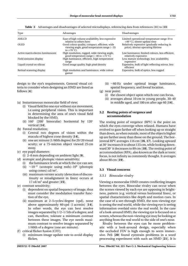
Table 3 Advantages and disadvantages of selected microdisplays, referencing data from references [11] to [13]
Type Advantages Disadvantages
AMLCD Ease of high volume availability, less expensiverelative to others here
Limited operational temperature range (0 to+60 ◦C), slower update time
OLED Good colour quality, compact, efficient, wideviewing angle, good temperature range (−35to +70 ◦C)
Relatively expensive (gradually reducing inprice), shorter operating lifetime
Active matrix electro-luminescent High resolution, rugged, wide viewing angle,good temperature range (−40 to +75 ◦C)
Low luminance, limited colours, less efficient,relatively expensive
Field emission display High luminance, efficient, high temperaturerange
Less mature technology, less availability,expensive
Liquid crystal on silicon Good image quality, high pixel density Expensive, bulk of light reflecting mirror, lessefficient
Retinal scanning display High resolution and luminance, wide colourgamut
Expensive, bulk of optics, less rugged
design to the eye’s requirements. General visual cri-teria to consider when designing an HMD are listed asfollows [4]:
(a) Instantaneous monocular field of view;(i) Visual field for one eye without eye movement,
i.e.using peripheral vision. This is importantin determining the area of one’s visual fieldblocked by the HMD,
(ii) 160◦ (200◦ binocular) horizontal by 120◦
vertical [14].(b) Foveal resolution;
(i) Central two degrees of vision within themacula of highest cone density [14],
(ii) one arc minute (1/60th degree) for 20/20 visualacuity; or a 75-micron object viewed 25 cmaway.
(c) eye pupil diameter;(i) 2–8 mm depending on ambient light [9].
(d) scotopic and photopic vision sensitivity;(i) the luminance levels at which the eye can see,(ii) ∼10−6 (scotopic using rods)–106 (photopic
using cones) cd/m2,(iii) maximum vernier acuity (detection of discon-
tinuity or misalignment in lines) occurs at17 cd/m2 and greater [15].
(e) contrast sensitivity;(i) dependent on spatial frequency of image, thus
must consider the modulation transfer func-tion of the eye,
(ii) maximum at 2–5 cycles/degree (cpd), noneabove approximately 60 cpd (1 acrmin) [14].In other words, the eye can best resolveimages separated by 1/2–1/5th of a degree, andcan, therefore, tolerate a minimum contrastbetween these images. The eye needs maxi-mum contrast to resolve images separated by1/60th of a degree (one arc minute).
(f) critical flicker fusion (CFF);(i) minimum image update rate to avoid display
flicker,
(ii) ∼60 Hz under optimal image luminance,spatial frequency, and foveal location.
(g) near point;(i) the closest object upon which one can focus,(ii) averages about 10 cm in young people, 30–40
in middle aged, and 100 cm after age 60 [14].
3.2 Resting points of vergence andaccommodation
The resting point of vergence (RPV) is the point onwhich the eyes converge when relaxed. Humans haveevolved to gaze farther off when looking up or straightthan down, as when outside, most of the objects higherup are farther away than those on the ground. The hor-izontal RPV averages 116 cm [16, 17]. Looking upwardat 30◦ increases it to about 135 cm, while looking down-ward 30◦ it decreases to 89 cm [18]. The resting point ofaccommodation (RPA), also known as the dark or tonicfocus, is not infinity as commonly thought. It averagesabout 80 cm [19].
3.3 Visual concerns
3.3.1 Binocular rivalry
Viewing a monocular HMD creates conflicting imagesbetween the eyes. Binocular rivalry can occur whenthe scenes viewed by each eye are opposing in bright-ness, pattern (e.g. vertical versus horizontal lines), orspatial characteristics like depth and motion cues. Inthe case of a see-through HMD, the non-viewing eyeis seeing the real world, while the viewing eye is seeinginformation overlaid onto the real world. In the caseof a look-around HMD, the viewing eye is focused on ascreen, whereas the non-viewing eye may be looking atanything from the real world to the side of one’s nose.
Rivalry between the eyes can be more problem-atic with a look-around design, especially whenthe occluded FOV is high enough to seem immer-sive. Peli [20] found eyestrain problems in a wordprocessing experiment with such an HMD [21]. It is
JMES721 © IMechE 2007 Proc. IMechE Vol. 221 Part C: J. Mechanical Engineering Science

1734 J Wilson and P Wright
especially problematic over long periods (hours) offrequent use.
See-through designs, however, can also causeproblems. Apache helicopter pilots use the inte-grated helmet and display sighting system (IHADSS)see-through monocular HMD on multi-hour nightmissions. One eye views a dark cockpit and nightscene, and the other a bright image overlaid onto thisscene. They report rivalry symptoms, and after-effectsincluding visual fatigue and headaches [22].
3.3.2 Other problems
Other documented concerns include visual nauseaand the Pulfrich phenomenon. Visual nausea, orcybersickness, occurs due to latency in visual ver-sus vestibular motion cues. This is more common inimmersive virtual reality displays with head tracking.The display imagery will lag behind one’s sense ofmotion, causing dizziness and nausea. The Pulfrichphenomenon occurs under ocular luminosity differ-ences. An image delay to the darker adapted eye resultsin depth illusions for laterally moving objects [4]. Fur-ther visual problems can occur in accommodating tothe HMD screen. If the screen is not focused at thesame distance as objects viewed in the real world,the user will have to re-accommodate when switchingbetween the different depth cues.
Instrument myopia, common with microscopes, isreturn of the accommodative state of the eye to anintermediate distance when viewing an optical instru-ment such as an HMD [23]. Recall that the RPA is at lessthan a metre. The instrument may be focused at infin-ity, but the eye eventually involuntarily accommodatescloser, resulting in a blurry image. This creates visualdiscomfort and can result in headaches or eyestrain.
Similar to instrument myopia is the ‘near response’that can occur when an instrument like a microscopeor HMD is brought near the eye [24, 25]. The brainprocesses stimuli to determine how far away an objectis.There is conflicting information from the knowledgethat the instrument is very close to the eye, and theimage is focused far away. A response may occur inwhich the eyes converge and accommodate inwardmore than needed.
4 HEAD AND NECK BIOMECHANICALCONSIDERATIONS
This section discusses how the location and weightof the HMD interact with the user’s head and neck.Parameters of these body parts must be taken intoaccount in the design in order to achieve user comfort.These include facial anthropometrical data, head iner-tial parameters, static neck strength, and biodynamicdata. Referring to the Ishikawa diagram in Fig. 2, this
section focuses on many of the functional requirementtopics in the upper left ‘Human factors’ segment. Theliterature will be referenced for head and neck data.This data will be used for an analysis of the relation-ship between HMD mass and the mounting locationrelative the head in order to avoid neck fatigue.
4.1 Literature review of head and neckbiomechanics
4.1.1 Facial anthropometrics
The HMD must have a range of motion such that itcan be adjusted to any given user’s face. Facial anthro-pometrics for this discussion refers to the location ofthe viewing eye relative to other features of the face.The most important measures are the inter-pupillarydistance (IPD) and the vertical position of the eye. TheIPD is the distance between the centres of each pupil,and is more important in designing biocular or binoc-ular than monocular HMDs for proper alignment toboth eyes. IPD averages 63 mm and varies from 53–73 mm [26]. The vertical position of the pupil is oftenmeasured with respect to the Frankfurt plane. TheFrankfurt plane passes horizontally through the tra-gion flap forward of the ear orifices and the orbitalnotch at the base of the eye sockets. This plane rotateswith the head (Fig. 6).
4.1.2 Head and neck strength
An HMD can cause injury to the neck if it is too heavy.The allowable weight depends on the location relativeto the head, the physical characteristics of the user,and on the intended use. Many HMDs are used undernear static conditions with very low magnitude head
Fig. 6 Anatomical coordinate system of head (adaptedfrom [4])
Proc. IMechE Vol. 221 Part C: J. Mechanical Engineering Science JMES721 © IMechE 2007
Design of monocular head-mounted displays 1735
accelerations, such as standing and walking. Underthese conditions, a heavier system may be allowableand user discomfort is most likely to be realized asneck fatigue. Military pilots, however, will encounterhigh accelerations creating dangerous g-forces. Toomuch weight on the head will cause neck damageunder these conditions. For this discussion, the focuswill be on static or near static conditions.
In static conditions, human muscles can hold anisometric contraction of about 15 per cent of themuscle’s maximum strength for an indefinite periodof time with minimal fatigue [27]. The anatomicalmotion of interest for an HMD is extension, or tilt-ing the head back, for which the dorsal neck musclesposterior to the spine are responsible. Studies haveshown maximum voluntary moments of 25.9 Nm dur-ing extension, and average dorsal cervical musclestrength of 131.8 N [28, 29]. Using the 15 per cent find-ing, the maximum allowable dorsal muscle force toavoid fatigue will be approximated as 20 N.
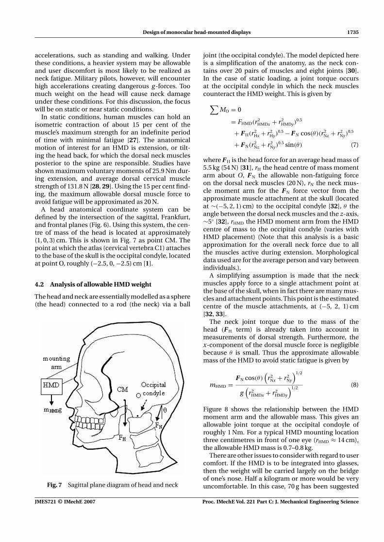
A head anatomical coordinate system can bedefined by the intersection of the sagittal, Frankfurt,and frontal planes (Fig. 6). Using this system, the cen-tre of mass of the head is located at approximately(1, 0, 3) cm. This is shown in Fig. 7 as point CM. Thepoint at which the atlas (cervical vertebra C1) attachesto the base of the skull is the occipital condyle, locatedat point O, roughly (−2.5, 0, −2.5) cm [1].
4.2 Analysis of allowable HMD weight
The head and neck are essentially modelled as a sphere(the head) connected to a rod (the neck) via a ball
Fig. 7 Sagittal plane diagram of head and neck
joint (the occipital condyle). The model depicted hereis a simplification of the anatomy, as the neck con-tains over 20 pairs of muscles and eight joints [30].In the case of static loading, a joint torque occursat the occipital condyle in which the neck musclescounteract the HMD weight. This is given by
∑MO = 0
= FHMD(r2HMDx + r2
HMDy)0.5
+ F H(r2Hx + r2
Hy)0.5 − F N cos(θ)(r2
Nz + r2Ny)
0.5
+ F N(r2Nz + r2
Ny)0.5 sin(θ) (7)
where F H is the head force for an average head mass of5.5 kg (54 N) [31], rH the head centre of mass momentarm about O, F N the allowable non-fatiguing forceon the dorsal neck muscles (20 N), rN the neck mus-cle moment arm for the F N force vector from theapproximate muscle attachment at the skull (locatedat ∼(−5, 2, 1) cm) to the occipital condyle [32], θ theangle between the dorsal neck muscles and the z-axis,∼5◦ [32], rHMD the HMD moment arm from the HMDcentre of mass to the occipital condyle (varies withHMD placement) (Note that this analysis is a basicapproximation for the overall neck force due to allthe muscles active during extension. Morphologicaldata used are for the average person and vary betweenindividuals.).
A simplifying assumption is made that the neckmuscles apply force to a single attachment point atthe base of the skull, when in fact there are many mus-cles and attachment points. This point is the estimatedcentre of the muscle attachments, at (−5, 2, 1) cm[32, 33].
The neck joint torque due to the mass of thehead (F H term) is already taken into account inmeasurements of dorsal strength. Furthermore, thex-component of the dorsal muscle force is negligiblebecause θ is small. Thus the approximate allowablemass of the HMD to avoid static fatigue is given by
mHMD =F N cos(θ)
(r2
Nx + r2Ny
)1/2
g(
r2HMDx + r2
HMDy
)1/2 (8)
Figure 8 shows the relationship between the HMDmoment arm and the allowable mass. This gives anallowable joint torque at the occipital condoyle ofroughly 1 Nm. For a typical HMD mounting locationthree centimetres in front of one eye (rHMD ≈ 14 cm),the allowable HMD mass is 0.7–0.8 kg.
There are other issues to consider with regard to usercomfort. If the HMD is to be integrated into glasses,then the weight will be carried largely on the bridgeof one’s nose. Half a kilogram or more would be veryuncomfortable. In this case, 70 g has been suggested
JMES721 © IMechE 2007 Proc. IMechE Vol. 221 Part C: J. Mechanical Engineering Science

1736 J Wilson and P Wright
Fig. 8 Relationship between HMD moment arm andallowable mass
as a reasonable glasses-mounted weight for adequateuser comfort [34].
4.3 Biodynamic considerations
Various studies testing neck forces under dynamicloading have been performed, primarily for mili-tary testing of pilot helmets and HMDs. The testsare done under extreme conditions to mimic emer-gency incidents such as ejection from the cockpit.The high accelerations present in these situations cre-ate large forces on the neck. Results indicate that thehead-mounted weight should be about 1.8 kg or less,mounted as close to the head as possible to mini-mize joint torque due to leveraging of weight on theneck [27].
5 GENERIC DESIGN GUIDELINES
To improve user performance, the HMD design shouldbe focused toward ergonomic requirements, taskrequirements, and user needs. Task requirements anduser needs are specific to the application. Ergonomicrequirements, however, are more generic and designguidelines will be given in terms of these requirements.The first part of this section gives a literature reviewof typical optical specifications for any HMD design,shown in Table 4. The second part elaborates upon and
Table 4 Typical optical specifications for anHMD from Fischer [35]
Parameter Typical specification
FOV 30◦Focal range 3 m if fixedExit pupil diameter �7 mmEye clearance �25 mm (for glasses use)Resolution 20 px/deg for video viewingOptical distortion <5%
supplements these specifications to focus on genericguidelines for monocular HMDs.
5.1 Literature review of general HMD opticaldesign parameters
Table 4 gives important design parameters and theirtypical specifications for an HMD. Some characteris-tics, such as FOV, will vary greatly depending on thetype of HMD and its intended task. Others, such as exitpupil diameter and distortion, should be consistentacross all designs.
5.1.1 Focal range
Ideally, the HMD image distance should be adjustableover a wide range, from 1 m to infinity, to allow for dif-ferent users and tasks. At the least, it should appear ator farther than the RPV for maximum viewing comfort.If elderly people are to be users, their near point maybe upwards of 100 cm, and the image must be at leastthis distant. Depending on the application, however,corrective lenses may be worn to give normal visionwhen viewing an HMD.
A common misconception is that the image is bestfocused at infinity. This, however, may not be opti-mal based on tonic accommodation data and usertask requirements. As previously noted, given no visualstimulus (e.g. pitch black conditions), the eye nat-urally accommodates to about 80 cm. Furthermore,when using an infinite conjugate instrument, instru-ment myopia can occur. Ankrum [36] found that for adesktop monitor, moving beyond one’s RPV does notproduce additional benefits. It is reasonable to assumethat focusing the image to a distance similar to objectsbeing viewed in the real world is appropriate.
5.1.2 Exit pupil and luminance throughput
According to Fischer, the diameter of the human pupilranges in size from roughly 2.5–7 mm. An HMD exitpupil diameter of at least 7 mm allows for movementof the eye relative to the HMD in all but the darkestconditions. This will reduce the need for HMD positionadjustments, thereby improving user satisfaction.
The exit pupil diameter determines the light fluxentering the eye. As previously noted, maximumvernier acuity occurs at 17 cd/m2. In good readinglight, luminance from a white piece of paper is aboutan order of magnitude higher [37]. Many microdis-plays have a luminance of about 100 cd/m2. Note thata typical simple optical system with a few elementsreduces the display luminance by about 10 per cent,and a beamsplitter will reduce throughput by its trans-mission ratio, which is generally about 50 per cent.
Proc. IMechE Vol. 221 Part C: J. Mechanical Engineering Science JMES721 © IMechE 2007

Design of monocular head-mounted displays 1737
5.1.3 Eye clearance
Eye clearance is an important parameter in designingfor viewing comfort. Too close and the HMD may beintrusive, especially with a look-around HMD. As eyeclearance decreases, the apparent level of immersionand brightness will increase. The FOV of the physi-cal HMD will also increase, which decreases the visualfield of the real world. This will increase the likelihoodof visual problems, such as binocular rivalry.
See-through HMDs are less intrusive by design, andless clearance may be acceptable. Intrusiveness alsodepends on the mounting location. If glasses are tobe used, Fischer recommends a clearance of at least25 mm for adequate comfort.
5.1.4 Resolution and frame rate
To match the one arc minute resolution of nor-mal vision, the screen must have at least 60 px/deg.Such high resolution, however, may not be necessarydepending on the detail of information that needsto be shown. One-third of this amount is adequatefor-video viewing [35].
Frame rate of the display must exceed the eye’sCFF for the appearance of smooth imagery. Giventhat the CFF of the eye can be over 60 Hz, the framerate should be 60 Hz or more for fast moving images.Davis [14] recommends a display update rate (fre-quency at which the image is updated) of 30 Hz forslow moving objects.
5.2 Optical design considerations for monocularHMDs
5.2.1 Field of view
A tradeoff comes into play in designing an HMDbetween how much information one would like tosee on the screen, and how much of one’s visual fieldis blocked when wearing the HMD. This is shown inFig. 9 for horizontal vision. The data points occur at
Fig. 9 Tradeoff between horizontal display size andvisual field
three standard microdisplay sizes of 320, 640, and800 pixels. FOV is calculated for a focal length of21.4 mm. Normally this is a linear relationship, how-ever the 800 × 600 display data are from an eMaginorganic light emitting diode (OLED), while the oth-ers are Kopin LCDs, thus the pixel density is notconstant.
The allowable amount of visual field that can beblocked will depend on the task at hand and userpreferences. The designer must weigh the costs andbenefits of having more information available or easierto see versus the extra distraction caused by block-ing more of a person’s 160◦ × 120◦ monocular visualfield.
For an immersive application such as virtual real-ity, the designer would strive for a wide FOV HMD.Monocular HMDs, however, are generally used in non-immersive applications. Examples include those fromLiteye, Eyetop, and Microoptical, which have a 20–40◦
FOV [38]. This typically allows one to clearly see a VGAor super video graphics array (SVGA) sized screen.Proper placement in the visual field or the ability toswing the HMD out of the way minimizes distraction.
5.2.2 Pupil versus non-pupil forming
The simple magnifier can be as simple as a singleconvex lens. Many simple magnifiers, however, haveadditional optical elements to cancel aberrations, orimage errors. Advantages of the simple magnifier overthe microscope design include less cost, a shorteroptical path length creating smaller size, less weight,and better light transmission due to fewer opticalelements. The longer optical path length of the com-pound microscope may be an advantage, however, ifthe designer folds the optical path around the wearer’shead. In this way, the optics can be closer to thehead, making the centre of mass of the HMD closerto the head. This in turn reduces neck fatigue. Finally,the compound microscope has the ability to magnifythe object more than a simple magnifier, as its mag-nification is the product of its objective and eyepiecemagnifications.
5.2.3 ‘Look-around’ versus ‘See-through’
The optical system may be see-through or look-around. Each has its advantages and disadvantagesin different types of tasks. The see-through has theadvantage of being able to more quickly and seam-lessly glance between displayed information and thesurrounding environment, because the information isoverlaid onto the real world. The look-around requiressome time for the eye to adjust to the new setting.Both designs may require accommodation in the tran-sition. See-through disadvantages include the extra
JMES721 © IMechE 2007 Proc. IMechE Vol. 221 Part C: J. Mechanical Engineering Science

1738 J Wilson and P Wright
bulk, weight, and cost of the optics, viewing dif-ficulty against bright backgrounds, and typically a40–60 per cent loss in luminance throughput due toreflection and transmission at the beamsplitter. Thusa see-through will require more power for equivalentluminance.
The see-through is well suited to tasks that requireone to directly relate objects in the real world toinformation on the display. These are augmented real-ity applications. Apache pilots, for example, use theIHADSS see-through HMDs so that they can targetobjects while flying [39].The look-around is well suitedto applications requiring a large FOV fully immersivedisplay that purposefully excludes the real environ-ment. It is also suited to a small peripheral non-distracting display that minimizes immersion anddistraction. The information presented may be textor non-local information that is not usefully overlaidonto one’s immediate environment, and that wouldotherwise be difficult to discern against a bright orhighly contrasting background.
5.3 Location in the visual field
The monocular HMD must be mounted such that theentire screen is within the FOV of one of the eyes. Theright eye is commonly chosen because about 70 percent of people are right-eye dominant [40, 41]. Somepeople, however, have poorer vision in one eye, thus itis beneficial to design for use with either eye.
There are arguments for mounting an HMD low inone’s visual field. Ripple [42] found it is less fatiguingto converge one’s eyes on a near object when look-ing down. The extraocular muscles of the eye controlup–down movement, and the medial recti musclescontrol ocular vergence. When the extraoculars rotatethe eye upward, they apply a divergent force thatmust be overcome by the medial rectis. Thus con-verging while looking downward is more comfortable[43–45]. This can be seen when a person naturallylooks down to read, and is one reason why Burgess–Limerick et al. [46] suggest that a desktop monitorshould be at least 15◦ below one’s normal horizontalline of sight.
An HMD should not obstruct one’s vision whilewalking. Many obstacles are seen in peripheral vision,but a person may glance down to see an obstacle. If,for example, a six-foot person is looking at an object10 ft away on the ground while walking, the angleof ocular vergence is about 30◦ downward. This iscommonly accompanied by tilting the head down,however, which can reduce the required ocular ver-gence to less than 10◦. Thus, an occluded HMD shouldbe small enough that the user can easily see aroundit, and mounted at least 15◦ below the horizontal lineof sight for obstacle avoidance. A maximum of 45◦
is recommended to avoid eyestrain due to excessivedownward ocular motion.
5.4 Visual concerns
Many of the visual concerns explained in section 3.3are more problematic in an immersive HMD. A largerFOV and an occluded design increases immersion intothe virtual world of the computer. To reduce visualproblems, the design should maximize the feelingof being in the real world, and minimize dizzyingvideo imagery such as screen rotations and disorient-ing object movements. Other helpful features includea small FOV design mounted below one’s horizontalline of sight, see-through optics, minimal informationlatency (especially regarding movement), a light meterto automate brightness, and a graphical user interface(GUI) that is clear and non-distracting.
6 CASE STUDY ON FIRE-FIGHTING
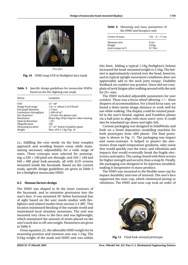
The Fire Information and Rescue Equipment Projectis researching ways of giving all critical informationand decision support tools to all firefighters involvedat an incident (Fires account for more deaths in theUnited States than all natural disasters combined. Anaverage of 4000 people die per year with billions lost inproperty damage. The World Trade Centre attack itselfcost New York City $33.4 billion in property damage(USFA, 2003), and over 2800 lives, 350 of whom werefirefighters (McKinsey, 2002). The McKinsey Reportfollowing 9/11 is just one case study arguing for moreeffective rescue operations.). The main goals are toimprove efficiency and save more lives. One of the keycomponents is a monocular HMD (Fig. 10). This casestudy discusses its design as an example of using theabove guidelines, and gives more specific HMD designrecommendations for emergency response.
6.1 User needs gathering
Understanding the needs of the user is critical indesigning a device with which humans interface.Over 50 firefighters and three fire chiefs from theChicago and Berkeley Fire Departments were inter-viewed (see [47, 48] for a more complete overviewof the current study). Prototypes were developed inan iterative process, wherein feedback was incorpo-rated into the next rendition, demonstrated and testedagain, and redesigned. The most important needsfound concerned ease of use and maintenance, dura-bility, and minimal distraction, while presenting usefulinformation in an intuitive manner.
Screening and scoring weighted decision matriceswere created based on the user needs data. The result-ing design choices tended toward Occam’s razor [49],
Proc. IMechE Vol. 221 Part C: J. Mechanical Engineering Science JMES721 © IMechE 2007
Design of monocular head-mounted displays 1739
Fig. 10 HMD map GUI in firefighter face mask
Table 5 Specific design guidelines for monocular HMDsbased on the fire-fighting case study
Metric Guideline
FOV 15◦–40◦Image focal range 1 m–∞ (about 3 m if fixed)Exit pupil diameter �7 mmLuminance throughput �100 cd/m2
Eye clearance �25 mm (for glasses use)Resolution 60 px/deg; 20 px/deg for video viewingOptical distortion <5%Magnification 10XMounting location 15◦–45◦ below Frankfurt planeWeight Max. of 0.5–1 kg (Fig. 8)
i.e., fulfilling the core needs via the least complexapproach and avoiding feature creep while main-taining necessary adjustability for a wide range ofusers. Three concepts were selected for prototyp-ing: a 320 × 240 pixel see-through, and 320 × 240 and640 × 480 pixel look-arounds, all with LCD screensmounted inside the facemask. Based on the currentstudy, specific design guidelines are given in Table 5for a firefighter monocular HMD.
6.2 Human factors design
The HMD was shaped to fit the inner contours ofthe facemask, and to minimize protrusion into theuser’s face. It was mounted 30◦ below horizontal lineof sight based on the user needs studies with fire-fighters and related studies from section 5.3 [47]. Thislocation minimized blocking of the outside world andmaintained local situation awareness. The unit wasmounted very close to the face and was lightweight,which minimized the amount of strain placed on theuser’s neck due to off-axis weight. Parameters are givenin Table 6.
From equation (2), the allowable HMD weight for itsmounting position and moment arm was 1.3 kg. The0.9 kg weight of the mask and HMD unit was within
Table 6 Mounting and mass parameters ofthe HMD and facepiece unit
Centre of mass (10, −4, −7) cm
Moment arm 8 cmWeight 0.9 kgJoint torque at O 0.7 Nm
this limit. Adding a typical 1.5 kg firefighter’s helmetincreased the head-mounted weight to 2.4 kg. The hel-met is approximately centred over the head, however,and in typical upright movement conditions does notappreciably add to the neck joint torque. Usabilityfeedback on comfort was positive. Users did not com-plain of neck fatigue after walking around with the unitfor 25+ min.
The HMD included adjustable parameters for usercomfort. There was a focus wheel allowing +/− threediopters of accommodation. For a fixed focus case, wefound a three-metre image distance to work well foruse while walking. The display could be rotated paral-lel to the user’s frontal, sagittal, and Frankfurt planesvia a ball joint to align with most users’ eyes. It couldalso be translated up–down and right–left.
Custom packaging was designed in SolidWorks andbuilt on a fused deposition modelling machine forboth prototypes from ABS plastic. The final proto-type is shown in Fig. 11. The packaging was impactand water-resistant. It helped to protect the elec-tronics from rapid temperature gradients, salty sweatthat would quickly rust the wires, and vibrations andimpacts that would eventually break the fragile elec-tronics and optics. The casing closed with three screwsfor higher strength and security than a snap fit. Finally,the packaging was designed to be injection moulded,making it inexpensive to mass-produce.
The HMD was mounted to the flexible nose cup forimpact durability and ease of removal. The user’s facesupported the nose cup, which minimized jarring orvibrations. The HMD and nose cup took an order of
Fig. 11 Final look-around prototype
JMES721 © IMechE 2007 Proc. IMechE Vol. 221 Part C: J. Mechanical Engineering Science

1740 J Wilson and P Wright
magnitude more force to move than they weighed, andwere not found to move unexpectedly.
6.3 Microdisplay selection
The microdisplays chosen were VGA (640 × 480) andQVGA (320 × 240) active matrix liquid crystal display(AMLCDs) for their low cost and ease of availabil-ity. These had 24 bit color, a 75 Hz frame rate, weredurable (6 Gs at 20–2000 Hz for 10 min), and were smallenough (VGA: 12 × 9 × 5 mm) to fit inside the face-piece. Luminance was 160 cd/m2, contrast was 100:1,and the operating temperature range was 0–60 ◦C [50].Although an OLED, for example, has a higher oper-ating temperature capability (−35–70 ◦C), its muchhigher cost outweighed its benefits for prototypingand was too expensive for most fire department bud-gets. Furthermore, the decision to mount the HMDinside the facepiece limited the range of temperaturesencountered to acceptable under most conditions.
Figure 12 gives a tradeoff between the amountof floor plan seen in the HMD and the amountof the firefighter’s visual field that is blocked. Thefirefighter’s facepiece gives an approximately 100◦
horizontal visual field.The screen size chosen was based on this tradeoff. In
interviews and usability studies, firefighters reportedthat they did not want the HMD to be ‘in your face’and therefore blocking much of their visual field [47].Yet it was desired that the screen be large enough toread room numbers on a typical ∼30 000 square foothigh-rise floor plan without having to zoom in and panthe screen. The VGA screen size was a good balance,however some found it to be too small.
6.4 Optical design
A simple magnifier eyepiece was chosen as the mainoptical element, creating a non-pupil forming sys-tem. The look-around design is shown in Fig. 13.
Fig. 12 Tradeoff between area of floor plan seen andvisual field blocked by the HMD
Fig. 13 Occluded look-around design
A see-through design was created by adding a cubebeamsplitter, as shown previously in Fig. 4. A prob-lem found with the cube beamsplitter was extraneousreflections. Above and below the desired image, a usersaw a thin band of images, being inverted reflectionsfrom below. If the floor had anything bright, such assomething white reflecting in the light, it could beespecially distracting to the user. This was mitigatedby occluding the top and bottom areas of the prism,without occluding any of the images intended to beseen by the user.
The eyepiece was a polycarbonate aspheric lens.This shape minimized aberrations and adequatelymagnified the image with less than 5 per cent pin-cushion or barrel distortion. This allowed the use ofonly one lens in the system for lighter weight, smallersize, and ease of manufacturing.
In user testing, most preferred the look-aroundbecause it would not fade out against bright back-grounds, and was about 50 per cent brighter thanthe see-through. It provided an overall luminancethroughput (after the last optical element) of at least100 cd/m2, which was adequate for typical real-worldconditions. It was also less expensive and lighterweight, both of which were important for emergencyresponders. Another consideration was that usersmight tend to look at it for shorter periods of time,because it was not see-through and did not encourageone to stare for long while walking. This was desir-able for emergency responders because minimizingcontinual usage time would help them to retain localsituation awareness and reduce visual problems likebinocular rivalry. Selected parameters for the finallook-around prototype are given in Table 7.
6.5 Performance evaluation
A study was performed in which 21 subjects were askedto efficiently find target locations in unknown environ-ments under low visibility conditions with and withoutthe look-around VGA HMD. Five were female, eight
Table 7 Selected optical parameters for the look-aroundVGA HMD
Eye Exit pupil Total Resolution FOVclearance diameter magnification (arcmin/pixel) (horizontal)
25 mm 7.4 mm 11.5 X 2.2 23.8◦
Proc. IMechE Vol. 221 Part C: J. Mechanical Engineering Science JMES721 © IMechE 2007

Design of monocular head-mounted displays 1741
Fig. 14 Average time to each checkpoint, shown ascheckpoint reached versus time
were firefighters, and ages ranged from 23 to 39. Time,distance, and the number of navigation errors madewere recorded. Subjects were continually monitoredby the experimenter in their behavior, including pos-ture, path taken, gait, speed, obstacle avoidance, othermovements, and any comments made. Finally, sub-jects were given a questionnaire in which they ratedthe HMD in its effectiveness, comfort, and design.Most results regarding navigation will be given ina different paper. This discussion will focus on theexperimenter observations and questionnaire feed-back, which is more relevant to the physical designof the HMD.
The average times to five checkpoints were mea-sured (Fig. 14). The slope of each plot indicates effi-ciency to each checkpoint. Subjects with the HMDwere more efficient than those without the HMD.When using the HMD, subjects tended to walk at aconsistent pace, whereas when not using it, their paceappeared to change based on navigation confidence.This can be seen from the more stable slope of theHMD group. Also evident is some degree of learning,as the HMD slope becomes gradually steeper near itsend. This is especially true in the last segment of theNo HMD group, where subjects recognized that theywere partially retracing their first segment in reverseto arrive back at the starting point. The relative lackof recognition on the part of the HMD group suggeststhat improved HMD usage training is in order to avoidover-reliance.
Table 8 gives results from selected post-study ques-tions of the questionnaire that analyze comfort, size,distraction, and location in the visual field. Sub-jects were asked whether they experienced any eye-strain or otherwise discomfort while using the display.
Table 8 Subject responses to selected post-studyquestions
Eyestrain/discomfort? SD (7) D (8) N (2) A (4) SA (0)
Different screen size? No (14) Larger (7) Smaller (0)Different location? Yes (0) No (21)
A Likert scale was used, where in Table 8, SD refersto Strongly Disagree, D refers to Disagree, N refers toNeither Agree nor Disagree, A refers to Agree, and SArefers to Strongly Agree [51].
Those who answered N or A had to strain theireyes to read room numbers. The focus was properlyadjusted, but the font size was too small. This was theonly comfort-related complaint regarding the HMD.No subjects commented on discomfort due to posi-tioning of the HMD. Subjects were often seen tiltingtheir head forward at about 30◦ when studying theHMD. This gave rise to postural concerns, althoughafter two 15 to 30 min usage periods, no subjects expe-rienced fatigue due to head-mounted weight. Only twosubjects commented that ‘it feels heavy’, but did notvoice or otherwise show any discomfort or fatigue.This suggests that the weight and mounting locationare adequate for biomechanical comfort under normaloperating conditions.
Fourteen subjects responded that they would nothave preferred a different screen size. The remainingseven thought it should be larger, commenting thatthis would allow them to more easily read the font. Nosubjects preferred a different location for the screen.No comments were made indicating that the screenwas distracting or too large.
Minor problems were observed. Subjects encoun-tered obstacles at or above the horizontal line-of-sightmore frequently when using the HMD. These wereprimarily walls. This was due to staring too long atthe HMD while walking. Subjects were also observedto move more slowly. Average speed with the HMDwas 0.55 m/s with the HMD versus 0.61 m/s with-out, however large standard deviations resulted inno significant difference in these values (alpha = 0.05,p = 0.54).
The problem of bumping walls suggests that a see-through HMD mounted at the horizontal line-of-sightmay be beneficial. This, however, would cause one toview the HMD more continuously, which may limituse of peripheral vision and may not be desirable inmaintaining local situation awareness. In this case,obstacles below the horizontal may be more frequentlyencountered. Further study is warranted in HMD opti-cal design and visual field location for situation aware-ness and navigation tasks. The questionnaire resultssuggest that the screen FOV is adequate for the navi-gation task, and the complimentary obstructed visualfield is not problematic. A future study is warrantedto determine whether a larger FOV will improve taskeffectiveness without causing increased distraction.
7 CONCLUSIONS
When designing a HMD, there are many humaninterface issues and tradeoffs that the designer
JMES721 © IMechE 2007 Proc. IMechE Vol. 221 Part C: J. Mechanical Engineering Science

1742 J Wilson and P Wright
must consider. Multiple disciplinary realms mustbe included due to the complexity of the humanvisual system. These include mechatronic design,ergonomics, vision science, and optics.
The case study on fire-fighting resulted in the follow-ing guidelines specific to a small monocular displayused for emergency operations. Note that althoughrecommendations are given for FOV and visual fieldlocation based on first responder feedback and thenavigation study, further studies are needed to moreclearly determine proper FOV, see-through versuslook-around optical design, and visual field location.
1. A 15 to 40◦ FOV balances the tradeoff between infor-mation shown and distraction. It is large enoughto show adequate information for navigation andbuilding features, yet small enough to easily seearound. The ideal size depends on the amount ofinformation that must be shown. For first respon-ders, aim for the minimum size that will show therequired information.
2. The HMD should be mounted 15 to 45◦ below theFrankfurt plane in the visual field to allow ease ofviewing while walking or crawling, and to minimizestaring time and distraction.
3. The HMD weight should be no greater than 0.5 to1 kg to avoid neck fatigue.
4. The look-around design is generally preferred fornon-augmented reality applications such as a fire-fighter viewing a floor plan. It has advantages ofsimplicity, smaller size, lighter weight, lower powerconsumption, and ease of viewing against brightbackgrounds.
Future work will be to design improved HMDs basedon the study results, and to perform further experi-ments with firefighters. New HMDs will have up toa 40◦ FOV, SVGA or higher resolution, and both see-through and look-around versions mounted in varyinglocations. This will allow more thorough testing ofthe tradeoffs of FOV, optical design, and visual fieldlocation in achieving greater effectiveness and useracceptance. Furthermore, proper training procedureswill be better understood with additional experimen-tation, so that all users can use the HMD to increasetheir job safety and efficacy.
ACKNOWLEDGEMENTS
We thank the Chicago, Berkeley, and San FranciscoFire Departments for the time and feedback they havegiven us in the development of this project. We alsothank Ford Motor Company and the Center for Infor-mation Technology Research in the Interest of Society(CITRIS).
REFERENCES
1 Melzer, J. E. and Moffitt, K. Head mounted displays –designing for the user, 1997 (McGraw-Hill, New York, NY).
2 Sutherland, I. A head-mounted three dimensionaldisplay. In Proceedings of FJCC, Thompson Books,Washington, DC, 1968, pp. 757–764.
3 Rheingold, H. Virtual reality, 1991 (Summit Books, NewYork, NY).
4 Rash, C. E. Helmet-mounted displays: design issues forrotary-wing aircraft, 1999 (SPIE, Bellingham, WA).
5 Ishikawa, K. Cause and effect diagram. In Proceedings ofInternational Conference on Quality, 1963.
6 Pahl, G. and Beitz, W. Engineering design: a systematicapproach, 1988 (Springer, New York).
7 Suh N. P. Axiomatic design: advances and applications,2001 (Oxford University Press).
8 Microvision, Inc. Available from http://www.micro-vision.com, accessed February 2007.
9 Hecht, E. Optics, 4th edition, 2002 (Addison-Wesley, SanFrancisco, CA).
10 Girolamo, H. A decade of progress 1991–2001: HMDtechnology ready for platform integration. In Proceed-ings of SPIE on Helmet and Head-mounted Displays VI,2001, vol. 4361, pp. 43–70.
11 Bayer, M. Retinal scanning display: a novel HMDapproach for army aviation. In Proceedings of SPIE onHelmet and Head-mounted Displays VII, 2002, vol. 4711,pp. 202–210.
12 Bartlett, C. T. and Freeman, J. Flat panel displays in thehelmet mounted display. In Proceedings of SPIE on Hel-met and Head-mounted Displays VII, 2002, vol. 4711,pp. 33–47.
13 Belt, R., Knowles, G., Lange, E., Pilney, B., andGirolamo, H. Miniature flat panel displays in rotary winghead mounted displays. In Proceedings of SPIE, 1997,vol. 3058, pp. 125–135.
14 Davis, E. T. Visual requirements in HMDs: What can wesee and what do we need to see? In Head-mounted dis-plays: designing for the user (Eds James E. Melzer and KirkMoffitt), 1997, pp. 207–251 (McGraw-Hill, New York, NY).
15 Berry, R. N., Riggs, L. A., and Duncan, C. P. The relationof vernier and depth discriminations to field brightness.J. Expl Psychol., 1950, 40, 349.
16 Owens, D. A. The resting state of the eyes. Am. Sci., 1984,72, 378–387.
17 Heuer, H. and Owens, D. Vertical gaze direction and theresting posture of the eyes. Perception, 1989, 18, 363–377.
18 Krueger, H. Visual functions in offices – including VDUs.In Ergonomics and health in modern offices, 1984 (Taylor& Francis, London).
19 Jaschinski-Kruza, W. Visual strain during VDU work: theeffect of viewing distance and dark focus. Ergonomics,1988, 31(10), 1449–1465.
20 Peli, E. Visual issues in the use of a head-mountedmonocular display. In Proceedings of SPIE on VisualCommunications and Image Processing IV Conference,1990, vol. 1199, pp. 27–36.
21 Hershberger, M. L. and Guerin, D. F. Binocular rivalryin helmet-mounted display applications. Final techni-cal report, AMRL-TR-75-48, Armstrong Aerospace andMedical Research Laboratory, 1975.
Proc. IMechE Vol. 221 Part C: J. Mechanical Engineering Science JMES721 © IMechE 2007
Design of monocular head-mounted displays 1743
22 Hale, S. and Piccione, D. Pilot performance assessmentof the AH-64 helmet display unit. Technical Note, USArmy Human Engineering Laboratory, 1990, pp. 1–90.
23 Hennessy, R. T. Instrument myopia. J. Opt. Soc. Am.,1975, 65, 1114–1120.
24 Kotulak, J. C., Morse, S. E., and Wiley, R. W. The effect ofknowledge of object distance on accommodation duringinstrument viewing. Perception, 1994, 23, 671–679.
25 Kotulak, J. C. and Morse, S. E. The effect of perceived dis-tance on accommodation under binocular steady-stateconditions. Vis. Res., 1995, 35, 791–795.
26 Kalawsky, R. S. The science of virtual reality and virtualenvironments, 1993 (Addison-Wesley, Reading, MA).
27 Petrofsky, J. S. and Phillips, C. A. The strength-endurance relationship in skeletal muscle: its applicationto helmet design. Aviat. Space Environ. Med., 1982, 53(4),365–369.
28 Moroney, S. P., Schultz, A. B., and Miller, J. A. A. Anal-ysis and measurement of neck loads. J. Orthopaed. Res.,1988, 6, 713–720.
29 Foust, D. R., Chaffin, D. B., Snyder, R. G., andBaum, J. K. Cervical range of motion and dynamicresponse and strength of cervical muscle. Paper 730975,In Proceedings of the 17th Stapp Car Crash Conference,Society of Automobile Engineers, New York, 1973.
30 Richmond, F. J. R., Runciman, R. J., Statler, K. D.,Selbie, W. S., Thomson, D. B., and Liinamaa, T. Exper-imental strategies for identifying suitable mechanicalmodels of the head-neck system. IEEE – EMBC andCMBEC, 1997, pp. 1395–1396.
31 Panjabi, M. M., Cholewicki, J., Nibu, K., Babat, L. B., andDvorak, J. Simulation of whiplash trauma using wholecervical spine specimens. Spine, 1998, 23(1), 17–24.
32 Vasavada, A. N., Li, S., and Delp, S. L. Influence of mus-cle morphometry and moment arms on the moment-generating capacity of human neck muscles. Spine, 1998,23(4), 412–422.
33 Lockhart, R., Hamilton, G., and Fyfe, F. Anatomy ofthe human body, 1969, pp. 166–171 (Faber & Faber Ltd,London, UK).
34 Spitzer, M., Zavracky, T., Rensing, N., Hockman, P.,Aquilino, R., McClelland,W., and Zardeskas, J. Eyewear-based displays for personal electronics. In Proceedingsof SPIE on Helmet and Head-mounted Displays V, 2000,vol. 4361, pp. 27–33.
35 Fischer, R. E. Fundamentals of HMD optics. In Head-mounted displays: designing for the user (Eds James E.Melzer and Kirk Moffitt), 1999, pp. 83–116 (McGraw-Hill,New York, NY).
36 Ankrum, D. R. Viewing distance at computer worksta-tions. Workplace Ergon., 1996, 2(5), 10–13.
37 Task, H. L. HMD image source, optics, and the visualinterface. In Head-mounted displays: designing for theuser (Eds James E. Melzer and Kirk Moffitt), 1997, pp. 55–82 (McGraw-Hill, New York, NY).
38 Liteye, Inc. Available from http://www.liteye.com,accessed March 2004.
39 Hiatt, K. L. and Rash, C. E. AH-64 aviator impres-sions of IHADSS HMD flight in operation Iraqi freedom.Helmet- and head-mounted displays X: technologies andapplications. In Proceedings of SPIE, vol. 5800, 2005,pp. 187–192.
40 Ehrenstein, W. H., Arnold-Schulz-Gahmen, B. E., andJaschinski, W. Eye preference within the context ofbinocular functions. Graefes. Arch. Clin. Expl Ophthal-mol., 2005, 243(9), 926–932.
41 Porac, C. and Coren, S. Lateral preferences and humanbehavior, 1981 (Springer-Verlag, New York, NY).
42 Ripple, P. Variation of accommodation in verticaldirections of gaze. Am. J. Ophthalmol., 1952, 35,1630–1634.
43 Bielschowsky, A. Lectures on motor anomalies, 1940,p. 27 (Dartmouth Publications, Hanover).
44 Krimsky, E. The management of binocular imbalance.1948, p. 101 (Lea and Febiger, Philadelphia, PA).
45 Tyrrell, R. and Leibowitz, H. The relation of vergenceeffort to reports of visual fatigue following prolongednear work. Hum. Factors, 1990, 32(3), 341–357.
46 Burgess-Limerick, R., Mon-Williams, M., and Coppard,V. L. Visual display height. Hum. Factors, 2000, 42,140–150.
47 Wilson, J., Steingart, D., Romero, R., Reynolds, J.,Mellers, E., Redfern, A., Lim, L., Watts, W., Patton, C.,Baker, J., and Wright, P. Design of monocular head-mounted displays for increased indoor firefighting safetyand efficiency. In Proceedings of SPIE on Helmet- andHead-mounted Displays X: Technologies and Applica-tions, Vol. 5800, 2005, pp. 103–114.
48 Steingart, D., Wilson, J., Redfern, A., and Wright, P. Aug-mented cognition for fire emergency response: an itera-tive user study. In Proceedings of Augmented Cognition,HCI International Conference, 2005.
49 Thorburn,W. M. Occam’s razor. Mind, 2005, 24, 287–288.50 Kopin Inc. Available from http://www.kopin.com,
accessed February, 2007.51 Likert, R. A technique for the measurement of attitudes.
Arch. Psychol., 1932, 140, 1–55.
APPENDIX
Notation
CM centre of massD diameterf focal lengthLe eye reliefN number of pixelsO occipital condyler moment arm distanceS display screen size
λ wavelength
JMES721 © IMechE 2007 Proc. IMechE Vol. 221 Part C: J. Mechanical Engineering Science