Embed Size (px)
Citation preview
Design of Motion Systems
N. Delson
Analysis in 156A Project
Initial Design Measurement of Performance Mathematical Modeling Optimization Re-Design
Motion System Components
Bearings
Actuators
Control

Bearings
The role of a bearing is to allow motion in desired DOF while constraining motion in all other DOF.
Good Bearing Systems have: Low friction in the direction of motion Low wobble in constrained DOF.

Constraint Design
Every 6 DOF of an object needs to be explicitly constrained, if it is not a motion direction.
Constraining rotation is usually the hardest and requires 2 contacts points in the plane of rotation.
The designer should explicitly choose the contact points, rather than let the part wobble until it hits “something”
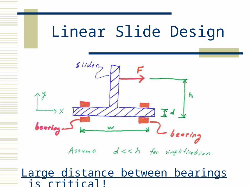
Linear Slide Design
Large distance between bearings is critical!
Exact Constraint Design: Robust Bearings at Low Cost
Use the minimum necessary number of constraints
How many bearings support a shaft? What is the problem with too many
constraints? What is the problem with too few?
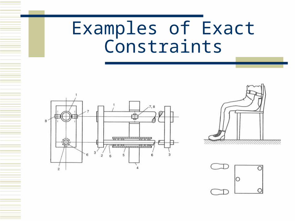
Examples of Exact Constraints
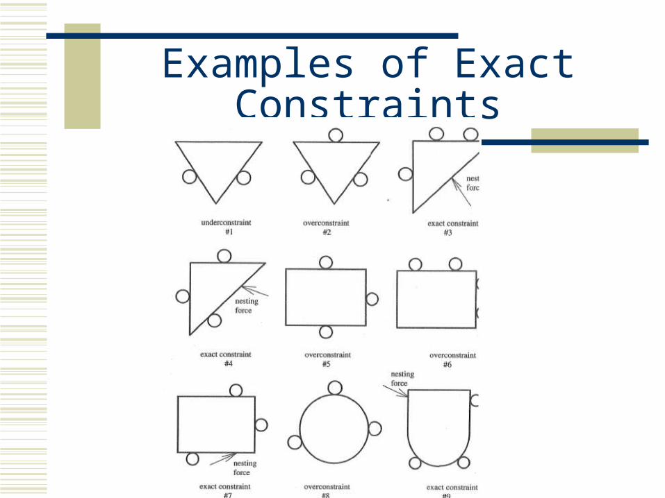
Examples of Exact Constraints
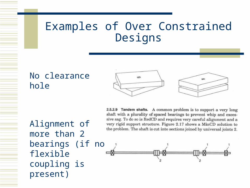
Examples of Over Constrained Designs
No clearance hole
Alignment of more than 2 bearings (if no flexible coupling is present)
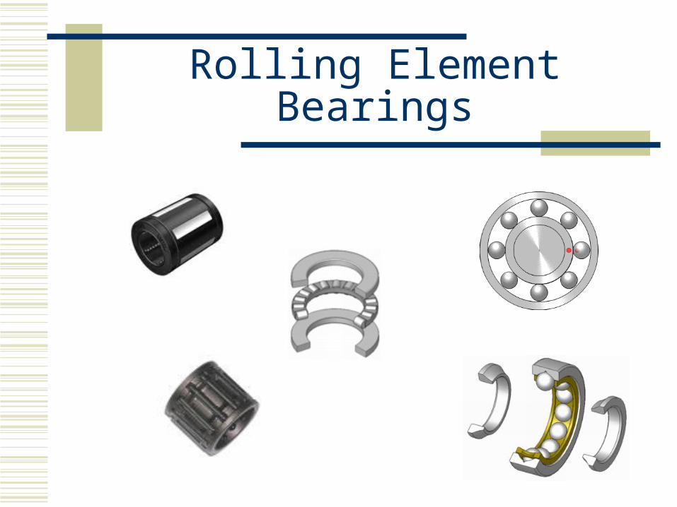
Rolling Element Bearings
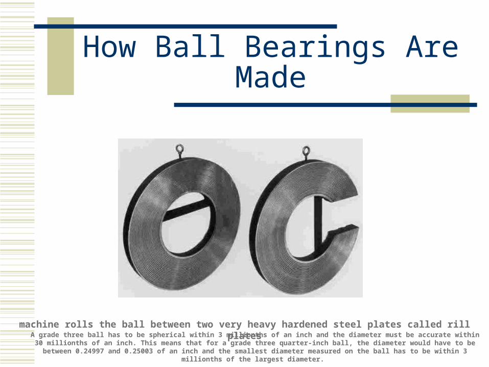
How Ball Bearings Are Made
machine rolls the ball between two very heavy hardened steel plates called rill platesA grade three ball has to be spherical within 3 millionths of an inch and the diameter must be accurate within 30 millionths of an inch. This
means that for a grade three quarter-inch ball, the diameter would have to be between 0.24997 and 0.25003 of an inch and the smallest diameter measured on the ball has to be within 3 millionths of the largest diameter.
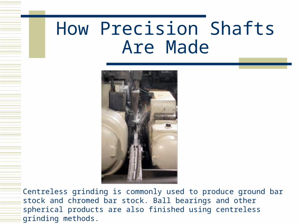
How Precision Shafts Are Made
Centreless grinding is commonly used to produce ground bar stock and chromed bar stock. Ball bearings and other spherical products are also finished using centreless grinding methods.
Design of Robust Structures
Just like bearing design but all 6 DOF are constrained
Rotations cause biggest problems Use large distance between contact points in
each plain of rotation. Contact points may not be obvious
Motion System Components
Bearings
Actuators
Control
Actuators
Every actuator has a Torque-Speed curve. Understanding the physics of the actuators is
necessary to understand the advantages and disadvantages of each type.
Static and dynamic analysis is necessary
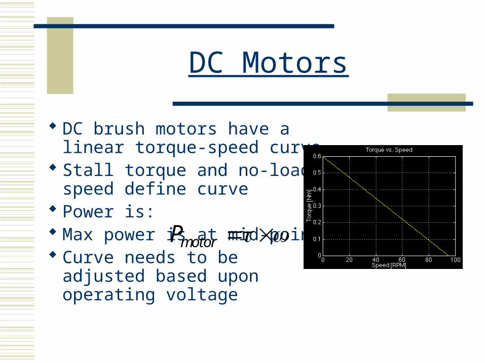
DC Motors
DC brush motors have a linear torque-speed curve
Stall torque and no-load speed define curve
Power is: Max power is at mid-point Curve needs to be adjusted
based upon operating voltage
motorP
Motion Analysis Categories
Quasi-Static Constant Velocity Dynamic analysis including acceleration and
deceleration Closed loop control
Analysis Guidelines
Proper Free Body Diagram (FBD) List assumptions
Indicate if conservative or not-conservative
Use Factor of Safety (F.S) for design choices, but not when comparing measured performance to predictions
Always include discussion section
Quasi-Static Analysis
Identifies minimum torque requirements to initiate motion
Used a lot in MAE3 but not always approrpaite for MAE156A.
Especially not appropriate when?
Constant Velocity Analysis
Easy to implement using Torque-Speed curve
Only valid if acceleration and deceleration duration are significantly shorter than constant velocity duration
How valid is this analysis for the robot contest?
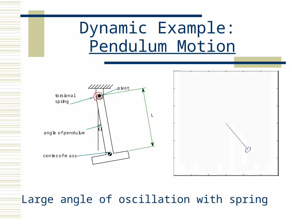
Dynamic Example: Pendulum Motion
Large angle of oscillation with spring
torsionalspring
pivot
center of mass
angle of pendulum
L
Dynamic Analysis
Apply F = ma Define initial conditions Solution methods:
1. ODE numerically (Euler method, Runga-Katta, other?) in Matlab
2. Use dynamic simulation program, such as Working Model, ProE, or other
Effective Inertia
For even a single DOF system there may be more than a single moving mass: There may be: A translating mass and rotating mass A gear reduction where one mass is moving
faster than the other
What is the inertia of the system?

Motion System Components
Bearings
Actuators
Control
Control Considerations
Precision Over-shoot Vibration Stability Control Theory is large field
But if you identify the source of the problem, you are 80% the way to a solution
Mechanical Issues Affecting Control
Gear Backlash Back drivable vs non-back drivable motors Driving large inertias System stiffness