Embed Size (px)
Citation preview
760 IEEE TRANSACTIONS ON IMAGE PROCESSING, VOL. 9, NO. 5, MAY 2000
Design of Orthogonal and Biorthogonal LappedTransforms Satisfying Perception Related Constraints
Helmut Bölcskei, Member, IEEE, Richard Heusdens, Rik Theunis, and Augustus J. E. M. Janssen
Abstract—We propose a new efficient method for the design oforthogonal and biorthogonal lapped transforms for image codingapplications. It is shown how perception related constraints suchas decay and smoothness of the filters’ impulse responses canbe incorporated in the optimization procedure. A decompositionof lapped transforms (orthogonal and biorthogonal) with 50%overlap leads to an efficient recursive optimization procedure,which is robust with respect to initial solutions. The importanceof this decomposition lies in the fact that it allows to decouplethe design of the even-symmetric and the odd-symmetric filtersand hence drastically reduces the number of variables to beoptimized. It furthermore reveals all the variables predeterminedby perception related and coding-efficiency related constraintsimposed on the filters. We present design and coding examplesdemonstrating the perceptual performance and the rate-distortionperformance of the resulting transforms.
Index Terms—Image coding, transform coding.
I. INTRODUCTION AND OUTLINE
I T is well known that the discrete cosine transform (DCT)[1], which is used in the JPEG image compression standard,
suffers especially at low bit rates from blocking effects. In audiocoding these blocking effects are perceived as clicking effects.In order to circumvent this drawback lapped orthogonal trans-forms (LOT’s) have been proposed [2]–[6]. The basic differ-ence between LOT’s and block transforms, such as the DCT, isthat the LOT basis functions are overlapping and therefore allow“smooth” transitions at the boundaries, which reduces or eveneliminates blocking effects.Although lapped transforms1 (LT’s) are very popular in
image coding, it seems that there are no efficient systematicprocedures for the design of perceptually constrained LT’s in
Manuscript received April 21, 1997; revised September 7, 1999. This workwas performed while the first author was on leave at Philips Research Labora-tories, Eindhoven, The Netherlands. This work was supported by FWF underGrants P10531-ÖPH and J1629-TEC and by Philips Research Laboratories,Eindhoven. The associate editor coordinating the review of this manuscript andapproving it for publication was Dr. Robert Forchheimer.H. Bölcskei is with the Information Systems Laboratory, Department of Elec-
trical Engineering, Stanford University, Stanford, CA 94305-9510 USA. He iscurrently on leave from the Department of Communications, Vienna Universityof Technology, Vienna, Austria.R. Heusdens is with the Department of Electrical Engineering, Circuits and
Systems Group, Delft University of Technology, 2628 CD Delft, The Nether-lands.R. Theunis is with Intreanet Multimedia Engineering, 1991 XD Velserbroek,
The Netherlands.A. J. E. M. Janssen is with Philips Research Laboratories, 5656 AA Eind-
hoven, The Netherlands.Publisher Item Identifier S 1057-7149(00)03574-0.
1The abbreviation LT stands for both lapped orthogonal and lapped biorthog-onal transforms with 50% overlap.
the literature. In this paper, we propose an efficient recursiveprocedure for the design of LT’s2 (orthogonal and biorthog-onal) with 50% overlap. We show how perceptually relevantconstraints such as decay and smoothness of the filters’impulse responses and coding-efficiency related constraintscan be incorporated systematically in the design procedure.Our approach is based on a decomposition of LT’s, whichallows to decouple the design of the even-symmetric and theodd-symmetric filters (transform basis functions) and hencedrastically reduces the number of variables to be optimized.It furthermore reveals all the variables predetermined by theconstraints imposed on the filters. In the approach we suggestthe even-symmetric filters are designed such that they satisfyperception related and coding-efficiency related constraints andthe odd-symmetric filters are derived from the even-symmetricfilters by means of a unitary transformation that keeps desirableproperties such as frequency selectivity, smoothness in the timedomain and so forth. Our decomposition leads to a new efficientrecursive optimization procedure, that is fast and robust withrespect to initial solutions. We even designed 256-channel LT’swith filters of length 512 using the method developed in thepaper. In general in image coding applications short filters aredesired. However, for audio coding applications it is of interestto consider the design of LT’s with long filters. It has beenshown in [7] that block transforms and LT’s can be interpretedas filter banks (FB’s). Since the concepts of FB theory allow anefficient formulation of our design problem, we shall treat thetransforms under consideration as perfect reconstruction (PR)FB’s. We will furthermore concentrate on one-dimensionaltransforms.1) Relation to Other Work: Malvar proposes a recursive
method for the design of LOT’s with maximum coding gain[6]. The algorithm described in [6] does, however, not take intoaccount perceptually relevant constraints such as smoothnessand decay of the filters’ impulse responses. Another approachdiscussed in [6], referred to as quasi-optimal LOT designalgorithm, starts from a valid LOT and applies a unitarytransformation to the LOT basis functions to obtain a new LOTwith specific properties. This algorithm does also not allowto systematically incorporate perception related constraints inthe design process. In [8] LOT’s with extended overlap havebeen discussed using a decomposition of polyphase matrices.All discussions in [6], [8] are limited to the orthogonal case.Furthermore, all these methods design both the even-symmetricand the odd-symmetric filters. Hence, they have twice the costof the methods proposed in this paper. Biorthogonal lapped2In the biorthogonal transforms under consideration the synthesis filters have
the same length as the analysis filters.
1057–7149/00$10.00 © 2000 IEEE
Authorized licensed use limited to: ETH BIBLIOTHEK ZURICH. Downloaded on January 28, 2010 at 12:16 from IEEE Xplore. Restrictions apply.
BÖLCSKEI et al.: DESIGN OF ORTHOGONAL AND BIORTHOGONAL LAPPED TRANSFORMS 761
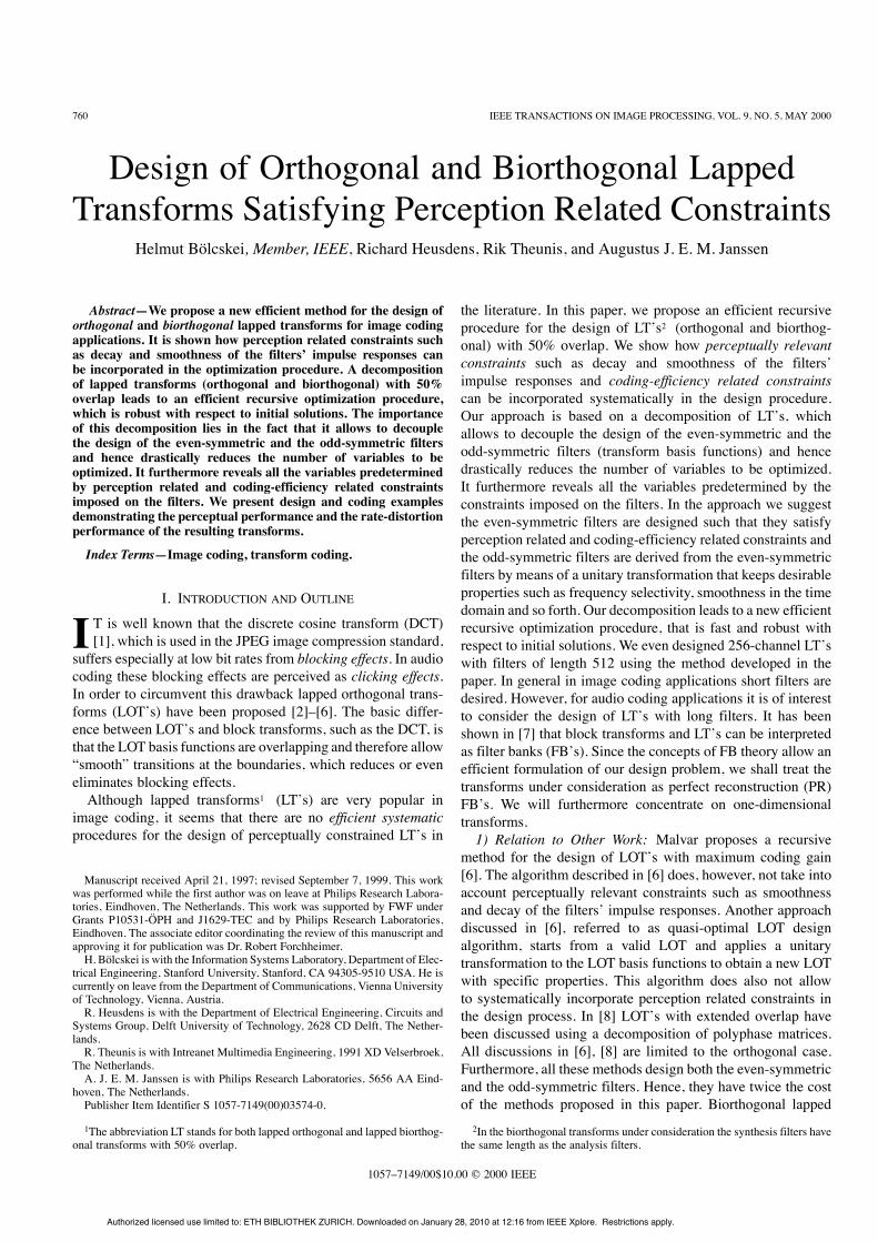
Fig. 1. Critically sampled -channel uniform FB.
transforms (BOLT’s) were discussed in [7], [9]. However, nodesign methods for BOLT’s have been reported. BOLT’s offermore design flexibility than LOT’s, since different restrictionson the analysis and synthesis filters can be imposed.2) Relation to Previous Own Work: In [10], [11] an ad-hoc
method for the design of LOT’s has been proposed. This methodis based on a decomposition of LOT’s with 50% overlap sim-ilar to that described in this paper. In the present paper we ex-tend this decomposition to the biorthogonal case and we intro-duce a systematic design method for LOT’s and BOLT’s basedon it. We furthermore describe the design of the unitary trans-formation providing the odd-symmetric filters. Besides that wedemonstrate the perceptual performance and the coding perfor-mance of the transforms designed using the proposed method.3) Organization of the Paper: In Section II we briefly re-
view FB’s and their relation to LT’s and we introduce some no-tation. In Section III we discuss perception related and coding-efficiency related constraints on the filters. We provide an im-portant decomposition of LT’s. Based on this decomposition,in Section IV, we formulate a new efficient recursive optimiza-tion procedure for orthogonal and biorthogonal LT’s. Finally, inSection V we give some design and coding examples demon-strating the perceptual performance and the rate-distortion per-formance of the resulting filters. Specifically, we demonstratethat the transforms designed using our method achieve the samerate-distortion performance as DCT-based schemes while beingsubstantially superior visually.Readers familiar with FB’s and LT’s can proceed to Section
III, where the new decomposition of LT’s and its consequencesand implications are presented. The core part of the paper con-cerning the optimization is presented in Section IV-A–C.
II. FILTER BANKS AND LAPPED TRANSFORMS
In this section, we briefly review critically sampled FB’s andtheir relation to LT’s [7], [12], [13].1) Critically Sampled Filter Banks: We consider an-channel FB [12]–[15] (see Fig. 1) with subsampling byin each channel, PR and zero delay, so that
where and denote the input and reconstructed signal,respectively. The transfer functions of the analysis and syn-thesis filters are and ( ), withcorresponding impulse responses and respectively.In Fig. 1, the are referred to as subband signals.
2) Polyphase Decomposition: The polyphase decomposi-tion of the analysis filters reads [12]–[15]
(1)
where
is the th polyphase component of the th analysis filterThe analysis polyphase matrix is defined as
[12]–[15]. The synthesis filterscan be similarly decomposed
(2)
with the synthesis polyphase components
The synthesis polyphase matrix is defined asA critically sampled FB satisfies
the PR condition if and only if [12]–[15]where is the
identity matrix. In the paraunitary case we have3 == and hence = In the biorthogonal
case the synthesis polyphase matrix is given by =Important numerical properties of the FB are determined by
its frame bounds [16]–[18] and The subband signalsof a FB satisfy
(3)with In the paraunitary case we have4
whereas in the biorthogonal case, the framebound ratio determines the “degree of nonorthogonality”of the FB and hence the amount of potential error blow-up dueto nonunitarity of the synthesis FB [16]–[18]. A good design3The paraconjugate of the matrix is defined as
[12], where stands for conjugate transposition.4Throughout the paper we assume that the are normalized, i.e.,for
Authorized licensed use limited to: ETH BIBLIOTHEK ZURICH. Downloaded on January 28, 2010 at 12:16 from IEEE Xplore. Restrictions apply.
762 IEEE TRANSACTIONS ON IMAGE PROCESSING, VOL. 9, NO. 5, MAY 2000
should aim at since indicates that theFB is ill-conditioned in the sense that small perturbations of thesubband signals can lead to an error amplification and hence toa big reconstruction error. Therefore, paraunitary FB’s have op-timum numerical properties. However, for certain applicationsthe constraints imposed on the filters in a paraunitary FB are toorestrictive and one has to resort to biorthogonal FB’s.The (tightest possible) frame bounds and of a FB are
given by the essential infimum and supremum, respectively, ofthe eigenvalues of the matrix[16]–[18]:
ess infess sup
In general, one has to perform an eigenanalysis offor We shall see later
that for the class of LT’s discussed in this paper the matrixis constant, i.e., it does not depend on
and therefore the calculation of the frame bounds reduces tothe eigenanalysis of a single constant matrix.3) Filter Banks and Lapped Transforms: FB’s provide de-
compositions into time-shifted versions of a set of basis func-tions [12], [13]. If the impulse responses have length the FBprovides a decomposition into LT’s with 50% overlap [7]. Pa-raunitary FB’s implement decompositions into LOT’s [7], [12],[13], whereas biorthogonal FB’s provide decompositions intoBOLT’s [7], [9]. In this paper, we shall consider both LOT’sand BOLT’s, simply referred to as LT’s hereafter.In the following, we assume that the analysis filters
are supported in the intervaland the synthesis filters are supported
in the interval The analysis polyphase matrixof a FB providing a decomposition into an LT is given by
where
......
......
(4)
and
......
......
(5)
are matrices. The synthesis polyphase matrix isgiven by
with the matrices
......
......
(6)
and
......
......
(7)For PR (with zero delay) it is necessary and sufficient that
[12], [13], which implies
(8)
and
(9)
where is the zero matrix.
III. ORTHOGONAL AND BIORTHOGONAL LAPPED TRANSFORMS
In this section, we formulate the constraints on the filters tobe designed. The constraints will be grouped into coding-effi-ciency related constraints and perception related constraints.Wepresent a decomposition of LT’s, which allows to formulate anefficient recursive design procedure (see Section IV). The im-portance of this decomposition lies in the fact that it allows todecouple the design of the even-symmetric and the odd-sym-metric filters and hence drastically reduces the number of vari-ables to be optimized. It furthermore reveals all the variablespredetermined by the constraints imposed on the filters. Thebasic idea of our approach is to design the even-symmetric fil-ters such that they satisfy perception related and coding-effi-ciency related constraints and to derive the odd-symmetric fil-ters from the even-symmetric filters by means of a unitary trans-formation that keeps desirable properties such as frequency se-lectivity, smoothness in the time domain and so forth.
A. Constraints on the Filters1) Coding-Efficiency Related Constraints: Let us start with
the coding-efficiency related constraints. In most practicalcoding systems the FB channels are coded mutually inde-pendent. Therefore, the analysis filters should have sufficientfrequency selectivity. In practical coding systems we shouldaim at designing the analysis filters such that their transferfunctions do not overlap too much. It is furthermore desirablethat all analysis filters except for the lowpass filter have a zeroat DC frequency. This guarantees that DC information can berepresented with only one channel, which leads to the mostefficient representation of, e. g., flat backgrounds.2) Perception-Related Constraints: We shall next discuss
constraints, which are important from a perceptual point ofview. Especially in image coding high frequency channels areoften roughly quantized. Since the DC component of images
Authorized licensed use limited to: ETH BIBLIOTHEK ZURICH. Downloaded on January 28, 2010 at 12:16 from IEEE Xplore. Restrictions apply.
BÖLCSKEI et al.: DESIGN OF ORTHOGONAL AND BIORTHOGONAL LAPPED TRANSFORMS 763
should be reconstructed as accurately as possible, it is desirablethat all synthesis filters except for the lowpass filter have a zeroat DC frequency, since otherwise errors introduced in the highfrequency channels will be spread out to the “important” DCcomponent.Since the contrast-sensitivity function of the human visual
system is roughly isotropic (rotation-invariant) [19], [20] andthe visual sensitivity of human observers decreases symmetri-cally at and on both sides of luminance changes [21], the syn-thesis filters should be linear phase filters.Long synthesis filters give rise to ringing effects around
edges and should be avoided. Therefore, we restrict our atten-tion to LT’s with 50% overlap. Another important requirementis that blocking effects should be eliminated or minimized. Thisimplies that the synthesis filter impulse responses should be“smooth” and decay to zero at the endpoints of their supportingintervals.
B. Decomposition of Lapped Transforms
In this section, we shall derive a decomposition of LT’s (or-thogonal and biorthogonal). This decomposition extends a sim-ilar decomposition for the orthogonal case [10], [11] and showsthat the design of LT’s can be decoupled into the design ofthe even-symmetric and the odd-symmetric filters. Thus, thenumber of variables to be optimized is drastically reduced. ForBOLT’s we derive a sufficient condition for the synthesis filtersto have the same length as the analysis filters. We furthermorediscuss the calculation of frame bounds.Let us start with the derivation of the decomposition. We con-
sider linear phase real-coefficient filtersof length with even. Thus, the shifted versions
of the basis functions are overlapping by 50% of the total length(LT’s with 50% overlap). The analysis polyphase matrix of thecorresponding FB can be written as where
and are given by (4) and (5), respectively. The synthesispolyphase matrix is where andare given by (6) and (7), respectively.It has been shown in [22] that in an -channel critically
sampled PR FB the analysis FB has linear phase filters if andonly if the synthesis FB has linear phase filters. Furthermore,for even, there are symmetric filters and anti-symmetric filters [22]. We thus setfor andfor Consequently,
for andfor
We furthermore partition the matrices and as
(10)
where and are matrices and andare matrices. From the linear phase property of thefilters it follows that
where is the counter-identity matrix given by
......
......
Note that postmultiplication by amounts to renumberingthe columns in reverse order, whereas premultiplication bycorresponds to renumbering the rows in reverse order.As already stated in the introduction of this section we want
to derive the odd-symmetric filters from the even-symmetric fil-ters by means of a transformation. Therefore, the matricesand containing the coefficients of the odd-symmetric filtersare written as and with somenonsingular matrix We shall next providea sufficient condition on the matrix guaranteeing that thesynthesis FB is FIR and that the synthesis filters have the samelength as the analysis filters.Proposition 3.1: Let be given by
(11)
For unitary,5 i.e., the synthesisFB is FIR and the synthesis filters have the same length as theanalysis filters. The corresponding synthesis polyphase matrix
is of the form6
(12)
with
(13)
Proof: According to [12]–[15] det withand is necessary and sufficient for the PR syn-
thesis FB to be FIR if the analysis FB is FIR. The condition detis equivalent to det Indeed, it
can easily be seen that for unitary
det det
which, of course, is a constant independent of This shows thatfor unitary the synthesis FB is FIR. Furthermore,
which using
for unitary gives
with
Thus, the synthesis filters have the same length as the analysisfilters.Note that in the orthogonal case the synthesis filters automati-
cally have the same length as the analysis filters. In the biorthog-5Since we are considering real-coefficient filters, the entries in are real-
valued.6Note that for unitary, we have
Authorized licensed use limited to: ETH BIBLIOTHEK ZURICH. Downloaded on January 28, 2010 at 12:16 from IEEE Xplore. Restrictions apply.
764 IEEE TRANSACTIONS ON IMAGE PROCESSING, VOL. 9, NO. 5, MAY 2000
onal case, however, this will in general not be true. Proposition3.1 shows that unitary is sufficient for the synthesis FB tobe FIR with synthesis filters having the same length as the anal-ysis filters. In the following, we shall always assume thatis unitary. Therefore, the transformation providing the transi-tion from the even-symmetric filters to the odd-symmetric fil-ters is a unitary transformation. We note that Proposition 3.1 isconsistent with the “orthogonality of overlapping blocks” con-dition [7] which is sufficient for the synthesisfilters to be FIR with the same length as the analysis filters. Itis easily seen that for unitary From Proposi-tion 3.1 we furthermore conclude that the design of LT’s can bereduced to the design of the matrices (or equivalentlythe even-symmetric filters) and the unitary matrix Fixingthe analysis FB, i.e., the matrix and calculating the syn-thesis FB according to (12) will not guarantee that the synthesisFB has the desired properties (zeros at DC frequency, frequencyselectivity, smoothness and decay of the filters). In the parauni-tary (orthogonal) case we have to design the matrices and
The decompositions (11) and (12) allow to focus on the de-sign of the filters with even symmetry or equivalently the ma-trices and Once these filters are designed we calculatethe matrix (see Section III-D) such that the odd-symmetricfilters inherit desirable properties from the even-symmetric fil-ters. We have thus split up the design into two stages, whichdrastically reduces the number of variables that have to be opti-mized at a time.1) PR Conditions: In the following, we shall always assume
that and The PR conditioncan be rephrased in terms of the matrices
and as
(14)
or equivalently using we have
(15)
2) Paraunitarity Conditions: The FB is paraunitary, i.e.,if and only if
(16)
or equivalently using we get
Note that for a paraunitary FB3) Frame Bounds: The frame bounds are obtained as
the infimum and the supremum, of the eigenvalues of the ma-trix We shall next show that in our case
is independent of and therefore the cal-culation of the frame bounds reduces to an eigenanalysis of asingle constant matrix. We have
(17)
Therefore
where denotes the eigenvalues of
C. Decomposition into Symmetric and Antisymmetric PartsIn this section, we further decompose the LT’s under consid-
eration by expressing the matrices and in terms of theirsymmetric and antisymmetric parts. This decomposition revealsthe variables that are predetermined due to the constraints onthe zeros of the analysis and the synthesis filters at (seeProposition 3.2). We have
and
where and denotes the even(odd)-symmetricpart of the matrix The following symmetry proper-ties will be used subsequently:
and
We furthermore have andEquations (11) and (12) can now be rewritten as
(18)
and
(19)
We note that such a decomposition already appears in [6] forthe special case of a LOT designed from a DCT. In [6] andare the even-symmetric and odd-symmetric DCT basis func-
tions, respectively. We will demonstrate subsequently that thedecompositions (18) and (19) are of importance in a more gen-eral context.1) PR Conditions: Using andin (14) it follows that the FB is PR if and only if
or equivalently using (15) we get
(20)
From (13) it follows that
(21)(22)
2) Paraunitarity Conditions: It can be shown that the FB isparaunitary (the LT is an LOT) if and only if
or equivalently(23)
Authorized licensed use limited to: ETH BIBLIOTHEK ZURICH. Downloaded on January 28, 2010 at 12:16 from IEEE Xplore. Restrictions apply.
BÖLCSKEI et al.: DESIGN OF ORTHOGONAL AND BIORTHOGONAL LAPPED TRANSFORMS 765
The frame bounds and of the FB are given by the min-imum and the maximum, respectively, of the eigenvalues of thematrixProposition 3.2: In an LT providing PR the analysis fil-
ters and the synthesis filtershave a zero at if and only
if7
(24)(25)
withProof: For with
wemust have for andfor We shall first
prove sufficiency of (24) and (25). Define the matricesand Using (20), we get
This implies that Equations (24) and (25) canbe rewritten as and where
is an vector with all ones andis an vector. Multiplying by
from the left and using yieldswhich implies that for Pro-ceeding the same way starting from and
it follows that for Thenecessity of (24) and (25) is shown as follows. Let us assumethat with Hence
which impliesthat with some constant Thusand using we get which implies thatthe first column of is constant. Setting (25)is shown. Starting from orequivalently it can be shown similarly, that
which implies that the first row of is constant. Set-ting (24) is proved. Finally, fromit follows that which concludes the proof.In the paraunitary case, where (24) with
is necessary and sufficient for all filters except forthe lowpass filter to have a zero at DC frequency. Note that theodd-symmetric filters have a zero at by definition.
D. Design of the Unitary TransformationIn this section, we show how the unitary matrix can be de-
signed. We assume that the even-symmetric filters are designedsuch that they satisfy the constraints discussed in Section III-A.One way to obtain the odd-symmetric filters is to modulate
the even-symmetric filters, which means that for an even-sym-metric filter the corresponding odd-symmetric filter
satisfies
so that(26)
Recall that the filters withare even-symmetric and the filters with7 denotes the th element in the th row of
are odd-symmetric. Letdiag Then (26) can be written as
(27)
This choice of together with combinedwith (14) or the equivalent conditions (15) will in general notyield a PR LT, since the conditions (9) are not automaticallysatisfied. One could, however, impose additional restrictions on
and such that the resulting transform has PR. How-ever, this amounts to imposing additional side constraints on theeven-symmetric filters. Clearly, the quality of the resulting fil-ters (frequency selectivity and so forth) will not be as good asthat of the filters obtained using our transformation approach.Since shifting the even-symmetric filters in frequency to ob-
tain the odd-symmetric filters will guarantee that the odd-sym-metric filters keep desirable properties of the even-symmetricfilters, such as frequency selectivity, smoothness of the impulseresponses and so forth, we shall try to approximate
by the matrix with unitary. A good ap-proximation to will guarantee that the odd-symmetric filters are approximately frequency-shifted versionsof the even-symmetric filters and thus share desirable propertiesof the even-symmetric filters. As we shall see later (see the de-sign examples in Section V) it is relatively easy to find a unitarymatrix that provides a good approximation.In general the row space of will not coincide with
the row space of In the case that the two rowspaces do not coincide we will approximate ina least-squares sense, i.e., we will approximateby the orthogonal projection of the row space ofonto the row space of This means that
so that is given by
(28)
Since and are of full rank (full rank offollows from the PR property of the FB [10], [11]) we concludethat is nonsingular, as required.In order to have unitary as required, we can apply a Gram-
Schmidt orthogonalization to either the rows or the columnsof For perceptual reasons, however, it is advantageous toapply the orthogonalization procedure to the rows of Thiscan be understood as follows. The Gram-Schmidt process saysthat if is a linearly independent set of vec-tors, then there exists an orthogonal set suchthat and is a linear combinationof for The are constructed by
Clearly, the idea of the Gram-Schmidt process is to subtractfrom every new vector its components in the directions that arealready settled and normalize it. As a consequence, the devia-tion of the orthogonalized vectors with respect to the originalnonprocessed vectors increases with increasing index, that
Authorized licensed use limited to: ETH BIBLIOTHEK ZURICH. Downloaded on January 28, 2010 at 12:16 from IEEE Xplore. Restrictions apply.
766 IEEE TRANSACTIONS ON IMAGE PROCESSING, VOL. 9, NO. 5, MAY 2000
is, for Nextconsider the construction of and assume that wehave ordered the even-symmetric analysis filters in suchthat the pass-band center-frequency of the frequency responsesincreases with increasing row index Obviously, the th rowof is only affected by and the th row of Sincethe sensitivity of the human visual system varies as a functionof spatial frequency in the sense that it is less sensitive to higherspatial frequencies than to lower spatial frequencies [19], [20],we conclude that errors, i.e., deviations from the ideal givenby (28) in the higher order rows of are less critical than er-rors in the lower order rows of This is so, since errors inthe higher order rows of will affect higher frequency filters.Thus the Gram-Schmidt procedure should be applied to the rowsrather than to the columns of starting with the first row, thenthe second one and so forth. We note that if the Gram-Schmidtprocess is applied to the columns of the matrix the errors,i.e., the deviations from the ideal lead to an error that is uni-formly distributed among all filters, which of course is not de-sirable.We finally show under what conditions on the matricesand the equation can be satis-
fied exactly.Proposition 3.3: The equation
is satisfied if and only if and
Proof: Assume that Wethen have Notingthat it follows fromthat = == which shows that is odd-symmetric.Similarly, it can be shown that is even-symmetric.Therefore, since both and are of full rank, we concludethat andMultiplying from the left with andusing the unitarity of it follows thatwhich implies that = =and henceConversely, assume that and
We then have == Hence, =
= == as required.
IV. RECURSIVE OPTIMIZATION OF LAPPED TRANSFORMS
In this section, we formulate a recursive optimization proce-dure for LT’s. We concentrate on the design of the even-sym-metric filters, since as explained in Section III-D the odd-sym-metric filters can be obtained from the even-symmetric filtersby means of a unitary transformation. We furthermore assumethat in the frequency domain the even-symmetric filters and theodd-symmetric filters are alternating. This means that the firstfilter (corresponding to center frequency 0) is even-symmetric,the second filter (corresponding to center frequency ) isodd-symmetric and so forth. The design procedure can equiva-lently be formulated for a different ordering of the filters.
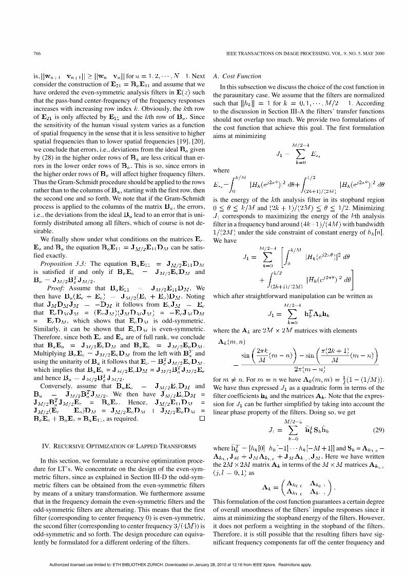
A. Cost FunctionIn this subsection we discuss the choice of the cost function in
the paraunitary case. We assume that the filters are normalizedsuch that for Accordingto the discussion in Section III-A the filters’ transfer functionsshould not overlap too much. We provide two formulations ofthe cost function that achieve this goal. The first formulationaims at minimizing
where
is the energy of the th analysis filter in its stopband regionand Minimizing
corresponds to maximizing the energy of the th analysisfilter in a frequency band around with bandwidth
under the side constraint of constant energy ofWe have
which after straightforward manipulation can be written as
where the are matrices with elements
for For we haveWe have thus expressed as a quadratic form in terms of thefilter coefficients and the matrices Note that the expres-sion for can be further simplified by taking into account thelinear phase property of the filters. Doing so, we get
(29)
where and =Here we have written
the matrix in terms of the matricesas
This formulation of the cost function guarantees a certain degreeof overall smoothness of the filters’ impulse responses since itaims at minimizing the stopband energy of the filters. However,it does not perform a weighting in the stopband of the filters.Therefore, it is still possible that the resulting filters have sig-nificant frequency components far off the center frequency and
Authorized licensed use limited to: ETH BIBLIOTHEK ZURICH. Downloaded on January 28, 2010 at 12:16 from IEEE Xplore. Restrictions apply.
BÖLCSKEI et al.: DESIGN OF ORTHOGONAL AND BIORTHOGONAL LAPPED TRANSFORMS 767
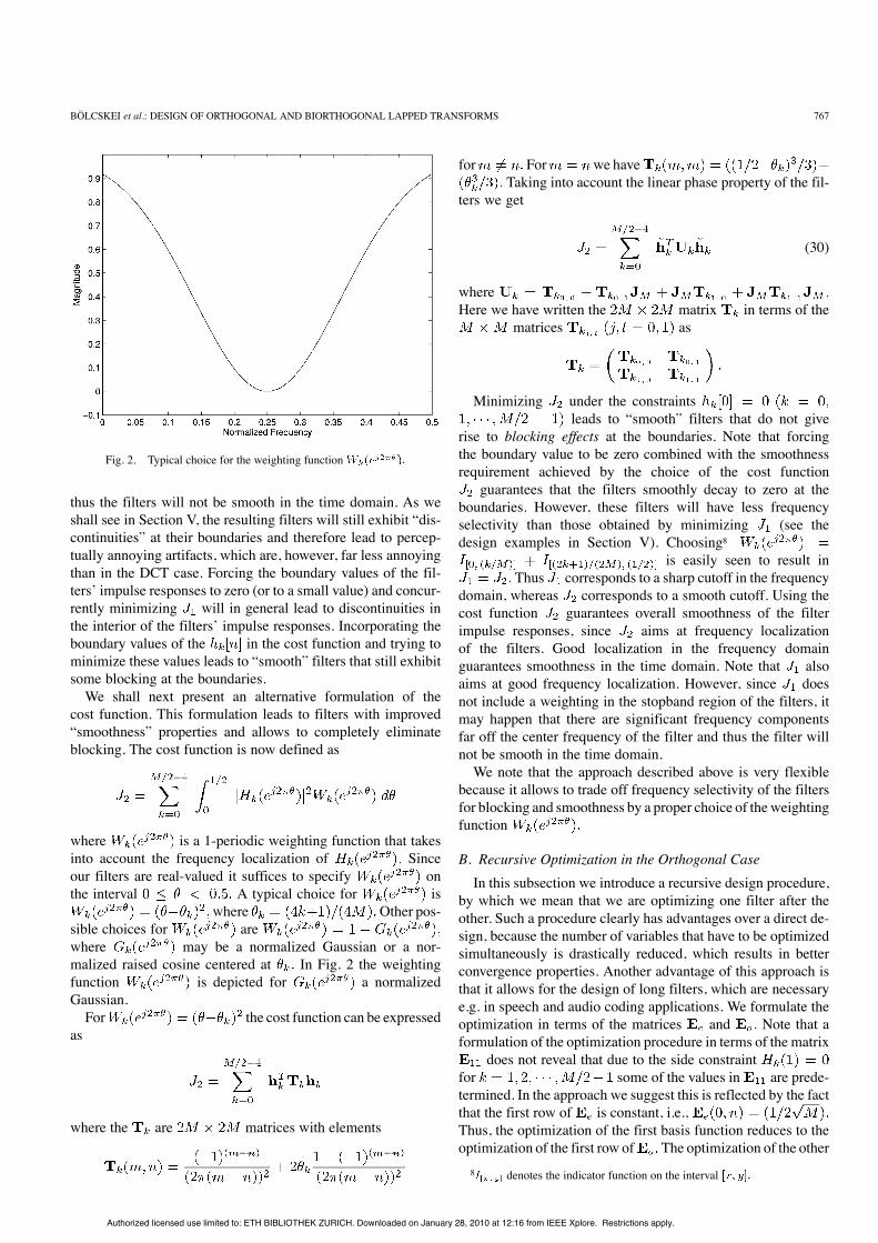
Fig. 2. Typical choice for the weighting function
thus the filters will not be smooth in the time domain. As weshall see in Section V, the resulting filters will still exhibit “dis-continuities” at their boundaries and therefore lead to percep-tually annoying artifacts, which are, however, far less annoyingthan in the DCT case. Forcing the boundary values of the fil-ters’ impulse responses to zero (or to a small value) and concur-rently minimizing will in general lead to discontinuities inthe interior of the filters’ impulse responses. Incorporating theboundary values of the in the cost function and trying tominimize these values leads to “smooth” filters that still exhibitsome blocking at the boundaries.We shall next present an alternative formulation of the
cost function. This formulation leads to filters with improved“smoothness” properties and allows to completely eliminateblocking. The cost function is now defined as
where is a 1-periodic weighting function that takesinto account the frequency localization of Sinceour filters are real-valued it suffices to specify onthe interval A typical choice for is
where Other pos-sible choices for arewhere may be a normalized Gaussian or a nor-malized raised cosine centered at In Fig. 2 the weightingfunction is depicted for a normalizedGaussian.For the cost function can be expressed
as
where the are matrices with elements
for For we haveTaking into account the linear phase property of the fil-
ters we get
(30)
whereHere we have written the matrix in terms of the
matrices as
Minimizing under the constraintsleads to “smooth” filters that do not give
rise to blocking effects at the boundaries. Note that forcingthe boundary value to be zero combined with the smoothnessrequirement achieved by the choice of the cost function
guarantees that the filters smoothly decay to zero at theboundaries. However, these filters will have less frequencyselectivity than those obtained by minimizing (see thedesign examples in Section V). Choosing8
is easily seen to result inThus corresponds to a sharp cutoff in the frequency
domain, whereas corresponds to a smooth cutoff. Using thecost function guarantees overall smoothness of the filterimpulse responses, since aims at frequency localizationof the filters. Good localization in the frequency domainguarantees smoothness in the time domain. Note that alsoaims at good frequency localization. However, since doesnot include a weighting in the stopband region of the filters, itmay happen that there are significant frequency componentsfar off the center frequency of the filter and thus the filter willnot be smooth in the time domain.We note that the approach described above is very flexible
because it allows to trade off frequency selectivity of the filtersfor blocking and smoothness by a proper choice of theweightingfunction
B. Recursive Optimization in the Orthogonal CaseIn this subsection we introduce a recursive design procedure,
by which we mean that we are optimizing one filter after theother. Such a procedure clearly has advantages over a direct de-sign, because the number of variables that have to be optimizedsimultaneously is drastically reduced, which results in betterconvergence properties. Another advantage of this approach isthat it allows for the design of long filters, which are necessarye.g. in speech and audio coding applications. We formulate theoptimization in terms of the matrices and Note that aformulation of the optimization procedure in terms of the matrix
does not reveal that due to the side constraintfor some of the values in are prede-termined. In the approach we suggest this is reflected by the factthat the first row of is constant, i.e.,Thus, the optimization of the first basis function reduces to theoptimization of the first row of The optimization of the other8 denotes the indicator function on the interval
Authorized licensed use limited to: ETH BIBLIOTHEK ZURICH. Downloaded on January 28, 2010 at 12:16 from IEEE Xplore. Restrictions apply.
768 IEEE TRANSACTIONS ON IMAGE PROCESSING, VOL. 9, NO. 5, MAY 2000
basis functions requires a simultaneous optimization of both thecorresponding rows in and The side constraints arisingfrom the paraunitarity of the FB are given by (23). The algo-rithm is as follows.• Step 1) Find that minimizes
or
where is a proper weighting factor, which can bechosen to be zero. The side constraints are given by— (eliminate blocking). This side constraintis to be used in combination with— (Normalization).
• Step 2) Set the basis function index to• Step 3) Find and that minimize
or
where is a proper weighting factor, which can bechosen to be zero. The side constraints are given by— (eliminate blocking). This side constraintis to be used in combination with— for (or-thogonality of rows of— for (or-thogonality of rows of—(normalized analysis filters, i.e.,
• Step 4) (next basis function).• Step 5) Stop if otherwise go back to Step 3.Choosing in Step 1 or in Step 3 not equal to zero
amounts to including the boundary value of the correspondingimpulse response in the cost function. Another possible choicefor the cost function results from including in the costfunction Then, clearly must not be a side con-straint any more. It is easily seen that there is no need to includethe condition on the zeros of the analysis filters at sincethis is already guaranteed by having a constant first row of(see Proposition 3.2). We note that this recursive approach doesnot guarantee that the optimization yields the global optimum.
C. Recursive Optimization in the Biorthogonal CaseIn the biorthogonal case a simultaneous optimization of the
analysis and the synthesis FB has to be performed, which meansthat we are optimizing the first analysis filter and the first syn-thesis filter concurrently and so on. Designing the analysis FBand calculating the corresponding synthesis FB does not guar-antee that the synthesis filters have any of the desired propertiesexcept for linear phase.From (13), it follows that there is a unique relation
between the analysis and the synthesis filters. So, one pos-sible approach to the design of a biorthogonal LT wouldbe to optimize (or equivalently and and toimpose restrictions on the synthesis filters determined by
This approachdoes, however, not allow for a recursive formulation sincein order to compute one of the synthesis filters according to(13) all analysis filters have to be known. Since, a recursivedesign procedure clearly has advantages over a direct one,we simultaneously optimize the rows in and and the
corresponding columns in and The cost function usedin the biorthogonal case includes the frequency selectivity ofall filters (analysis and synthesis) and “smoothness” of the syn-thesis filters’ impulse responses. Note that there is no need forthe analysis filters to decay to zero in the time domain. Thus aswe shall see in Section V in the biorthogonal case the analysisfilters will have better frequency selectivity than their orthog-onal counterparts. The optimization is formulated in terms ofthe matrices and Due to Proposition 3.2 thefirst row of and the first column of are predetermined.We set andThus the optimization of the first analysis filter and the firstsynthesis filter reduces to the optimization of the first row of
and the first column of The algorithm is as follows.• Step 1) Find and that minimize
or
where and are proper weighting factors andThe side constraints
are given by— (eliminate blocking). This side constraintis to be used in combination with— (normalized analysis fil-ters, i.e.,—
• Step 2) Set the basis function index to• Step 3) Find thatminimize
or
where and are proper weighting factors. The sideconstraints are given by— (eliminate blocking). This side constraintis to be used in combination with— for
(biorthogonality)— for
(biorthogonality)—(biorthogonality)—
for• Step 4) (next basis function).• Step 5) Stop if otherwise go back to Step 3.As in the orthogonal case, another possible choice for the cost
function is obtained by including the boundary value inThen, clearly must not be a side constraint
any more. Using this cost function often results in improvedconvergence properties.The advantage of biorthogonal transforms over orthogonal
transforms is increased design flexibility. This is mainly due tothe fact that we can impose different restrictions on the analysis
Authorized licensed use limited to: ETH BIBLIOTHEK ZURICH. Downloaded on January 28, 2010 at 12:16 from IEEE Xplore. Restrictions apply.
BÖLCSKEI et al.: DESIGN OF ORTHOGONAL AND BIORTHOGONAL LAPPED TRANSFORMS 769
Fig. 3. Sixteen-channel LOT: (a) transfer functions, (b) first filter, and (c)second filter.
and the synthesis filters. However, in hardware implementationsorthogonal transforms are preferred because of the saving of sil-icon area, which is due to the fact that the analysis filters areequal to the synthesis filters (up to time reversal and conjuga-tion). We note that the frame bound ratio determining im-portant numerical properties of the BOLT can be incorporatedin the cost function. However, this requires an eigenanalysis ofan matrix in each step of the iteration, which is compu-tationally expensive. Thus, it has to be checked after the designwhether the ratio is close to 1. We found that this is usuallythe case for the design procedures described in this paper.
D. CommentsWe conclude this section with some general remarks. The
proposed algorithms have been implemented in MATLAB. Wedesigned up to 256-channel LT’s with filters of length 512. Ouralgorithms were found to have excellent convergence proper-ties. They are furthermore very robust with respect to initial so-lutions. Typically, one can choose a random point as the initialsolution.
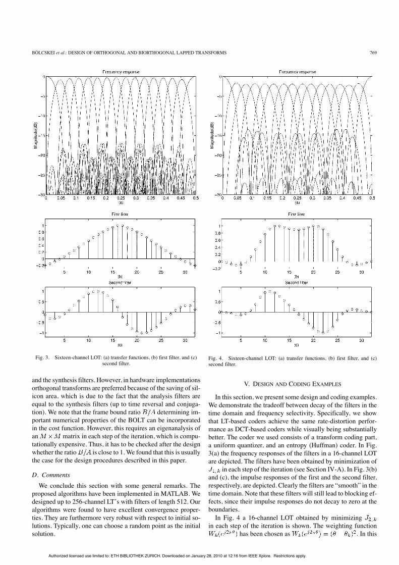
Fig. 4. Sixteen-channel LOT: (a) transfer functions, (b) first filter, and (c)second filter.
V. DESIGN AND CODING EXAMPLES
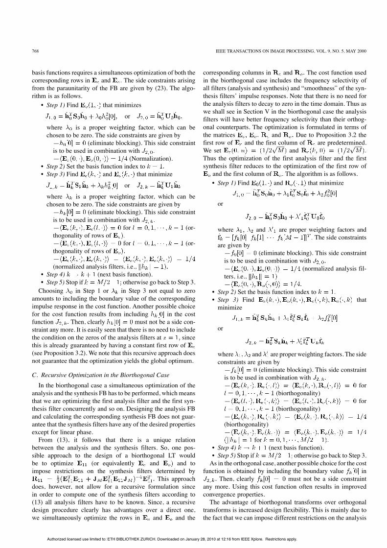
In this section, we present some design and coding examples.We demonstrate the tradeoff between decay of the filters in thetime domain and frequency selectivity. Specifically, we showthat LT-based coders achieve the same rate-distortion perfor-mance as DCT-based coders while visually being substantiallybetter. The coder we used consists of a transform coding part,a uniform quantizer, and an entropy (Huffman) coder. In Fig.3(a) the frequency responses of the filters in a 16-channel LOTare depicted. The filters have been obtained by minimization of
in each step of the iteration (see Section IV-A). In Fig. 3(b)and (c), the impulse responses of the first and the second filter,respectively, are depicted. Clearly the filters are “smooth” in thetime domain. Note that these filters will still lead to blocking ef-fects, since their impulse responses do not decay to zero at theboundaries.In Fig. 4 a 16-channel LOT obtained by minimizing
in each step of the iteration is shown. The weighting functionhas been chosen as In this
Authorized licensed use limited to: ETH BIBLIOTHEK ZURICH. Downloaded on January 28, 2010 at 12:16 from IEEE Xplore. Restrictions apply.
770 IEEE TRANSACTIONS ON IMAGE PROCESSING, VOL. 9, NO. 5, MAY 2000
(a)
(b)
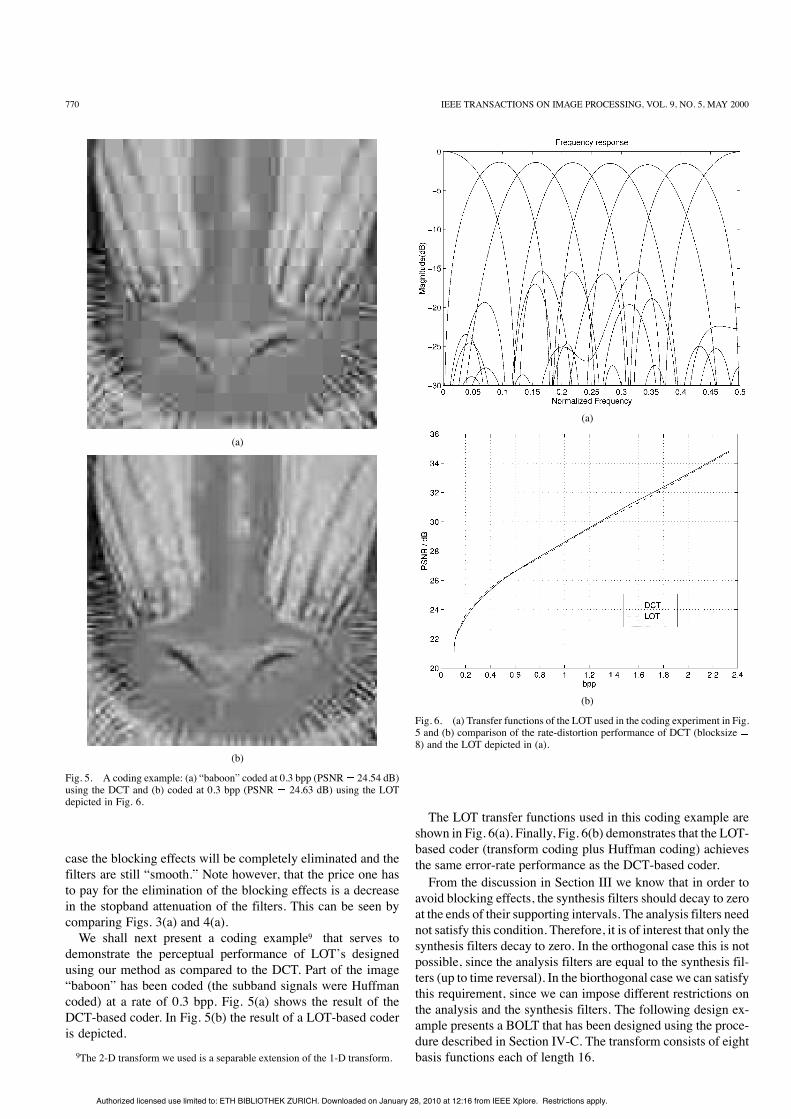
Fig. 5. A coding example: (a) “baboon” coded at 0.3 bpp (PSNR 24.54 dB)using the DCT and (b) coded at 0.3 bpp (PSNR 24.63 dB) using the LOTdepicted in Fig. 6.
case the blocking effects will be completely eliminated and thefilters are still “smooth.” Note however, that the price one hasto pay for the elimination of the blocking effects is a decreasein the stopband attenuation of the filters. This can be seen bycomparing Figs. 3(a) and 4(a).We shall next present a coding example9 that serves to
demonstrate the perceptual performance of LOT’s designedusing our method as compared to the DCT. Part of the image“baboon” has been coded (the subband signals were Huffmancoded) at a rate of 0.3 bpp. Fig. 5(a) shows the result of theDCT-based coder. In Fig. 5(b) the result of a LOT-based coderis depicted.9The 2-D transform we used is a separable extension of the 1-D transform.
(a)
(b)
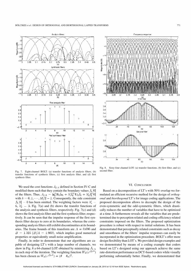
Fig. 6. (a) Transfer functions of the LOT used in the coding experiment in Fig.5 and (b) comparison of the rate-distortion performance of DCT (blocksize8) and the LOT depicted in (a).
The LOT transfer functions used in this coding example areshown in Fig. 6(a). Finally, Fig. 6(b) demonstrates that the LOT-based coder (transform coding plus Huffman coding) achievesthe same error-rate performance as the DCT-based coder.From the discussion in Section III we know that in order to
avoid blocking effects, the synthesis filters should decay to zeroat the ends of their supporting intervals. The analysis filters neednot satisfy this condition. Therefore, it is of interest that only thesynthesis filters decay to zero. In the orthogonal case this is notpossible, since the analysis filters are equal to the synthesis fil-ters (up to time reversal). In the biorthogonal case we can satisfythis requirement, since we can impose different restrictions onthe analysis and the synthesis filters. The following design ex-ample presents a BOLT that has been designed using the proce-dure described in Section IV-C. The transform consists of eightbasis functions each of length 16.
Authorized licensed use limited to: ETH BIBLIOTHEK ZURICH. Downloaded on January 28, 2010 at 12:16 from IEEE Xplore. Restrictions apply.
BÖLCSKEI et al.: DESIGN OF ORTHOGONAL AND BIORTHOGONAL LAPPED TRANSFORMS 771
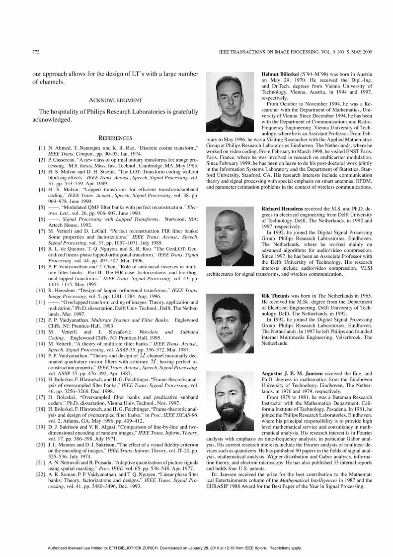
Fig. 7. Eight-channel BOLT: (a) transfer functions of analysis filters, (b)transfer functions of synthesis filters, (c) first analysis filter, and (d) firstsynthesis filter.
We used the cost functions defined in Section IV-C andmodified them such that they contain the boundary valuesof the filters. Thus,with Consequently, the side constraint
has been omitted. The weighting factors wereFig. 7(a) and (b) shows the transfer functions of
the analysis and synthesis filters, respectively. Fig. 7(c) and (d)shows the first analysis filter and the first synthesis filter, respec-tively. It can be seen that the impulse response of the first syn-thesis filter decays to zero at its boundaries, whereas the corre-sponding analysis filters still exhibit discontinuities at its bound-aries. The frame bounds of this transform are and
which implies good numericalproperties or equivalently small noise amplification.Finally, in order to demonstrate that our algorithms are ca-
pable of designing LT’s with a large number of channels, weshow in Fig. 8 a 64-channel LOT obtained by minimizingin each step of the iteration. The weighting functionhas been chosen as
Fig. 8. Sixty-four channel LOT: (a) transfer functions, (b) first filter, and (c)second filter.
VI. CONCLUSION
Based on a decomposition of LT’s with 50% overlap we for-mulated an efficient recursive method for the design of orthog-onal and biorthogonal LT’s for image coding applications. Theproposed decompositon allows to decouple the design of theeven-symmetric and the odd-symmetric filters, which drasti-cally reduces the number of variables that have to be optimizedat a time. It furthermore reveals all the variables that are prede-termined due to perception related and coding-efficiency relatedconstraints imposed on the filters. The proposed optimizationprocedure is robust with respect to initial solutions. It has beendemonstrated that perceptually related constraints such as decayand smoothness of the filters’ impulse responses can easily beincorporated in the optimization procedure. BOLT’s offer moredesign flexibility than LOT’s.We provided design examples andwe demonstrated by means of a coding example that codersbased on LT’s designed using our approach achieve the samerate-distortion performance as DCT-based coders while visuallyperforming substantially better. Finally, we demonstrated that
Authorized licensed use limited to: ETH BIBLIOTHEK ZURICH. Downloaded on January 28, 2010 at 12:16 from IEEE Xplore. Restrictions apply.
772 IEEE TRANSACTIONS ON IMAGE PROCESSING, VOL. 9, NO. 5, MAY 2000
our approach allows for the design of LT’s with a large numberof channels.
ACKNOWLEDGMENT
The hospitality of Philips Research Laboratories is gratefullyacknowledged.
REFERENCES[1] N. Ahmed, T. Natarajan, and K. R. Rao, “Discrete cosine transform,”
IEEE Trans. Comput., pp. 90–93, Jan. 1974.[2] P. Cassereau, “A new class of optimal unitary transforms for image pro-
cessing,” M.S. thesis, Mass. Inst. Technol., Cambridge, MA, May 1985.[3] H. S. Malvar and D. H. Staelin, “The LOT: Transform coding without
blocking effects,” IEEE Trans. Acoust., Speech, Signal Processing, vol.37, pp. 553–559, Apr. 1989.
[4] H. S. Malvar, “Lapped transforms for efficient transform/subbandcoding,” IEEE Trans. Acoust., Speech, Signal Processing, vol. 38, pp.969–978, June 1990.
[5] , “Modulated QMF filter banks with perfect reconstruction,” Elec-tron. Lett., vol. 26, pp. 906–907, June 1990.
[6] , Signal Processing with Lapped Transforms. Norwood, MA:Artech House, 1992.
[7] M. Vetterli and D. LeGall, “Perfect reconstruction FIR filter banks:Some properties and factorizations,” IEEE Trans. Acoust., Speech,Signal Processing, vol. 37, pp. 1057–1071, July 1989.
[8] R. L. de Queiroz, T. Q. Nguyen, and K. R. Rao, “The GenLOT: Gen-eralized linear-phase lapped orthogonal transform,” IEEE Trans. SignalProcessing, vol. 44, pp. 497–507, Mar. 1996.
[9] P. P. Vaidyanathan and T. Chen, “Role of anticausal inverses in multi-rate filter banks—Part II: The FIR case, factorizations, and biorthog-onal lapped transforms,” IEEE Trans. Signal Processing, vol. 43, pp.1103–1115, May 1995.
[10] R. Heusdens, “Design of lapped orthogonal transforms,” IEEE Trans.Image Processing, vol. 5, pp. 1281–1284, Aug. 1996.
[11] , “Overlapped transform coding of images: Theory, application andrealization,” Ph.D. dissertation, Delft Univ. Technol., Delft, The Nether-lands, Mar. 1997.
[12] P. P. Vaidyanathan, Multirate Systems and Filter Banks. EnglewoodCliffs, NJ: Prentice-Hall, 1993.
[13] M. Vetterli and J. Kovacevic, Wavelets and SubbandCoding. Englewood Cliffs, NJ: Prentice-Hall, 1995.
[14] M. Vetterli, “A theory of multirate filter banks,” IEEE Trans. Acoust.,Speech, Signal Processing, vol. ASSP-35, pp. 356–372, Mar. 1987.
[15] P. P. Vaidyanathan, “Theory and design of -channel maximally dec-imated quadrature mirror filters with arbitrary , having perfect re-construction property,” IEEE Trans. Acoust., Speech, Signal Processing,vol. ASSP-35, pp. 476–492, Apr. 1987.
[16] H. Bölcskei, F. Hlawatsch, and H. G. Feichtinger, “Frame-theoretic anal-ysis of oversampled filter banks,” IEEE Trans. Signal Processing, vol.46, pp. 3256–3268, Dec. 1998.
[17] H. Bölcskei, “Oversampled filter banks and predicative subbandcoders,” Ph.D. dissertation, Vienna Univ. Technol., Nov. 1997.
[18] H. Bölcskei, F. Hlawatsch, and H. G. Feichtinger, “Frame-theoretic anal-ysis and design of oversampled filter banks,” in Proc. IEEE ISCAS-96,vol. 2, Atlanta, GA, May 1996, pp. 409–412.
[19] D. J. Sakrison and V. R. Algazi, “Comparison of line-by-line and two-dimensional encoding of random images,” IEEE Trans. Inform. Theory,vol. 17, pp. 386–398, July 1971.
[20] J. L. Mannos and D. J. Sakrison, “The effect of a visual fidelity criterionon the encoding of images,” IEEE Trans. Inform. Theory, vol. IT-20, pp.525–536, July 1974.
[21] A. N. Netravali and B. Prasada, “Adaptive quantization of picture signalsusing spatial masking,” Proc. IEEE, vol. 65, pp. 536–548, Apr. 1977.
[22] A. K. Soman, P. P. Vaidyanathan, and T. Q. Nguyen, “Linear phase filterbanks: Theory, factorizations and designs,” IEEE Trans. Signal Pro-cessing, vol. 41, pp. 3480–3496, Dec. 1993.
Helmut Bölcskei (S’94–M’98) was born in Austriaon May 29, 1970. He received the Dipl.-Ing.and Dr.Tech. degrees from Vienna University ofTechnology, Vienna, Austria, in 1994 and 1997,respectively.From October to November 1994, he was a Re-
searcher with the Department of Mathematics, Uni-versity of Vienna. Since December 1994, he has beenwith the Department of Communications and Radio-Frequency Engineering, Vienna University of Tech-nology, where he is anAssistant Professor. From Feb-
ruary to May 1996, he was a Visiting Researcher with the Applied MathematicsGroup at Philips Research Laboratories Eindhoven, The Netherlands, where heworked on video coding. From February to March 1998, he visited ENST Paris,Paris, France, where he was involved in research on multicarrier modulation.Since February 1999, he has been on leave to do his post-doctoral work jointlyin the Information Systems Laboratory and the Department of Statistics, Stan-ford University, Stanford, CA. His research interests include communicationtheory and signal processing with special emphasis on smart antennas, OFDM,and parameter estimation problems in the context of wireless communications.
Richard Heusdens received the M.S. and Ph.D. de-grees in electrical engineering from Delft Universityof Technology, Delft, The Netherlands, in 1992 and1997, respectively.In 1992, he joined the Digital Signal Processing
Group, Philips Research Laboratories, Eindhoven,The Netherlands, where he worked mainly onadvanced algorithms for audio/video compression.Since 1997, he has been an Associate Professor withthe Delft University of Technology. His researchinterests include audio/video compression, VLSI
architectures for signal transforms, and wireless communication.
Rik Theunis was born in The Netherlands in 1965.He received the M.Sc. degree from the Departmentof Electrical Engineering, Delft University of Tech-nology, Delft, The Netherlands, in 1992.In 1992, he joined the Digital Signal Processing
Group, Philips Research Laboratories, Eindhoven,The Netherlands. In 1997 he left Philips and foundedInternet Multimedia Engineering, Velserbroek, TheNetherlands.
Augustus J. E. M. Janssen received the Eng. andPh.D. degrees in mathematics from the EindhovenUniversity of Technology, Eindhoven, The Nether-lands, in 1976 and 1979, respectively.From 1979 to 1981, he was a Bateman Research
Instructor with the Mathematics Department, Cali-fornia Institute of Technology, Pasadena. In 1981, hejoined the Philips Research Laboratories, Eindhoven,where his principal responsibility is to provide highlevel mathematical service and consultancy in math-ematical analysis. His research interest is in Fourier
analysis with emphasis on time-frequency analysis, in particular Gabor anal-ysis. His current research interests include the Fourier analysis of nonlinear de-vices such as quantizers. He has published 90 papers in the fields of signal anal-ysis, mathematical analysis, Wigner distribution and Gabor analysis, informa-tion theory, and electron microscopy. He has also published 33 internal reportsand holds four U.S. patents.Dr. Janssen received the prize for the best contribution to the Mathemat-
ical Entertainments column of the Mathematical Intelligencer in 1987 and theEURASIP 1988 Award for the Best Paper of the Year in Signal Processing.
Authorized licensed use limited to: ETH BIBLIOTHEK ZURICH. Downloaded on January 28, 2010 at 12:16 from IEEE Xplore. Restrictions apply.


![On the Zeros of Daubechies Orthogonal and Biorthogonal ... · wavelets were proved to reside inside the unit circle [5], and better limits for these roots based on a generalization](https://img.pdfslide.net/doc/110x75/5e8c0ab1eeeec952fe19f2dd/on-the-zeros-of-daubechies-orthogonal-and-biorthogonal-wavelets-were-proved.jpg)