Embed Size (px)
Citation preview

1
Design of
Rain water Harvesting
Scheme at Raila
2
TABLE OF CONTENTS
1. CHAPTER ONE: INTRODUCTION 3
1.1 INTRODUCTION 3
2. CHAPTER TWO: RAIN WATER HARVESTING 7
2.1 INTRODUCTION 7
2.2 ADVANTAGES OF USING RAINWATER 8
2.3 ARTIFICIAL RECHARGING 9
2.4 AMOUNT OF WATER NEEDED TO SATISFY THE NEEDS 15
2.5 AMOUNT OF WATER THAT CAN BE COLLECTED 18
3.0 CHAPTER THREE : ROOF TOP RAIN WATER HARVESTING 26
3.1 INTRODUCTION 26
3.2 WATER QUALITY CONSIDERATION 30
4..0 CHAPTER FOUR : METHODOLOGY OF RAINWATER 32
HARVASTING SYSTEM
4.1 SYSTEM COMPONENT 32
5.0 CHAPTER FIVE : DESIGN TO STORAGE ,SETTLEMENT 42
TANK AND RECHARGE STRUCTURE
5.1 DESIGN STORAGE TANKS 42

3
5.2 DESIGN PARAMETERS FOR SETTLEMENT TANK 44
5.3 DESIGN OF RECHARGE STRUCTURES 46
6.0 CHAPTER SIX: CASE STUDISE 55
CHAPTER ONE: INTRODUCTION
1.1Introduction:
4
In spite of astonishing achievements in the field of Science & Technology, nature
remains to be a mystery for human beings. Though water is also being obtained through
desalination, artificial rain by cloud seeding etc. in some of the developed countries, the
shortage of water even for drinking purpose is a perpetual phenomenon throughout the
world, especially in developing and underdeveloped countries. India is likely to
experience “Water Stress” from the year 2007 onwards. It will be pertinent to shift the
thrust of the policies from “Water Development” to “Sustainable Water Development”. A
vital element of this shift in strategy is the increasing importance of Water Harvesting
and Artificial recharge of Ground Water.
Countries like Slovakia, Israel, use water about 4-5 times before disposing off. However,
in India it is used only once before being disposed. This is certainly not a very
encouraging situation.
The never-ending exchange of water from the atmosphere to the oceans and back again is
known as the hydrologic cycle. This cycle is the source of all forms of precipitation (hail,
rain, sleet and snow), and thus of all water. Water and moisture stored in streams, lakes,
and soil evaporates while water stored in plants transpires to form clouds, which store the
water in the atmosphere.
Making the most efficient use of our limited and precious resources is essential. This
includes using appliances and plumbing fixtures that conserve water, not wasting water
and taking advantage of alternative water sources such as grey water reuse and rainwater
harvesting.
Water is essential for life and plays a major role in creating earth’s climate. By modifying
land use, the proportion of the different pathways, evaporation, percolation and run off
change. A change in evaporation from a region has impacts upon climate. Changes in
percolation change ground water availability, both for humans, and natural springs and
streams. Changes in run off will change stream flow and erosion patterns, which in turn
modifies the sediment load of stream.
5
Rainwater harvesting is the activity of direct collection of rainwater. The Rainwater so
collected can be stored for direct use or can be recharged into the ground water for future
use. The main goal is to minimize flow of rainwater through drains / nallahas to the
rivers and then to sea without making any use of the same. It is a known fact that the
ground water level is depleting and going down day by day in the last decades. The
rivers, lakes and ground water are the secondary sources of water. In absence of rainwater
harvesting, we depend entirely on such secondary sources of water and in the process it is
forgotten that rain is the ultimate source that feeds to these secondary sources. The value
of this important primary source of water must not be lost. Rainwater harvesting means
to understand the value of rain and to make optimum use of rainwater at the place where
it falls.
The need: Rain Water Harvesting can be understood by the fact that even CHIRAPUNJI,
which receives about 11000 mm rain fall annually, suffers from acute shortage of
drinking water due to the reasons that Rain water is not harvested and is allowed to drain
away.
The annual rainfall over India is computed to be 1170 mm, which is much higher than the
global average of 800 mm. However, this rainfall in India occurs during short periods of
high intensity. Such high intensity and short duration makes most of the rain falling on
the surface to flow away leaving little scope for recharging of ground water. This results
in lack of water in most part of the country even for domestic uses.
There are two types of rainwater harvesting:
Storage of rainwater on surface
Recharge to ground water
Roof top rainwater harvesting consists of collecting, storing and using rooftop rainwater
from houses or any construction. Rainwater harvesting can also be collecting, filtering
and recharging ground water through percolation pits, open wells or bore wells.
6
The artificial recharge to ground water is a process by which the ground water reservoir
is augmented at a rate exceeding that obtained under natural conditions of replenishment.
Any man made scheme or facility that adds water to an aquifer may be considered to be
an artificial recharge system.
Artificial recharge techniques normally address to following issues:
To enhance the sustainable yield in areas where over development has
depleted the aquifer.
To utilize the rainfall runoff, that goes to sewer or storm water drain.
Storage of excess surface water for future requirements, since these
requirements often change within a season or a period.
Surface water is inadequate to meet the demand and it is met by ground
water.
Due to rapid urbanization, infiltration of rainwater into the sub soil has
decreased drastically and recharge of ground water has diminished.
To arrest seawater ingress.
To improve the vegetation cover and reduce flood hazard.
To raise the water levels in wells and bore wells those are drying up.
To remove bacteriological and other impurities from sewage water and
waste- water so that water is suitable for reuse.
To improve the quality of existing ground water through dilution.
To reduce power consumption used to withdraw water.
The basic purpose of artificial recharge of ground water is to restore supplies from
aquifers depleted due to excessive ground water usage.
The sub-surface reservoirs are very attractive and technically feasible alternatives for
storing surplus monsoon run off. They can store substantial quantity of water. The sub-
surface geological formations may be considered as warehouse for storing water that
7
come from sources located on the land surface. Besides suitable litho logical conditions,
other considerations for creating sub-surface storages are favorable geological structures
and physiographic units, whose dimensions and shape will allow retention of substantial
volume of water in porous and permeable formations. The sub-surface reservoirs, located
in suitable hydro geological situations, are environment friendly and economically viable
proposition. The sub-surface storages have advantages of being free from the adverse
effects like inundation of large surface area, loss of cultivable land, displacement of local
populations, substantial evaporation losses and sensitivity, to earthquakes. No gigantic
structures are needed to store water.
The storage of rainwater on surface is a traditional technique and structures used were
underground tanks, ponds, check dams, weirs etc. Recharge to ground water is another
concept of rain water harvesting and the structures generally used are:
Pits
Trenches
Dug Wells
Hand pumps
Recharge wells
Recharge shafts
Lateral shafts with bore wells
Spreading techniques
It is needed to implement measures to make sure that rainwater falling over a
region is tapped to a maximum possible extent through rainwater harvesting,
either by recharging it into the ground water resources or storing it for direct use.
CHAPTER TWO: RAIN WATER HARVESTING
2.1Introduction
Water scarcity is a serious problem throughout the world for both urban and rural
communities. More and more water is required for domestic, construction and industrial
8
use. The rate of withdrawal is far in excess of the rate of recharging the water table. In
India, water is considered divine and referred to as thirtha. But, there is nothing holy in
our treatment of our water sources. Pollution and overexploitation have shrunk the
availability of clean and potable water to a trickle.
Urbanization has resulted in overexploitation of ground water, reduction in open soil
surface and water infiltration rate and a resultant deterioration in water quality.
Apartments and industrial units face acute water shortage forcing them to spend
considerable amounts of money to purchase water from municipal and private water
suppliers. The rural scenario is equally grim. The population explosion necessitates a
proportionate increase in food production, which in turn demands more land, more
fertilizers and pesticides and more water.
The water policy of the Government of India puts a norm of 180 litres per capita for our
domestic needs. But it is not possible to supply even 100 litres per day even in urban
areas. 30 million Indians spread out over an area of 7 lakh sq. km., mostly in the west and
North West regions; face an acute scarcity of potable water especially in the summer
months.
The main source is precipitation, in the form of rain or snow. The annual rainfall in India
is 400 million hectare meter. This rainwater can be used to recharge the ground water, by
adopting a simple technique called rainwater harvesting. Rainwater harvesting means
making use of each and every drop of rainwater to recharge the groundwater, by directing
the rainfall to go into the well or under the ground, without wasting the rainwater.
India uses only 10-20 percent of its annual rainfall. When it rains, only a fraction of the
water percolates and reaches the ground water aquifers, while the major part of the
rainfall drains out as run-off and goes unused into the ocean. Further, lack of adequate
storage facilities necessitate water being let into the sea to prevent breaching and
flooding. The increasing numbers and depth of bore wells and wells and their unrestricted
use threaten India's ground water resources.

9
2.2 Advantages of using rainwater
Rainwater harvesting promotes self-sufficiency and fosters an appreciation for
water as a resource. It also promotes water conservation.
Rainwater harvesting also conserves energy as the energy input needed to operate
a centralized water system is bypassed. Many systems require only a small pump
to create water pressure in household pipes.
Local erosion and flooding from impervious cover associated with buildings is
lessened as a portion of local rainfall is diverted into collection tanks.
Rainwater is one of the purest sources of water available. Its quality almost
always exceeds that of ground or surface water.
It does not come into contact with soil or rocks where it can dissolve minerals and
salts nor does it come into contact with many of the pollutants that are often
discharged into local surface waters or contaminate ground water supplies
Rainwater is soft. It can significantly lower the quantity of detergents and soaps
needed for cleaning. Soap scum and hardness deposits do not occur.
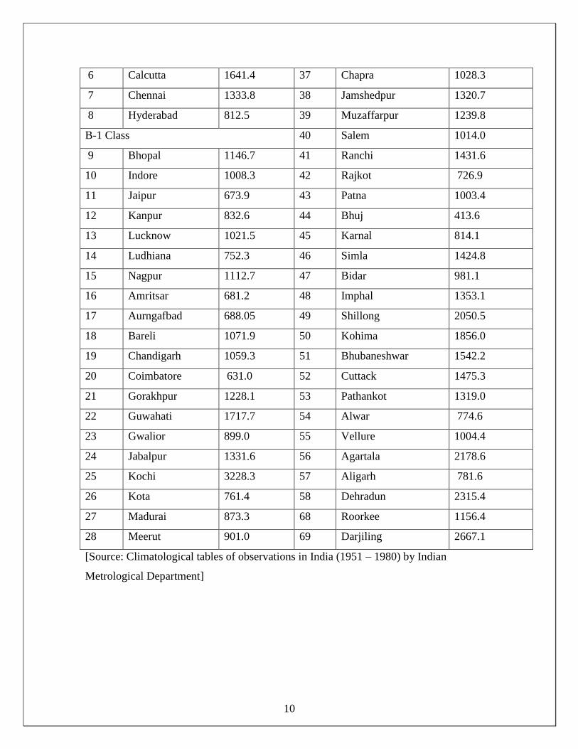
Table 2.1 Rainfall data for Major Cities in India
S.No. City Annual rain
fall (mm) ®
S.No. City Annual rain fall
(mm) ®
A-1 Class 29 Solapur 750..8
1 Mumbai 2146.6 30 Thiruvananthapuram 1827.7
2 New Delhi
(Safdarjung)
797.3 31 Tiruchirappali 880.2
3 New Delhi
(Palam)
794.0 32 Varanasi 1025.4
A- Class 33 Vishakhapatnam 968.8
4 Ahmedabad 803.4 34 Port Blair 3168.8
5 Bangalore 970.0 35 Dibrugarh 2588.7
C- Class 36 Tezpur 1768.3
10
6 Calcutta 1641.4 37 Chapra 1028.3
7 Chennai 1333.8 38 Jamshedpur 1320.7
8 Hyderabad 812.5 39 Muzaffarpur 1239.8
B-1 Class 40 Salem 1014.0
9 Bhopal 1146.7 41 Ranchi 1431.6
10 Indore 1008.3 42 Rajkot 726.9
11 Jaipur 673.9 43 Patna 1003.4
12 Kanpur 832.6 44 Bhuj 413.6
13 Lucknow 1021.5 45 Karnal 814.1
14 Ludhiana 752.3 46 Simla 1424.8
15 Nagpur 1112.7 47 Bidar 981.1
16 Amritsar 681.2 48 Imphal 1353.1
17 Aurngafbad 688.05 49 Shillong 2050.5
18 Bareli 1071.9 50 Kohima 1856.0
19 Chandigarh 1059.3 51 Bhubaneshwar 1542.2
20 Coimbatore 631.0 52 Cuttack 1475.3
21 Gorakhpur 1228.1 53 Pathankot 1319.0
22 Guwahati 1717.7 54 Alwar 774.6
23 Gwalior 899.0 55 Vellure 1004.4
24 Jabalpur 1331.6 56 Agartala 2178.6
25 Kochi 3228.3 57 Aligarh 781.6
26 Kota 761.4 58 Dehradun 2315.4
27 Madurai 873.3 68 Roorkee 1156.4
28 Meerut 901.0 69 Darjiling 2667.1
[Source: Climatological tables of observations in India (1951 – 1980) by Indian
Metrological Department]
11
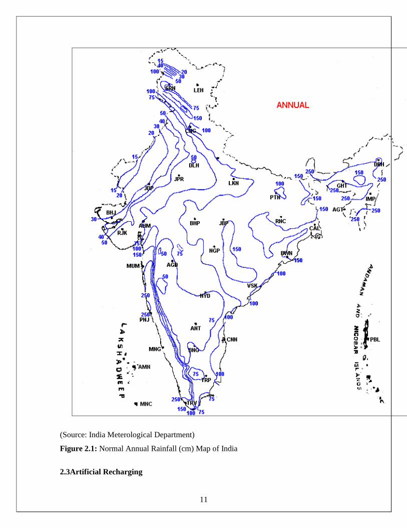
(Source: India Meterological Department)
Figure 2.1: Normal Annual Rainfall (cm) Map of India
2.3Artificial Recharging
12
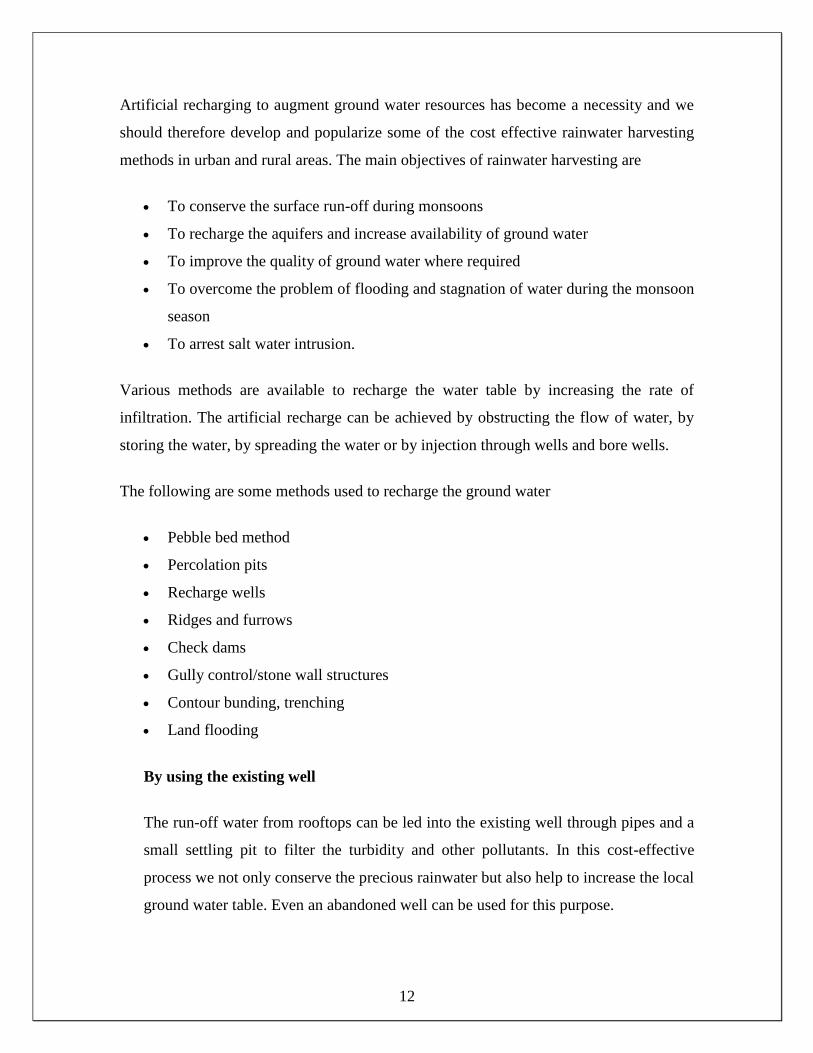
Artificial recharging to augment ground water resources has become a necessity and we
should therefore develop and popularize some of the cost effective rainwater harvesting
methods in urban and rural areas. The main objectives of rainwater harvesting are
To conserve the surface run-off during monsoons
To recharge the aquifers and increase availability of ground water
To improve the quality of ground water where required
To overcome the problem of flooding and stagnation of water during the monsoon
season
To arrest salt water intrusion.
Various methods are available to recharge the water table by increasing the rate of
infiltration. The artificial recharge can be achieved by obstructing the flow of water, by
storing the water, by spreading the water or by injection through wells and bore wells.
The following are some methods used to recharge the ground water
Pebble bed method
Percolation pits
Recharge wells
Ridges and furrows
Check dams
Gully control/stone wall structures
Contour bunding, trenching
Land flooding
By using the existing well
The run-off water from rooftops can be led into the existing well through pipes and a
small settling pit to filter the turbidity and other pollutants. In this cost-effective
process we not only conserve the precious rainwater but also help to increase the local
ground water table. Even an abandoned well can be used for this purpose.
13
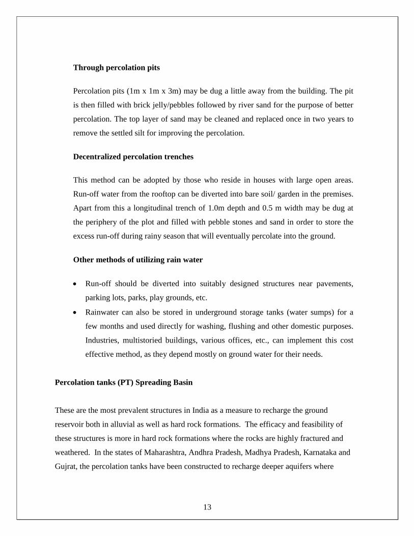
Through percolation pits
Percolation pits (1m x 1m x 3m) may be dug a little away from the building. The pit
is then filled with brick jelly/pebbles followed by river sand for the purpose of better
percolation. The top layer of sand may be cleaned and replaced once in two years to
remove the settled silt for improving the percolation.
Decentralized percolation trenches
This method can be adopted by those who reside in houses with large open areas.
Run-off water from the rooftop can be diverted into bare soil/ garden in the premises.
Apart from this a longitudinal trench of 1.0m depth and 0.5 m width may be dug at
the periphery of the plot and filled with pebble stones and sand in order to store the
excess run-off during rainy season that will eventually percolate into the ground.
Other methods of utilizing rain water
Run-off should be diverted into suitably designed structures near pavements,
parking lots, parks, play grounds, etc.
Rainwater can also be stored in underground storage tanks (water sumps) for a
few months and used directly for washing, flushing and other domestic purposes.
Industries, multistoried buildings, various offices, etc., can implement this cost
effective method, as they depend mostly on ground water for their needs.
Percolation tanks (PT) Spreading Basin
These are the most prevalent structures in India as a measure to recharge the ground
reservoir both in alluvial as well as hard rock formations. The efficacy and feasibility of
these structures is more in hard rock formations where the rocks are highly fractured and
weathered. In the states of Maharashtra, Andhra Pradesh, Madhya Pradesh, Karnataka and
Gujrat, the percolation tanks have been constructed to recharge deeper aquifers where
14
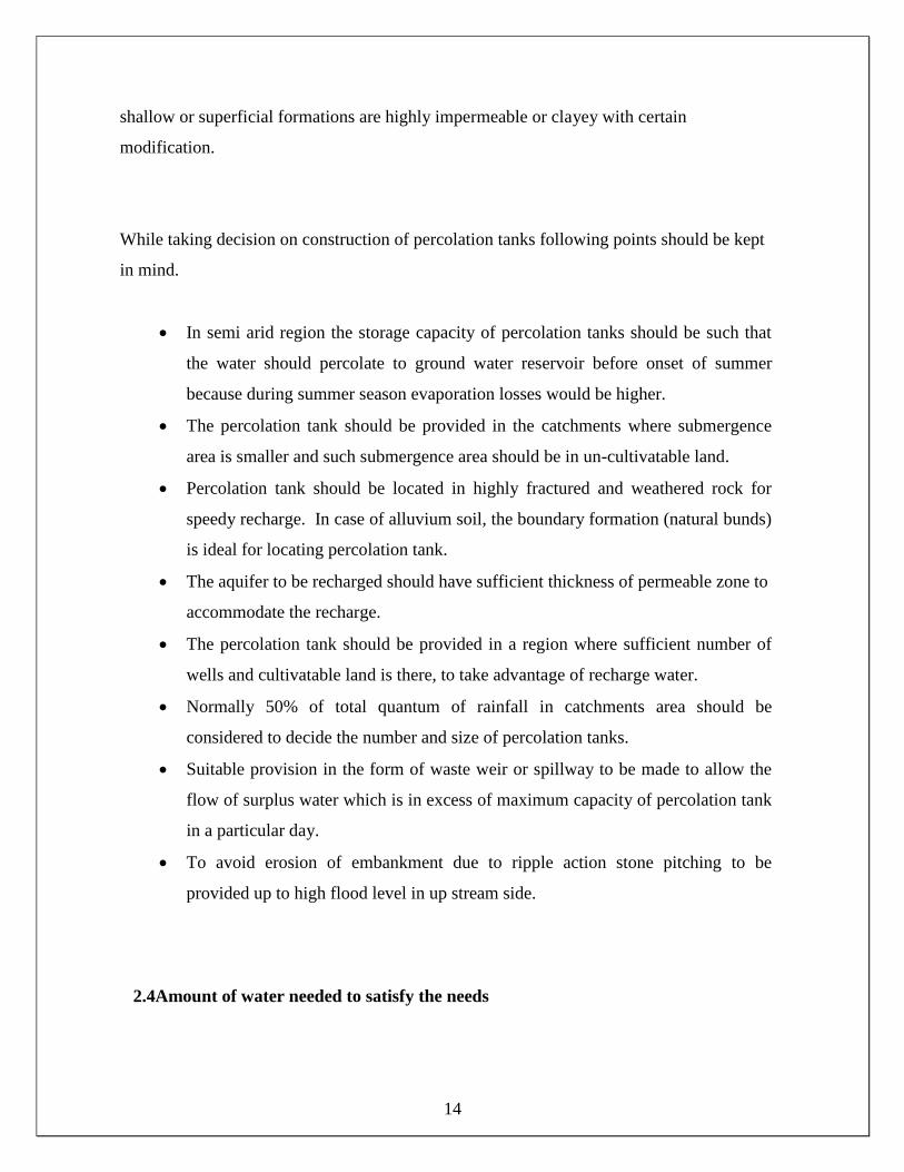
shallow or superficial formations are highly impermeable or clayey with certain
modification.
While taking decision on construction of percolation tanks following points should be kept
in mind.
In semi arid region the storage capacity of percolation tanks should be such that
the water should percolate to ground water reservoir before onset of summer
because during summer season evaporation losses would be higher.
The percolation tank should be provided in the catchments where submergence
area is smaller and such submergence area should be in un-cultivatable land.
Percolation tank should be located in highly fractured and weathered rock for
speedy recharge. In case of alluvium soil, the boundary formation (natural bunds)
is ideal for locating percolation tank.
The aquifer to be recharged should have sufficient thickness of permeable zone to
accommodate the recharge.
The percolation tank should be provided in a region where sufficient number of
wells and cultivatable land is there, to take advantage of recharge water.
Normally 50% of total quantum of rainfall in catchments area should be
considered to decide the number and size of percolation tanks.
Suitable provision in the form of waste weir or spillway to be made to allow the
flow of surplus water which is in excess of maximum capacity of percolation tank
in a particular day.
To avoid erosion of embankment due to ripple action stone pitching to be
provided up to high flood level in up stream side.
2.4Amount of water needed to satisfy the needs
15
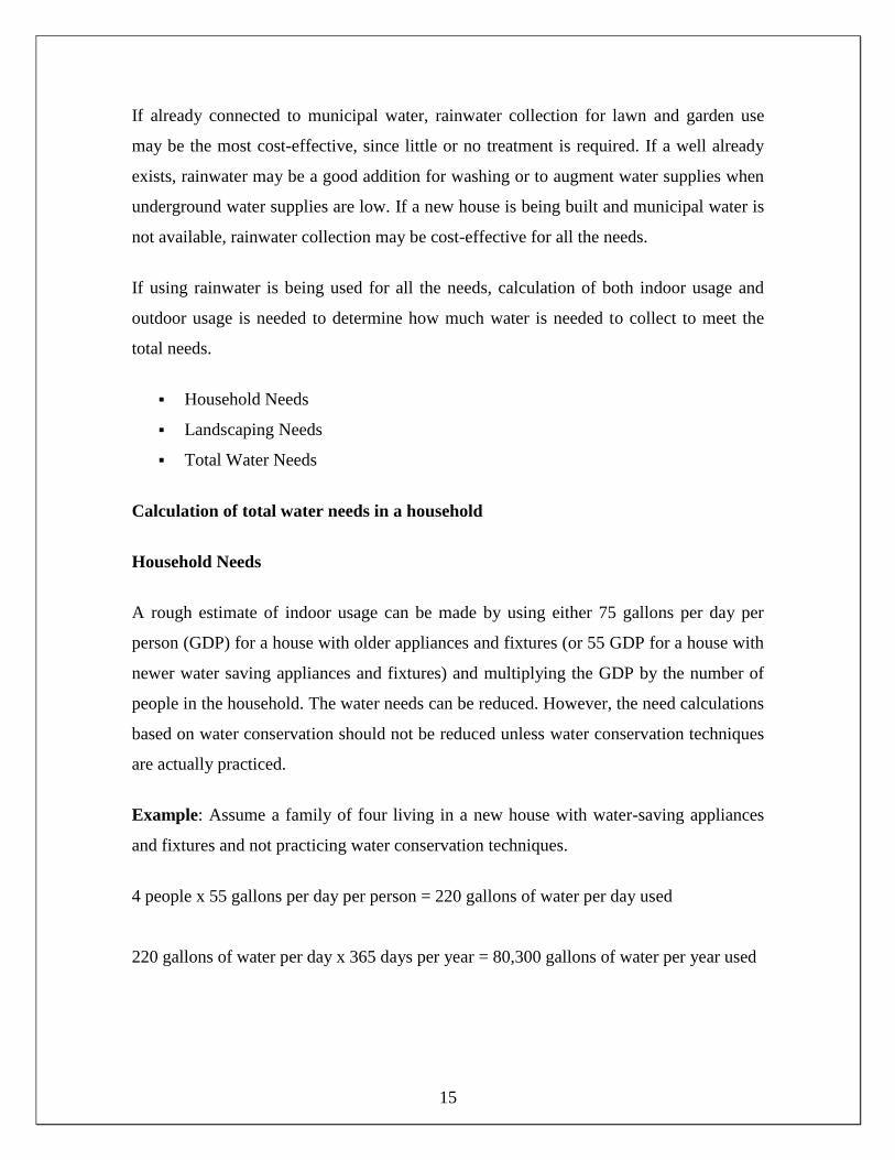
If already connected to municipal water, rainwater collection for lawn and garden use
may be the most cost-effective, since little or no treatment is required. If a well already
exists, rainwater may be a good addition for washing or to augment water supplies when
underground water supplies are low. If a new house is being built and municipal water is
not available, rainwater collection may be cost-effective for all the needs.
If using rainwater is being used for all the needs, calculation of both indoor usage and
outdoor usage is needed to determine how much water is needed to collect to meet the
total needs.
Household Needs
Landscaping Needs
Total Water Needs
Calculation of total water needs in a household
Household Needs
A rough estimate of indoor usage can be made by using either 75 gallons per day per
person (GDP) for a house with older appliances and fixtures (or 55 GDP for a house with
newer water saving appliances and fixtures) and multiplying the GDP by the number of
people in the household. The water needs can be reduced. However, the need calculations
based on water conservation should not be reduced unless water conservation techniques
are actually practiced.
Example: Assume a family of four living in a new house with water-saving appliances
and fixtures and not practicing water conservation techniques.
4 people x 55 gallons per day per person = 220 gallons of water per day used
220 gallons of water per day x 365 days per year = 80,300 gallons of water per year used
16
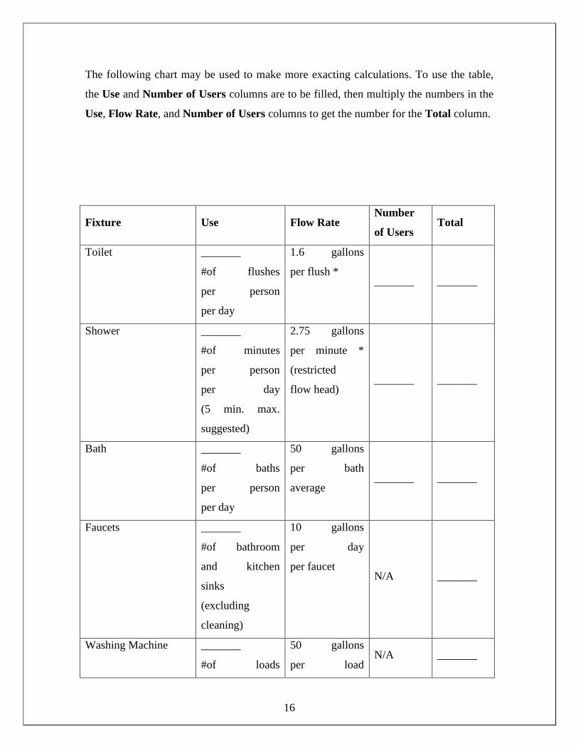
The following chart may be used to make more exacting calculations. To use the table,
the Use and Number of Users columns are to be filled, then multiply the numbers in the
Use, Flow Rate, and Number of Users columns to get the number for the Total column.
Fixture Use Flow Rate Number
of Users Total
Toilet _______
#of flushes
per person
per day
1.6 gallons
per flush * _______ _______
Shower _______
#of minutes
per person
per day
(5 min. max.
suggested)
2.75 gallons
per minute *
(restricted
flow head) _______ _______
Bath _______
#of baths
per person
per day
50 gallons
per bath
average _______ _______
Faucets _______
#of bathroom
and kitchen
sinks
(excluding
cleaning)
10 gallons
per day
per faucet N/A _______
Washing Machine _______
#of loads
50 gallons
per load N/A _______
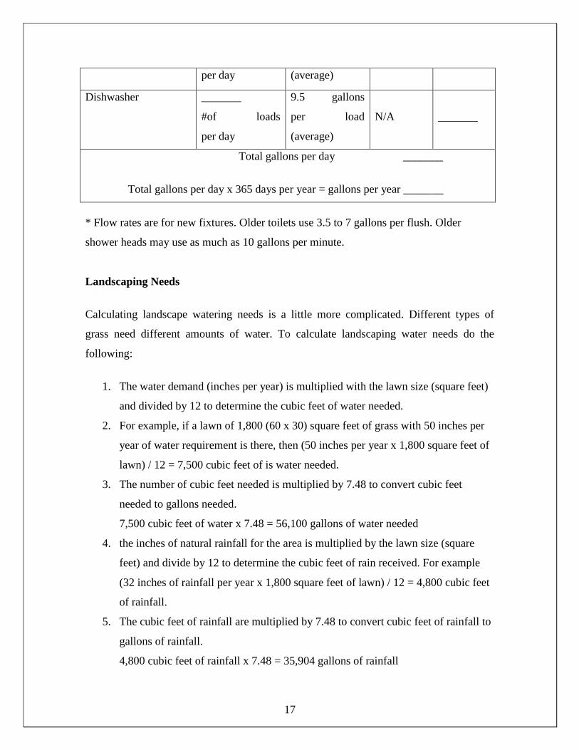
17
per day (average)
Dishwasher _______
#of loads
per day
9.5 gallons
per load
(average)
N/A _______
Total gallons per day _______
Total gallons per day x 365 days per year = gallons per year _______
* Flow rates are for new fixtures. Older toilets use 3.5 to 7 gallons per flush. Older
shower heads may use as much as 10 gallons per minute.
Landscaping Needs
Calculating landscape watering needs is a little more complicated. Different types of
grass need different amounts of water. To calculate landscaping water needs do the
following:
1. The water demand (inches per year) is multiplied with the lawn size (square feet)
and divided by 12 to determine the cubic feet of water needed.
2. For example, if a lawn of 1,800 (60 x 30) square feet of grass with 50 inches per
year of water requirement is there, then (50 inches per year x 1,800 square feet of
lawn) / 12 = 7,500 cubic feet of is water needed.
3. The number of cubic feet needed is multiplied by 7.48 to convert cubic feet
needed to gallons needed.
7,500 cubic feet of water x 7.48 = 56,100 gallons of water needed
4. the inches of natural rainfall for the area is multiplied by the lawn size (square
feet) and divide by 12 to determine the cubic feet of rain received. For example
(32 inches of rainfall per year x 1,800 square feet of lawn) / 12 = 4,800 cubic feet
of rainfall.
5. The cubic feet of rainfall are multiplied by 7.48 to convert cubic feet of rainfall to
gallons of rainfall.
4,800 cubic feet of rainfall x 7.48 = 35,904 gallons of rainfall
18
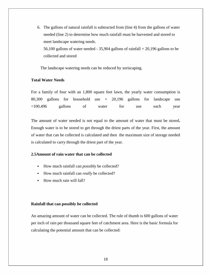
6. The gallons of natural rainfall is subtracted from (line 4) from the gallons of water
needed (line 2) to determine how much rainfall must be harvested and stored to
meet landscape watering needs.
56,100 gallons of water needed - 35,904 gallons of rainfall = 20,196 gallons to be
collected and stored
The landscape watering needs can be reduced by xeriscaping.
Total Water Needs
For a family of four with an 1,800 square feet lawn, the yearly water consumption is
80,300 gallons for household use + 20,196 gallons for landscape use
=100,496 gallons of water for use each year
The amount of water needed is not equal to the amount of water that must be stored.
Enough water is to be stored to get through the driest parts of the year. First, the amount
of water that can be collected is calculated and then the maximum size of storage needed
is calculated to carry through the driest part of the year.
2.5Amount of rain water that can be collected
How much rainfall can possibly be collected?
How much rainfall can really be collected?
How much rain will fall?
Rainfall that can possibly be collected
An amazing amount of water can be collected. The rule of thumb is 600 gallons of water
per inch of rain per thousand square feet of catchment area. Here is the basic formula for
calculating the potential amount that can be collected:
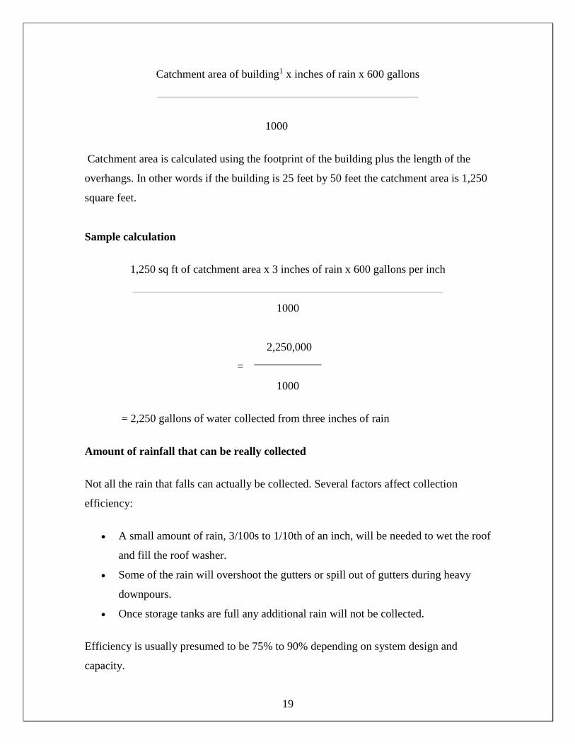
19
Catchment area of building1 x inches of rain x 600 gallons
1000
Catchment area is calculated using the footprint of the building plus the length of the
overhangs. In other words if the building is 25 feet by 50 feet the catchment area is 1,250
square feet.
Sample calculation
1,250 sq ft of catchment area x 3 inches of rain x 600 gallons per inch
1000
2,250,000
=
1000
= 2,250 gallons of water collected from three inches of rain
Amount of rainfall that can be really collected
Not all the rain that falls can actually be collected. Several factors affect collection
efficiency:
A small amount of rain, 3/100s to 1/10th of an inch, will be needed to wet the roof
and fill the roof washer.
Some of the rain will overshoot the gutters or spill out of gutters during heavy
downpours.
Once storage tanks are full any additional rain will not be collected.
Efficiency is usually presumed to be 75% to 90% depending on system design and
capacity.
20
The amount of rain that will fall
How much rain will fall in a given year is unknown. Rainfall data for previous years can
be used to predict how much rain may fall.
The first step in determining reliability of rainfall is to find out the average rainfall in the
area. This may be all that is needed to be known if relying on rainwater as a supplement
to another source.
If rainwater is the sole source of water, the least amount of rainfall in a year and the
period of the year when the rain falls is to be known. If part of the year is very dry, then it
is to be seen if enough water can be collected during the rainy months to last through the
dry months. If only the minimum amount of rain falls in a year, then it is to be known
whether that will be enough to meet needs.
Least Amount of Rainfall
It is important to examine the worst case scenario. A handy rule of thumb to determine
the likelihood of low rainfall is to take the average amount of rainfall for an area and
divide it by two.
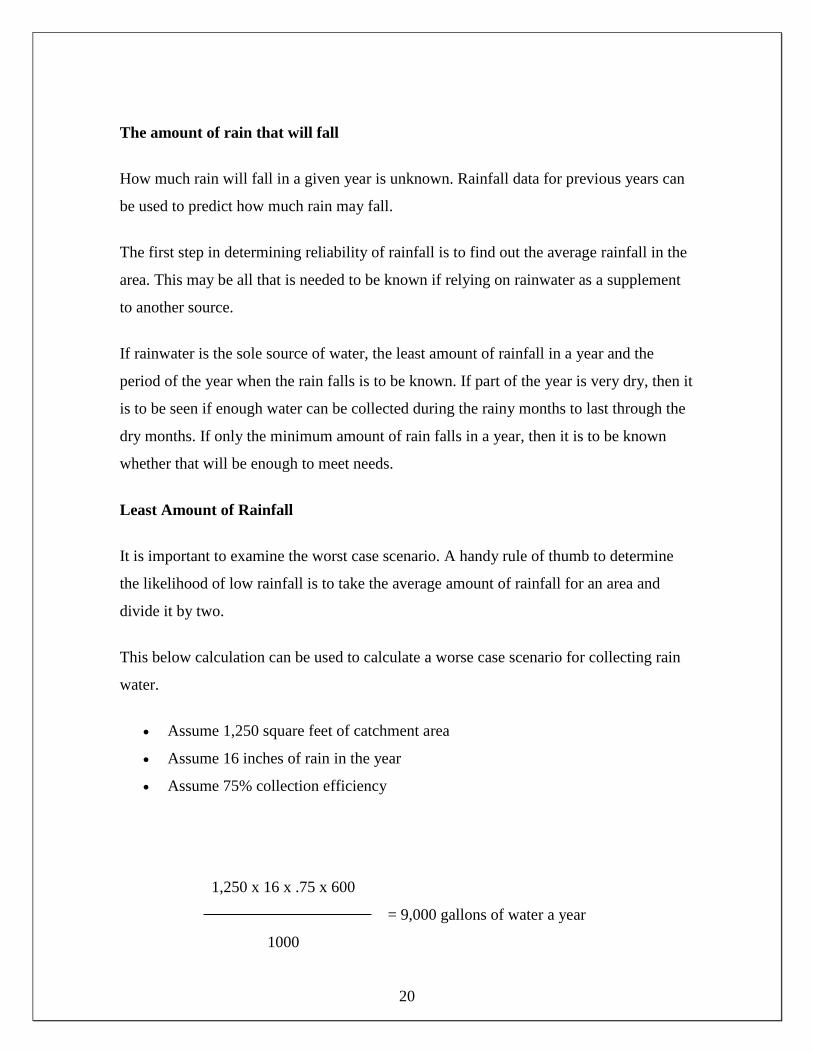
This below calculation can be used to calculate a worse case scenario for collecting rain
water.
Assume 1,250 square feet of catchment area
Assume 16 inches of rain in the year
Assume 75% collection efficiency
1,250 x 16 x .75 x 600
= 9,000 gallons of water a year
1000
21
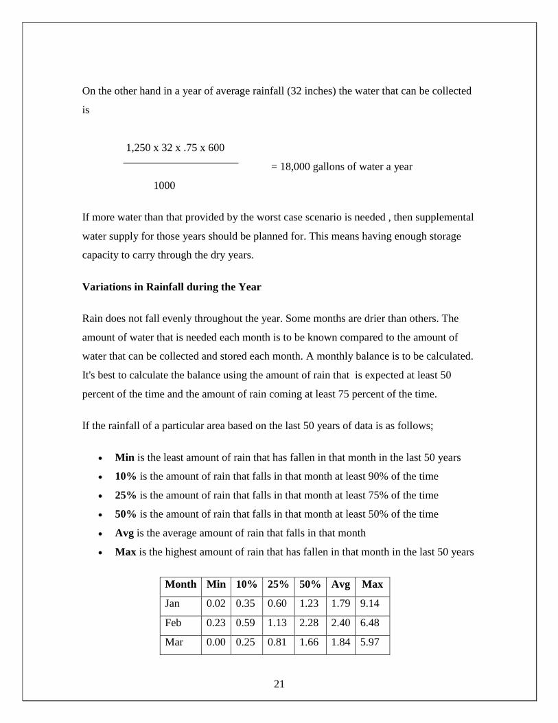
On the other hand in a year of average rainfall (32 inches) the water that can be collected
is
1,250 x 32 x .75 x 600
= 18,000 gallons of water a year
1000
If more water than that provided by the worst case scenario is needed , then supplemental
water supply for those years should be planned for. This means having enough storage
capacity to carry through the dry years.
Variations in Rainfall during the Year
Rain does not fall evenly throughout the year. Some months are drier than others. The
amount of water that is needed each month is to be known compared to the amount of
water that can be collected and stored each month. A monthly balance is to be calculated.
It's best to calculate the balance using the amount of rain that is expected at least 50
percent of the time and the amount of rain coming at least 75 percent of the time.
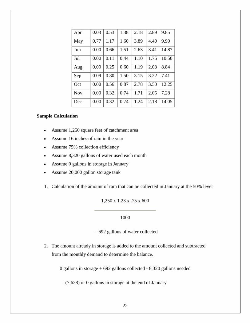
If the rainfall of a particular area based on the last 50 years of data is as follows;
Min is the least amount of rain that has fallen in that month in the last 50 years
10% is the amount of rain that falls in that month at least 90% of the time
25% is the amount of rain that falls in that month at least 75% of the time
50% is the amount of rain that falls in that month at least 50% of the time
Avg is the average amount of rain that falls in that month
Max is the highest amount of rain that has fallen in that month in the last 50 years
Month Min 10% 25% 50% Avg Max
Jan 0.02 0.35 0.60 1.23 1.79 9.14
Feb 0.23 0.59 1.13 2.28 2.40 6.48
Mar 0.00 0.25 0.81 1.66 1.84 5.97
22
Apr 0.03 0.53 1.38 2.18 2.89 9.85
May 0.77 1.17 1.60 3.89 4.40 9.90
Jun 0.00 0.66 1.51 2.63 3.41 14.87
Jul 0.00 0.11 0.44 1.10 1.75 10.50
Aug 0.00 0.25 0.60 1.19 2.03 8.84
Sep 0.09 0.80 1.50 3.15 3.22 7.41
Oct 0.00 0.56 0.87 2.78 3.50 12.25
Nov 0.00 0.32 0.74 1.71 2.05 7.28
Dec 0.00 0.32 0.74 1.24 2.18 14.05
Sample Calculation
Assume 1,250 square feet of catchment area
Assume 16 inches of rain in the year
Assume 75% collection efficiency
Assume 8,320 gallons of water used each month
Assume 0 gallons in storage in January
Assume 20,000 gallon storage tank
1. Calculation of the amount of rain that can be collected in January at the 50% level
1,250 x 1.23 x .75 x 600
1000
= 692 gallons of water collected
2. The amount already in storage is added to the amount collected and subtracted
from the monthly demand to determine the balance.
0 gallons in storage + 692 gallons collected - 8,320 gallons needed
= (7,628) or 0 gallons in storage at the end of January
23
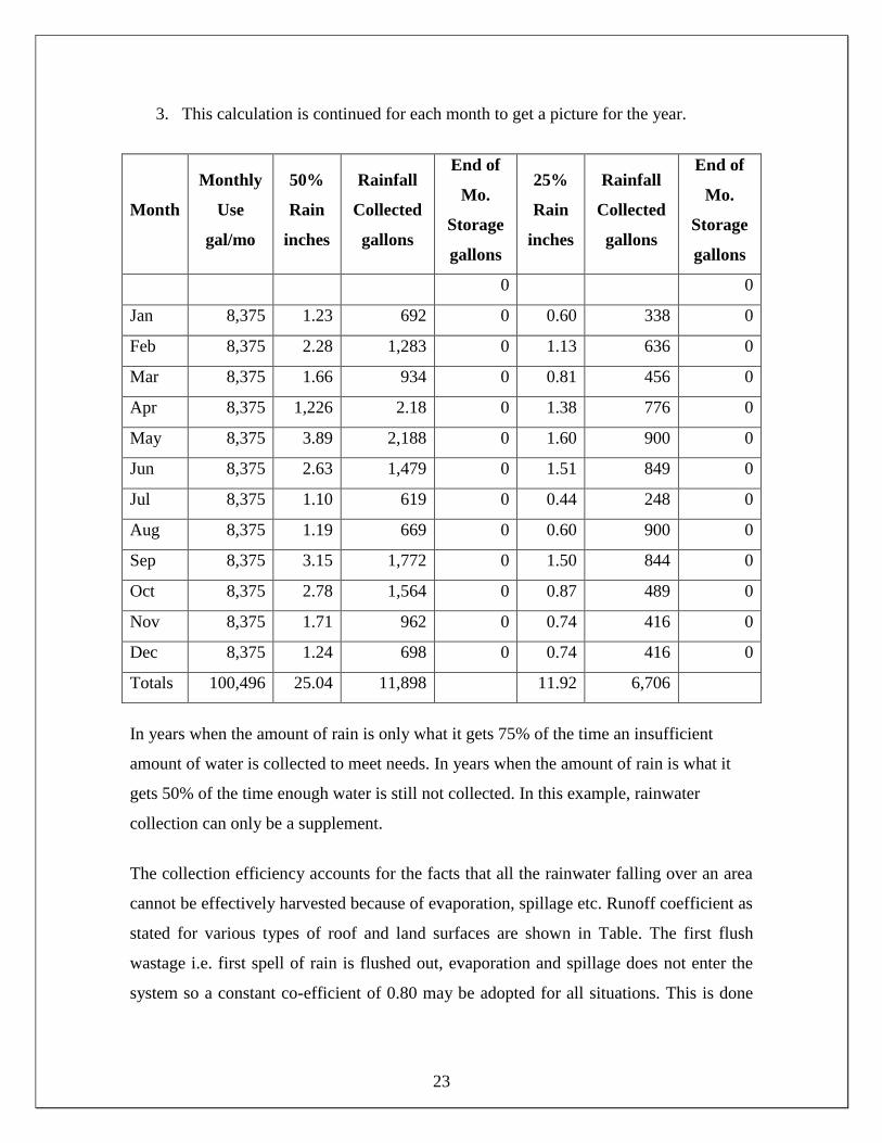
3. This calculation is continued for each month to get a picture for the year.
Month
Monthly
Use
gal/mo
50%
Rain
inches
Rainfall
Collected
gallons
End of
Mo.
Storage
gallons
25%
Rain
inches
Rainfall
Collected
gallons
End of
Mo.
Storage
gallons
0 0
Jan 8,375 1.23 692 0 0.60 338 0
Feb 8,375 2.28 1,283 0 1.13 636 0
Mar 8,375 1.66 934 0 0.81 456 0
Apr 8,375 1,226 2.18 0 1.38 776 0
May 8,375 3.89 2,188 0 1.60 900 0
Jun 8,375 2.63 1,479 0 1.51 849 0
Jul 8,375 1.10 619 0 0.44 248 0
Aug 8,375 1.19 669 0 0.60 900 0
Sep 8,375 3.15 1,772 0 1.50 844 0
Oct 8,375 2.78 1,564 0 0.87 489 0
Nov 8,375 1.71 962 0 0.74 416 0
Dec 8,375 1.24 698 0 0.74 416 0
Totals 100,496 25.04 11,898 11.92 6,706
In years when the amount of rain is only what it gets 75% of the time an insufficient
amount of water is collected to meet needs. In years when the amount of rain is what it
gets 50% of the time enough water is still not collected. In this example, rainwater
collection can only be a supplement.
The collection efficiency accounts for the facts that all the rainwater falling over an area
cannot be effectively harvested because of evaporation, spillage etc. Runoff coefficient as
stated for various types of roof and land surfaces are shown in Table. The first flush
wastage i.e. first spell of rain is flushed out, evaporation and spillage does not enter the
system so a constant co-efficient of 0.80 may be adopted for all situations. This is done
24
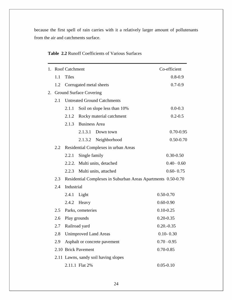
because the first spell of rain carries with it a relatively larger amount of pollutenants
from the air and catchments surface.
Table 2.2 Runoff Coefficients of Various Surfaces
_____________________________________________________________
1. Roof Catchment Co-efficient
1.1 Tiles 0.8-0.9
1.2 Corrugated metal sheets 0.7-0.9
2. Ground Surface Covering
2.1 Untreated Ground Catchments
2.1.1 Soil on slope less than 10% 0.0-0.3
2.1.2 Rocky material catchment 0.2-0.5
2.1.3 Business Area
2.1.3.1 Down town 0.70-0.95
2.1.3.2 Neighborhood 0.50-0.70
2.2 Residential Complexes in urban Areas
2.2.1 Single family 0.30-0.50
2.2.2. Multi units, detached 0.40– 0.60
2.2.3 Multi units, attached 0.60- 0.75
2.3 Residential Complexes in Suburban Areas Apartments 0.50-0.70
2.4 Industrial
2.4.1 Light 0.50-0.70
2.4.2 Heavy 0.60-0.90
2.5 Parks, cemeteries 0.10-0.25
2.6 Play grounds 0.20-0.35
2.7 Railroad yard 0.20.-0.35
2.8 Unimproved Land Areas 0.10- 0.30
2.9 Asphalt or concrete pavement 0.70 –0.95
2.10 Brick Pavement 0.70-0.85
2.11 Lawns, sandy soil having slopes
2.11.1 Flat 2% 0.05-0.10

25
2.11.2 Average 2 to 7% 0.10-0.15
2.11.3 Steep 7% 0.15-0.20
2.12 Lawns, clayey soil having slopes
2.12.1 Flat 2% 0.13- 0.17
2.12.2 Average 2 to 7% 0.18-0.22
2.12.3 Steep 7% 0.25- 0.35
2.13 General Driveways and walls 0.15-0.30
(Source ASCE and WPCF 1969)
Where the use of the runoff coefficients implies there is constant ratio of
rainfall to run off, the actual ratio will vary over the course of a storm due to
condition of the area and at the variability of the rainfall pattern. A common
practice is to use average coefficients for various types of areas and assume
that the coefficients will be constant throughout the duration of the storm.
26
CHAPTER THREE: ROOF TOP RAINWATER HARVESTING
3.1 Introduction
Domestic rainwater harvesting or Rooftop rainwater harvesting is the technique by which
rainwater is captured from roof catchment and is stored in tanks/reservoirs/ ground water
aquifers. It consists of conservation of rooftop rainwater in urban areas and utilizing it to
augment ground water storage by artificial recharge. It requires connecting the out let
pipe from rooftop to divert collected water to existing tank/well/tube well/bore well or a
specially designed well.
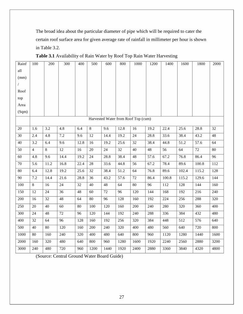
The approximate volume of water available for harvesting with respect to roof top area
and annual rainfall of that area has been shown in Table 3.1 for designing the rainwater
harvesting structures.
Rooftop rainwater harvesting systems, both small and large are comprised of six basic
components as described below:
Catchment Area/ Roof: Surface upon which rainfalls.
Gutters and Down Spouts: Transport channels from catchment surface to storage.
Leaf Screens and Roof Washers: Systems that remove contamination and debris.
Cisterns or Storage Tanks: Where collected rainwater is stored.
Conveying: The delivery system for treated rainwater, either by gravity or pump.
Water treatment: Filters and equipment and additives to settle, filter and disinfect.
The system involves collecting water that falls on the roof (made-up of galvanized iron
sheets/ asbestos sheets or brick tiles) of a house during rain storms, and conveying it by
an Aluminium, PVC wood or plastic drain or collector to a nearby covered storage unit or
cistern. Rainwater yield varies with the size and texture of the catchment area. A
smoother, cleaner and more impervious roofing material contributes to better water
quality and greater quantity.
27
The broad idea about the particular diameter of pipe which will be required to cater the
certain roof surface area for given average rate of rainfall in millimeter per hour is shown
in Table 3.2.
Table 3.1 Availability of Rain Water by Roof Top Rain Water Harvesting
Rainf
all
(mm)
/
Roof
top
Area
(Sqm)
100 200 300 400 500 600 800 1000 1200 1400 1600 1800 2000
Harvested Water from Roof Top (cum)
20 1.6 3.2 4.8 6.4 8 9.6 12.8 16 19.2 22.4 25.6 28.8 32
30 2.4 4.8 7.2 9.6 12 14.4 19.2 24 28.8 33.6 38.4 43.2 48
40 3.2 6.4 9.6 12.8 16 19.2 25.6 32 38.4 44.8 51.2 57.6 64
50 4 8 12 16 20 24 32 40 48 56 64 72 80
60 4.8 9.6 14.4 19.2 24 28.8 38.4 48 57.6 67.2 76.8 86.4 96
70 5.6 11.2 16.8 22.4 28 33.6 44.8 56 67.2 78.4 89.6 100.8 112
80 6.4 12.8 19.2 25.6 32 38.4 51.2 64 76.8 89.6 102.4 115.2 128
90 7.2 14.4 21.6 28.8 36 43.2 57.6 72 86.4 100.8 115.2 129.6 144
100 8 16 24 32 40 48 64 80 96 112 128 144 160
150 12 24 36 48 60 72 96 120 144 168 192 216 240
200 16 32 48 64 80 96 128 160 192 224 256 288 320
250 20 40 60 80 100 120 160 200 240 280 320 360 400
300 24 48 72 96 120 144 192 240 288 336 384 432 480
400 32 64 96 128 160 192 256 320 384 448 512 576 640
500 40 80 120 160 200 240 320 400 480 560 640 720 800
1000 80 160 240 320 400 480 640 800 960 1120 1280 1440 1600
2000 160 320 480 640 800 960 1280 1600 1920 2240 2560 2880 3200
3000 240 480 720 960 1200 1440 1920 2400 2880 3360 3840 4320 4800
(Source: Central Ground Water Board Guide)
28
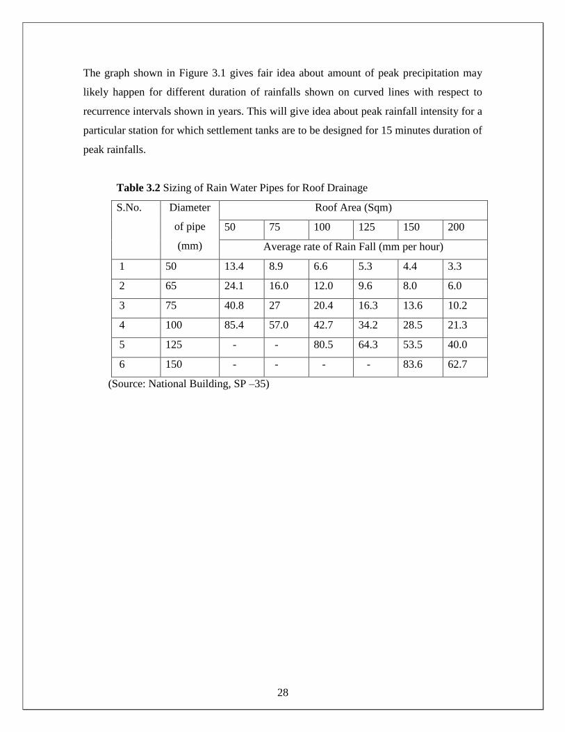
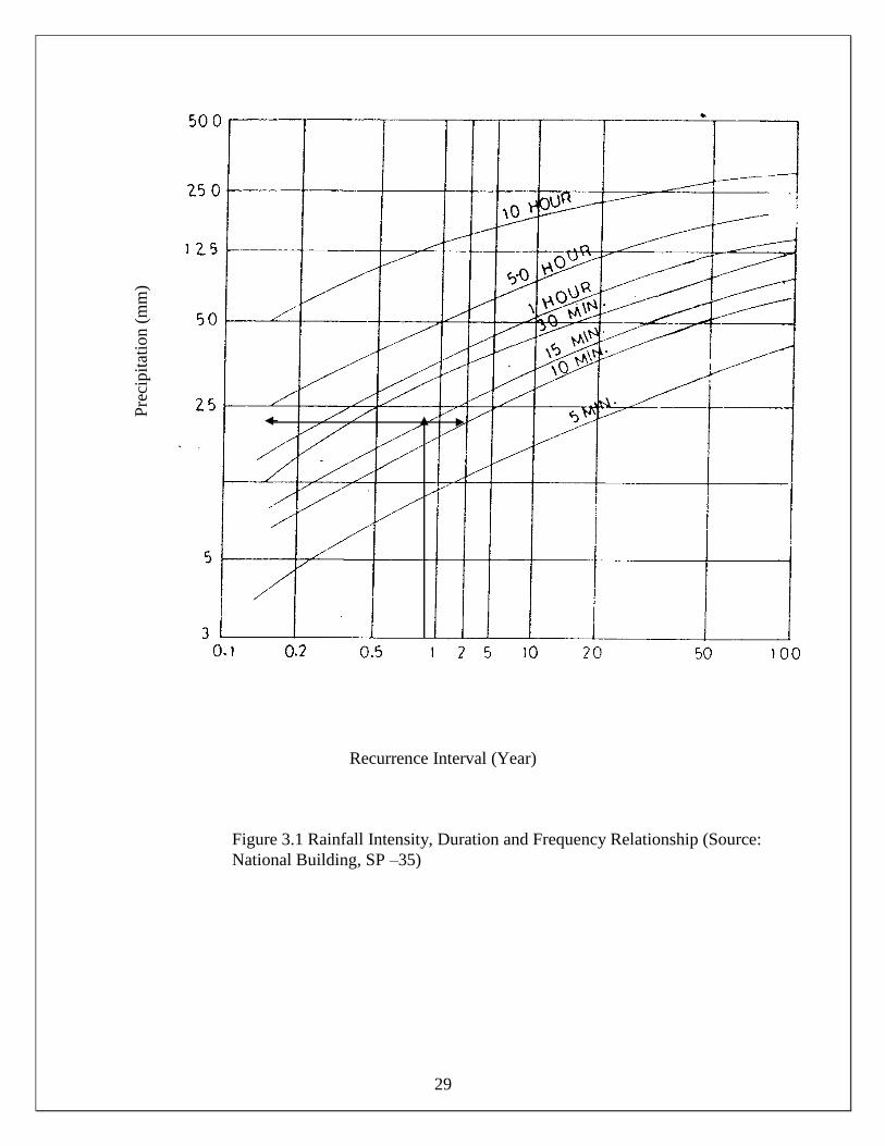
The graph shown in Figure 3.1 gives fair idea about amount of peak precipitation may
likely happen for different duration of rainfalls shown on curved lines with respect to
recurrence intervals shown in years. This will give idea about peak rainfall intensity for a
particular station for which settlement tanks are to be designed for 15 minutes duration of
peak rainfalls.
Table 3.2 Sizing of Rain Water Pipes for Roof Drainage
S.No. Diameter
of pipe
(mm)
Roof Area (Sqm)
50 75 100 125 150 200
Average rate of Rain Fall (mm per hour)
1 50 13.4 8.9 6.6 5.3 4.4 3.3
2 65 24.1 16.0 12.0 9.6 8.0 6.0
3 75 40.8 27 20.4 16.3 13.6 10.2
4 100 85.4 57.0 42.7 34.2 28.5 21.3
5 125 - - 80.5 64.3 53.5 40.0
6 150 - - - - 83.6 62.7
(Source: National Building, SP –35)
29
Pre
cipit
atio
n (
mm
)
Recurrence Interval (Year)
Figure 3.1 Rainfall Intensity, Duration and Frequency Relationship (Source:
National Building, SP –35)
30
3.2Water quality considerations
Primary water quality criteria –health concerns
Once rain comes in contact with a roof or collection surface, it can wash many types of
bacteria, molds, algae, protozoa and other contaminants into the cistern or storage tank.
Indeed, some samples of harvested rainwater have shown detectable levels of these
contaminants. Health concerns related to bacteria, such as salmonella, e-coli and
legionella, and to physical contaminants, such as pesticides, lead, and arsenic, are the
primary criteria for drinking water quality analysis. Falling rain is free of most of these
hazards. Common sense takes a lot of the guess work out of proper treatment procedures.
For example, if the rainwater is intended for use inside the household, either for potable
uses such as drinking and cooking or for non-potable uses including showering and toilet
flushing, appropriate filtration and disinfection practices should be employed. If the
rainwater is to be used outside for landscape irrigation, where human consumption of the
untreated water is less likely, the presence of contaminants may not be of major concern
and thus treatment requirements can be less stringent or not required at all. Depending on
where the system is located, the quality of rainwater itself can vary, reflecting exposure to
air pollution caused by industries such as cement kilns, gravel quarries, crop dusting, and
a high concentration of automobile emissions.
Secondary water quality criteria – aesthetic concerns
Aesthetic concerns such as color, taste, smell, and hardness comprise the secondary
testing criteria used to evaluate publicly supplied water. When assessed according to
these characteristics, rainwater proves to be of better quality than well or municipal tap
water. Inorganic impurities such as suspended particles of sand, clay, and silt contribute
to the water’s color, and smell. Proper screening and removal of sedimentation help to
decrease problems caused by these impurities.
31
Rainwater is the softest natural occurring water available, with a hardness of zero for all
practical purposes. As mentioned above, a benefit of the soft water is that faucets and
water heaters last longer without the build-up of mineral deposits.
Rainwater contains almost no dissolved minerals and salts and is near distilled water
quality. For people on restricted salt diets, this represents a decisive advantage over other
water sources.
The pH of rainfall would be 7.0 if there were nothing else in the air. However, as rain
falls through the air, it dissolves carbon dioxide that is naturally present in the air and
becomes slightly acidic. The resultant pH is 5.6; however, any sulfates or nitrates
dissolved from the air will lower this number below pH 5.6.
Although the pH of rain is below neutral, it is only slightly acidic, and the smallest
amount of buffering can neutralize the acid. The low total dissolved salts and minerals
levels found in rainwater permit even very small amounts of something like baking soda
(one level tablespoon per 100 gallons) to adjust the pH to near neutral.
WATER QUALITY PROPERTIES RELATED TO SPECIFIC USES
Domestic Industrial Irrigation
Taste pH Boron
Odor Acidity Alkalinity
Poisons Alkalinity Sodium-Calcium Ratio
Fluoride Silica Dissolved solids
Nitrate Hardness
Iron Sediment
Hardness Dissolved solids
Sediment
Dissolved solids
32
CHAPTER FOUR: METHODOLOGY OF A RAIN WATER HARVESTING SYSTEM
4.1System components
Whether the system you are planning is large or small, all rainwater harvesting systems
are comprised of six basic components:
Catchment Area/Roof: The surface upon which the rain falls
Gutters and Downspouts: The transport channels from catchment surface to
storage
Leaf Screens and Roof washers: The systems that remove contaminants and
debris
Cisterns or Storage Tanks: Where collected rainwater is stored
Conveying: The delivery system for the treated rainwater, either by gravity or
pump
Water Treatment: Filters and equipment, and additives to settle, filter, and
disinfect
Catchment area
The catchment area is the surface on which the rain that will be collected falls. While in
this text the main focus is on roofs as catchment areas, channeled gullies along
driveways or swales in yards can also serve as catchment areas, collecting and then
directing the rain to a french drain or bermed detention area. Rainwater harvested from
catchment surfaces along the ground, because of the increased risk of contamination,
should only be used for lawn watering. For in-home use, the roofs of buildings are the
primary catchment areas, which, in rural settings, can include outbuildings such as barns
and sheds. A “rainbarn” is a term describing an open-sided shed designed with a large
roof area for catchment, with the cisterns placed inside along with other farm
implements.
33
Rainwater yield varies with the size and texture of the catchment area. A smoother,
cleaner, and more impervious roofing material contributes to better water quality and
greater quantity. While loss is negligible for pitched metal roofs, concrete or asphalt roofs
average just less than 10% loss, and built up tar and gravel roofs average a maximum of
15% loss. Losses can also occur in the gutters and in storage. Regardless of roofing
material, many designers assume up to a 25% loss on annual rainfall. These losses are
due to several factors: the roofing material texture which slows down the flow;
evaporation; and inefficiencies in the collection process.
Type of roofing material
If you are planning a new construction project, metal roofing is the preferred material
because of its smooth surface and durability. Other material options such as clay tile or
slate are also appropriate for rainwater intended to be used as potable water. These
surfaces can be treated with a special painted coating to discourage bacterial growth on
an otherwise porous surface. Because composite asphalt, asbestos, chemically treated
wood shingles and some painted roofs could leach toxic materials into the rainwater as it
touches the roof surface, they are recommended only for non-potable water uses. For
systems intended as potable water sources, no lead is to be used as roof flashing or as
gutter solder as the slightly acid quality of rain can dissolve the lead and thereby
contaminate water supply. Existing houses and buildings should be fully examined for
any lead content in the planning stages of any rainwater collection project.
Catchment area size
The size of a roof catchment area is the building’s footprint under the roof. The
catchment surface is limited to the area of roof which is guttered. To calculate the size of
your catchment area, multiply the length times the width of the guttered area (See
Chapter II for more detail).

34
Gutters and downspouts
These are the components which catch the rain from the roof catchment surface and
transport it to the cistern. Standard shapes and sizes are easily obtained and maintained,
although custom fabricated profiles are also available to maximize the total amount of
harvested rainfall. Gutters and downspouts must be properly sized, sloped, and installed
in order to maximize the quantity of harvested rain.
Materials and sizes
The most common material for off-the-shelf gutters is seamless aluminum, with standard
extrusions of 5 inch and 6 inch sections, in 50 foot lengths. A 3 inch downspout is used
with a 5 inch gutter and a 4 inch downspout is used with a 6 inch gutter. Galvanized
steel is another common material which can be bent to sections larger than 6 inches, in
lengths of 10 feet and 20 feet. A seamless extruded aluminum 6 inch gutter with a 4 inch
downspout can handle about 1,000 square feet of roof area and is recommended for most
cistern installations. For roof areas that exceed 1,000 square feet, larger sections of
gutters and downspouts are commonly fabricated from galvanized steel or the roof area is
divided into several guttered zones. Downspouts are designed to handle 1.25 inches of
rainfall during a 10 minute period.
Copper and stainless steel are also used for gutters and downspouts but at far greater
expense than either aluminum or galvanized steel. Downspouts are typically the same
material as the gutters but of a smaller cross section. The connection between the
downspout to the cistern is generally constructed of Schedule 40 PVC pipe. To keep
leaves and other debris from entering the system, the gutters should have a continuous
leaf screen, made of 1/4 inch wire mesh in a metal frame, installed along their entire
length, and a screen or wire basket at the head of the downspout. Gutter hangers are
generally placed every 3 feet. The outside face of the gutter should be lower than the
inside face to encourage drainage away from the building wall. Where possible, the
gutters should be placed about 1/4 inch below the slope line so that debris can clear
35
without knocking down the gutter. As with the catchment surface, it is important to
ensure that these conduits are free of lead and any other treatment which could
contaminate the water. Check especially if you are retrofitting onto older gutters and
downspouts that may have lead solder or lead-based paint.
Roof washers
Roof washing, or the collection and disposal of the first flush of water from a roof, is of
particular concern if the collected rainwater is to be used for human consumption, since
the first flush picks up most of the dirt, debris, and contaminants, such as bird droppings
that have collected on the roof and in the gutters during dry periods. The most simple of
these systems consists of a stand pipe and a gutter downspout located ahead of the
downspout from the gutter to the cistern. The pipe is usually 6 or 8 inch PVC which has a
valve and clean out at the bottom. Most of these types of roof washers extend from the
gutter to the ground where they are supported. The gutter downspout and top of the pipe
are fitted and sealed so water will not flow out of the top. Once the pipe has filled, the
rest of the water flows to the downspout connected to the cistern. These systems should
be designed so that at least 10 gallons of water are diverted for every 1000 square feet of
collection area. Rather than wasting the water, the first flush can be used for nonpotable
uses such as for lawn or garden irrigation. Several types of commercial roof washers
which also contain filter or strainer boxes are available.
Storage tanks
Other than the roof, which is an assumed cost in most building projects, the storage tank
represents the largest investment in a rainwater harvesting system. To maximize the
efficiency of your system, your building plan should reflect decisions about optimal
placement, capacity, and material selection for the cistern.
36
Siting
Cisterns can be placed both above and below ground. While above ground installations
avoid the costs associated with excavation and certain maintenance issues, cisterns that
are below ground benefit from the cooler year-round ground temperatures. To maximize
efficiency, cisterns should be located as close to both the supply and demand points as
possible. And, to facilitate the use of gravity or lower stress on a pump, the cistern should
be placed on the highest level that is workable.
While the catchment area (roof) should not be shaded by trees, the cistern can benefit
from the shade since direct sunlight can heat the stored rainwater in the tank and thereby
encourage algae and bacterial growth, which can lower water quality. To ensure a safe
water supply, cisterns should be sited at least 50 feet away from sources of pollution such
as animal stables, latrines, or, if the tank is below ground, from septic fields.
Tank placement should also take into consideration the possible need to add water to the
tank from an auxiliary source, such as a water truck, in the event your water supply is
depleted due to over-use or drought conditions. For this reason, the cistern should be
located in a site accessible to a water truck, preferably near a driveway or roadway, and
positioned to avoid crossing over water or sewer lines, lawns or gardens.
Design features
Regardless of the type of tank material you select, the cistern should have a durable,
watertight exterior and a clean, smooth interior, sealed with a non-toxic joint sealant. If
the water is intended for potable use, the tank should be legally approved (food and drug
administration), as should any sealants or paints used inside the tank. A tight-fitting cover
is essential to prevent evaporation, mosquito breeding, and to keep insects, birds, lizards,
frogs and rodents from entering the tank.
37
If the cistern is your only water source, an inflow pipe for an alternate water source is
advisable. All tanks, and especially tanks intended for potable use, should not allow
sunlight to penetrate or algae will grow in the cistern. A settling compartment, which
encourages any roof run-off sediment that may enter the tank to settle rather than be
suspended in the tank, is an option that can be designed into the bottom of the cistern.
Designing a system with two tanks provides some flexibility that may be of value. In
most cases, an additional tank represents added cost, regardless of whether it represents
increased capacity. This is because two smaller tanks of, for example, 1,500 gallons each
are generally more expensive than a single 3,000 gallon tank. The primary benefit of a
multi-tank system is that the system can remain operational if one tank has to be shut
down due to maintenance or leaking.
Regardless of tank type chosen, regular inspection and proper maintenance are imperative
to ensure reliability and safe, efficient operation. Water is heavy. A 500 gallon tank of
water will weigh more than two tons, so a proper foundation and support are essential.
Conveying
Water only flows downhill unless you pump it. The old adage that gravity flow works
only if the tank is higher than the kitchen sink accurately portrays the physics at work.
The water pressure for a gravity system depends on the difference in elevation between
the storage tank and the faucet. Water gains one pound per square inch of pressure for
every 2.31 feet of rise or lift.
Many plumbing fixtures and appliances require 20 psi for proper operation, while
standard municipal water supply pressures are typically in the 40 psi to 60 psi range. To
achieve comparable pressure, a cistern would have to be 92.4 feet (2.31 feet X 40 psi =
92.4 feet) above the home’s highest plumbing fixture. That explains why pumps are
frequently used, much in the way they are used to extract well water.
38
Pumps prefer to push water, not pull it. To approximate the water pressure one would get
from a municipal system, pressure tanks are often installed with the pump. Pressure tanks
have a pressure switch with adjustable settings between 5 and 65 psi. For example, to
keep your in-house pressure at about 35 psi, set the switch to turn off the pump when the
pressure reaches 40 psi and turn it on again when the pressure drops down to 30 psi.
Water treatment
Before making a decision about what type of water treatment method to use, have your
water tested by an approved laboratory and determine whether your water will be used
for potable or non-potable uses.
The types of treatment discussed are filtration, disinfection, and buffering for pH control.
Dirt, rust, scale, silt and other suspended particles, bird and rodent feces, airborne
bacteria and cysts will inadvertently find their way into the cistern or storage tank even
when design features such as roof washers, screens and tight-fitting lids are properly
installed. Water can be unsatisfactory without being unsafe; therefore, filtration and some
form of disinfection is the minimum recommended treatment if the water is to be used for
human consumption (drinking, brushing teeth, or cooking). The types of treatment units
most commonly used by rainwater systems are filters that remove sediment, in consort
with either an ultraviolet light or chemical disinfection.
Filters
Filtration can be as simple as the use of cartridge filters or those used for swimming pools
and hot tubs. In all cases, proper filter operation and maintenance in accordance with the
instruction manual for that specific filter must be followed to ensure safety. Once large
debris is removed by screens and roofwashers, other filters are available which help
improve rainwater quality. Most filters on the market are designed to treat municipal
water or well water. Therefore, filter selection requires careful consideration. Screening,
39
sedimentation, and prefiltering occur between catchment and storage or within the tank.
A cartridge sediment filter, which traps and removes particles of five microns or larger is
the most common filter used for rainwater harvesting.
Sediment filters used in series, referred to as multi-cartridge or in-line filters, sieve the
particles from increasing to decreasing size. These sediment filters are often used as a
pre-filter for other treatment techniques such as ultraviolet light or reverse osmosis filters
which can become clogged from large particles. Unless you are adding something to your
rainwater, there is no need to filter out something that is not present. When a disinfectant
such as chlorine is added to rainwater, an activated carbon filter at the tap may be used to
remove the chlorine prior to use.
Activated carbon filters are subject to becoming sites of bacterial growth. Chemical
disinfectants such as chlorine or iodine must be added to the water prior to the activated
carbon filter. If ultraviolet light or ozone is used for disinfection, the system should be
placed after the activated carbon filter. Many water treatment standards require some type
of disinfection after filtration with activated carbon. Ultraviolet light disinfection is often
the method of choice. All filters must be replaced per recommended schedule rather than
when they cease to work; failure to do so may result in the filter contributing to the
water’s contamination.
Disinfection
Ultraviolet Light (UV) water disinfection, a physical process, kills most microbiological
organisms that pass through them. Since particulates offer a hiding place for bacteria and
microorganisms, prefiltering is necessary for UV systems. To determine whether the
minimum dosage is distributed throughout the disinfection chamber, UV water treatment
units should be equipped with a light sensor. Either an alarm or shut-off switch is
activated when the water does not receive the adequate level of UV radiation. The UV
unit must be correctly calibrated and tested after installation to insure that the water is
40
being disinfected. Featured in the case studies are several systems which utilize
ultraviolet light.
Ozone. Ozone is a form of oxygen (03) produced by passing air through a strong electric
field. Ozone readily kills microorganisms and oxidizes organic matter in the water into
carbon dioxide and water. Any remaining ozone reverts back to dissolved oxygen (02) in
the water. Recent developments have produced compact ozone units for home use. Since
ozone is produced by equipment at the point of use with electricity as the only input,
many rainwater catchment systems owners use it to avoid having to handle chlorine or
other chemicals. Ozone can also be used to keep the water in cisterns "fresh". When used
as the final disinfectant, it should be added prior to the tap, but after an activated carbon
filter, if such a filter is used.
Chlorine or iodine for disinfecting. Private systems do not disinfect to the extent of
public water systems where the threat of a pathogenic organism such as e.coli can affect
many households. If the harvested rainwater is used to wash clothes, water plants, or
other tasks that do not involve direct human consumption or contact, treatment beyond
screening and sedimentation removal is optional. However, if the water is plumbed into
the house for general indoor use such as for drinking, bathing, and cooking, disinfection
is needed.
Chlorine is the most common disinfectant because of its dependability, water solubility,
and availability. Granular or tablet form is available (calcium hypochlorite), but the
recommended application for rainwater disinfecting is in a liquid solution (sodium
hypochlorite). Household bleach contains a 5.0% solution of sodium hypochlorite, and is
proven to be reliable, inexpensive and easily obtained. A dose is one liquid ounce of
bleach for each 100 gallons (one and a quarter cups of bleach per 1,000 gallons) of
rainwater collected will most likely be sufficient to disinfect the collected rainwater.
When disinfecting, never overdose with bleach. Mixing occurs naturally over a day or
so, but a clean paddle may be used to accelerate the process. When chlorine bleach is
41
added directly to the storage tank or cistern as described above, the chlorine will have a
longer time to kill bacteria thus achieving a better rate of disinfection.
Chlorine feed pumps which release small amounts of solution while the water is being
pumped can also be used. Chlorine metering pumps inject chlorine into the water only at
the time of use. Chlorine concentrations are easily measured with a swimming pool test
kit. A level of between 0.2 mg/L (milligrams per liter) and 1.5 mg/L is recommended. If
the level is below 0.2 mg/L, add one liquid ounce of chlorine bleach per 100 gallons of
the volume of water in storage (one and a quarter cups per 1,000 gallons) if you are using
bleach or adjust the chemical feed pump in accordance with the pump’s instructions.
Testing should occur outside the tank. Chlorine is more effective at higher water
temperatures and lower pH levels than iodine. Iodine is another water disinfectant that is
less soluble than chlorine although it is effective over a pH range of 5 to 9 and displays
greater antibacterial activity in water temperatures of 75 to 98.6 degrees Fahrenheit.
Prolonged presence of chlorine where organic matter may be present may cause the
formation of chlorinated organic compounds. If chlorine is used as a disinfectant,
all organic material from the tank should be screened.
Buffering
Baking soda for buffering. The composition and pH of rainwater differs from chemically
treated municipal water and mineral rich well water. Controlling the pH of rainwater by
buffering can be easily accomplished by adding one level tablespoon of baking soda to
the storage tank for each 100 gallons of water collected. (About four ounces by weight of
baking soda for every 1,000 gallons of water collected.) An easy method is to mix this
amount of baking soda in a jar of water and pour it into the tank. Mixing will occur
naturally over a day or two or a clean paddle may be used to hasten the process, but avoid
disturbing materials that have settled at the bottom of the cistern.
42
CHAPTER FIVE: DESIGN OF STORAGE, SETTLEMENT TANKS AND RECHAGE
STRUCTUTES
5.1Design of Storage Tanks
The quantity of water stored in a water harvesting system depends on size of the
catchment area and the size of the storage tanks. The storage tank has to be
designed according to the water requirements, rainfall and catchment availability.
Basic Data
i. Average annual rainfall
ii. Size of catchments
iii. Drinking water requirements
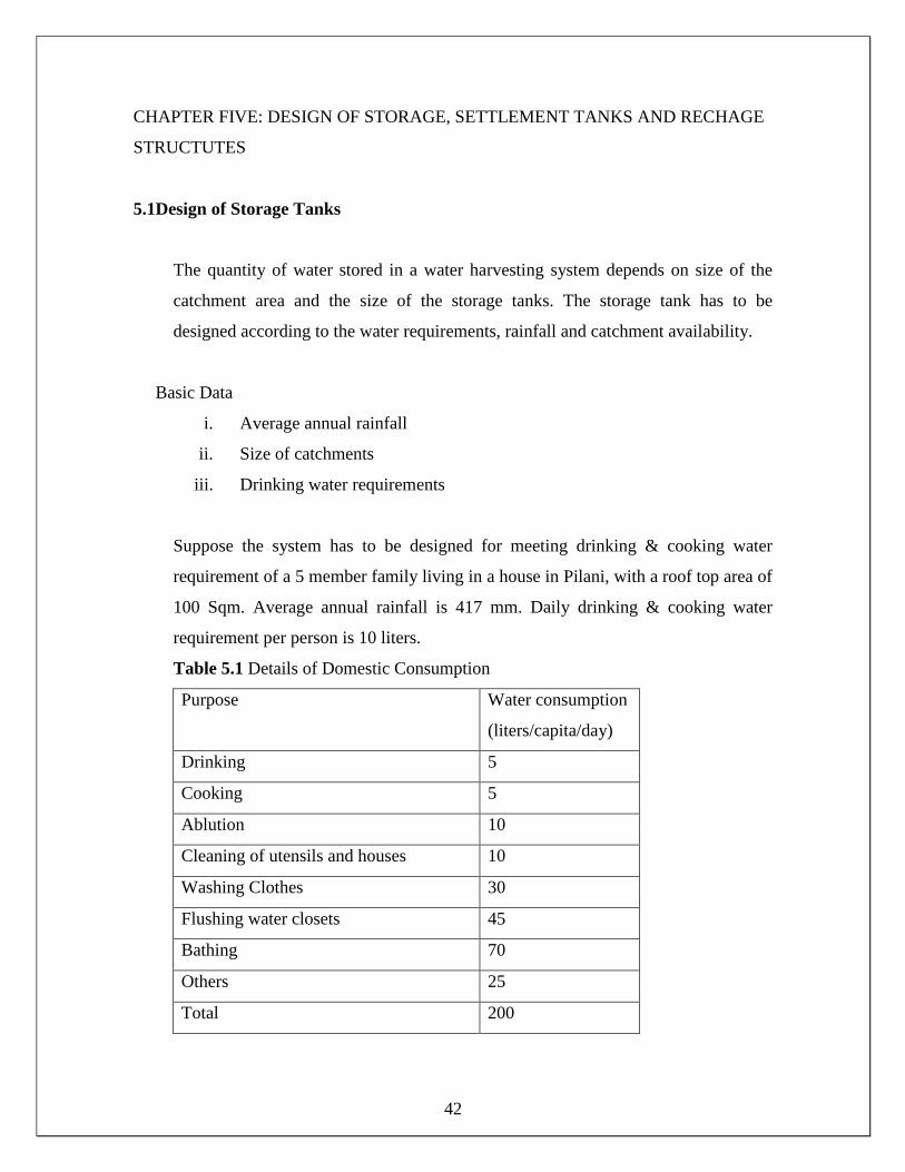
Suppose the system has to be designed for meeting drinking & cooking water
requirement of a 5 member family living in a house in Pilani, with a roof top area of
100 Sqm. Average annual rainfall is 417 mm. Daily drinking & cooking water
requirement per person is 10 liters.
Table 5.1 Details of Domestic Consumption
Purpose Water consumption
(liters/capita/day)
Drinking 5
Cooking 5
Ablution 10
Cleaning of utensils and houses 10
Washing Clothes 30
Flushing water closets 45
Bathing 70
Others 25
Total 200
43
(Source: Code of Basic Requirements for Water Supply, Drainage and Sanitation,
Is: 1172, 1983)
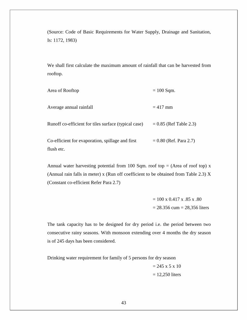
We shall first calculate the maximum amount of rainfall that can be harvested from
rooftop.
Area of Rooftop = 100 Sqm.
Average annual rainfall = 417 mm
Runoff co-efficient for tiles surface (typical case) = 0.85 (Ref Table 2.3)
Co-efficient for evaporation, spillage and first = 0.80 (Ref. Para 2.7)
flush etc.
Annual water harvesting potential from 100 Sqm. roof top = (Area of roof top) x
(Annual rain falls in meter) x (Run off coefficient to be obtained from Table 2.3) X
(Constant co-efficient Refer Para 2.7)
= 100 x 0.417 x .85 x .80
= 28.356 cum = 28,356 liters
The tank capacity has to be designed for dry period i.e. the period between two
consecutive rainy seasons. With monsoon extending over 4 months the dry season
is of 245 days has been considered.
Drinking water requirement for family of 5 persons for dry season
= 245 x 5 x 10
= 12,250 liters
44
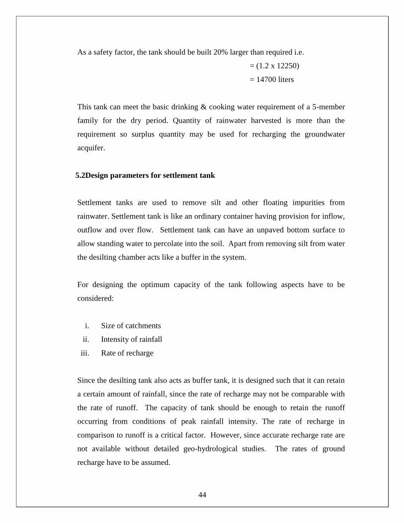
As a safety factor, the tank should be built 20% larger than required i.e.
= (1.2 x 12250)
= 14700 liters
This tank can meet the basic drinking & cooking water requirement of a 5-member
family for the dry period. Quantity of rainwater harvested is more than the
requirement so surplus quantity may be used for recharging the groundwater
acquifer.
5.2Design parameters for settlement tank
Settlement tanks are used to remove silt and other floating impurities from
rainwater. Settlement tank is like an ordinary container having provision for inflow,
outflow and over flow. Settlement tank can have an unpaved bottom surface to
allow standing water to percolate into the soil. Apart from removing silt from water
the desilting chamber acts like a buffer in the system.
For designing the optimum capacity of the tank following aspects have to be
considered:
i. Size of catchments
ii. Intensity of rainfall
iii. Rate of recharge
Since the desilting tank also acts as buffer tank, it is designed such that it can retain
a certain amount of rainfall, since the rate of recharge may not be comparable with
the rate of runoff. The capacity of tank should be enough to retain the runoff
occurring from conditions of peak rainfall intensity. The rate of recharge in
comparison to runoff is a critical factor. However, since accurate recharge rate are
not available without detailed geo-hydrological studies. The rates of ground
recharge have to be assumed.
45
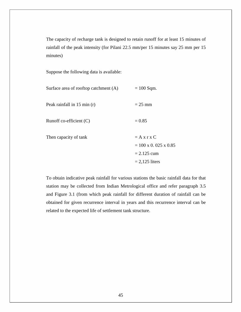
The capacity of recharge tank is designed to retain runoff for at least 15 minutes of
rainfall of the peak intensity (for Pilani 22.5 mm/per 15 minutes say 25 mm per 15
minutes)
Suppose the following data is available:
Surface area of rooftop catchment (A) = 100 Sqm.
Peak rainfall in 15 min (r) = 25 mm
Runoff co-efficient (C) = 0.85
Then capacity of tank = A x r x C
= 100 x 0. 025 x 0.85
= 2.125 cum
= 2,125 liters
To obtain indicative peak rainfall for various stations the basic rainfall data for that
station may be collected from Indian Metrological office and refer paragraph 3.5
and Figure 3.1 (from which peak rainfall for different duration of rainfall can be
obtained for given recurrence interval in years and this recurrence interval can be
related to the expected life of settlement tank structure.
46
5.3Design of recharge structures
Recharge Structures
In places where the withdrawal of water is more than the rate of recharge an
imbalance in the groundwater reserves is created. Recharging of aquifers is
undertaken with the following objectives:
To maintain or augment natural groundwater as an economic resource.
To conserve excess surface water underground.
To combat progressive depletion of groundwater levels.
To combat unfavorable salt balance and saline water intrusion.
To achieve the objectives it is imperative to plan out an artificial recharge scheme
in a scientific manner. Thus it is imperative that proper scientific investigations be
carried out for selection of site for artificial recharge of groundwater.
Detailed knowledge of geological and hydrological features of the area is necessary
for adequately selecting the site and type of recharge structure. In particular, the
features parameters and data to be considered are; geological boundaries,
hydrological boundaries, inflow of water, storage capacity, porosity, hydraulic
conductivity, transmissivity, natural discharge of springs, water resources available
for recharge, natural recharge, water balance litho logy, depth of aquifer, tectonic
boundaries. The aquifers best suited for artificial recharge are those aquifers, which
absorb large quantity of water and do not release the same too quickly.
47
The proper design will include the following considerations
Selection of site
Recharge structures should be planned out after conducting proper hydro-geological
investigations. Based on the analysis of this data (already existing or those collected during
investigation) it should be possible to:
Define the sub-surface geology.
Determine the presence or absence of impermeable layers or lenses that can
impede percolation.
Define depths to water table and groundwater flow directions.
Establish the maximum rate of recharge that could be achieved at the site.
Source of water used for recharge
Basically the potential of rainwater harvesting, quantity and quality of water
available for recharging, have to be assessed.
Engineering, construction and costs
Sound engineering and construction practices are exercised so that construction
costs are affordable and projects are economical viable.
Operation, maintenance and monitoring
The rainwater harvesting structures should be replicable and sustainable. These
should be free from maintenance as far as possible. Also these should be easy to
maintain and operate. There should be arrangements for monitoring the elements
of the whole system including the ground water table levels.
48
Types of Recharge Structures
Recharge through abandoned Dug Well
Recharge through abandoned/running Hand Pump
Recharge through Trench
Recharge through gravity head Recharge Well
Recharge through Shaft
Abandoned Dug Well
A dry or unused dug well can be used as a recharge structure.
The recharge water is guided through a pipe to the bottom of well or below the
water level to avoid scouring of bottom and entrapment of air bubbles in the
aquifer.
Before using the dug well as recharge structure, its bottom should be cleaned and
all the fine deposits should be removed.
Recharge water should be silt free as far as possible.
It should be cleaned annually preferably.
It is suitable for large building having the roof area more than 1000 Sqm.
The run off of first rain should not be allowed to go percolate to the rain water
harvesting structure and is allowed to go to the drain by making suitable by-pass
arrangement in water carrying pipe systems.
Abandoned/Running Hand Pump
An abandoned / running hand pump can be used for recharge.
The structures are suitable for the small building having the roof area up to 150
Sqm.
Water is diverted from rooftop to the hand pump through pipe of diameter 50 to
100 mm.
49
For running hand pump a closing valve is fitted in conveyance system near hand
pump to avoid entry of air in the suction pipe.
Recharge water should be silt free.
The run off of first rain should not be allowed to go percolate to the rain water
harvesting structure and is allowed to go to the drain by making suitable by-pass
arrangement in water carrying pipe systems.
Recharge Trench
It is constructed when a permeable stratum of adequate thickness is available at
shallow depth.
It is a trench of shallow depth filled with pebbles and boulders.
These are constructed across the land slope.
The trench may be 0.5 to 1 m wide 1 to 1.5 m deep and 10 to 20 m long
depending upon the availability of land and roof top area.
It is suitable for the buildings having the roof area of 200 to 300 Sqm.
Cleaning of trench should be done periodically.
Gravity Head Recharge Well
Bore wells/tube wells can be used as recharge structures.
This technique is suitable where
o Land availability is Limited
o When aquifer is deep and over laid by impermeable strata
The rooftop rainwater is conveyed to the well and recharged under gravity flow
condition.
Recharge water should be silt free as far as possible.
The well can also be used for pumping.
Most suitable for the areas where ground Water levels are deep
50
The number of recharging structures can be determined in limited area around
the buildings depending upon roof top area and aquifer characteristics.
The runoff of first rain should not be allowed to go percolate to the rain water
harvesting structures and is allowed to go to the drain by making suitable by-pass
arrangement in water carrying pipe systems.
Recharge Shaft
A recharge shaft is dug manually or drilled by the reverse/direct rotary method.
Diameter of recharge shaft varies from 0.5 to 3 m depending upon the availability
of water to be recharged.
It is constructed where the shallow aquifer is located below clayey surface.
Recharge shaft is back filled with boulders, gravels and coarse sand.
It should end in more permeable strata (sand).
Depth of recharge shaft varies from 10 – 15 m below ground level.
Recharge shaft should be constructed 10 to 15 m away from buildings for the
safety of building.
It should be cleaned annually preferably by scraping the top layer of sand and
refilling it accordingly.
Maintenance of Recharge Structures
Roof Top Rain Water Harvesting for ground water recharge involves injection of
rainwater into the aquifer through recharge trench cum tube wells under gravity
flow. The surface water although treated through the filter bed may cause
clogging after comparatively short periods of injection. In this case though the
precaution is taken, there is a probability of silt being injected into the recharge
wells and may cause clogging. Short periods of pumping quickly remove the
clogging particles and improve the recharge capacity. Annual redevelopment of
recharge wells by air compressor is recommended for improving the recharge
capacity of trench cum recharge wells. Moreover silt deposited on sand bed also
51
reduces the recharge rate. This also needs periodic removal of the finer material
by scraping.
Selection of Recharge Structure
The types of Recharge structures to be considered for different areas (Alluvial
areas or Hard Rock areas) for various roofs are shown in Table 5.1.
The Whole complex/colony can be suitably divided in various clusters and one of
the above systems appropriate to the roof size and underground characteristics
may be selected for use.
General Recommendations for Rain Water Harvesting
Guidelines for action plan for artificial recharge project.
Collect basic data on topography, rainfall pattern of that area, hydrogeology
aquifer situation, and land-source water availability. Identify the methods, which
are most suitable.
With reference to the local conditions of the area further identify the most
appropriate techniques of artificial recharge suitable at various sites/ locations on
the basis of total available volume of rainwater that can be harvested and the
location of available aquifer. Whether it is at shallow depths i.e. 6 to 8 meters
from ground level or at sufficient depths i.e. more than 8 meters from ground
level.
Determine the number of each type of artificial recharge structure needed to
achieve the quantitative targets. The recharge structure should be designed with
volume of water it may store for equivalent of 24 hours rainfall and surface area
of run-off for which the recharge structure has been considered, without giving
any allowance for percolation during this period of 24 hours.
52
For individual structure at different locations, finalize the design the design
specifications from the details given in case studies. If required, the necessary
advice from local Geological Department or Central Ground Water Board may be
obtained.
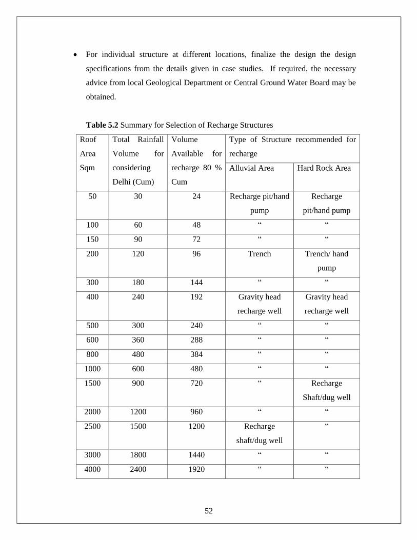
Table 5.2 Summary for Selection of Recharge Structures
Roof
Area
Sqm
Total Rainfall
Volume for
considering
Delhi (Cum)
Volume
Available for
recharge 80 %
Cum
Type of Structure recommended for
recharge
Alluvial Area Hard Rock Area
50 30 24 Recharge pit/hand
pump
Recharge
pit/hand pump
100 60 48 “ “
150 90 72 “ “
200 120 96 Trench Trench/ hand
pump
300 180 144 “ “
400 240 192 Gravity head
recharge well
Gravity head
recharge well
500 300 240 “ “
600 360 288 “ “
800 480 384 “ “
1000 600 480 “ “
1500 900 720 “ Recharge
Shaft/dug well
2000 1200 960 “ “
2500 1500 1200 Recharge
shaft/dug well
“
3000 1800 1440 “ “
4000 2400 1920 “ “
53
5000 3000 2400 “ “
(Source: Central Ground Water Board)
Finalize the design of the conveyance system required to bring the source water to
the recharge structure site and the treatment required in the form of settlement
tanks.
Plan the required monitoring system to evaluate the efficiency of recharge scheme
and ensure regular maintenance of recharge structures before onset of monsoon
every year.
In a given plot attempt should be made to keep the maximum plot area as katcha area
which allows rainwater for percolation to ground water.
The rainwater from season’s first rain should normally not be used for percolation to
recharge structure because it contains pollutants from the air and catchment surface. For
such water suitable arrangement for by pass in pipe system should be introduced.
A suitable provision should be made if possible to allow rain water to percolate to ground
water after passing it through settlement tank because such rain water contains silt which is
deposited on sand bed and reduces the percolation rates.
The recharge structure should be made on a plot at the places of lower levels elevations so
that rainwater may flow towards it under normal gravitation flow.
On a vast and sloppy land patch, the contour bunds preferably of mud with height varying
from 15 cm to 30 cm should be made to store run off temporarily over the katcha land area,
thus allowing more time for percolation of water to the ground water and arresting the flow
of run off to the drains / sewers.
For recharge of run off from roads suitable arrangements in the footpath by introducing
some katcha area should be made.
54
In large residential and office complexes the drive ways, pucca path and areas should hand
some katcha area which may facilitate rain water to percolate to ground water.
Ideal conditions for rain water harvesting and artificial recharge to ground water artificial
recharge techniques are adopted where:
Adequate space for surface storage is not available specially in urban areas.
Water level is deep enough (more than 8 mtr) and adequate sub-surface storage is
available.
Permeable strata are available at shallow/ moderate depth up to 10 to 15 mtr.
Where adequate quality of surface water is available for recharge to ground water.
Ground water quality is bad and our aim is to improve it.
Where there is possibility of intrusion of saline water especially in coastal area.
Where the evaporation rate is very high from surface water bodies.
The decision whether to store or recharge rain water depends on the rainfall pattern of a
particular region.
If the rain fall period between two spells of the rain is short i.e. two to four month,
in such situation a small domestic size water tank for, storing rain water for
drinking and cooking purpose can be used.
In other regions where total annual rain fall occurs only during 3 to 4 months of
monsoon and the period between two such spells is very large i.e. 7 to 8 months,
so it is feasible to use rain water to percolate to the ground water aquifers rather
than for storage which means that huge volumes of storage container are required.
55
CHAPTER SIX: CASE STUDIES
Rainwater Harvesting and Well Replenishing project at Raila
This case study shows the Rainwater Harvesting and Well Replenishing (RHWR)
project at Raila Village 5 km from campus of BITS, Pilani. In fact it will build a
network of water storage clusters. A cluster may consist of several tanks attached to a
group of houses. In turn, these clusters will be connected to a community tank. The
proposed scheme presented for rainwater harvesting is based on four types of rain water
collection tanks. Let us denote the tanks by A, B, C and D. Storage capacity and over
flow from each type of tank is shown in Table 6.1. Surplus water from each type of
tanks will be overflowed to the next type of tank and at last to the community tank from
where it will recharge the groundwater. These are shown in Figure 6.1. To find the
capacity of various tanks, calculation (Table 6.1) were carried out to meet the desired
capacities, requirements and supply at different locations.
Proposed scheme
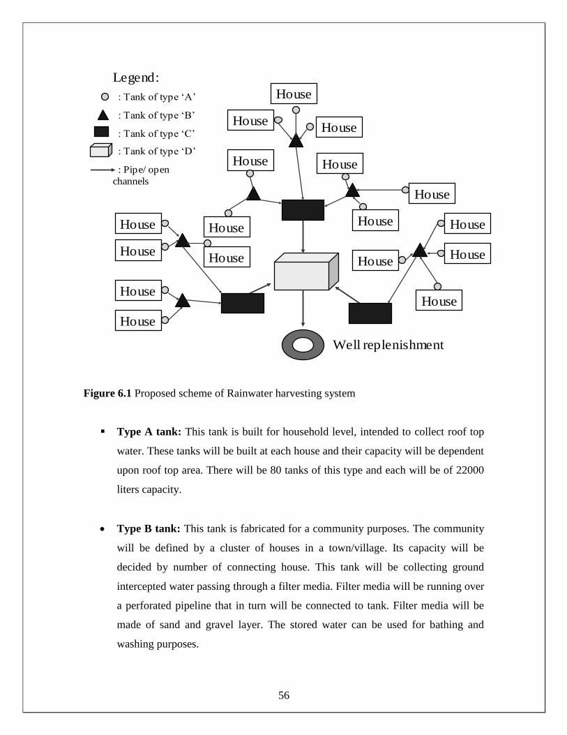
56
House
House
House
House
House
House
House
House
House
House
House
House
House
House
House
House
House
Legend:
: Tank of type ‘A’
: Tank of type ‘B’
: Tank of type ‘C’
: Tank of type ‘D’
: Pipe/ open
channels
Well replenishment
Figure 6.1 Proposed scheme of Rainwater harvesting system
Type A tank: This tank is built for household level, intended to collect roof top
water. These tanks will be built at each house and their capacity will be dependent
upon roof top area. There will be 80 tanks of this type and each will be of 22000
liters capacity.
Type B tank: This tank is fabricated for a community purposes. The community
will be defined by a cluster of houses in a town/village. Its capacity will be
decided by number of connecting house. This tank will be collecting ground
intercepted water passing through a filter media. Filter media will be running over
a perforated pipeline that in turn will be connected to tank. Filter media will be
made of sand and gravel layer. The stored water can be used for bathing and
washing purposes.
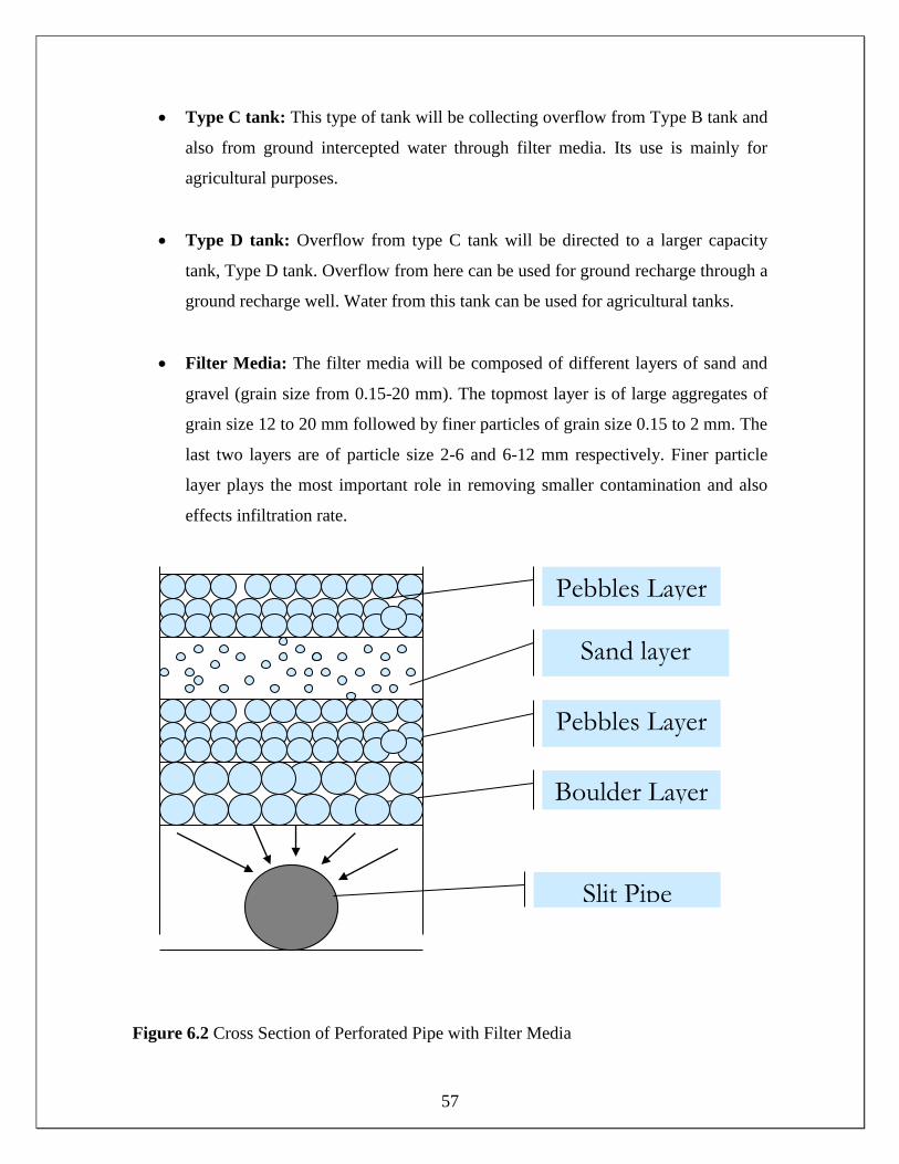
57
Type C tank: This type of tank will be collecting overflow from Type B tank and
also from ground intercepted water through filter media. Its use is mainly for
agricultural purposes.
Type D tank: Overflow from type C tank will be directed to a larger capacity
tank, Type D tank. Overflow from here can be used for ground recharge through a
ground recharge well. Water from this tank can be used for agricultural tanks.
Filter Media: The filter media will be composed of different layers of sand and
gravel (grain size from 0.15-20 mm). The topmost layer is of large aggregates of
grain size 12 to 20 mm followed by finer particles of grain size 0.15 to 2 mm. The
last two layers are of particle size 2-6 and 6-12 mm respectively. Finer particle
layer plays the most important role in removing smaller contamination and also
effects infiltration rate.
Figure 6.2 Cross Section of Perforated Pipe with Filter Media
Slit Pipe
Boulder Layer
Pebbles Layer
Sand layer
Pebbles Layer
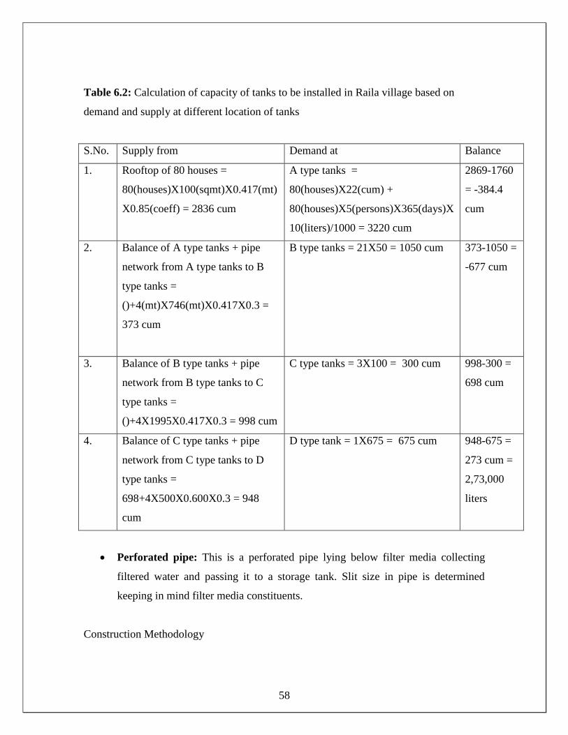
58
Table 6.2: Calculation of capacity of tanks to be installed in Raila village based on
demand and supply at different location of tanks
S.No. Supply from Demand at Balance
1. Rooftop of 80 houses =
80(houses)X100(sqmt)X0.417(mt)
X0.85(coeff) = 2836 cum
A type tanks =
80(houses)X22(cum) +
80(houses)X5(persons)X365(days)X
10(liters)/1000 = 3220 cum
2869-1760
= -384.4
cum
2. Balance of A type tanks + pipe
network from A type tanks to B
type tanks =
()+4(mt)X746(mt)X0.417X0.3 =
373 cum
B type tanks = 21X50 = 1050 cum 373-1050 =
-677 cum
3. Balance of B type tanks + pipe
network from B type tanks to C
type tanks =
()+4X1995X0.417X0.3 = 998 cum
C type tanks = 3X100 = 300 cum 998-300 =
698 cum
4. Balance of C type tanks + pipe
network from C type tanks to D
type tanks =
698+4X500X0.600X0.3 = 948
cum
D type tank = 1X675 = 675 cum 948-675 =
273 cum =
2,73,000
liters
Perforated pipe: This is a perforated pipe lying below filter media collecting
filtered water and passing it to a storage tank. Slit size in pipe is determined
keeping in mind filter media constituents.
Construction Methodology
59
Simple construction technology is suitable for rainwater harvesting projects. The
type of technology and materials used at Raila village for different components
are discussed here.
Storage Tanks
A Type Tank: Storage tanks at individual houses are under ground tanks
constructed in Brick masonry with cement sand (1:4) mortar. It is finished with
15mm cement plaster (1:3) and by neat coat of cement. Bottom of the tank is of
6” thick PCC (1:3:6) and is finished with 40 mm CC flooring (1:1.5:3). Tank is
covered with 5” thick RCC slab. It is having a opening of size 450mmX450mm to
take out water and also to clean the tank. At the inlet of the tank a filter unit is
provided. This filter unit is made up of 20 liters steel drum filled with filter media.
Filter unit bottom is perforated to allow the water to enter the tank after getting
filtered through it. The materials used in filter unit are discussed above. An outlet
is there for taking the overflow water from the tank to the next tank i.e. B type
tank.
B, C, D Type Tanks: These tanks are also under ground tanks but these will be of
completely RCC tanks. These tanks will be having cover for cleaning as well as
for taking out water. These are circular tanks covered by dome shaped roofs. One
opening will be at top for the purpose of ventilation.
Water Conveyance System
At House Level: PVC pipes are provided to convey the water from rooftop to the
tanks. Vertical pipes are plain pipes but under ground horizontal pipes are one
third perforated at the top side. Under ground pipes are laid in slope of 1:100 and
1.0’ feet deep from ground level. These pipes are covered with the filter media as
discussed above. Care should be taken while laying and jointing the pipes so that
there should be no leakage in future.
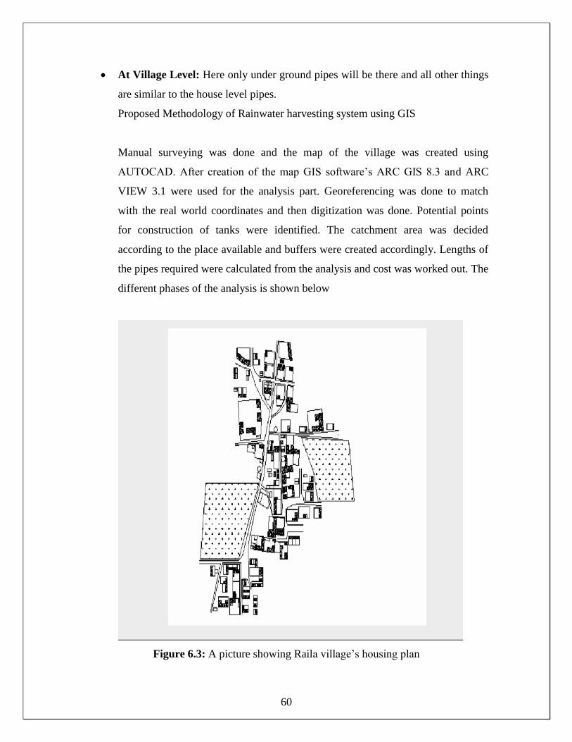
60
At Village Level: Here only under ground pipes will be there and all other things
are similar to the house level pipes.
Proposed Methodology of Rainwater harvesting system using GIS
Manual surveying was done and the map of the village was created using
AUTOCAD. After creation of the map GIS software’s ARC GIS 8.3 and ARC
VIEW 3.1 were used for the analysis part. Georeferencing was done to match
with the real world coordinates and then digitization was done. Potential points
for construction of tanks were identified. The catchment area was decided
according to the place available and buffers were created accordingly. Lengths of
the pipes required were calculated from the analysis and cost was worked out. The
different phases of the analysis is shown below
Figure 6.3: A picture showing Raila village’s housing plan
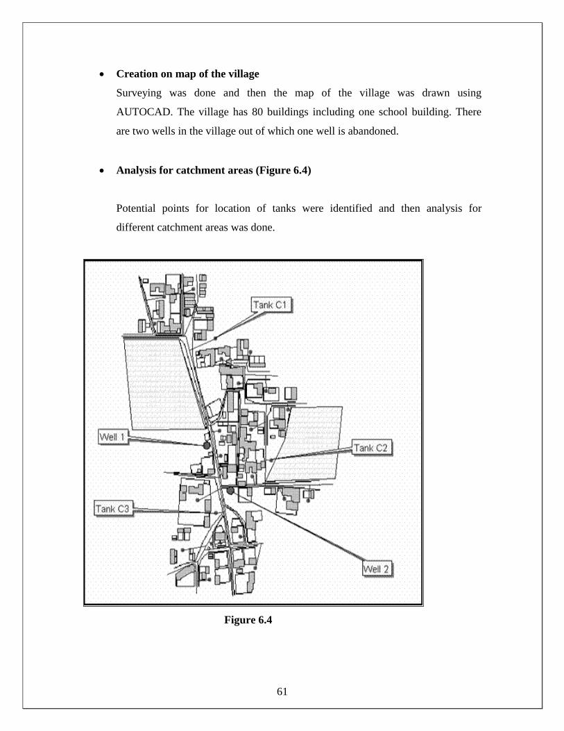
61
Creation on map of the village
Surveying was done and then the map of the village was drawn using
AUTOCAD. The village has 80 buildings including one school building. There
are two wells in the village out of which one well is abandoned.
Analysis for catchment areas (Figure 6.4)
Potential points for location of tanks were identified and then analysis for
different catchment areas was done.
Figure 6.4
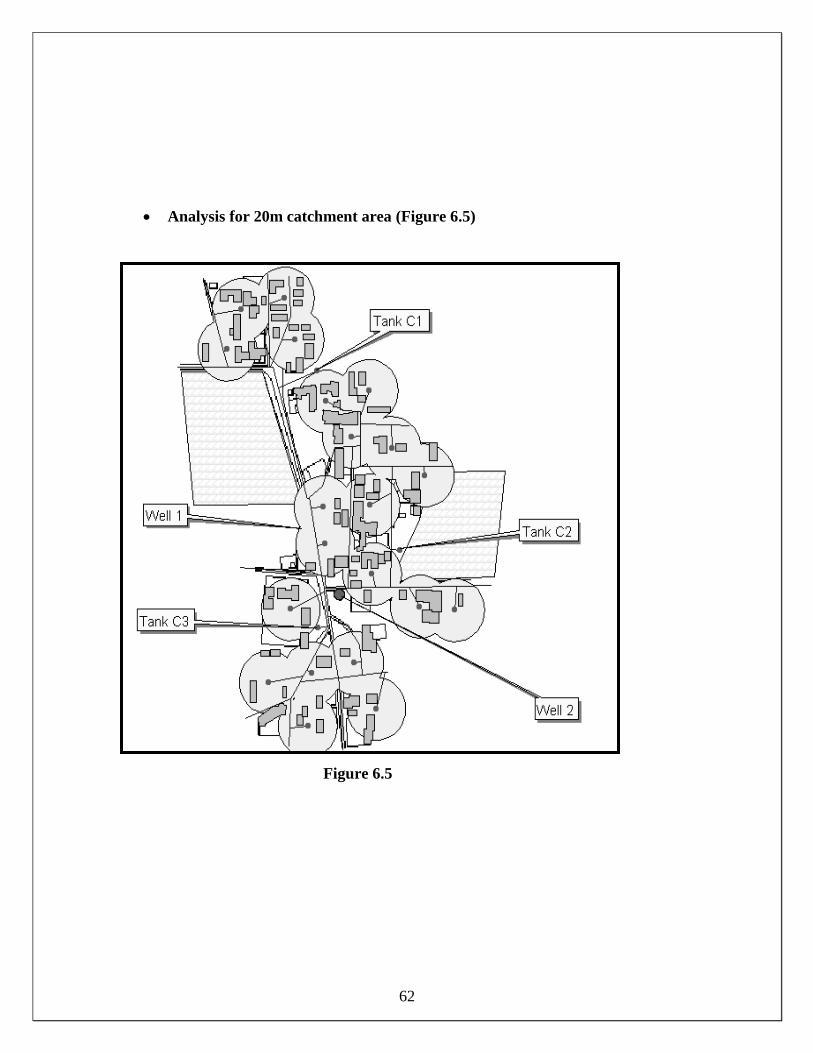
62
Analysis for 20m catchment area (Figure 6.5)
Figure 6.5
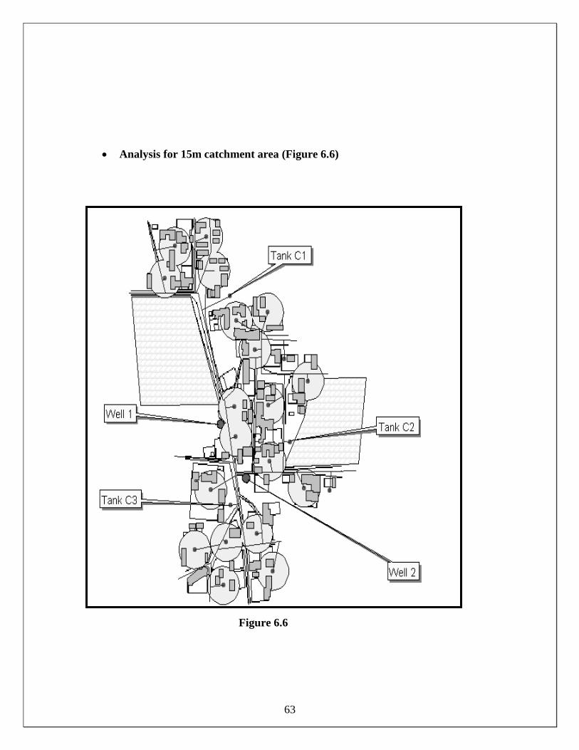
63
Analysis for 15m catchment area (Figure 6.6)
Figure 6.6
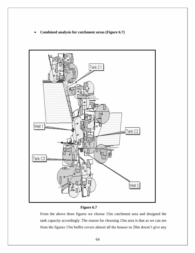
64
Combined analysis for catchment areas (Figure 6.7)
Figure 6.7
From the above three figures we choose 15m catchment area and designed the
tank capacity accordingly. The reason for choosing 15m area is that as we can see
from the figures 15m buffer covers almost all the houses so 20m doesn’t give any
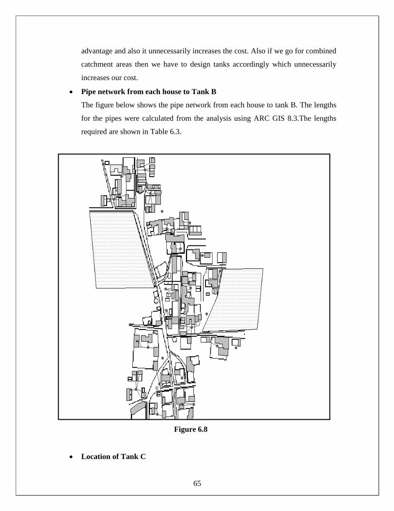
65
advantage and also it unnecessarily increases the cost. Also if we go for combined
catchment areas then we have to design tanks accordingly which unnecessarily
increases our cost.
Pipe network from each house to Tank B
The figure below shows the pipe network from each house to tank B. The lengths
for the pipes were calculated from the analysis using ARC GIS 8.3.The lengths
required are shown in Table 6.3.
Figure 6.8
Location of Tank C
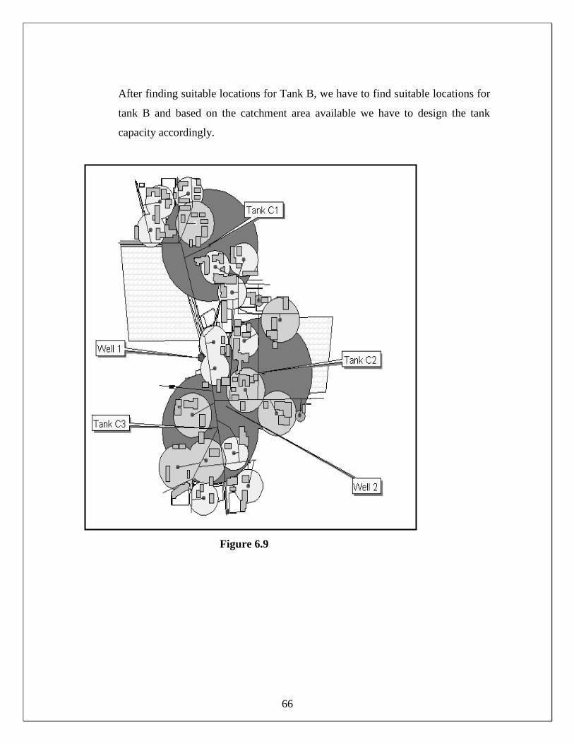
66
After finding suitable locations for Tank B, we have to find suitable locations for
tank B and based on the catchment area available we have to design the tank
capacity accordingly.
Figure 6.9
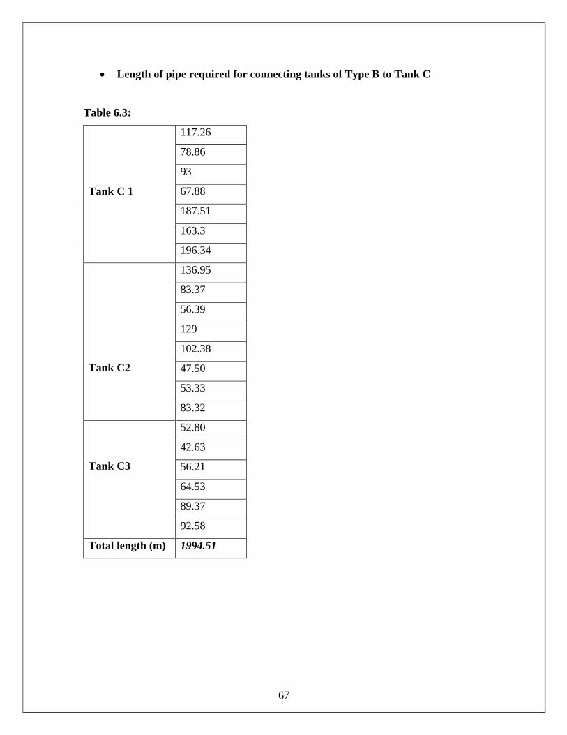
67
Length of pipe required for connecting tanks of Type B to Tank C
Table 6.3:
Tank C 1
117.26
78.86
93
67.88
187.51
163.3
196.34
Tank C2
136.95
83.37
56.39
129
102.38
47.50
53.33
83.32
Tank C3
52.80
42.63
56.21
64.53
89.37
92.58
Total length (m) 1994.51
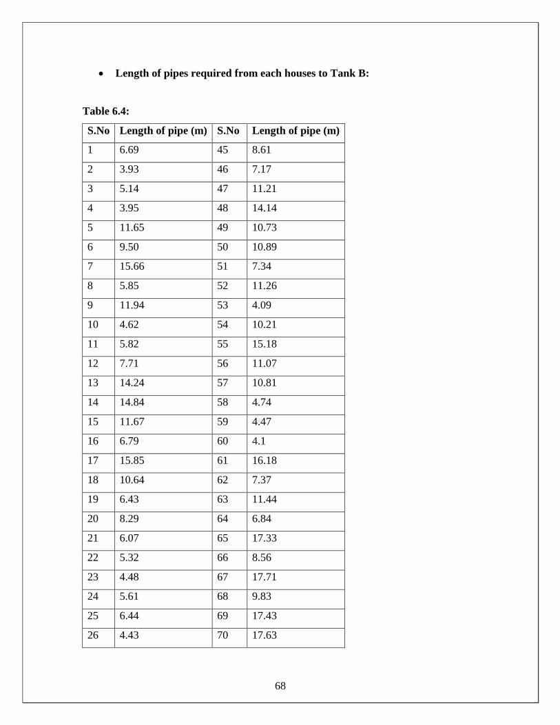
68
Length of pipes required from each houses to Tank B:
Table 6.4:
S.No Length of pipe (m) S.No Length of pipe (m)
1 6.69 45 8.61
2 3.93 46 7.17
3 5.14 47 11.21
4 3.95 48 14.14
5 11.65 49 10.73
6 9.50 50 10.89
7 15.66 51 7.34
8 5.85 52 11.26
9 11.94 53 4.09
10 4.62 54 10.21
11 5.82 55 15.18
12 7.71 56 11.07
13 14.24 57 10.81
14 14.84 58 4.74
15 11.67 59 4.47
16 6.79 60 4.1
17 15.85 61 16.18
18 10.64 62 7.37
19 6.43 63 11.44
20 8.29 64 6.84
21 6.07 65 17.33
22 5.32 66 8.56
23 4.48 67 17.71
24 5.61 68 9.83
25 6.44 69 17.43
26 4.43 70 17.63
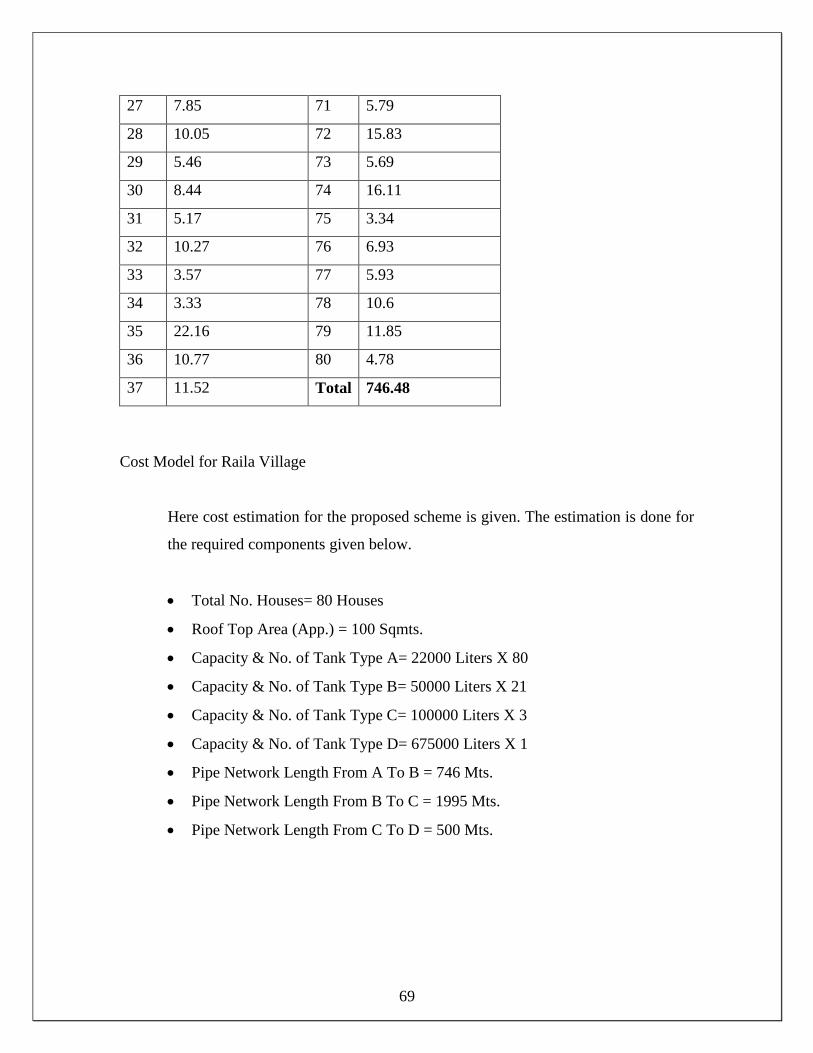
69
27 7.85 71 5.79
28 10.05 72 15.83
29 5.46 73 5.69
30 8.44 74 16.11
31 5.17 75 3.34
32 10.27 76 6.93
33 3.57 77 5.93
34 3.33 78 10.6
35 22.16 79 11.85
36 10.77 80 4.78
37 11.52 Total 746.48
Cost Model for Raila Village
Here cost estimation for the proposed scheme is given. The estimation is done for
the required components given below.
Total No. Houses= 80 Houses
Roof Top Area (App.) = 100 Sqmts.
Capacity & No. of Tank Type A= 22000 Liters X 80
Capacity & No. of Tank Type B= 50000 Liters X 21
Capacity & No. of Tank Type C= 100000 Liters X 3
Capacity & No. of Tank Type D= 675000 Liters X 1
Pipe Network Length From A To B = 746 Mts.
Pipe Network Length From B To C = 1995 Mts.
Pipe Network Length From C To D = 500 Mts.
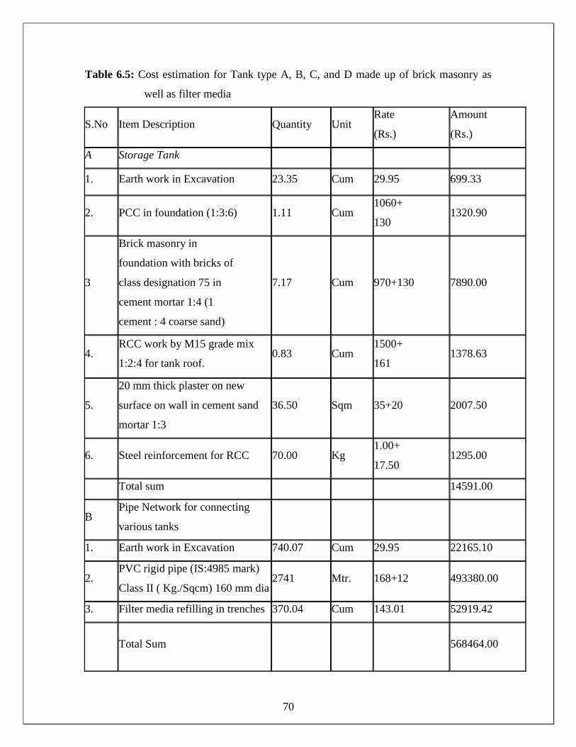
70
Table 6.5: Cost estimation for Tank type A, B, C, and D made up of brick masonry as
well as filter media
S.No Item Description Quantity Unit Rate
(Rs.)
Amount
(Rs.)
A Storage Tank
1. Earth work in Excavation 23.35 Cum 29.95 699.33
2. PCC in foundation (1:3:6) 1.11 Cum 1060+
130 1320.90
3
Brick masonry in
foundation with bricks of
class designation 75 in
cement mortar 1:4 (1
cement : 4 coarse sand)
7.17 Cum 970+130 7890.00
4. RCC work by M15 grade mix
1:2:4 for tank roof. 0.83 Cum
1500+
161 1378.63
5.
20 mm thick plaster on new
surface on wall in cement sand
mortar 1:3
36.50 Sqm 35+20 2007.50
6. Steel reinforcement for RCC 70.00 Kg 1.00+
17.50 1295.00
Total sum 14591.00
B Pipe Network for connecting
various tanks
1. Earth work in Excavation 740.07 Cum 29.95 22165.10
2. PVC rigid pipe (IS:4985 mark)
Class II ( Kg./Sqcm) 160 mm dia 2741 Mtr. 168+12 493380.00
3. Filter media refilling in trenches 370.04 Cum 143.01 52919.42
Total Sum 568464.00
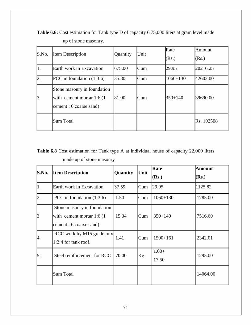
71
Table 6.6: Cost estimation for Tank type D of capacity 6,75,000 liters at gram level made
up of stone masonry.
S.No. Item Description Quantity Unit Rate
(Rs.)
Amount
(Rs.)
1. Earth work in Excavation 675.00 Cum 29.95 20216.25
2. PCC in foundation (1:3:6) 35.80 Cum 1060+130 42602.00
3
Stone masonry in foundation
with cement mortar 1:6 (1
cement : 6 coarse sand)
81.00 Cum 350+140 39690.00
Sum Total Rs. 102508
Table 6.8 Cost estimation for Tank type A at individual house of capacity 22,000 liters
made up of stone masonry
S.No. Item Description Quantity Unit Rate
(Rs.)
Amount
(Rs.)
1. Earth work in Excavation 37.59 Cum 29.95 1125.82
2. PCC in foundation (1:3:6) 1.50 Cum 1060+130 1785.00
3
Stone masonry in foundation
with cement mortar 1:6 (1
cement : 6 coarse sand)
15.34 Cum 350+140 7516.60
4. RCC work by M15 grade mix
1:2:4 for tank roof. 1.41 Cum 1500+161 2342.01
5. Steel reinforcement for RCC 70.00 Kg 1.00+
17.50 1295.00
Sum Total 14064.00