Embed Size (px)
Citation preview
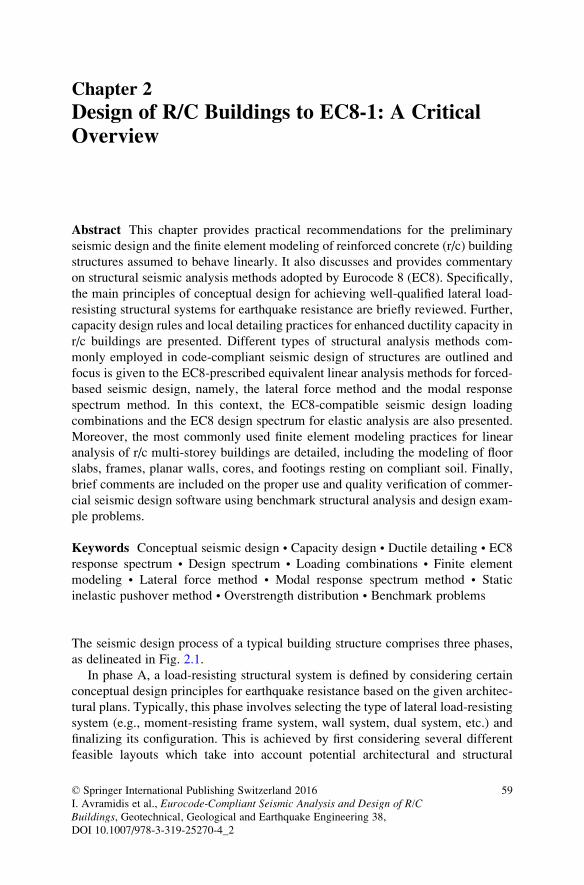
Chapter 2
Design of R/C Buildings to EC8-1: A CriticalOverview
Abstract This chapter provides practical recommendations for the preliminary
seismic design and the finite element modeling of reinforced concrete (r/c) building
structures assumed to behave linearly. It also discusses and provides commentary
on structural seismic analysis methods adopted by Eurocode 8 (EC8). Specifically,
the main principles of conceptual design for achieving well-qualified lateral load-
resisting structural systems for earthquake resistance are briefly reviewed. Further,
capacity design rules and local detailing practices for enhanced ductility capacity in
r/c buildings are presented. Different types of structural analysis methods com-
monly employed in code-compliant seismic design of structures are outlined and
focus is given to the EC8-prescribed equivalent linear analysis methods for forced-
based seismic design, namely, the lateral force method and the modal response
spectrum method. In this context, the EC8-compatible seismic design loading
combinations and the EC8 design spectrum for elastic analysis are also presented.
Moreover, the most commonly used finite element modeling practices for linear
analysis of r/c multi-storey buildings are detailed, including the modeling of floor
slabs, frames, planar walls, cores, and footings resting on compliant soil. Finally,
brief comments are included on the proper use and quality verification of commer-
cial seismic design software using benchmark structural analysis and design exam-
ple problems.
Keywords Conceptual seismic design • Capacity design • Ductile detailing • EC8
response spectrum • Design spectrum • Loading combinations • Finite element
modeling • Lateral force method • Modal response spectrum method • Static
inelastic pushover method • Overstrength distribution • Benchmark problems
The seismic design process of a typical building structure comprises three phases,
as delineated in Fig. 2.1.
In phase A, a load-resisting structural system is defined by considering certain
conceptual design principles for earthquake resistance based on the given architec-
tural plans. Typically, this phase involves selecting the type of lateral load-resisting
system (e.g., moment-resisting frame system, wall system, dual system, etc.) and
finalizing its configuration. This is achieved by first considering several different
feasible layouts which take into account potential architectural and structural
© Springer International Publishing Switzerland 2016
I. Avramidis et al., Eurocode-Compliant Seismic Analysis and Design of R/CBuildings, Geotechnical, Geological and Earthquake Engineering 38,
DOI 10.1007/978-3-319-25270-4_2
59
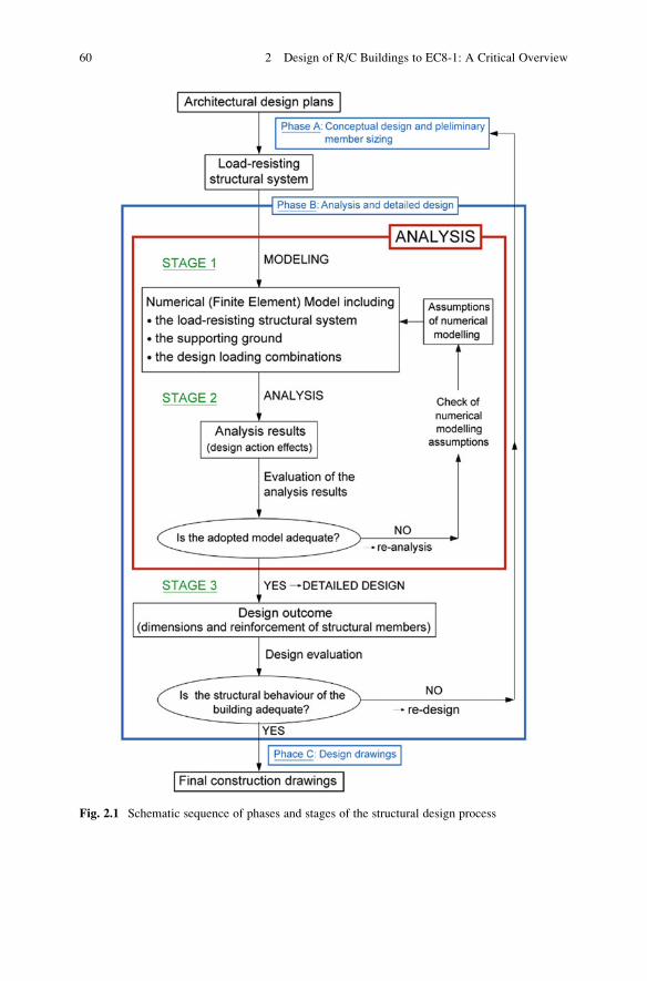
Fig. 2.1 Schematic sequence of phases and stages of the structural design process
60 2 Design of R/C Buildings to EC8-1: A Critical Overview

constraints, building regulations, construction management and cost-effectiveness
issues, as well as various other case-specific provisions. Next, the design structural
engineer chooses a small set out of these feasible layouts for further investigation
by relying heavily on his/her accumulated experience, expert judgement, and
personal design preferences. The chosen layouts are examined to sufficient detail
to make a quantitative comparison possible, and to finalize the configuration of the
lateral load-resisting system to be considered in the second phase (phase B) of the
seismic design process. To this aim, phase A involves undertaking only some
preliminary (approximate) analysis steps to determine the initial sizes of r/c struc-
tural members.
In phase B, a finite element model (also called a mathematical or computational
or structural analysis model; see elsewhere (Mac Leod 1995)) of the load-resisting
system adopted from phase A is first developed (Stage 1: Modeling in Fig. 2.1).
This is accomplished by relying on certain modeling assumptions and simplifica-
tions which are based on the in-depth knowledge of the analysis methods to be used.
This model includes the building foundation system and superstructure and should
take into consideration the compliance of the supporting ground, if deemed neces-
sary. Next, the finite element model is used to calculate the “effects” (i.e., internal
stress resultants/forces and deformations of structural members) of the design
“actions” (i.e., design loading combinations including the seismic design loads)
prescribed by the relevant design code regulations (Stage 2: Analysis in Fig. 2.1).
At the end of this second stage, certain verification checks against (primarily)
deformation-based criteria are made to ensure that the adopted dimensions of
structural members are adequate. If these criteria are met, structural members are
designed in detail (Stage 3: Detailed design in Fig. 2.1) to finalize their dimensions
and the required reinforcement using the results (calculated action effects) of the
analysis stage. The detailed design stage involves several verification checks to
ensure that adequate levels of strength and ductility are achieved by considering
appropriate longitudinal and transverse reinforcement at critical (energy dissipa-
tion) zones of structural members. Meeting these verification checks may require
modifications of the adopted dimensions in a number of r/c structural members and,
therefore, further re-analysis and re-design steps may be necessary to iteratively
optimize the design of the load resisting structural system.
Finally, phase C involves the preparation of all necessary construction drawings
and design plans incorporating the required reinforcement details and structural
member dimensions for the practical implementation building design.
From the above brief overview of the seismic design process of a typical r/c
building, it is seen that there are, at least, four stages involving critical choices and
decisions to be made by the design engineer based on his/her knowledge and
experience rather than on “black-box” types of calculation automated in commer-
cial structural analysis and design software. These stages are listed below starting
from those requiring more input on behalf of the designer in terms of experience
and expert judgment:
2 Design of R/C Buildings to EC8-1: A Critical Overview 61
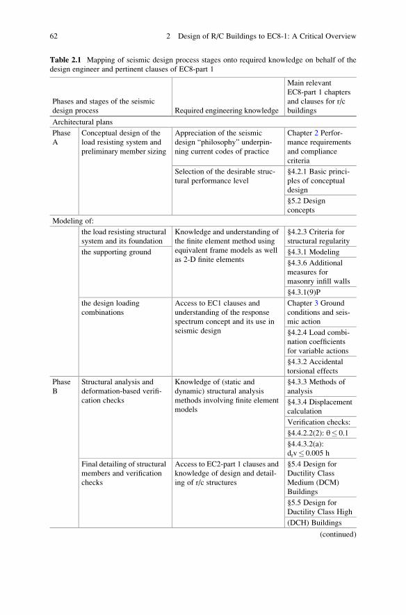
Table 2.1 Mapping of seismic design process stages onto required knowledge on behalf of the
design engineer and pertinent clauses of EC8-part 1
Phases and stages of the seismic
design process Required engineering knowledge
Main relevant
EC8-part 1 chapters
and clauses for r/c
buildings
Architectural plans
Phase
A
Conceptual design of the
load resisting system and
preliminary member sizing
Appreciation of the seismic
design “philosophy” underpin-
ning current codes of practice
Chapter 2 Perfor-
mance requirements
and compliance
criteria
Selection of the desirable struc-
tural performance level
§4.2.1 Basic princi-
ples of conceptual
design
§5.2 Design
concepts
Modeling of:
the load resisting structural
system and its foundation
Knowledge and understanding of
the finite element method using
equivalent frame models as well
as 2-D finite elements
§4.2.3 Criteria for
structural regularity
the supporting ground §4.3.1 Modeling
§4.3.6 Additional
measures for
masonry infill walls
§4.3.1(9)P
the design loading
combinations
Access to EC1 clauses and
understanding of the response
spectrum concept and its use in
seismic design
Chapter 3 Ground
conditions and seis-
mic action
§4.2.4 Load combi-
nation coefficients
for variable actions
§4.3.2 Accidental
torsional effects
Phase
B
Structural analysis and
deformation-based verifi-
cation checks
Knowledge of (static and
dynamic) structural analysis
methods involving finite element
models
§4.3.3 Methods of
analysis
§4.3.4 Displacement
calculation
Verification checks:
§4.4.2.2(2): θ� 0.1
§4.4.3.2(a):
drv� 0.005 h
Final detailing of structural
members and verification
checks
Access to EC2-part 1 clauses and
knowledge of design and detail-
ing of r/c structures
§5.4 Design for
Ductility Class
Medium (DCM)
Buildings
§5.5 Design for
Ductility Class High
(DCH) Buildings
(continued)
62 2 Design of R/C Buildings to EC8-1: A Critical Overview
– conceptual design of the lateral load-resisting system,
– development of the numerical (finite element) model,
– critical appraisal and verification of analysis results, and
– detailed design of structural members.
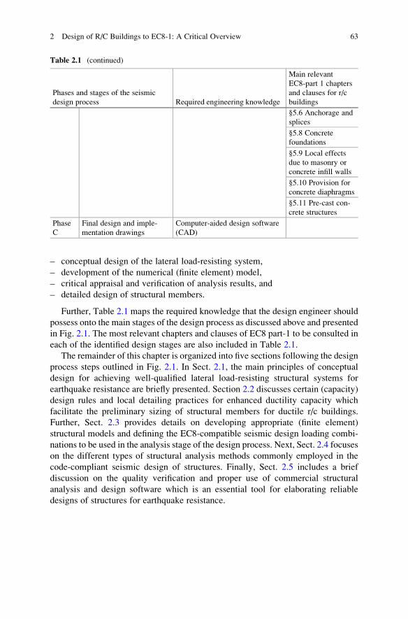
Further, Table 2.1 maps the required knowledge that the design engineer should
possess onto the main stages of the design process as discussed above and presented
in Fig. 2.1. The most relevant chapters and clauses of EC8 part-1 to be consulted in
each of the identified design stages are also included in Table 2.1.
The remainder of this chapter is organized into five sections following the design
process steps outlined in Fig. 2.1. In Sect. 2.1, the main principles of conceptual
design for achieving well-qualified lateral load-resisting structural systems for
earthquake resistance are briefly presented. Section 2.2 discusses certain (capacity)
design rules and local detailing practices for enhanced ductility capacity which
facilitate the preliminary sizing of structural members for ductile r/c buildings.
Further, Sect. 2.3 provides details on developing appropriate (finite element)
structural models and defining the EC8-compatible seismic design loading combi-
nations to be used in the analysis stage of the design process. Next, Sect. 2.4 focuses
on the different types of structural analysis methods commonly employed in the
code-compliant seismic design of structures. Finally, Sect. 2.5 includes a brief
discussion on the quality verification and proper use of commercial structural
analysis and design software which is an essential tool for elaborating reliable
designs of structures for earthquake resistance.
Table 2.1 (continued)
Phases and stages of the seismic
design process Required engineering knowledge
Main relevant
EC8-part 1 chapters
and clauses for r/c
buildings
§5.6 Anchorage and
splices
§5.8 Concrete
foundations
§5.9 Local effects
due to masonry or
concrete infill walls
§5.10 Provision for
concrete diaphragms
§5.11 Pre-cast con-
crete structures
Phase
C
Final design and imple-
mentation drawings
Computer-aided design software
(CAD)
2 Design of R/C Buildings to EC8-1: A Critical Overview 63
2.1 Conceptual Design Principlesfor Earthquake-Resistant Buildings
2.1.1 Desirable Attributes of the Lateral Load-ResistingStructural System and Fundamental Rules
In the recent past, the structural layout of ordinary buildings had to be kept
relatively simple and straightforward from a structural analysis viewpoint to ensure
that the analysis and detailing steps undertaken by structural engineers were
accomplished in reasonable time in the absence of high computational power.
During the past two decades, the advent of powerful low-cost computers and
dependable commercial finite element-based analysis and design software have
built confidence among practicing structural engineers that “almost any structural
layout” can be readily and swiftly designed. In this regard, reduced time and effort
is spent in the first phase of the design process of common buildings (i.e., the
conceptual design of the load resisting structural system), since the second phase
(i.e., modeling, analysis, and detailing) is seen as a mere “computer data input”
problem. Thus, structural engineers may sometimes find themselves obliged to
design structures within tight timescales based on hastily conceived structural
layouts of questionable rationale and on their corresponding mathematical (com-
putational) models using three-dimensional linear finite element structural analysis
software. This approach is erroneous, especially when it comes to structures
subjected to seismic excitations. The reason is that the deficiencies of an inadequatelateral load-resisting structural system inherently vulnerable to seismic inputaction cannot be ameliorated or rectified at any later phase in the design and/orconstruction process (i.e., not even by the most consistent and detailed structuralanalysis and detailing steps). This is true irrespective of the adopted type of lateral
load-resisting structural system of the structural analysis method of choice. In fact,
a deficient structural layout adopted during the conceptual design stage can hardly
ever be brought to the same level of seismic performance with a structural layout
satisfying certain qualitative criteria and rules in line with the seismic design
philosophy adopted by the current codes of practice.
In this respect, it can be readily recognized that the conceptual design stage is the
one least dominated by the use of automated software. It relies heavily on the
experience, expertise, and subjective preference of the design engineer to accom-
modate the case-dependent architectural requirements. Certain research efforts for
the development of automated computational tools (relying on principles from the
field of Artificial Intelligence) to support and assist design engineers in composing
alternative structural layouts have been made in the past few decades (see,
e.g. (Avramidis et al. 1995; Berrais 2005)). However, such “knowledge-based
expert systems” have not yet reached a satisfactory level of maturity and are not
considered to be capable of offering enhanced solutions beyond the average level of
creativity of structural design experts. Despite being subjective in many respects,
there exist qualitative rules and criteria for facilitating the conceptual design phase.
64 2 Design of R/C Buildings to EC8-1: A Critical Overview
Most of these conceptual design rules have already been listed in Sect. 1.2.5 under
the first of the three essential classes of requirements for ductile structural behav-
iour under design seismic action, namely the maximization of dispersion of the
seismic input energy within the lateral load-resisting structural system. Further,
some of these rules are also related to the requirements for prevention of (prema-
ture) global structural instability/collapse and for maximization of the dissipation of
the seismic input energy via hysteretic behaviour. However, the last two require-
ments are more closely related to capacity design rules and structural member
detailing for ductility which are discussed in some detail in the next section.
Focusing on the specifics of EC8, the following list of desirable attributes that
structural layouts should observe to expedite the code-compliant seismic design
process is included in clause §4.2.1 of EC8- Basic principles of conceptual design
for earthquake resistant building structures:
– Structural simplicity,
– Uniformity, symmetry (regularity), and redundancy,
– Bi-directional resistance and stiffness,
– Torsional resistance and stiffness,
– Diaphragmatic behaviour at the storey level,
– Foundation capable of transmitting the superstructure forces to the ground.
Certain brief clarification notes highlighting the meaning and importance of the
above qualitative conceptual design rules follow.
Structural simplicity
A simple load resisting structural system in plan and elevation ensures that
unambiguously identifiable, continuous, and relatively short stress/load paths
exist through which all external loads applied statically (gravitational loads) and
dynamically (lateral inertial seismic loads) are transmitted from building super-
structure to its foundation and the supporting ground. Complex or indirect load
paths (e.g., due to columns supported by beams) may result in undue local stress and
strain concentrations and, thus, to increased local strength and ductility demands. In
the inelastic range of structural behaviour (which is expected to be severe for large
values of the behaviour factor q), such local ductility demands may not be ade-
quately captured by code-prescribed linear types of analysis methods. Conse-
quently, the code-compliant seismic design process becomes inherently less
reliable in accounting for and properly verifying the expected local ductility
demands for structural layouts of increased complexity. Therefore, safeguarding
simplicity and clarity of the lateral load resisting system at the conceptual design
stage is essential for reducing the inherent uncertainties associated with the anal-
ysis, detailing, and construction of earthquake resistant buildings complying with
the intended code-specific requirements.
Uniformity, symmetry and redundancy
It is well established through field observations, large scale experimental results,
and computational/analytical research work that building structures with even
2.1 Conceptual Design Principles for Earthquake-Resistant Buildings 65
(uniform) and symmetric distribution of inertial (mass), stiffness, and strength
properties in plan and elevation generally exhibit favourable dynamic/vibration
response to severe strong ground motions compared to irregular structures with
non-uniform distribution of one or more of the above properties. Further, in uniform
and symmetric building structures, undue local concentrations of deformation/
ductility and stress demands in a small number of structural elements are prevented.
Specifically, “short column” formation is avoided by ensuring even stiffness dis-
tribution in plan and elevation, floor/slab rotations about the vertical (gravitational)
axis are limited since the center of gravity lies close to the horizontal shear
resistance center in plan (see also Fig. 2.2), and relative (differential) lateral and
vertical displacements among structural members are minimized. Note that mass
distribution is mainly related to the global geometrical shape of the building in plan
and elevation, (lateral) stiffness distribution depends on the location and size of
vertical structural members (columns, walls, and cores) in plan, while strength
distribution is mostly associated with the longitudinal steel reinforcement ratios in
structural members. Thus, in-plan symmetry does not necessarily imply in-plan
uniformity (regularity), which is primarily related to the “compactness” of the
building footprint (in-plan envelop). For example, H-shaped and cross-shaped
plans are symmetric, but they are not uniform since they may have large in-plan
recesses or elongated wings, respectively.
Redundancy allows for the development of alternative load paths upon plastic
hinge formations or other local modes of failure at structural members. Therefore,
redundancy is necessary to ensure redistribution of stresses which reduces the
adverse effects of local (unanticipated) failures at structural members and, thus,
the inherent uncertainty of the achieved seismic design. Further, redundancy
increases the overall exhibited global “overstrength” of the lateral load-resisting
structural system and its global ductility capacity.
Bi-directional resistance and stiffness
The horizontal design seismic action consists of two independent and simulta-
neously applied orthogonal components of the same order of magnitude. Therefore,
the vertical structural members should be ideally arranged along two orthogonal
axes (“principal axes”). Further, the overall level of lateral “resistance” of the
structure against the seismic action in terms of stiffness, strength, and ductility
should be similar along both principal axes.
Torsional resistance and stiffness
The torsional (rotational about the gravitational axis) seismic excitation compo-
nent is typically negligible. However, building structures subjected to horizontal
translational seismic excitations exhibit both translational and torsional displace-
ments. This is due to “structural” and/or “accidental” in-plan eccentricities, that is,
distances between the center of gravity and the horizontal shear resistance center at
each storey level due to lack of perfect in-plan symmetry and/or non-uniform mass
distribution of live gravitational loads. Therefore, the lateral load-resisting struc-
tural system should possess adequate torsional stiffness and strength. This is
66 2 Design of R/C Buildings to EC8-1: A Critical Overview
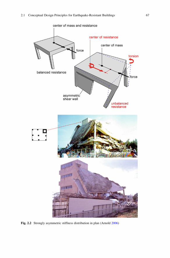
Fig. 2.2 Strongly asymmetric stiffness distribution in plan (Arnold 2006)
2.1 Conceptual Design Principles for Earthquake-Resistant Buildings 67
practically satisfied by ensuring that adequately stiff and strong vertical structural
members are aligned (symmetrically) on or close to the perimeter of buildings.
Diaphragmatic behaviour at storey level
Concrete slabs at each storey level of r/c buildings acting as rigid in-plane
diaphragms contribute significantly to a favourable seismic structural response
behaviour. This is because they minimize horizontal relative (differential) displace-
ments between structural members of the lateral load-resisting system at each
storey level and ensure that all points of each storey undergo a single rotation
about its gravitational (normal to the slab plane) axis. Further, they ensure that
vertical structural members are “tied together” and that the horizontal seismic
inertial forces are evenly distributed at these members according to their individual
lateral stiffness. This rigid-disk like “diaphragmatic” behaviour at each storey level
of buildings is achieved when slabs are compact, adequately stiff in their plane, and
have relatively small in-plan aspect ratios and few/small floor openings.
Adequate foundation
A stiff and strong foundation tying the base of all vertical structural members of
the superstructure together well in a grid-like layout is essential for a favourable
structural response to earthquake excitations. This is because it minimizes the
adverse effects of spatially incoherent ground motion, while preventing differen-
tial/relative settlements and horizontal translations at the foundation level. Further,
it minimizes potential relative translations and rotations about the horizontal axes at
the base of vertical structural members. Lastly, an adequately stiff and strong
foundation evenly distributes the lateral seismic forces (in the form of base shears)
concentrated primarily in the stiffer vertical structural members to the supporting
grounds For the same reasons, the consideration of basements with perimetric r/c
walls during the conceptual design stage is also recommended.
A more detailed list of practical guidelines and rules for facilitating the concep-
tual design for the earthquake resistance phase are provided in Table 2.2 (Penelis
and Kappos 1997). Though not compulsory for code-compliant seismic design, they
ensure the effectiveness and reliability of the current earthquake-resistant design
philosophy adopting a partial protection against damage for design seismic action.
That is, they allow for adopting relatively high values of behaviour factor q in
conjunction with (equivalent) linear structural analysis methods, as detailed in Sect.
1.2.4. In general, they contribute to a favourable structural behaviour of the lateral
load-resisting system for the case of severe earthquake shaking under which
structures will exhibit strong inelastic behaviour, ensuring that inelastic response
will only take place in the superstructure where damage can be visually detected
and repaired. It is further emphasized that the above rules should be adopted even
when the structure is expected to exhibit insignificant inelastic behaviour under the
design seismic action (i.e., case of adopting relatively small values of behaviour
factor q, e.g., q� 1.75 – high level of seismic performance for the design earth-
quake), since they ensure favourable static/dynamic structural behaviour for
(almost) linear elastic structures as well.
68 2 Design of R/C Buildings to EC8-1: A Critical Overview
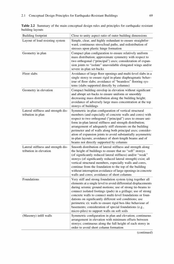
Table 2.2 Summary of the main conceptual design rules and principles for earthquake resistant
building layouts
Building footprint Close to unity aspect ratio of outer building dimensions
Layout of load resisting system Simple, clear, and highly redundant to ensure straightfor-
ward, continuous stress/load paths, and redistribution of
stresses upon plastic hinge formation
Geometry in plan Compact plan configuration to ensure relatively uniform
mass distribution; approximate symmetry with respect to
two orthogonal (“principal”) axes; consideration of expan-
sion joints to “isolate” unavoidable elongated wings and/or
severe in-plan set-backs
Floor slabs Avoidance of large floor openings and multi-level slabs in a
single storey to ensure rigid in-plane diaphragmatic behav-
iour of floor slabs; avoidance of “beamless” flooring sys-
tems (slabs supported directly by columns)
Geometry in elevation Compact building envelop in elevation without significant
and abrupt set-backs to ensure uniform or smoothly
decreasing mass distribution along the building height;
avoidance of adversely large mass concentration at the top
storeys of buildings
Lateral stiffness and strength dis-
tribution in plan
Symmetric in-plan configuration of vertical structural
members (and especially of concrete walls and cores) with
respect to two orthogonal (“principal”) axes to ensure uni-
form in-plan lateral stiffness and strength distribution;
arrangement of adequately stiff elements on the building
perimeter and of walls along both principal axes; consider-
ation of expansion joints to avoid substantially asymmetric
in-plan layouts; avoidance of short-length beams and of
beams not directly supported by columns
Lateral stiffness and strength dis-
tribution in elevation
Smooth distribution of lateral stiffness and strength along
the height of buildings to ensure that no “soft” storeys
(of significantly reduced lateral stiffness) and/or “weak”
storeys (of significantly reduced lateral strength) exist; all
vertical structural members, especially walls and cores,
continue from the foundation to the top of the building
without interruption avoidance of large openings in concrete
walls and cores; avoidance of short columns
Foundations Very stiff and strong foundation system tying together all
elements at a single level to avoid differential displacements
during seismic ground motions; use of strong tie-beams to
connect isolated footings (pads) in a grillage; use of strong
concrete walls to connect multi-level foundations or foun-
dations on significantly different soil conditions; use
perimetric r/c walls to ensure rigid box-like behaviour of
basements; consideration of special foundations (e.g.,
micro-piles) to support walls on soft soils
(Masonry) infill walls Symmetric configuration in plan and elevation; continuous
arrangement in elevation with minimum offsets between
storeys; continuous along the full height of each storey in
order to avoid short column formation
(continued)
2.1 Conceptual Design Principles for Earthquake-Resistant Buildings 69
2.1.2 Frequently Observed Deficiencies in StructuralLayouts
Structural layouts that do not possess one or more of the attributes discussed in the
previous sub-section due to poor conceptual design or unavoidable architecturally-
driven constraints may possess a reduced (global) ductility capacity. Arguably,
most partial or global building collapses observed in severe historical seismic
events are due to adverse effects caused by not complying with one or more of
the fundamental conceptual seismic design principles. In this respect, it is instruc-
tive to highlight the potential adverse effects of adopting structural layouts that do
not follow or significantly deviate from the desirable conceptual design principles
summarized in Table 2.2. To this aim, Table 2.3 lists the most commonly encoun-
tered deficiencies of structural layouts from the seismic design perspective and the
effects that these may have during severe earthquake shaking.
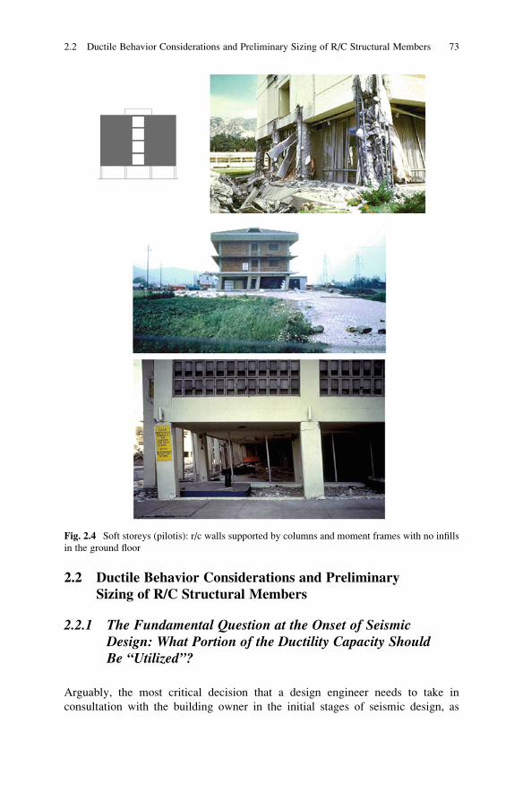
Special attention should be paid to the cases of buildings with:
– excessive asymmetry in the in-plan distribution of lateral stiffness which poses
extreme ductility demands on vertical structural members along the “soft” sides
of the building due to torsional displacement (Fig. 2.2),
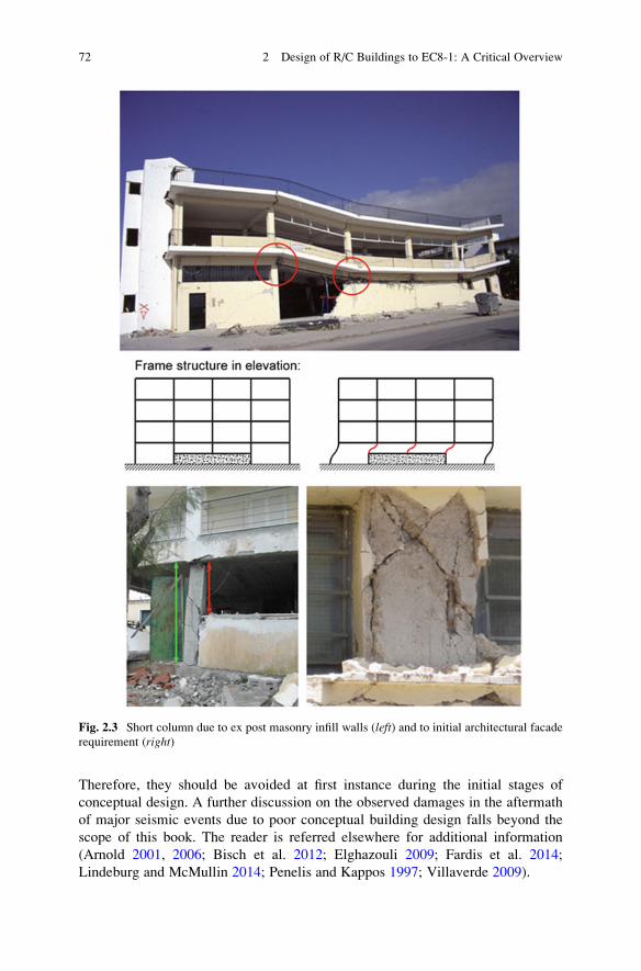
– short columns which attract significant shear stresses and, thus, under severe
ground shaking, may be driven to brittle modes of failure (Fig. 2.3),
– a “soft” ground floor (“pilotis”, as it is commonly referred to, mainly in Med-
iterranean countries) which generates considerably high and localised ductility
demands that commonly lead to premature “storey” types of global plastic
mechanisms of reduced global ductility (Figs. 2.4, and 2.13).
The above are considered to be the most common deficiencies observed in practice
that result in significant and typically difficult to repair damages or even in partial or
total building collapse depending on the level of the induced seismic action.
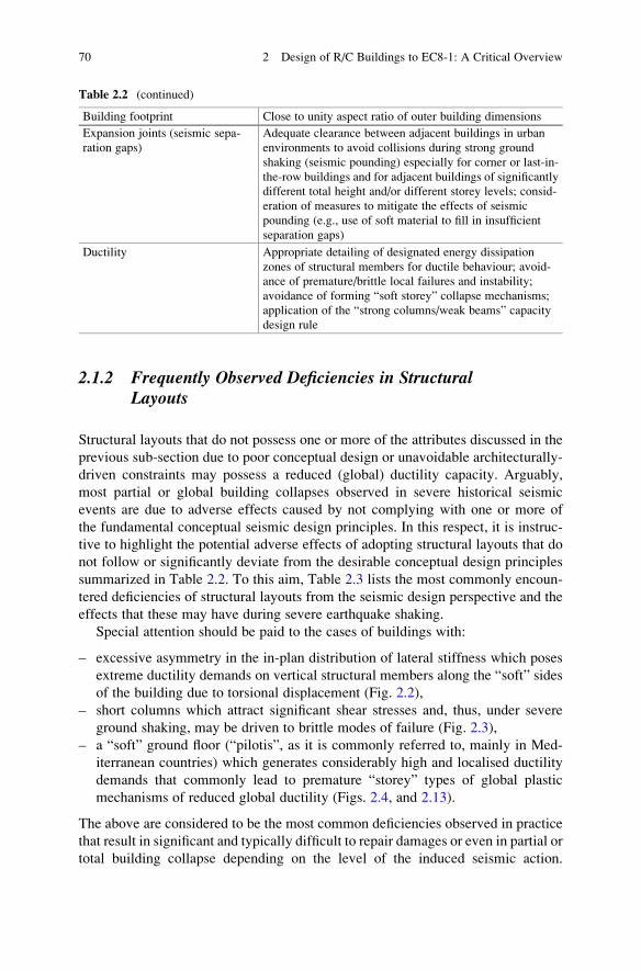
Table 2.2 (continued)
Building footprint Close to unity aspect ratio of outer building dimensions
Expansion joints (seismic sepa-
ration gaps)
Adequate clearance between adjacent buildings in urban
environments to avoid collisions during strong ground
shaking (seismic pounding) especially for corner or last-in-
the-row buildings and for adjacent buildings of significantly
different total height and/or different storey levels; consid-
eration of measures to mitigate the effects of seismic
pounding (e.g., use of soft material to fill in insufficient
separation gaps)
Ductility Appropriate detailing of designated energy dissipation
zones of structural members for ductile behaviour; avoid-
ance of premature/brittle local failures and instability;
avoidance of forming “soft storey” collapse mechanisms;
application of the “strong columns/weak beams” capacity
design rule
70 2 Design of R/C Buildings to EC8-1: A Critical Overview
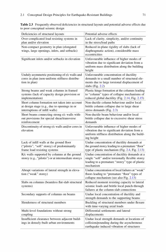
Table 2.3 Frequently observed deficiencies in structural layouts and potential adverse effects due
to poor conceptual seismic design
Deficiencies of structural layouts Potential adverse effects
Over-complicated load resisting systems in
plan and/or elevation
Lack of clarity, simplicity, and/or continuity
in the stress/load paths
Non-compact geometry in plan (elongated
wings, large openings, inlets, and setbacks)
Reduced in-plane rigidity of slabs (lack of
diaphragmatic action), considerable mass
eccentricities
Significant inlets and/or setbacks in elevation Unfavourable influence of higher modes of
vibration due to significant deviation from a
uniform mass distribution along the building
height
Unduly asymmetric positioning of r/c walls and
cores in plan (non-uniform stiffness distribu-
tion in plan)
Unfavourable concentration of ductility
demands to a small number of structural ele-
ments due to large torsional displacement of
slabs (Fig. 2.2)
Strong beams and weak columns in framed
systems (lack of capacity design provision or
implementation)
Plastic hinge formation at the columns leading
to “column” types of collapse mechanisms of
reduced global ductility (Fig. 2.14, Fig. 2.15)
Short column formation not taken into account
at design stage (e.g., due to openings in or
interruptions of infill walls)
Non-ductile column behaviour and/or local
brittle column collapse due to large shear
stress demands (Fig. 2.3)
Short beams connecting strong r/c walls with-
out provisions for special shear/transverse
reinforcement
Non-ductile beam behaviour and/or local
brittle collapse due to excessive shear stress
demands
Discontinuity of strong r/c walls and/or cores in
elevation
Unfavourable influence of higher modes of
vibration due to significant deviation from a
uniform stiffness distribution along the build-
ing height
Lack of infill walls at the ground floor
(“pilotis”, “soft” storey) of predominantly
frame load resisting systems
Undue concentration of ductility demands at
the ground storey leading to a premature “floor”
type of plastic mechanism (Fig. 2.4, Fig. 2.13)
R/c walls supported by columns at the ground
storey (e.g., “pilotis”) or at intermediate storeys
Undue concentration of ductility demands at a
single “soft” and/or torsionally flexible storey
leading to a premature “storey” type of plastic
mechanism
Abrupt variations of lateral strength in eleva-
tion (“weak” storey)
Undue concentration of local failures at “weak”
floors leading to “premature “floor” types of
collapse mechanism (see also Fig. 2.13)
Slabs on columns (beamless flat-slab structural
systems)
Reduced moment resisting capacity to lateral
seismic loads and brittle local punch-through
failures at the column-slab connections
Secondary supports of columns on beams Undue local concentration of ductility and
strength demands to the supporting beams
Slenderness of structural members Buckling of structural members under flexure
with time-varying axial loads
Multi-level foundations without strong
coupling
Differential settlements and lateral
displacements
Insufficient clearance between adjacent build-
ings in densely-built urban environments
Undue local strength demands at locations of
collision/pounding during the asynchronous
earthquake induced vibration of structures
2.1 Conceptual Design Principles for Earthquake-Resistant Buildings 71
Therefore, they should be avoided at first instance during the initial stages of
conceptual design. A further discussion on the observed damages in the aftermath
of major seismic events due to poor conceptual building design falls beyond the
scope of this book. The reader is referred elsewhere for additional information
(Arnold 2001, 2006; Bisch et al. 2012; Elghazouli 2009; Fardis et al. 2014;
Lindeburg and McMullin 2014; Penelis and Kappos 1997; Villaverde 2009).
Fig. 2.3 Short column due to ex post masonry infill walls (left) and to initial architectural facade
requirement (right)
72 2 Design of R/C Buildings to EC8-1: A Critical Overview
2.2 Ductile Behavior Considerations and PreliminarySizing of R/C Structural Members
2.2.1 The Fundamental Question at the Onset of SeismicDesign: What Portion of the Ductility Capacity ShouldBe “Utilized”?
Arguably, the most critical decision that a design engineer needs to take in
consultation with the building owner in the initial stages of seismic design, as
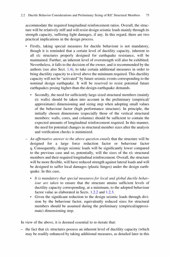
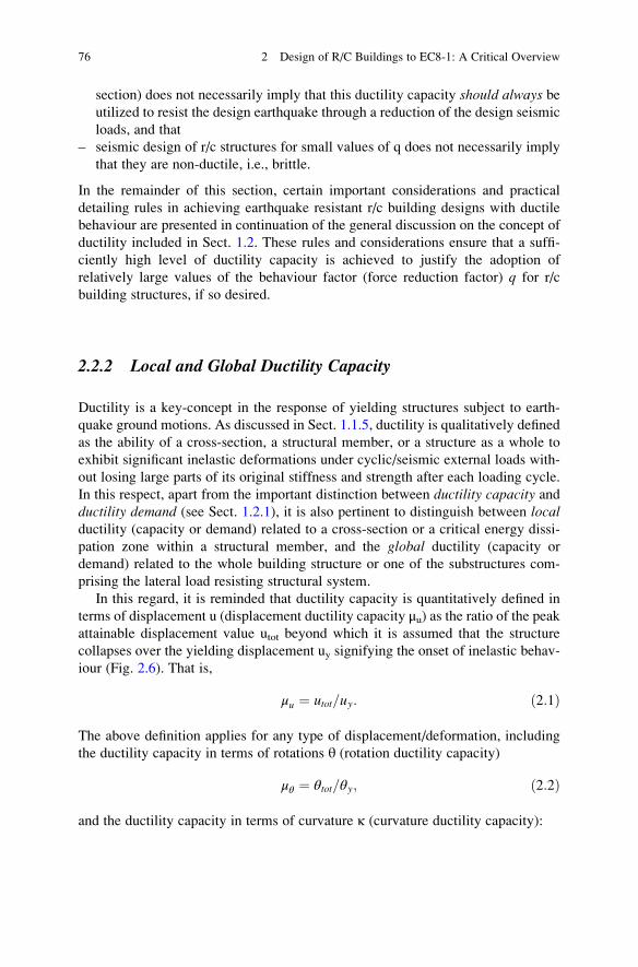
Fig. 2.4 Soft storeys (pilotis): r/c walls supported by columns and moment frames with no infills
in the ground floor
2.2 Ductile Behavior Considerations and Preliminary Sizing of R/C Structural Members 73
discussed in Sect. 1.4, concerns the desirable level of seismic protection against the
nominally defined “design earthquake” (or level of seismic performance). In fact,
this decision may significantly affect conceptual design considerations and prelim-
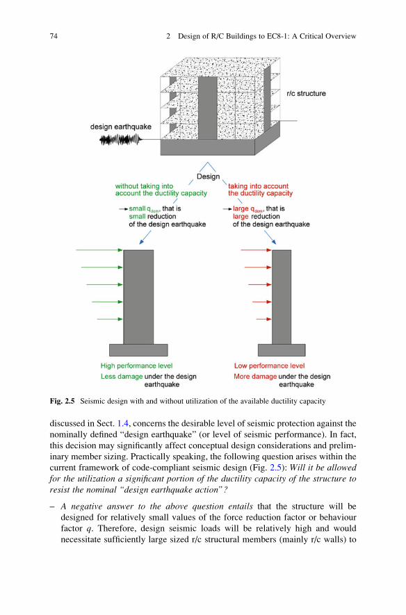
inary member sizing. Practically speaking, the following question arises within the
current framework of code-compliant seismic design (Fig. 2.5): Will it be allowedfor the utilization a significant portion of the ductility capacity of the structure toresist the nominal “design earthquake action”?
– A negative answer to the above question entails that the structure will be
designed for relatively small values of the force reduction factor or behaviour
factor q. Therefore, design seismic loads will be relatively high and would
necessitate sufficiently large sized r/c structural members (mainly r/c walls) to
Fig. 2.5 Seismic design with and without utilization of the available ductility capacity
74 2 Design of R/C Buildings to EC8-1: A Critical Overview
accommodate the required longitudinal reinforcement ratios. Overall, the struc-
ture will be relatively stiff and will resist design seismic loads mainly through its
strength capacity, suffering light damages, if any. In this regard, there are two
practical implications in the design process.
• Firstly, taking special measures for ductile behaviour is not mandatory,
though it is reminded that a certain level of ductility capacity, inherent to
all r/c structures properly designed for earthquake resistance, will be
maintained. Further, an inherent level of overstrength will also be exhibited.
Nevertheless, it falls to the decision of the owner, and is recommended by the
authors (see also Sect. 1.4), to take certain additional measures in order to
bring ductility capacity to a level above the minimum required. This ductility
capacity will not be “activated” by future seismic events corresponding to the
nominal design earthquake. It will be reserved to resist potential future
earthquakes posing higher-than-the-design-earthquake demands.
• Secondly, the need for sufficiently large-sized structural members (mainly
r/c walls) should be taken into account in the preliminary (empirical/
approximate) dimensioning and sizing step when adopting small values
of the behaviour factor (high performance structure). In principle, the
initially chosen dimensions (especially those of the vertical structural
members: walls, cores, and columns) should be sufficient to contain the
expected amounts of longitudinal reinforcement required. In this manner,
the need for potential changes in structural member sizes after the analysis
and verification checks is minimized.
– An affirmative answer to the above question entails that the structure will bedesigned for a large force reduction factor or behaviour factor
q. Consequently, design seismic loads will be significantly lower compared
to the previous case and so, potentially, will the sizes of the r/c structural
members and their required longitudinal reinforcement. Overall, the structure
will be more flexible, will have reduced strength against lateral loads and will
be designed to suffer local damages (plastic hinges) under the design earth-
quake. In this case,
• It is mandatory that special measures for local and global ductile behav-iour are taken to ensure that the structure attains sufficient levels of
ductility capacity corresponding, at a minimum, to the adopted behaviour
factor value as elaborated in Sects. 1.2.2 and 1.2.3.
• Given the significant reduction to the design seismic loads through divi-
sion by the behaviour factor, equivalently reduced sizes for structural
members should be assumed during the preliminary (empirical/approxi-
mate) dimensioning step.
In view of the above, it is deemed essential to re-iterate that:
– the fact that r/c structures possess an inherent level of ductility capacity (which
may be readily enhanced by taking additional measures, as detailed later in this
2.2 Ductile Behavior Considerations and Preliminary Sizing of R/C Structural Members 75
section) does not necessarily imply that this ductility capacity should always beutilized to resist the design earthquake through a reduction of the design seismic
loads, and that
– seismic design of r/c structures for small values of q does not necessarily imply
that they are non-ductile, i.e., brittle.
In the remainder of this section, certain important considerations and practical
detailing rules in achieving earthquake resistant r/c building designs with ductile
behaviour are presented in continuation of the general discussion on the concept of
ductility included in Sect. 1.2. These rules and considerations ensure that a suffi-
ciently high level of ductility capacity is achieved to justify the adoption of
relatively large values of the behaviour factor (force reduction factor) q for r/c
building structures, if so desired.
2.2.2 Local and Global Ductility Capacity
Ductility is a key-concept in the response of yielding structures subject to earth-
quake ground motions. As discussed in Sect. 1.1.5, ductility is qualitatively defined
as the ability of a cross-section, a structural member, or a structure as a whole to
exhibit significant inelastic deformations under cyclic/seismic external loads with-
out losing large parts of its original stiffness and strength after each loading cycle.
In this respect, apart from the important distinction between ductility capacity andductility demand (see Sect. 1.2.1), it is also pertinent to distinguish between localductility (capacity or demand) related to a cross-section or a critical energy dissi-
pation zone within a structural member, and the global ductility (capacity or
demand) related to the whole building structure or one of the substructures com-
prising the lateral load resisting structural system.
In this regard, it is reminded that ductility capacity is quantitatively defined in
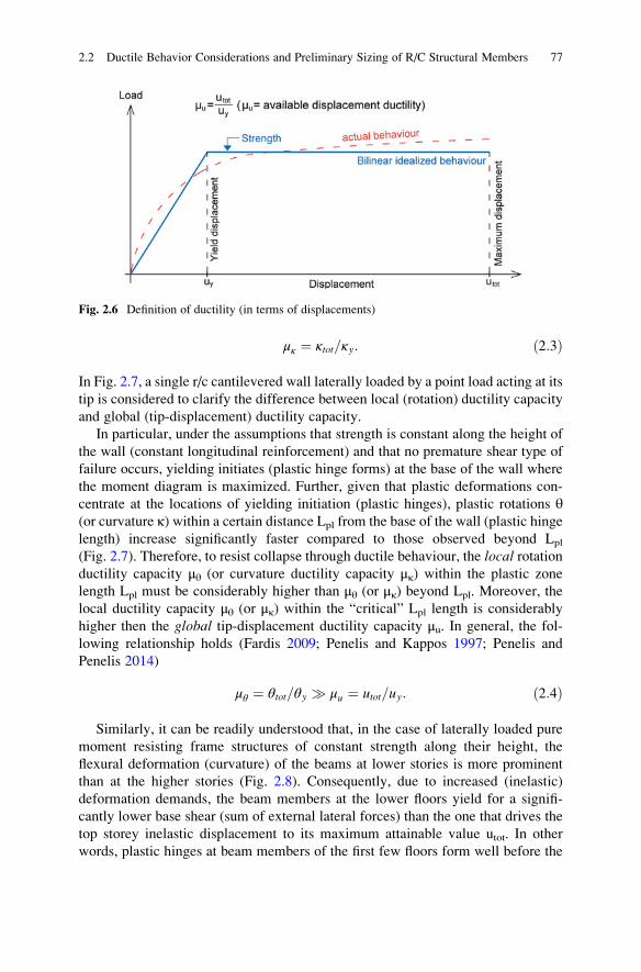
terms of displacement u (displacement ductility capacity μu) as the ratio of the peakattainable displacement value utot beyond which it is assumed that the structure
collapses over the yielding displacement uy signifying the onset of inelastic behav-
iour (Fig. 2.6). That is,
μu ¼ utot=uy: ð2:1Þ
The above definition applies for any type of displacement/deformation, including
the ductility capacity in terms of rotations θ (rotation ductility capacity)
μθ ¼ θtot=θy; ð2:2Þ
and the ductility capacity in terms of curvature κ (curvature ductility capacity):
76 2 Design of R/C Buildings to EC8-1: A Critical Overview
μκ ¼ κtot=κy: ð2:3Þ
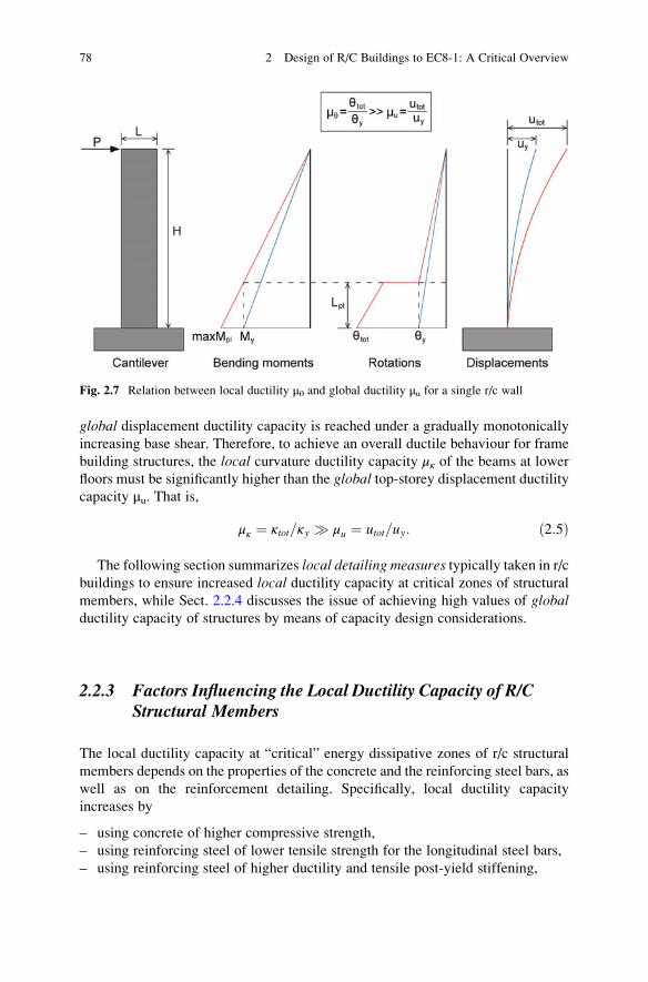
In Fig. 2.7, a single r/c cantilevered wall laterally loaded by a point load acting at its
tip is considered to clarify the difference between local (rotation) ductility capacity
and global (tip-displacement) ductility capacity.
In particular, under the assumptions that strength is constant along the height of
the wall (constant longitudinal reinforcement) and that no premature shear type of
failure occurs, yielding initiates (plastic hinge forms) at the base of the wall where
the moment diagram is maximized. Further, given that plastic deformations con-
centrate at the locations of yielding initiation (plastic hinges), plastic rotations θ(or curvature κ) within a certain distance Lpl from the base of the wall (plastic hinge
length) increase significantly faster compared to those observed beyond Lpl
(Fig. 2.7). Therefore, to resist collapse through ductile behaviour, the local rotationductility capacity μθ (or curvature ductility capacity μκ) within the plastic zone
length Lpl must be considerably higher than μθ (or μκ) beyond Lpl. Moreover, the
local ductility capacity μθ (or μκ) within the “critical” Lpl length is considerably
higher then the global tip-displacement ductility capacity μu. In general, the fol-
lowing relationship holds (Fardis 2009; Penelis and Kappos 1997; Penelis and
Penelis 2014)
μθ ¼ θtot=θy � μu ¼ utot=uy: ð2:4Þ
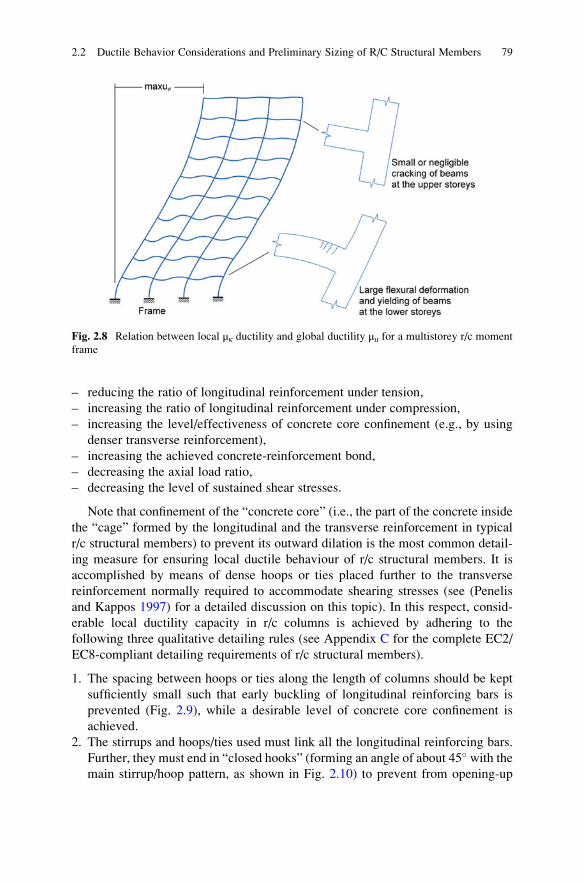
Similarly, it can be readily understood that, in the case of laterally loaded pure
moment resisting frame structures of constant strength along their height, the
flexural deformation (curvature) of the beams at lower stories is more prominent
than at the higher stories (Fig. 2.8). Consequently, due to increased (inelastic)
deformation demands, the beam members at the lower floors yield for a signifi-
cantly lower base shear (sum of external lateral forces) than the one that drives the
top storey inelastic displacement to its maximum attainable value utot. In other
words, plastic hinges at beam members of the first few floors form well before the
Fig. 2.6 Definition of ductility (in terms of displacements)
2.2 Ductile Behavior Considerations and Preliminary Sizing of R/C Structural Members 77
global displacement ductility capacity is reached under a gradually monotonically
increasing base shear. Therefore, to achieve an overall ductile behaviour for frame
building structures, the local curvature ductility capacity μκ of the beams at lower
floors must be significantly higher than the global top-storey displacement ductility
capacity μu. That is,
μκ ¼ κtot=κy � μu ¼ utot=uy: ð2:5Þ
The following section summarizes local detailing measures typically taken in r/cbuildings to ensure increased local ductility capacity at critical zones of structural
members, while Sect. 2.2.4 discusses the issue of achieving high values of globalductility capacity of structures by means of capacity design considerations.
2.2.3 Factors Influencing the Local Ductility Capacity of R/CStructural Members
The local ductility capacity at “critical” energy dissipative zones of r/c structural
members depends on the properties of the concrete and the reinforcing steel bars, as
well as on the reinforcement detailing. Specifically, local ductility capacity
increases by
– using concrete of higher compressive strength,
– using reinforcing steel of lower tensile strength for the longitudinal steel bars,
– using reinforcing steel of higher ductility and tensile post-yield stiffening,
Fig. 2.7 Relation between local ductility μθ and global ductility μu for a single r/c wall
78 2 Design of R/C Buildings to EC8-1: A Critical Overview
– reducing the ratio of longitudinal reinforcement under tension,
– increasing the ratio of longitudinal reinforcement under compression,
– increasing the level/effectiveness of concrete core confinement (e.g., by using
denser transverse reinforcement),
– increasing the achieved concrete-reinforcement bond,
– decreasing the axial load ratio,
– decreasing the level of sustained shear stresses.
Note that confinement of the “concrete core” (i.e., the part of the concrete inside
the “cage” formed by the longitudinal and the transverse reinforcement in typical
r/c structural members) to prevent its outward dilation is the most common detail-
ing measure for ensuring local ductile behaviour of r/c structural members. It is
accomplished by means of dense hoops or ties placed further to the transverse
reinforcement normally required to accommodate shearing stresses (see (Penelis
and Kappos 1997) for a detailed discussion on this topic). In this respect, consid-
erable local ductility capacity in r/c columns is achieved by adhering to the
following three qualitative detailing rules (see Appendix C for the complete EC2/
EC8-compliant detailing requirements of r/c structural members).
1. The spacing between hoops or ties along the length of columns should be kept
sufficiently small such that early buckling of longitudinal reinforcing bars is
prevented (Fig. 2.9), while a desirable level of concrete core confinement is
achieved.
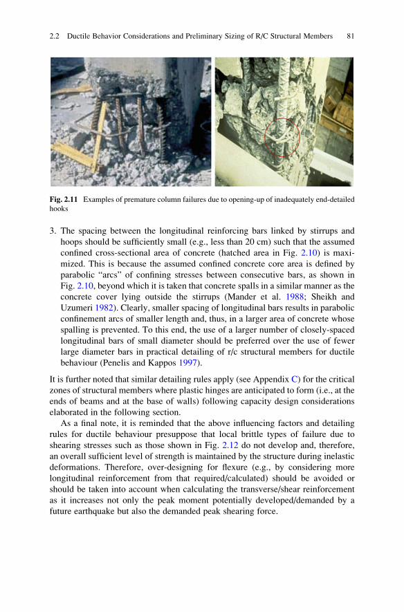
2. The stirrups and hoops/ties used must link all the longitudinal reinforcing bars.
Further, they must end in “closed hooks” (forming an angle of about 45� with themain stirrup/hoop pattern, as shown in Fig. 2.10) to prevent from opening-up
Fig. 2.8 Relation between local μκ ductility and global ductility μu for a multistorey r/c moment
frame
2.2 Ductile Behavior Considerations and Preliminary Sizing of R/C Structural Members 79
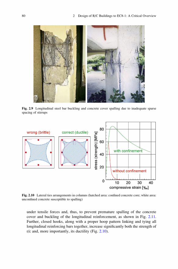
under tensile forces and, thus, to prevent premature spalling of the concrete
cover and buckling of the longitudinal reinforcement, as shown in Fig. 2.11.
Further, closed hooks, along with a proper hoop pattern linking and tying all
longitudinal reinforcing bars together, increase significantly both the strength of
r/c and, more importantly, its ductility (Fig. 2.10).
Fig. 2.9 Longitudinal steel bar buckling and concrete cover spalling due to inadequate sparse
spacing of stirrups
Fig. 2.10 Lateral ties arrangements in columns (hatched area: confined concrete core; white area:
unconfined concrete susceptible to spalling)
80 2 Design of R/C Buildings to EC8-1: A Critical Overview
3. The spacing between the longitudinal reinforcing bars linked by stirrups and
hoops should be sufficiently small (e.g., less than 20 cm) such that the assumed
confined cross-sectional area of concrete (hatched area in Fig. 2.10) is maxi-
mized. This is because the assumed confined concrete core area is defined by
parabolic “arcs” of confining stresses between consecutive bars, as shown in
Fig. 2.10, beyond which it is taken that concrete spalls in a similar manner as the
concrete cover lying outside the stirrups (Mander et al. 1988; Sheikh and
Uzumeri 1982). Clearly, smaller spacing of longitudinal bars results in parabolic
confinement arcs of smaller length and, thus, in a larger area of concrete whose
spalling is prevented. To this end, the use of a larger number of closely-spaced
longitudinal bars of small diameter should be preferred over the use of fewer
large diameter bars in practical detailing of r/c structural members for ductile
behaviour (Penelis and Kappos 1997).
It is further noted that similar detailing rules apply (see Appendix C) for the critical
zones of structural members where plastic hinges are anticipated to form (i.e., at the
ends of beams and at the base of walls) following capacity design considerations
elaborated in the following section.
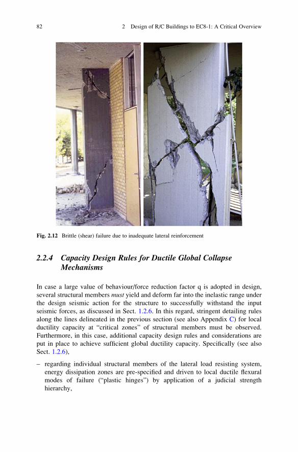
As a final note, it is reminded that the above influencing factors and detailing
rules for ductile behaviour presuppose that local brittle types of failure due to
shearing stresses such as those shown in Fig. 2.12 do not develop and, therefore,
an overall sufficient level of strength is maintained by the structure during inelastic
deformations. Therefore, over-designing for flexure (e.g., by considering more
longitudinal reinforcement from that required/calculated) should be avoided or
should be taken into account when calculating the transverse/shear reinforcement
as it increases not only the peak moment potentially developed/demanded by a
future earthquake but also the demanded peak shearing force.
Fig. 2.11 Examples of premature column failures due to opening-up of inadequately end-detailed
hooks
2.2 Ductile Behavior Considerations and Preliminary Sizing of R/C Structural Members 81
2.2.4 Capacity Design Rules for Ductile Global CollapseMechanisms
In case a large value of behaviour/force reduction factor q is adopted in design,
several structural members must yield and deform far into the inelastic range under
the design seismic action for the structure to successfully withstand the input
seismic forces, as discussed in Sect. 1.2.6. In this regard, stringent detailing rules
along the lines delineated in the previous section (see also Appendix C) for local
ductility capacity at “critical zones” of structural members must be observed.
Furthermore, in this case, additional capacity design rules and considerations are
put in place to achieve sufficient global ductility capacity. Specifically (see also
Sect. 1.2.6),
– regarding individual structural members of the lateral load resisting system,
energy dissipation zones are pre-specified and driven to local ductile flexural
modes of failure (“plastic hinges”) by application of a judicial strength
hierarchy,
Fig. 2.12 Brittle (shear) failure due to inadequate lateral reinforcement
82 2 Design of R/C Buildings to EC8-1: A Critical Overview
– regarding the lateral load resisting structural system as a whole, a certain
sequence of plastic hinges is pre-specified to maximize the dissipation of the
input seismic/kinetic energy via hysteretic behaviour prior to the development of
“desirable” plastic mechanisms.
The aforementioned energy dissipation zones are sized and detailed appropri-
ately to exhibit ductile behaviour. That is, to undergo large plastic deformations
under the design seismic action without losing a large part of their moment bearing
capacity. Cross sections of structural members outside the “critical” yielding zones,
and especially cross sections neighboring these critical zones, are strengthened to
ensure that they behave elastically upon plastic hinge formation.
Considering the development of plastic mechanisms, mechanisms that demand a
relatively small amount of seismic energy to be dissipated in order to develop must
be avoided. These are the mechanisms that require only a few plastic hinges to
form. The “desirable” collapse mechanisms are those that maximize the required
seismic energy dissipation in order to develop. Typically, these mechanisms require
a maximum total number of potential plastic hinges to form before the structure
collapses.
2.2.4.1 Plastic Mechanisms for Frame Lateral-Load Resisting Systems
In the case of pure moment resisting frame structural systems, two “extreme”
examples of plastic (collapse) mechanisms are depicted in Fig. 2.13. The “desir-
able” plastic mechanism commonly referred to as the “beam-sway mechanism” is
the one targeted via capacity design rules and requirements in code-compliant
seismic design. At the other end rests the “storey-sway mechanism” due to a soft
and/or weak storey which seismic codes of practice aim to avoid by relying on both
capacity design and conceptual design rules (see Sect. 2.1). A third type of
mechanism is shown in Fig. 2.15 called a “column-sway mechanism”, which is
also, theoretically, achievable but should be avoided for reasons discussed below.
Beam-sway mechanism
The desirable beam-sway plastic mechanism develops upon plastic hinge for-
mation at the ends of all beams and at the base of the columns of the ground storey.
As shown in Fig. 2.13, the required rotation θ1 at each one of the several plastic
hinges of the beam-sway mechanism is much smaller than the required rotation θ2at the few plastic hinges of the storey-sway mechanism for the same top-storey peak
displacement utot. Clearly, local ductility demands of the beam-sway mechanism
are significantly smaller. Furthermore, it is easier to accommodate ductility
demands of a beam-sway mechanism, since beams of typical building structures
carry negligible axial force compared to columns due to the diaphragmatic action of
floors. The low axial load level positively influences the local ductility capacity of
beams compared to that achieved by columns.
2.2 Ductile Behavior Considerations and Preliminary Sizing of R/C Structural Members 83
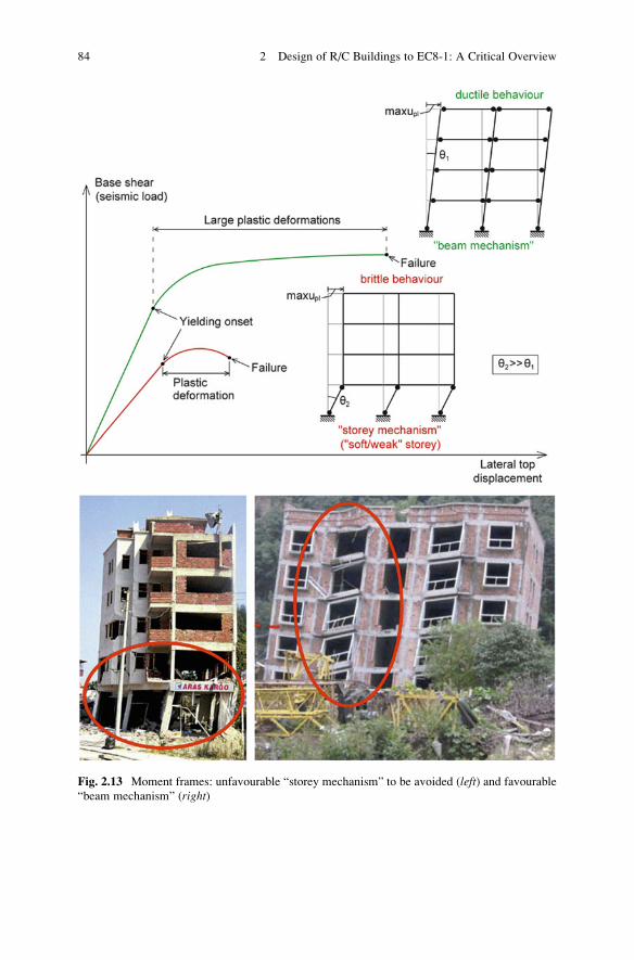
Fig. 2.13 Moment frames: unfavourable “storey mechanism” to be avoided (left) and favourable
“beam mechanism” (right)
84 2 Design of R/C Buildings to EC8-1: A Critical Overview
Nevertheless, it is pointed out that, in a beam-sway mechanism, the base of the
columns at the ground floor will eventually yield due to unavoidable high values of
locally developed moments. Therefore, it is recommended to increase the flexural
strength of the columns at the ground floor (beyond the strength required to
accommodate calculated moments from the structural analysis step) to “delay”
the formation of plastic hinges. Ideally, plastic hinges at the base of columns should
form last, upon yielding of all the beams.
Storey-sway mechanism
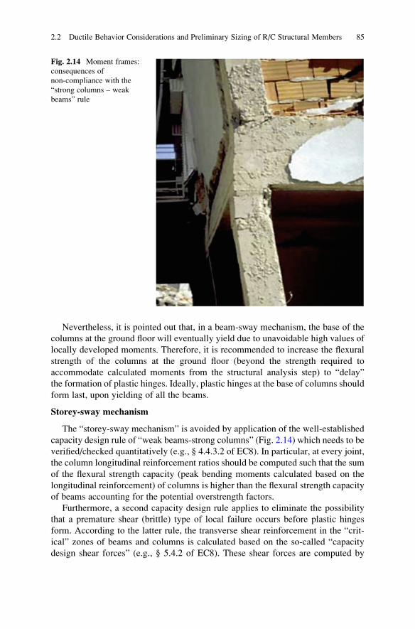
The “storey-sway mechanism” is avoided by application of the well-established
capacity design rule of “weak beams-strong columns” (Fig. 2.14) which needs to be
verified/checked quantitatively (e.g., § 4.4.3.2 of EC8). In particular, at every joint,
the column longitudinal reinforcement ratios should be computed such that the sum
of the flexural strength capacity (peak bending moments calculated based on the
longitudinal reinforcement) of columns is higher than the flexural strength capacity
of beams accounting for the potential overstrength factors.
Furthermore, a second capacity design rule applies to eliminate the possibility
that a premature shear (brittle) type of local failure occurs before plastic hinges
form. According to the latter rule, the transverse shear reinforcement in the “crit-
ical” zones of beams and columns is calculated based on the so-called “capacity
design shear forces” (e.g., § 5.4.2 of EC8). These shear forces are computed by
Fig. 2.14 Moment frames:
consequences of
non-compliance with the
“strong columns – weak
beams” rule
2.2 Ductile Behavior Considerations and Preliminary Sizing of R/C Structural Members 85
assuming that the ends of all beams and columns converging at any particular joint
have yielded accounting for the potential overstrength factors. Notably, the capacity
design shear forces are commonly considerably higher than the shear forces derived
from the structural analysis step. As a final note, it is emphasized that the develop-
ment of a storey-sway mechanism must be avoided not only for the ground storey as
shown in Fig. 2.13 for the sake of exemplification, but also for each and every
storey of the building.
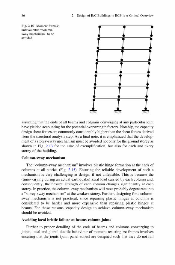
Column-sway mechanism
The “column-sway mechanism” involves plastic hinge formation at the ends of
columns at all stories (Fig. 2.15). Ensuring the reliable development of such a
mechanism is very challenging at design, if not unfeasible. This is because the
(time-varying during an actual earthquake) axial load carried by each column and,
consequently, the flexural strength of each column changes significantly at each
storey. In practice, the column-sway mechanism will most probably degenerate into
a “storey-sway mechanism” at the weakest storey. Further, designing for a column-
sway mechanism is not practical, since repairing plastic hinges at columns is
considered to be harder and more expensive than repairing plastic hinges at
beams. For these reasons, capacity design to achieve column-sway mechanism
should be avoided.
Avoiding local brittle failure at beams-column joints
Further to proper detailing of the ends of beams and columns converging to
joints, local and global ductile behaviour of moment resisting r/c frames involves
ensuring that the joints (joint panel zones) are designed such that they do not fail
Fig. 2.15 Moment frames:
unfavourable “column-
sway mechanism” to be
avoided
86 2 Design of R/C Buildings to EC8-1: A Critical Overview
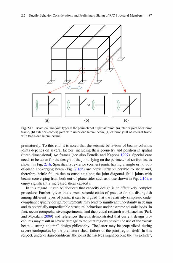
prematurely. To this end, it is noted that the seismic behaviour of beams-columns
joints depends on several factors, including their geometry and position in spatial
(three-dimensional) r/c frames (see also Penelis and Kappos 1997). Special care
needs to be taken for the design of the joints lying on the perimeter of r/c frames, as
shown in Fig. 2.16. Specifically, exterior (corner) joints having a single or no out-
of-plane converging beam (Fig. 2.16b) are particularly vulnerable to shear and,
therefore, brittle failure due to crushing along the joint diagonal. Still, joints with
beams converging from both out-of-plane sides such as those shown in Fig. 2.16a, c
enjoy significantly increased shear capacity.
In this regard, it can be deduced that capacity design is an effectively complex
procedure. Further, given that current seismic codes of practice do not distinguish
among different types of joints, it can be argued that the relatively simplistic code-
compliant capacity design requirements may lead to significant uncertainty in design
and to potentially unpredictable structural behaviour under extreme seismic loads. In
fact, recent comprehensive experimental and theoretical research work, such as (Park
and Mosalam 2009) and references therein, demonstrated that current design pro-
cedures may result in severe damage to the joint regions despite the use of the “weak
beam – strong column” design philosophy. The latter may be jeopardized during
severe earthquakes by the premature shear failure of the joint region itself. In this
respect, under certain conditions, the joints themselvesmight become the “weak link”,
Fig. 2.16 Beam-column joint types at the perimeter of a spatial frame: (a) interior joint of exteriorframe, (b) exterior (corner) joint with no or one lateral beam, (c) exterior joint of internal frame
with two-sided lateral beams
2.2 Ductile Behavior Considerations and Preliminary Sizing of R/C Structural Members 87
even in EC2- and EC8-compliant r/c structures (Tsonos 2007). To address this issue,
several procedures have been proposed in the literature, as reviewed in (Park and
Mosalam 2009) and (Penelis and Penelis 2014), to ensure that the initial formation of
plastic hinges as well as the subsequent extensive damage occurs at the ends of the
converging beam members, while columns and joints remain intact. It is envisioned
that such procedures will be incorporated into future versions of design codes to
achieve improved capacity design implementation.
2.2.4.2 Collapse Mechanisms for Dual Lateral-Load Resisting Systems
From a structural design viewpoint, pure frame lateral load resisting systems are not
recommended in high seismicity areas for more than three- or four-storey r/c
buildings. This is because rigid-jointed (moment resisting) frames are relatively
flexible and exhibit increased ductility/deformation demands under severe seismic
excitation, rendering them sensitive to second-order effects. Consequently, they
require careful local detailing during construction to achieve sufficient levels of
ductility capacity at critical zones which may not always be readily achievable in
practice. In this regard, it is usually preferable to choose lateral load-resisting
systems of increased stiffness and, thus, of reduced overall ductility/deformation
demands, by incorporation of r/c walls (Fintel 1991, 1995). As a rule of thumb, it is
generally easier in practice to construct a wall with sufficient flexural and shear
strength, rather than a ductile frame system.
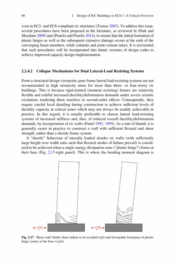
A “ductile” behaviour of laterally loaded slender r/c walls (with sufficiently
large height over width ratio such that flexural modes of failure prevail) is consid-
ered to be achieved when a single energy dissipation zone (“plastic hinge”) forms at
their base (Fig. 2.17-right panel). This is where the bending moment diagram is
Fig. 2.17 Shear wall: brittle shear failure to be avoided (left) and favourable formation of plastic
hinge (zone) at the base (right)
88 2 Design of R/C Buildings to EC8-1: A Critical Overview
maximized in typical slender walls. Moreover, walls should remain elastic along
the rest of their height.
This desired behaviour is assured by observing the following two capacity
design rules for ductile r/c walls (e.g., § 5.4.2.4 of EC8).
– Shear and flexural types of failure at storey levels above the ground storey must
be avoided. This is achieved by designing/detailing the cross-sections of walls
above the ground storey for higher shear and flexural strength capacity than
those required from the structural analysis step.
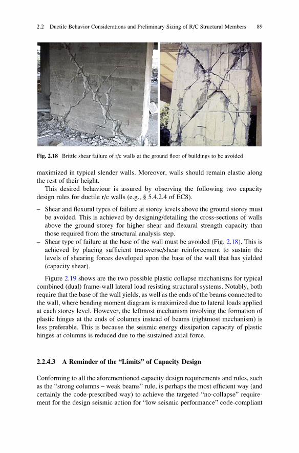
– Shear type of failure at the base of the wall must be avoided (Fig. 2.18). This is
achieved by placing sufficient transverse/shear reinforcement to sustain the
levels of shearing forces developed upon the base of the wall that has yielded
(capacity shear).
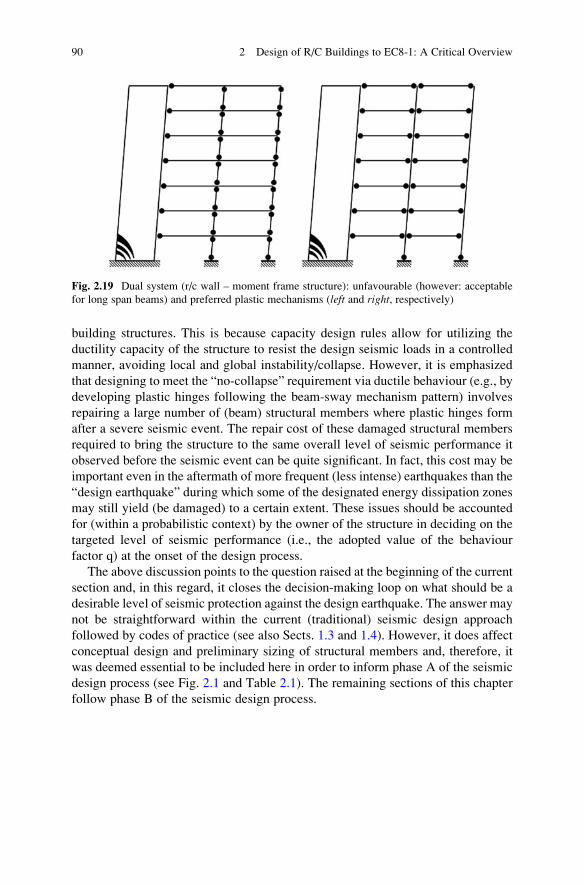
Figure 2.19 shows are the two possible plastic collapse mechanisms for typical
combined (dual) frame-wall lateral load resisting structural systems. Notably, both
require that the base of the wall yields, as well as the ends of the beams connected to
the wall, where bending moment diagram is maximized due to lateral loads applied
at each storey level. However, the leftmost mechanism involving the formation of
plastic hinges at the ends of columns instead of beams (rightmost mechanism) is
less preferable. This is because the seismic energy dissipation capacity of plastic
hinges at columns is reduced due to the sustained axial force.
2.2.4.3 A Reminder of the “Limits” of Capacity Design
Conforming to all the aforementioned capacity design requirements and rules, such
as the “strong columns – weak beams” rule, is perhaps the most efficient way (and
certainly the code-prescribed way) to achieve the targeted “no-collapse” require-
ment for the design seismic action for “low seismic performance” code-compliant
Fig. 2.18 Brittle shear failure of r/c walls at the ground floor of buildings to be avoided
2.2 Ductile Behavior Considerations and Preliminary Sizing of R/C Structural Members 89
building structures. This is because capacity design rules allow for utilizing the
ductility capacity of the structure to resist the design seismic loads in a controlled
manner, avoiding local and global instability/collapse. However, it is emphasized
that designing to meet the “no-collapse” requirement via ductile behaviour (e.g., by
developing plastic hinges following the beam-sway mechanism pattern) involves
repairing a large number of (beam) structural members where plastic hinges form
after a severe seismic event. The repair cost of these damaged structural members
required to bring the structure to the same overall level of seismic performance it
observed before the seismic event can be quite significant. In fact, this cost may be
important even in the aftermath of more frequent (less intense) earthquakes than the
“design earthquake” during which some of the designated energy dissipation zones
may still yield (be damaged) to a certain extent. These issues should be accounted
for (within a probabilistic context) by the owner of the structure in deciding on the
targeted level of seismic performance (i.e., the adopted value of the behaviour
factor q) at the onset of the design process.
The above discussion points to the question raised at the beginning of the current
section and, in this regard, it closes the decision-making loop on what should be a
desirable level of seismic protection against the design earthquake. The answer may
not be straightforward within the current (traditional) seismic design approach
followed by codes of practice (see also Sects. 1.3 and 1.4). However, it does affect
conceptual design and preliminary sizing of structural members and, therefore, it
was deemed essential to be included here in order to inform phase A of the seismic
design process (see Fig. 2.1 and Table 2.1). The remaining sections of this chapter
follow phase B of the seismic design process.
Fig. 2.19 Dual system (r/c wall – moment frame structure): unfavourable (however: acceptable
for long span beams) and preferred plastic mechanisms (left and right, respectively)
90 2 Design of R/C Buildings to EC8-1: A Critical Overview
2.3 Structural and Loading Modeling for Seismic Designof R/C Buildings Using Linear Analysis Methods
Upon completion of the conceptual design phase during which the preliminary
sizing of structural members takes place, the seismic design process proceeds with
the analysis phase. The first stage of the analysis phase involves the development of
the mathematical or computational model of the building structure to be used in the
next, structural analysis stage. Routine “modeling” of ordinary building structures
for seismic design includes:
– defining the design seismic loading combination comprising the design seismic
action and the permanent, plus a fraction of variable gravitational loads; and
– developing a numerical finite element (FE) model which can adequately serve
the purpose of determining the seismic effects (deformations and stress resul-
tants) for the detailing of the load resisting system of the building structure.
Section 2.3.1 discusses several important issues arising in defining the
EC8-compliant design seismic action. Section 2.3.2 presents the general structural
modeling requirements prescribed by EC8. Lastly, Sect. 2.3.3 provides guidance
and practical recommendations for the development of adequate FE models to be
adopted in the context of routine seismic design of multistorey r/c buildings
according to EC8, using linear methods of analysis.
2.3.1 EC8-Compliant Loading Modeling for Seismic Design
In the context of EC8-compliant force-based seismic design, equivalent linear types
of analysis are routinely employed in which the design seismic action is defined by
means of an inelastic pseudo-acceleration spectrum (see also Sect. 1.2.4). This
spectrum is termed the “design spectrum for elastic analysis” in clause §3.2.2.5 of
EC8, hereafter the design spectrum. It attains reduced ordinates compared to the
elastic pseudo-acceleration response spectrum (termed the “horizontal elastic spec-trum” in clause §3.2.2.2 of EC8) depending on the assumed behaviour (or force
reduction) factor q. The lateral seismic design base shear is proportional to the
design spectrum ordinates and to the inertial/mass properties of the structure.
Therefore, lateral seismic loads are determined by means of the design spectrum
and the nominal gravitational loading combination (gravitational permanent plus
variable actions according to Eurocode 0 (CEN 2002) from which the inertial
properties of the structure can be derived and accounted for in the analysis stage.
The thus defined seismic loads are further combined with the nominal gravitational
loading combination acting simultaneously with the lateral seismic loads. In the
case of buildings with structural members susceptible to undue local vertical
vibrations (e.g., horizontal cantilevered structural members or beam supporting
columns; see §4.3.3.5.2 of EC8), the vertical component of the ground motion
2.3 Structural and Loading Modeling for Seismic Design of R/C Buildings Using. . . 91
needs to be accounted for as well, yielding additional seismic loads in the vertical
(gravitational) direction (§3.2.2.3 of EC8). Finally, the EC8-prescribed loading
modeling for seismic design is complemented by certain additional considerations,
such as the site seismic hazard from which the “design seismic action” is specified
and the assumed directions along which the seismic action is applied.
In general, EC8, complemented by the National Annexes and Eurocode 0 (CEN
2002), describes most aspects of the seismic loading modeling with sufficient
clarity for practitioners to follow. Therefore, the following paragraphs of this
section provide only brief comments on certain issues related to (i) the definition
of the design seismic action in terms of peak ground acceleration within a proba-
bilistic context, (ii) the EC8 design spectrum, (iii) the relation between the design
peak ground acceleration and the behaviour factor q, and (iv) the EC8 prescribed
inertial structural properties for seismic design and the seismic loading combina-
tion. Other aspects of loading modeling (e.g., direction of seismic action, in plan
points of action for the lateral seismic loads in the lateral force method, etc.) are
discussed in subsequent sections and chapters focusing on the EC8 prescribed linear
analysis methods and their practical implementation (Kappos 2002).
2.3.1.1 Reference Seismic Action αgR, Design Seismic Action αg and,
Importance Factor γI
According to clause §2.1(1)P of EC8, the “reference” level of the seismic intensity
for the no-collapse requirement is defined in terms of the peak (horizontal) groundacceleration value αgR recorded on rock and having a return period ΤR of 475 years
(denoted by TNCR), or a probability PR of 10 % (denoted by PNCR) to be exceeded
within a time period te (“exposure time”) equal to 50 years (see also Sect. 1.1.4).
Further, for the damage limitation requirement, a reduced seismic action is taken,
represented by a peak ground acceleration value with a return period TDLR equal to
95 years, or a probability PDLR of 10 % to be exceeded in 10 years.
The above correspondence between the return period TR and the probability PRrelies on modeling the occurrence of an earthquake within a time interval as a
discrete random variable following the Poisson distribution. In particular, the
Poisson model involves the following three assumptions:
– the number of earthquake events in one time interval is independent of the
number of earthquake events in any other past or future time interval;
– the probability of an earthquake event in a short time interval is proportional to
the duration of this time interval; and
– the probability of observing more than one earthquake event during a short time
interval is negligible.
Under the above assumptions, it can be shown that the probability PR that a certain
value of ground acceleration αg will be exceeded within a given “exposure time” tein years (note that EC8 uses the symbol TL to denote exposure) is expressed by
92 2 Design of R/C Buildings to EC8-1: A Critical Overview
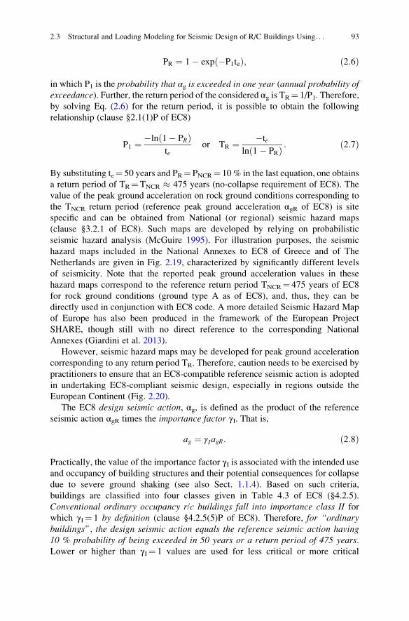
PR ¼ 1� exp �P1teð Þ; ð2:6Þ
in which P1 is the probability that αg is exceeded in one year (annual probability ofexceedance). Further, the return period of the considered αg is TR¼ 1/P1. Therefore,
by solving Eq. (2.6) for the return period, it is possible to obtain the following
relationship (clause §2.1(1)P of EC8)
P1 ¼ �ln 1� PRð Þte
or TR ¼ �te
ln 1� PRð Þ : ð2:7Þ
By substituting te¼ 50 years and PR¼ PNCR¼ 10 % in the last equation, one obtains
a return period of TR¼TNCR � 475 years (no-collapse requirement of EC8). The
value of the peak ground acceleration on rock ground conditions corresponding to
the TNCR return period (reference peak ground acceleration αgR of EC8) is site
specific and can be obtained from National (or regional) seismic hazard maps
(clause §3.2.1 of EC8). Such maps are developed by relying on probabilistic
seismic hazard analysis (McGuire 1995). For illustration purposes, the seismic
hazard maps included in the National Annexes to EC8 of Greece and of The
Netherlands are given in Fig. 2.19, characterized by significantly different levels
of seismicity. Note that the reported peak ground acceleration values in these
hazard maps correspond to the reference return period TNCR¼ 475 years of EC8
for rock ground conditions (ground type A as of EC8), and, thus, they can be
directly used in conjunction with EC8 code. A more detailed Seismic Hazard Map
of Europe has also been produced in the framework of the European Project
SHARE, though still with no direct reference to the corresponding National
Annexes (Giardini et al. 2013).
However, seismic hazard maps may be developed for peak ground acceleration
corresponding to any return period TR. Therefore, caution needs to be exercised by
practitioners to ensure that an EC8-compatible reference seismic action is adopted
in undertaking EC8-compliant seismic design, especially in regions outside the
European Continent (Fig. 2.20).
The EC8 design seismic action, αg, is defined as the product of the reference
seismic action αgR times the importance factor γI. That is,
ag ¼ γIagR: ð2:8Þ
Practically, the value of the importance factor γI is associated with the intended useand occupancy of building structures and their potential consequences for collapse
due to severe ground shaking (see also Sect. 1.1.4). Based on such criteria,
buildings are classified into four classes given in Table 4.3 of EC8 (§4.2.5).
Conventional ordinary occupancy r/c buildings fall into importance class II forwhich γI¼ 1 by definition (clause §4.2.5(5)P of EC8). Therefore, for “ordinarybuildings”, the design seismic action equals the reference seismic action having10 % probability of being exceeded in 50 years or a return period of 475 years.Lower or higher than γI¼ 1 values are used for less critical or more critical
2.3 Structural and Loading Modeling for Seismic Design of R/C Buildings Using. . . 93
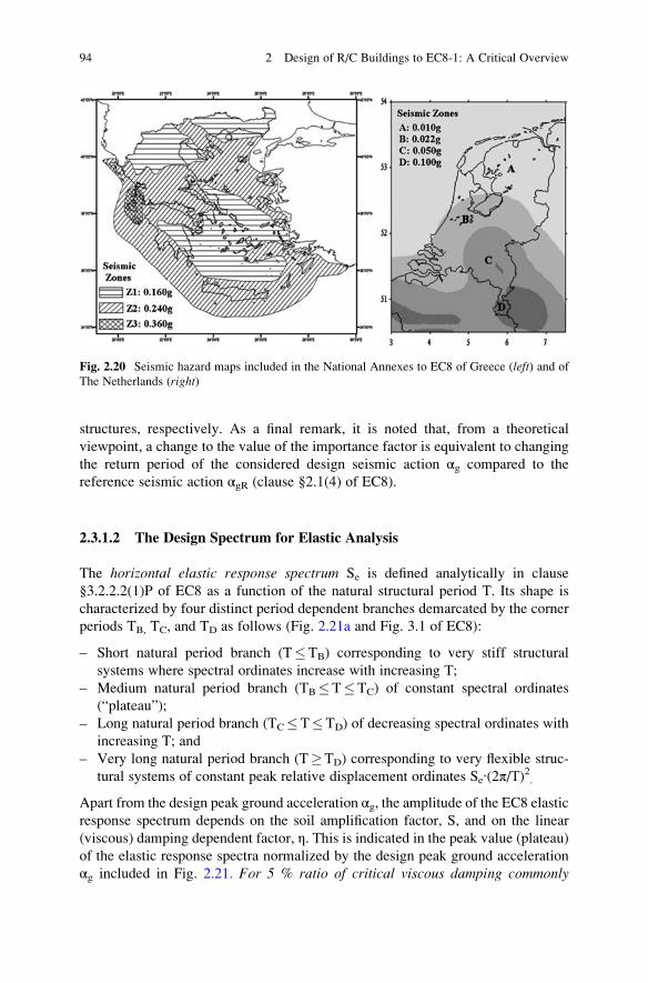
structures, respectively. As a final remark, it is noted that, from a theoretical
viewpoint, a change to the value of the importance factor is equivalent to changing
the return period of the considered design seismic action αg compared to the
reference seismic action αgR (clause §2.1(4) of EC8).
2.3.1.2 The Design Spectrum for Elastic Analysis
The horizontal elastic response spectrum Se is defined analytically in clause
§3.2.2.2(1)P of EC8 as a function of the natural structural period T. Its shape is
characterized by four distinct period dependent branches demarcated by the corner
periods TB, TC, and TD as follows (Fig. 2.21a and Fig. 3.1 of EC8):
– Short natural period branch (T�TB) corresponding to very stiff structural
systems where spectral ordinates increase with increasing T;
– Medium natural period branch (TB�T�TC) of constant spectral ordinates
(“plateau”);
– Long natural period branch (TC�T�TD) of decreasing spectral ordinates with
increasing T; and
– Very long natural period branch (T�TD) corresponding to very flexible struc-
tural systems of constant peak relative displacement ordinates Se∙(2π/Τ)2.
Apart from the design peak ground acceleration αg, the amplitude of the EC8 elastic
response spectrum depends on the soil amplification factor, S, and on the linear
(viscous) damping dependent factor, η. This is indicated in the peak value (plateau)of the elastic response spectra normalized by the design peak ground acceleration
αg included in Fig. 2.21. For 5 % ratio of critical viscous damping commonly
Fig. 2.20 Seismic hazard maps included in the National Annexes to EC8 of Greece (left) and of
The Netherlands (right)
94 2 Design of R/C Buildings to EC8-1: A Critical Overview
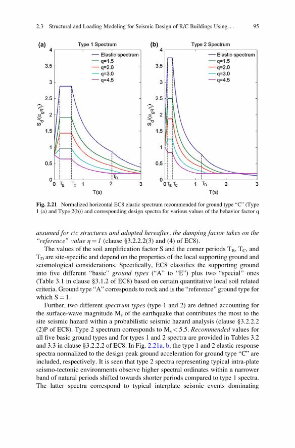
assumed for r/c structures and adopted hereafter, the damping factor takes on the“reference” value η¼ 1 (clause §3.2.2.2(3) and (4) of EC8).
The values of the soil amplification factor S and the corner periods TB, TC, and
TD are site-specific and depend on the properties of the local supporting ground and
seismological considerations. Specifically, EC8 classifies the supporting ground
into five different “basic” ground types (“A” to “E”) plus two “special” ones
(Table 3.1 in clause §3.1.2 of EC8) based on certain quantitative local soil related
criteria. Ground type “A” corresponds to rock and is the “reference” ground type for
which S¼ 1.
Further, two different spectrum types (type 1 and 2) are defined accounting for
the surface-wave magnitude Ms of the earthquake that contributes the most to the
site seismic hazard within a probabilistic seismic hazard analysis (clause §3.2.2.2
(2)P of EC8). Type 2 spectrum corresponds to Ms< 5.5. Recommended values for
all five basic ground types and for types 1 and 2 spectra are provided in Tables 3.2
and 3.3 in clause §3.2.2.2 of EC8. In Fig. 2.21a, b, the type 1 and 2 elastic response
spectra normalized to the design peak ground acceleration for ground type “C” are
included, respectively. It is seen that type 2 spectra representing typical intra-plate
seismo-tectonic environments observe higher spectral ordinates within a narrower
band of natural periods shifted towards shorter periods compared to type 1 spectra.
The latter spectra correspond to typical interplate seismic events dominating
Fig. 2.21 Normalized horizontal EC8 elastic spectrum recommended for ground type “C” (Type
1 (a) and Type 2(b)) and corresponding design spectra for various values of the behavior factor q
2.3 Structural and Loading Modeling for Seismic Design of R/C Buildings Using. . . 95
seismic structural design in most regions of South Eastern European countries (e.g.,
Italy, Greece, Turkey) and many other high seismicity areas worldwide.
The EC8 design spectrum for elastic analysis Sd is analytically expressed as
(§3.2.2.5 of EC8)
Sd Tð Þ ¼
γIαgRS2
3þ T
TB
2:5
q� 2
3
� �� �, 0 � T � TB
γIαgRS2:5
q, TB � T � TC
γIαgRS2:5
q
TC
T
� �� βγIαgR, TC � T � TD
γIαgRS2:5
q
TCTD
T2
� �� βγIαgR, TD � T
8>>>>>>>>>><>>>>>>>>>>:
; ð2:9Þ
where:
– γIαgR (¼αg) is the peak (horizontal) ground acceleration corresponding to the
design seismic action (for importance factor γI¼ 1, the value of αg has 10 %
probability of being exceeded in 50 years, as discussed in Sect. 2.3.1.1);
– S is the soil amplification factor (reference value S¼ 1 for rock ground “A”);
– TB and TC are the corner periods defining the second constant acceleration
branch (“plateau”) of the design spectrum;
– TD is the corner period signifying the beginning of the constant peak relative
displacement (Sd(2π/Τ)2) response range;– β denotes a lower bound for the design spectrum normalized by αg, having a
recommended value of 0.20 and
– q is the behaviour (or force reduction) factor (see Sect. 1.2.2).
The EC8 design spectrum Sd in Eq. (2.9) is a piecewise continuous function of T
obtained by dividing the three branches of the elastic spectrum Se for T�TB by the
behaviour factor q and by reducing the theoretical “zero period” spectral ordinate
Se(T¼ 0) by 2/3. Additionally, a minimum bound is applied to the two right-most
branches along the natural period axis.
Therefore, by setting q¼ 1 and by replacing the 2/3 ratio of the first branch in
Eq. (2.9) by 1, one retrieves the EC8 elastic response spectrum for 5 % damping.
This is further illustrated in Fig. 2.21 where four EC8 design spectra obtained by the
type 1 and type 2 elastic response spectra for ground “C” are plotted for four values
of the behaviour factor q. Note that these design spectra are “pinned” at a Sd(T¼ 0)/
αg¼ 2/3∙Se(T¼ 0)/αg value which remains the same for any behaviour factor. In
fact, for large behaviour factors, the first branch of the design spectrum may have a
negative slope (decreasing spectral ordinates with increasing natural period) which
is never the case for the elastic response spectrum. It is further noted that a lower
bound of β¼ 0.2 applies for very long natural periods.
The significance of the behaviour factor q in code-compliant seismic design has
been highlighted in Sect. 1.4 and further comments and recommendations are
96 2 Design of R/C Buildings to EC8-1: A Critical Overview
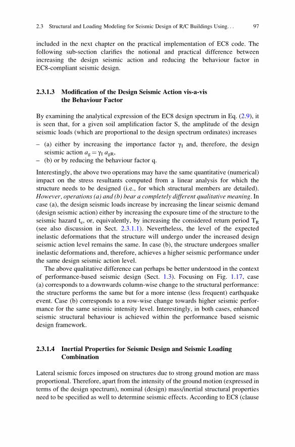
included in the next chapter on the practical implementation of EC8 code. The
following sub-section clarifies the notional and practical difference between
increasing the design seismic action and reducing the behaviour factor in
EC8-compliant seismic design.
2.3.1.3 Modification of the Design Seismic Action vis-a-vis
the Behaviour Factor
By examining the analytical expression of the EC8 design spectrum in Eq. (2.9), it
is seen that, for a given soil amplification factor S, the amplitude of the design
seismic loads (which are proportional to the design spectrum ordinates) increases
– (a) either by increasing the importance factor γI and, therefore, the design
seismic action ag¼ γI agR,– (b) or by reducing the behaviour factor q.
Interestingly, the above two operations may have the same quantitative (numerical)
impact on the stress resultants computed from a linear analysis for which the
structure needs to be designed (i.e., for which structural members are detailed).
However, operations (a) and (b) bear a completely different qualitative meaning. Incase (a), the design seismic loads increase by increasing the linear seismic demand
(design seismic action) either by increasing the exposure time of the structure to the
seismic hazard te, or, equivalently, by increasing the considered return period TR
(see also discussion in Sect. 2.3.1.1). Nevertheless, the level of the expected
inelastic deformations that the structure will undergo under the increased design
seismic action level remains the same. In case (b), the structure undergoes smaller
inelastic deformations and, therefore, achieves a higher seismic performance under
the same design seismic action level.
The above qualitative difference can perhaps be better understood in the context
of performance-based seismic design (Sect. 1.3). Focusing on Fig. 1.17, case
(a) corresponds to a downwards column-wise change to the structural performance:
the structure performs the same but for a more intense (less frequent) earthquake
event. Case (b) corresponds to a row-wise change towards higher seismic perfor-
mance for the same seismic intensity level. Interestingly, in both cases, enhanced
seismic structural behaviour is achieved within the performance based seismic
design framework.
2.3.1.4 Inertial Properties for Seismic Design and Seismic Loading
Combination
Lateral seismic forces imposed on structures due to strong ground motion are mass
proportional. Therefore, apart from the intensity of the ground motion (expressed in
terms of the design spectrum), nominal (design) mass/inertial structural properties
need to be specified as well to determine seismic effects. According to EC8 (clause
2.3 Structural and Loading Modeling for Seismic Design of R/C Buildings Using. . . 97
§3.2.4), the mass/inertial properties for seismic design are obtained by considering
the characteristic value Gk of all j permanent gravity loads (e.g., self-weight of
structural and permanent non-structural elements, fixed equipment, finishing, etc.),
but only a fraction of the characteristic value Qk of all i variable gravity loads (e.g.,
loads due to occupancy, movable equipment, etc.) in the following combination of
actions:
Xj
Gk, j
� �“þ ”
Xi
ψE, iQk, i� �
; ð2:10Þ
where the symbolXk
implies “the combined effect of all k actions” and the symbol
“+” implies “to be combined with” following the standard notation adopted within
the Eurocode series. In the above expression, ψE,i is a combination coefficient for
variable action i given as (clause §4.2.4 of EC8)
ψE, i ¼ φψ2i; ð2:11Þ
where, ψ2i is the combination coefficient of the quasi-permanent value of the i
variable action, ψ2iQk,i, and φ� 1 is a coefficient that may further reduce the quasi-
permanent value of variable action depending on the type of variable action and the
storey occupancy in a building structure.
The combination coefficients ψ2i are given in Eurocode 0 (CEN 2002) Annex
A1, and may be as low as 0.3 for ordinary occupancy residential and office
buildings recognizing that, during an earthquake, a relatively small fraction of the
characteristic value of the variable actions will be acting combined with the action
of the full permanent loads. In fact, the quasi-permanent value of a variable action
ψ2Qk is considered to be “almost always” exceeded during the life-time of a
structure within a probabilistic/statistical context. Moreover, recommended values
for the φ coefficient are included in Table 4.2 of EC8 (§4.2.4) which can be as low
as 0.5 allowing for up to 50 % reduction of the considered mass of the building
contributed by the quasi-permanent gravity variable loads.
As a closure to this section, it is deemed essential to note that the seismic action
is classified as an “accidental” action to Eurocode 0 (CEN 2002) and that the “total”
design action combination, which includes permanent and variable actions together
with the seismic action, is given by (clause §6.4.3.4 of EN1990:2002)
Xj
Gk, j
� �“þ ”P“þ ”AED “þ ”
Xi
ψ2, iQk, i� �
; ð2:12Þ
in which AED is the design seismic (accidental) action and P denotes the
prestressing action, if it exists. In view of Eqs. (2.10), (2.11), and (2.12), it is
important to note that the φ enters only in the definition of the gravity loads used to
obtain the inertia property of the building structure and therefore influences the
value of AED. However, it is not used in combining the quasi-permanent variable
98 2 Design of R/C Buildings to EC8-1: A Critical Overview
actions in the total seismic loading combination of Eq. (2.12). In other words, if
φ 6¼ 1 is adopted, the mass of the building used to define the design seismic action
AED will not be consistent with the gravity loads applied to the structure in
combination with the design seismic action in the analysis stage.
2.3.2 EC8-Compliant Modeling of Superstructure,Foundation, and Supporting Ground
The gravity and lateral load-resisting (or load-bearing) structural system of r/c
building structures comprises the superstructure and the foundation. Its mission is
to safely transfer externally applied loads (e.g., gravity loads primarily applied to
floor slabs, lateral loads due to wind pressure, lateral inertial loads due to horizontal
seismic excitations, etc.) to the supporting ground. Apart from floor slabs, thesuperstructure of a typical contemporary r/c building designed for earthquake
resistance can include beams, columns, walls, and cores, as schematically shown
in Fig. 2.22. Further, the foundation system may include simple pad footings, stripfootings, deep beam grillages, or even monolithic mat-slab (raft) foundations to
support the vertical structural members (columns, walls, and cores).
One-dimensional finite elements (e.g., two-node Euler-Bernoulli beam/column
element) and sometimes two-dimensional finite elements (e.g., four-node rectangu-lar shell elements for plate bending or plane stress) together with appropriate finiteelement meshing schemes are routinely incorporated to represent the material,
structural, and inertial properties of the above structural members and to define
their topology and connectivity in typical numerical/computational finite element(FE) models. Furthermore, for the case of ordinary r/c building structures subject to
seismic excitation, soil compliance can be accounted for, if deemed necessary, by
FE models by introducing elastic support conditions at the foundation level. More
sophisticated numerical/modeling techniques for capturing explicitly the dynamic
soil-foundation-structure interaction phenomenon (e.g., use of two-dimensional/
three dimensional finite elements or boundary elements to model the supporting
ground) are rarely considered in the seismic design of structures concerned in this
book and, thus, are left out of the ensuing discussions.
Focusing on the superstructure FE modeling of a typical r/c building, a better
insight into the involved considerations and requirements can be gained by exam-
ining structural members and structural sub-systems on an individual basis. In a
nutshell, beams are horizontally oriented and exhibit primarily uni-directional
flexural behaviour along the vertical (gravitational) plane due to vertical and lateral
loads. Due to their orientation and monolithic connection with the floor slabs,
beams bear negligible loads along their longitudinal direction (axial loads). Further,
they are taken to have flanged cross-sections, either T-shaped or L-shaped.
On the antipode, columns bear significant axial loads, since they are vertically
oriented, and undergo significant bi-directional flexure under seismic excitation.
2.3 Structural and Loading Modeling for Seismic Design of R/C Buildings Using. . . 99
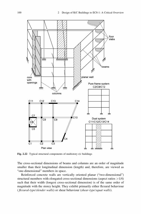
The cross-sectional dimensions of beams and columns are an order of magnitude
smaller than their longitudinal dimension (length) and, therefore, are viewed as
“one-dimensional” members in space.
Reinforced concrete walls are vertically oriented planar (“two-dimensional”)
structural members with elongated cross-sectional dimensions (aspect ratios >1/4)
such that their width (longest cross-sectional dimension) is of the same order of
magnitude with the storey height. They exhibit primarily either flexural behaviour
( flexural-type/slender walls) or shear behaviour (shear-type/squat walls).
Fig. 2.22 Typical structural components of multistory r/c buildings
100 2 Design of R/C Buildings to EC8-1: A Critical Overview
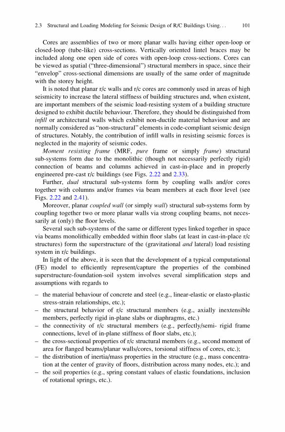
Cores are assemblies of two or more planar walls having either open-loop or
closed-loop (tube-like) cross-sections. Vertically oriented lintel braces may be
included along one open side of cores with open-loop cross-sections. Cores can
be viewed as spatial (“three-dimensional”) structural members in space, since their
“envelop” cross-sectional dimensions are usually of the same order of magnitude
with the storey height.
It is noted that planar r/c walls and r/c cores are commonly used in areas of high
seismicity to increase the lateral stiffness of building structures and, when existent,
are important members of the seismic load-resisting system of a building structure
designed to exhibit ductile behaviour. Therefore, they should be distinguished from
infill or architectural walls which exhibit non-ductile material behaviour and are
normally considered as “non-structural” elements in code-compliant seismic design
of structures. Notably, the contribution of infill walls in resisting seismic forces is
neglected in the majority of seismic codes.
Moment resisting frame (MRF, pure frame or simply frame) structural
sub-systems form due to the monolithic (though not necessarily perfectly rigid)
connection of beams and columns achieved in cast-in-place and in properly
engineered pre-cast r/c buildings (see Figs. 2.22 and 2.33).
Further, dual structural sub-systems form by coupling walls and/or cores
together with columns and/or frames via beam members at each floor level (see
Figs. 2.22 and 2.41).
Moreover, planar coupled wall (or simply wall) structural sub-systems form by
coupling together two or more planar walls via strong coupling beams, not neces-
sarily at (only) the floor levels.
Several such sub-systems of the same or different types linked together in space
via beams monolithically embedded within floor slabs (at least in cast-in-place r/c
structures) form the superstructure of the (gravitational and lateral) load resisting
system in r/c buildings.
In light of the above, it is seen that the development of a typical computational
(FE) model to efficiently represent/capture the properties of the combined
superstructure-foundation-soil system involves several simplification steps and
assumptions with regards to
– the material behaviour of concrete and steel (e.g., linear-elastic or elasto-plastic
stress-strain relationships, etc.);
– the structural behavior of r/c structural members (e.g., axially inextensible
members, perfectly rigid in-plane slabs or diaphragms, etc.)
– the connectivity of r/c structural members (e.g., perfectly/semi- rigid frame
connections, level of in-plane stiffness of floor slabs, etc.);
– the cross-sectional properties of r/c structural members (e.g., second moment of
area for flanged beams/planar walls/cores, torsional stiffness of cores, etc.);
– the distribution of inertia/mass properties in the structure (e.g., mass concentra-
tion at the center of gravity of floors, distribution across many nodes, etc.); and
– the soil properties (e.g., spring constant values of elastic foundations, inclusion
of rotational springs, etc.).
2.3 Structural and Loading Modeling for Seismic Design of R/C Buildings Using. . . 101
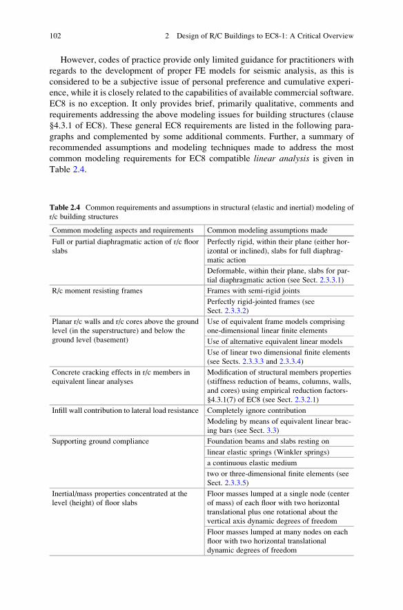
However, codes of practice provide only limited guidance for practitioners with
regards to the development of proper FE models for seismic analysis, as this is
considered to be a subjective issue of personal preference and cumulative experi-
ence, while it is closely related to the capabilities of available commercial software.
EC8 is no exception. It only provides brief, primarily qualitative, comments and
requirements addressing the above modeling issues for building structures (clause
§4.3.1 of EC8). These general EC8 requirements are listed in the following para-
graphs and complemented by some additional comments. Further, a summary of
recommended assumptions and modeling techniques made to address the most
common modeling requirements for EC8 compatible linear analysis is given in
Table 2.4.
Table 2.4 Common requirements and assumptions in structural (elastic and inertial) modeling of
r/c building structures
Common modeling aspects and requirements Common modeling assumptions made
Full or partial diaphragmatic action of r/c floor
slabs
Perfectly rigid, within their plane (either hor-
izontal or inclined), slabs for full diaphrag-
matic action
Deformable, within their plane, slabs for par-
tial diaphragmatic action (see Sect. 2.3.3.1)
R/c moment resisting frames Frames with semi-rigid joints
Perfectly rigid-jointed frames (see
Sect. 2.3.3.2)
Planar r/c walls and r/c cores above the ground
level (in the superstructure) and below the
ground level (basement)
Use of equivalent frame models comprising
one-dimensional linear finite elements
Use of alternative equivalent linear models
Use of linear two dimensional finite elements
(see Sects. 2.3.3.3 and 2.3.3.4)
Concrete cracking effects in r/c members in
equivalent linear analyses
Modification of structural members properties
(stiffness reduction of beams, columns, walls,
and cores) using empirical reduction factors-
§4.3.1(7) of EC8 (see Sect. 2.3.2.1)
Infill wall contribution to lateral load resistance Completely ignore contribution
Modeling by means of equivalent linear brac-
ing bars (see Sect. 3.3)
Supporting ground compliance Foundation beams and slabs resting on
linear elastic springs (Winkler springs)
a continuous elastic medium
two or three-dimensional finite elements (see
Sect. 2.3.3.5)
Inertial/mass properties concentrated at the
level (height) of floor slabs
Floor masses lumped at a single node (center
of mass) of each floor with two horizontal
translational plus one rotational about the
vertical axis dynamic degrees of freedom
Floor masses lumped at many nodes on each
floor with two horizontal translational
dynamic degrees of freedom
102 2 Design of R/C Buildings to EC8-1: A Critical Overview
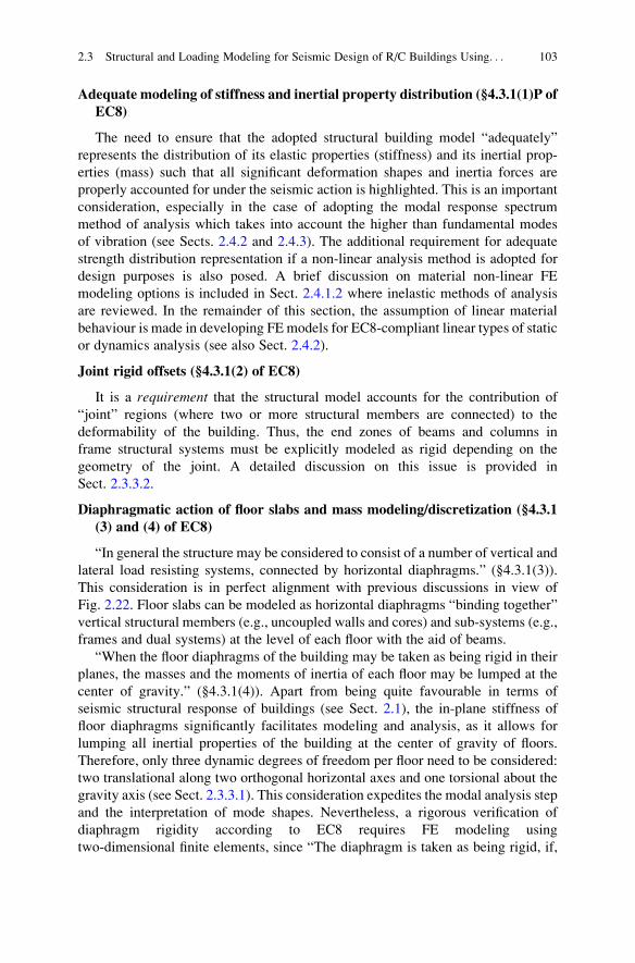
Adequate modeling of stiffness and inertial property distribution (§4.3.1(1)P of
EC8)
The need to ensure that the adopted structural building model “adequately”
represents the distribution of its elastic properties (stiffness) and its inertial prop-
erties (mass) such that all significant deformation shapes and inertia forces are
properly accounted for under the seismic action is highlighted. This is an important
consideration, especially in the case of adopting the modal response spectrum
method of analysis which takes into account the higher than fundamental modes
of vibration (see Sects. 2.4.2 and 2.4.3). The additional requirement for adequate
strength distribution representation if a non-linear analysis method is adopted for
design purposes is also posed. A brief discussion on material non-linear FE
modeling options is included in Sect. 2.4.1.2 where inelastic methods of analysis
are reviewed. In the remainder of this section, the assumption of linear material
behaviour is made in developing FEmodels for EC8-compliant linear types of static
or dynamics analysis (see also Sect. 2.4.2).
Joint rigid offsets (§4.3.1(2) of EC8)
It is a requirement that the structural model accounts for the contribution of
“joint” regions (where two or more structural members are connected) to the
deformability of the building. Thus, the end zones of beams and columns in
frame structural systems must be explicitly modeled as rigid depending on the
geometry of the joint. A detailed discussion on this issue is provided in
Sect. 2.3.3.2.
Diaphragmatic action of floor slabs and mass modeling/discretization (§4.3.1
(3) and (4) of EC8)
“In general the structure may be considered to consist of a number of vertical and
lateral load resisting systems, connected by horizontal diaphragms.” (§4.3.1(3)).
This consideration is in perfect alignment with previous discussions in view of
Fig. 2.22. Floor slabs can be modeled as horizontal diaphragms “binding together”
vertical structural members (e.g., uncoupled walls and cores) and sub-systems (e.g.,
frames and dual systems) at the level of each floor with the aid of beams.
“When the floor diaphragms of the building may be taken as being rigid in their
planes, the masses and the moments of inertia of each floor may be lumped at the
center of gravity.” (§4.3.1(4)). Apart from being quite favourable in terms of
seismic structural response of buildings (see Sect. 2.1), the in-plane stiffness of
floor diaphragms significantly facilitates modeling and analysis, as it allows for
lumping all inertial properties of the building at the center of gravity of floors.
Therefore, only three dynamic degrees of freedom per floor need to be considered:
two translational along two orthogonal horizontal axes and one torsional about the
gravity axis (see Sect. 2.3.3.1). This consideration expedites the modal analysis step
and the interpretation of mode shapes. Nevertheless, a rigorous verification of
diaphragm rigidity according to EC8 requires FE modeling using
two-dimensional finite elements, since “The diaphragm is taken as being rigid, if,
2.3 Structural and Loading Modeling for Seismic Design of R/C Buildings Using. . . 103
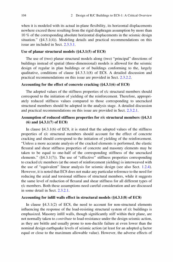
when it is modeled with its actual in-plane flexibility, its horizontal displacements
nowhere exceed those resulting from the rigid diaphragm assumption by more than
10 % of the corresponding absolute horizontal displacements in the seismic design
situation.” (§4.3.1(4)). Modeling details and practical recommendations on this
issue are included in Sect. 2.3.3.1.
Use of planar structural models (§4.3.1(5) of EC8)
The use of (two) planar structural models along (two) “principal” directions of
buildings instead of spatial (three-dimensional) models is allowed for the seismic
design of regular in plan buildings or of buildings conforming to the, largely
qualitative, conditions of clause §4.3.3.1(8) of EC8. A detailed discussion and
practical recommendations on this issue are provided in Sect. 2.3.2.2.
Accounting for the effect of concrete cracking (§4.3.1(6) of EC8)
The adopted values of the stiffness properties of r/c structural members should
correspond to the initiation of yielding of the reinforcement. Therefore, appropri-
ately reduced stiffness values compared to those corresponding to uncracked
structural members should be adopted in the analysis stage. A detailed discussion
and practical recommendations on this issue are provided in Sect. 2.3.2.1.
Assumption of reduced stiffness properties for r/c structural members (§4.3.1
(6) and §4.3.1(7) of EC8)
In clause §4.3.1(6) of EC8, it is stated that the adopted values of the stiffness
properties of r/c structural members should account for the effect of concrete
cracking and should correspond to the initiation of yielding of the reinforcement.
“Unless a more accurate analysis of the cracked elements is performed, the elastic
flexural and shear stiffness properties of concrete and masonry elements may be
taken to be equal to one-half of the corresponding stiffness of the uncracked
elements.” (§4.3.1(7)). The use of “effective” stiffness properties corresponding
to cracked r/c members (at the onset of reinforcement yielding) is interweaved with
the use of “equivalent” linear analysis for seismic design (see also Sect. 1.2.4).
However, it is noted that EC8 does not make any particular reference to the need for
reducing the axial and torsional stiffness of structural members, while it suggests
the same level of reduction of flexural and shear stiffness for all different types of
r/c members. Both these assumptions need careful consideration and are discussed
in some detail in Sect. 2.3.2.1.
Accounting for infill walls effect in structural models (§4.3.1(8) of EC8)
In clause §4.3.1(2) of EC8, the need to account for non-structural elements
influencing the response of the load-resisting structural system of r/c buildings is
emphasized. Masonry infill walls, though significantly stiff within their plane, are
not normally taken to contribute to load-resistance under the design seismic action,
as they are brittle and usually prone to non-ductile failure at even lower than the
nominal design earthquake levels of seismic action (at least for an adopted q factor
equal or close to the maximum allowable value). However, the adverse effects of
104 2 Design of R/C Buildings to EC8-1: A Critical Overview
non-uniform distribution of infill walls in plan and elevation need to be taken into
account in certain cases, as specified in clauses §4.3.1(8) and §4.3.6 of EC8. Further
details on this matter are provided in Sect. 3.3.
Foundation and supporting ground compliance (§4.3.1(9) of EC8)
“The deformability of the foundation shall be taken into account in the model,
whenever it may have an adverse overall influence on the structural response.”;
“Foundation deformability (including the soil-structure interaction) may always be
taken into account, including the cases in which it has beneficial effects.” (§4.3.1
(9)). The issue of whether and in which cases the effects of soil compliance and,
even more, the soil-structure interaction phenomenon have positive effects on the
seismic response of structures is open to research and is certainly not readily
predictable in advance. Therefore, it is generally recommended to include the
foundation and soil compliance in the overall structural model with due consider-
ation of the distinct features of static and dynamic soil-structure interaction. More
details on practical ways to accomplish this are provided in Sect. 2.3.3.5.
Inertial/Mass properties for seismic design (§4.3.1(10) of EC8)
“The masses shall be calculated from the gravity loads appearing in the combi-
nation of actions indicated in 3.2.4. The combination coefficients ψΕi are given in
4.2.4(2).” (§4.3.1(10)). This issue has already been discussed in Sect. 2.3.1.4 and is
only included here for the sake of completeness of the EC8 modelling requirements.
Guidance and recommendation on typical discretization FE schemes and model-
ing techniques for ordinary r/c buildings in accordance with the general EC8
modeling requirements are provided in Sect. 2.3.3. In the remainder of this section,
special attention is focused on two practical issues arising in the modeling stage of
the seismic design, as these can have a significant impact on the (linear) analysis
results and, therefore, on the final design. The first issue relates to the stiffness
reduction in r/c structural members due to concrete cracking. The second issue
relates to whether two-dimensional (planar) FE models can be adopted instead of
three-dimensional (spatial) models in the context of equivalent linear analysis. In
the following two paragraphs, certain comments and practical recommendations are
given in relation to the above two issues.
2.3.2.1 Stiffness Reduction of R/C Members for Linear Analysis (§4.3.1
(6) and (7) of EC8)
As already discussed in Sects. 1.1.5.4 and 1.2.4 and noted in clause §4.3.1(6) of
EC8, it is reasonable to assume that r/c structural members are cracked in
performing “equivalent” linear types of analysis using an inelastic spectrum to
define the seismic input action. Therefore, “effective” or “secant” stiffness values
should be considered which are typically found (e.g., by lab testing) to be signif-
icantly lower than the theoretical stiffness properties calculated from the uncracked
gross section properties of r/c members. That is,
2.3 Structural and Loading Modeling for Seismic Design of R/C Buildings Using. . . 105
– the flexural rigidity (EI),
– the shear rigidity (GAs),
– the axial rigidity (EA), and
– the torsional rigidity (GJ),
where
E is the modulus of elasticity,
G is the shear modulus,
A is the member cross-sectional area,
As is the member shear area,
I is the moment of inertia (second moment of area), and
J (or IT) is the torsional moment of inertia (polar moment of area).
It is further noted that, in the context of (linear) seismic analysis and design, the
overall stiffness of the r/c load-resisting structural system (and of its adopted
computational model) significantly influences its dynamical properties and ulti-
mately the design seismic effects. In particular, structural stiffness has a profound
effect on the value of the fundamental and the higher natural periods of the structure
which, in turn, influence the seismic loads obtained from the design spectrum of
Eq. (2.9), for which the structure needs to be designed. Further, the stiffness of the
load resisting structural system depends heavily on the stiffness properties of its
individual constituent r/c structural members. Therefore, care should be exercised
in the adopted values of effective/reduced r/c member stiffness properties account-
ing for concrete cracking. These values should not be unrealistically low, since this
will significantly increase the natural period of the structure and, thus, may under-
estimate the design seismic loads (see Fig. 2.21), leading to non-conservative
designs. Conversely, if relatively large values for secant stiffness properties are
adopted, excessively high design seismic loads may be reached, leading to cost-
ineffective designs.
According to EC8 (clause §4.3.1(7), the flexural rigidity (EI) and the shear
rigidity (GAs) should be reduced by 50 % in cracked members compared to the
uncracked values (unless a rigorous analysis is undertaken), assuming that such
reduced stiffnesses correspond to the initiation of yielding of the reinforcement
(clause §4.3.1(6)). The above default reduction to stiffness properties is considered
to be relatively small compared to what is observed in relevant experimental tests
(Fardis 2009). As such, it yields conservative (safe-sided) designs in the context of
force-based seismic design, though it may underestimate deformations. The latter
issue is not considered to be important, as EC8-prescribed deformation-based
verification checks (see Sect. 3.2) are usually not critical for the majority of
ordinary r/c building structures.
Furthermore, the assumption that the same level of flexural and shear stiffness
reduction, i.e., 50 %, applies to all different types of r/c members, combined with
the additional assumption that axial and torsional member deformations have
negligible influence on bending and shear stiffness, significantly expedites the
design process from a practical viewpoint, as the same structural (FE) model used
106 2 Design of R/C Buildings to EC8-1: A Critical Overview
for “equivalent” linear seismic analysis (assuming cracked r/c members) may also
be used for (linear) analysis under gravity loads (assuming uncracked r/c members),
i.e., for the ultimate limit state basic design combination for permanent and variable
actions (no accidental/seismic). This is because stress resultants obtained from
linear analysis for static externally applied loads (i.e., support settlements or
temperature effects are considered) depend only on the relative stiffness contribu-tion of each structural member (i.e., relative stiffness values assigned to each finite
element in the model), and not on the absolute stiffness values.
Nevertheless, despite being convenient for design purposes, it should be noted
that considering a uniform flexural and shear stiffness reduction for all types of
structural members is not realistic, since the extent of concrete cracking during
cyclic inelastic deformation is smaller for members carrying large axial forces (e.g.,
columns) compared to members under (almost pure) flexure (e.g., beams). In this
regard, EC8 (clause §4.3.1(7)) does allow for the adoption of more elaborate
stiffness properties if a more accurate analysis of the cracked elements is performed
without providing any further suggestions with regards to the nature of such an
analysis. To this end, it would be rational to relate the level of stiffness reduction to
the targeted seismic performance level, as this is expressed via the behaviour (force
reduction) factor q within the EC8-prescribed force based seismic design. In
particular:
– if a high seismic performance level is targeted (i.e., a relatively low value of the
behaviour factor q is adopted in design), the structure undergoes insignificant, if
any, inelastic deformation under the design seismic action and, thus, relatively
small stiffness reduction/degradation at structural members can be assumed due
to limited extent of concrete cracking; while
– if a low seismic performance level is targeted (i.e., a relatively large value of the
behaviour factor q close to the maximum allowable is adopted in design), the
structure undergoes significant inelastic deformation under the design seismic
action and, thus, significantly higher, compared to the previous case, stiffness
reduction/degradation at structural members needs to be assumed.
The above reasoning suggests that the adopted values for effective stiffness
properties corresponding to cracked members (i.e., flexural, shear, axial, and
torsional rigidity) should depend on the value of the behaviour factor q. However,
at present, no research work along these lines is found in the open technical
literature. In this respect, the cracked member (secant) stiffness at yield for several
types of r/c members reported in (Priestley et al. 2007) can be adopted as being a
function of axial loading.
As a final remark, it is noted that EC8 does not make any recommendation with
regards to effective/secant values for the axial and torsional rigidities of structural
members. It is recommended that the axial rigidity of cracked members remains the
same as that for the uncracked members. It is further emphasized that the torsional
stiffness of structural members has a non-negligible influence on seismic effects,
assuming that spatial (three-dimensional) FE models are used in the analysis, as
recommended in the next section. For example, the assumed value of torsional
2.3 Structural and Loading Modeling for Seismic Design of R/C Buildings Using. . . 107
stiffness in the modeling of r/c cores may influence design seismic effects in all
structural members of an r/c building (see Sect. 2.3.3.4). Given that torsional
stiffness is significantly reduced due to cracking, a reduced value in the uncracked
torsional stiffness (i.e., to the member torsional moment of inertia, IT) of the order
of 90 % is herein recommended (Fardis 2009).
2.3.2.2 On the Use of Planar Structural FE Models for Linear Analysis
(§4.3.1 of EC8)
Due to the practically unavoidable asymmetries in stiffness and inertial property
distribution within building structures, a certain level of “coupling” between trans-
lational and rotational response will always occur. The practical implications of this
coupling may be better understood by considering a three-dimensional linear FE
model of a regular building structure with vertical structural members and
sub-systems aligned parallel along two orthogonal horizontal axes X and
Y. Assuming that floor slabs behave as rigid diaphragms, each floor is assigned
two horizontal translational dynamic degrees of freedom along X and Y and one
rotational (torsional) degree of freedom about a vertical (gravitational) axis passing
through the floor center of gravity (§4.3.1(4) of EC8). An asymmetric stiffness
distribution and/or mass distribution in-plan would cause translational-rotational
mode coupling (see also Appendix B). Specifically, floor diaphragms would rotate
about a vertical axis under horizontal seismic action along the X or Y direction.
Consequently, these floor rotations will result in translations of structural members
along the Y or X directions, respectively. Clearly, such mode coupling effects
(or “torsional effects”), that is, horizontal translations along the perpendicular
direction to the direction of the seismic action, can only be accounted for in an
explicit manner by considering a spatial (three-dimensional) FE model. The sever-
ity of the torsional effects depends heavily on the level of observed in-plan
asymmetry (or eccentricity, as defined in Appendix B).
Still, in clause §4.3.1(5) of EC8, the consideration of two planar models (one
along each “principal direction” X and Y) is allowed to be used for “equivalent”
linear types of analysis for
– (a) regular in-plan buildings satisfying the conditions of §4.2.3.2; and for– (b) buildings of up to 10 m high having uniformly distributed infill walls and
rigid in plane floor slabs (clause §4.3.3.1(8) and (9) of EC8).
In case (b), the analysis results (seismic effects) are multiplied by a “corrective”
factor equal to 1.25. Further, in both cases, the torsional effects are implicitly taken
into account by multiplying the seismic design effects (stress resultants) in each
structural member determined by the planar models by a factor dependent on the
location of structural members in-plan and on the type of linear analysis
method used.
It should be recognized that allowing for the use of planar models together with
the above semi-empirical modifications aims to facilitate practical EC8 compliant
108 2 Design of R/C Buildings to EC8-1: A Critical Overview
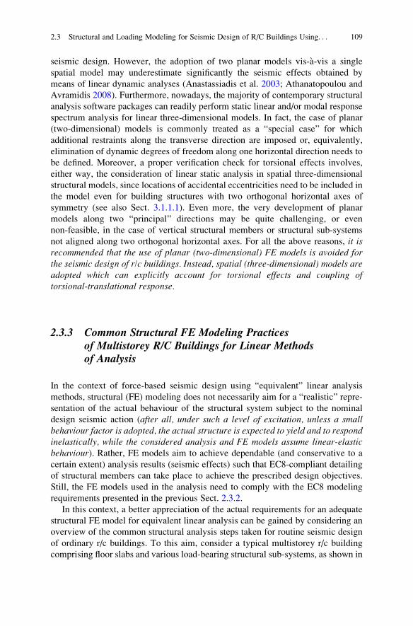
seismic design. However, the adoption of two planar models vis-�a-vis a single
spatial model may underestimate significantly the seismic effects obtained by
means of linear dynamic analyses (Anastassiadis et al. 2003; Athanatopoulou and
Avramidis 2008). Furthermore, nowadays, the majority of contemporary structural
analysis software packages can readily perform static linear and/or modal response
spectrum analysis for linear three-dimensional models. In fact, the case of planar
(two-dimensional) models is commonly treated as a “special case” for which
additional restraints along the transverse direction are imposed or, equivalently,
elimination of dynamic degrees of freedom along one horizontal direction needs to
be defined. Moreover, a proper verification check for torsional effects involves,
either way, the consideration of linear static analysis in spatial three-dimensional
structural models, since locations of accidental eccentricities need to be included in
the model even for building structures with two orthogonal horizontal axes of
symmetry (see also Sect. 3.1.1.1). Even more, the very development of planar
models along two “principal” directions may be quite challenging, or even
non-feasible, in the case of vertical structural members or structural sub-systems
not aligned along two orthogonal horizontal axes. For all the above reasons, it isrecommended that the use of planar (two-dimensional) FE models is avoided forthe seismic design of r/c buildings. Instead, spatial (three-dimensional) models areadopted which can explicitly account for torsional effects and coupling oftorsional-translational response.
2.3.3 Common Structural FE Modeling Practicesof Multistorey R/C Buildings for Linear Methodsof Analysis
In the context of force-based seismic design using “equivalent” linear analysis
methods, structural (FE) modeling does not necessarily aim for a “realistic” repre-
sentation of the actual behaviour of the structural system subject to the nominal
design seismic action (after all, under such a level of excitation, unless a smallbehaviour factor is adopted, the actual structure is expected to yield and to respondinelastically, while the considered analysis and FE models assume linear-elasticbehaviour). Rather, FE models aim to achieve dependable (and conservative to a
certain extent) analysis results (seismic effects) such that EC8-compliant detailing
of structural members can take place to achieve the prescribed design objectives.
Still, the FE models used in the analysis need to comply with the EC8 modeling
requirements presented in the previous Sect. 2.3.2.
In this context, a better appreciation of the actual requirements for an adequate
structural FE model for equivalent linear analysis can be gained by considering an
overview of the common structural analysis steps taken for routine seismic design
of ordinary r/c buildings. To this aim, consider a typical multistorey r/c building
comprising floor slabs and various load-bearing structural sub-systems, as shown in
2.3 Structural and Loading Modeling for Seismic Design of R/C Buildings Using. . . 109
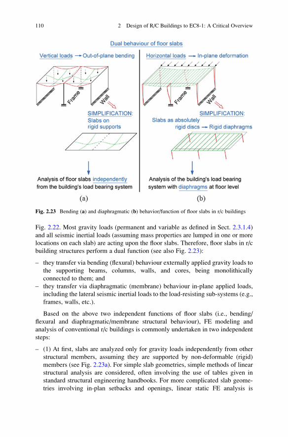
Fig. 2.22. Most gravity loads (permanent and variable as defined in Sect. 2.3.1.4)
and all seismic inertial loads (assuming mass properties are lumped in one or more
locations on each slab) are acting upon the floor slabs. Therefore, floor slabs in r/c
building structures perform a dual function (see also Fig. 2.23):
– they transfer via bending (flexural) behaviour externally applied gravity loads to
the supporting beams, columns, walls, and cores, being monolithically
connected to them; and
– they transfer via diaphragmatic (membrane) behaviour in-plane applied loads,
including the lateral seismic inertial loads to the load-resisting sub-systems (e.g.,
frames, walls, etc.).
Based on the above two independent functions of floor slabs (i.e., bending/
flexural and diaphragmatic/membrane structural behaviour), FE modeling and
analysis of conventional r/c buildings is commonly undertaken in two independent
steps:
– (1) At first, slabs are analyzed only for gravity loads independently from other
structural members, assuming they are supported by non-deformable (rigid)
members (see Fig. 2.23a). For simple slab geometries, simple methods of linear
structural analysis are considered, often involving the use of tables given in
standard structural engineering handbooks. For more complicated slab geome-
tries involving in-plan setbacks and openings, linear static FE analysis is
Fig. 2.23 Bending (a) and diaphragmatic (b) behavior/function of floor slabs in r/c buildings
110 2 Design of R/C Buildings to EC8-1: A Critical Overview
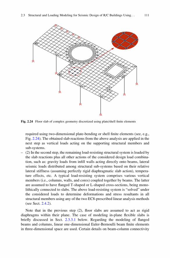
required using two-dimensional plate-bending or shell finite elements (see, e.g.,
Fig. 2.24). The obtained slab reactions from the above analysis are applied in the
next step as vertical loads acting on the supporting structural members and
sub-systems.
– (2) In the second step, the remaining load-resisting structural system is loaded by
the slab reactions plus all other actions of the considered design load combina-
tion, such as: gravity loads from infill walls acting directly onto beams, lateral
seismic loads distributed among structural sub-systems based on their relative
lateral stiffness (assuming perfectly rigid diaphragmatic slab action), tempera-
ture effects, etc. A typical load-resisting system comprises various vertical
members (i.e., columns, walls, and cores) coupled together by beams. The latter
are assumed to have flanged T-shaped or L-shaped cross-sections, being mono-
lithically connected to slabs. The above load-resisting system is “solved” under
the considered loads to determine deformations and stress resultants in all
structural members using any of the two EC8-prescribed linear analysis methods
(see Sect. 2.4.2).
Note that in the previous step (2), floor slabs are assumed to act as rigid
diaphragms within their plane. The case of modeling in-plane flexible slabs is
briefly discussed in Sect. 2.3.3.1 below. Regarding the modeling of flanged
beams and columns, linear one-dimensional Euler-Bernoulli beam finite elements
in three-dimensional space are used. Certain details on beam-column connectivity
Fig. 2.24 Floor slab of complex geometry discretized using plate/shell finite elements
2.3 Structural and Loading Modeling for Seismic Design of R/C Buildings Using. . . 111
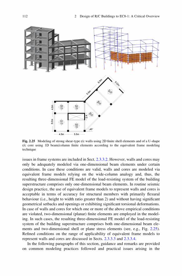
issues in frame systems are included in Sect. 2.3.3.2. However, walls and cores may
only be adequately modeled via one-dimensional beam elements under certain
conditions. In case these conditions are valid, walls and cores are modeled via
equivalent frame models relying on the wide-column analogy and, thus, the
resulting three-dimensional FE model of the load-resisting system of the building
superstructure comprises only one-dimensional beam elements. In routine seismic
design practice, the use of equivalent frame models to represent walls and cores is
acceptable in terms of accuracy for structural members with primarily flexural
behaviour (i.e., height to width ratio greater than 2) and without having significant
geometrical setbacks and openings or exhibiting significant torsional deformations.
In case of walls and cores for which one or more of the above empirical conditions
are violated, two-dimensional (planar) finite elements are employed in the model-
ing. In such cases, the resulting three-dimensional FE model of the load-resisting
system of the building superstructure comprises both one-dimensional beam ele-
ments and two-dimensional shell or plane stress elements (see, e.g., Fig. 2.25).
Refined conditions on the range of applicability of equivalent frame models to
represent walls and cores are discussed in Sects. 2.3.3.3 and 2.3.3.4.
In the following paragraphs of this section, guidance and remarks are provided
on common modeling practices followed and practical issues arising in the
Fig. 2.25 Modeling of strong shear-type r/c walls using 2D finite shell elements and of a U-shape
r/c core using 1D beam/column finite elements according to the equivalent frame modeling
technique
112 2 Design of R/C Buildings to EC8-1: A Critical Overview
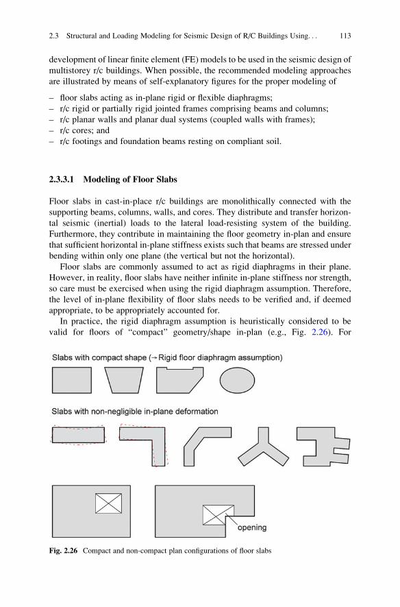
development of linear finite element (FE) models to be used in the seismic design of
multistorey r/c buildings. When possible, the recommended modeling approaches
are illustrated by means of self-explanatory figures for the proper modeling of
– floor slabs acting as in-plane rigid or flexible diaphragms;
– r/c rigid or partially rigid jointed frames comprising beams and columns;
– r/c planar walls and planar dual systems (coupled walls with frames);
– r/c cores; and
– r/c footings and foundation beams resting on compliant soil.
2.3.3.1 Modeling of Floor Slabs
Floor slabs in cast-in-place r/c buildings are monolithically connected with the
supporting beams, columns, walls, and cores. They distribute and transfer horizon-
tal seismic (inertial) loads to the lateral load-resisting system of the building.
Furthermore, they contribute in maintaining the floor geometry in-plan and ensure
that sufficient horizontal in-plane stiffness exists such that beams are stressed under
bending within only one plane (the vertical but not the horizontal).
Floor slabs are commonly assumed to act as rigid diaphragms in their plane.
However, in reality, floor slabs have neither infinite in-plane stiffness nor strength,
so care must be exercised when using the rigid diaphragm assumption. Therefore,
the level of in-plane flexibility of floor slabs needs to be verified and, if deemed
appropriate, to be appropriately accounted for.
In practice, the rigid diaphragm assumption is heuristically considered to be
valid for floors of “compact” geometry/shape in-plan (e.g., Fig. 2.26). For
Fig. 2.26 Compact and non-compact plan configurations of floor slabs
2.3 Structural and Loading Modeling for Seismic Design of R/C Buildings Using. . . 113
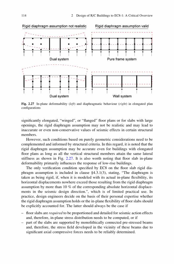
significantly elongated, “winged”, or “flanged” floor plans or for slabs with large
openings, the rigid diaphragm assumption may not be realistic and may lead to
inaccurate or even non-conservative values of seismic effects in certain structural
members.
However, such conditions based on purely geometric considerations need to be
complemented and informed by structural criteria. In this regard, it is noted that the
rigid diaphragm assumption may be accurate even for buildings with elongated
floor plans as long as all the vertical structural members attain the same lateral
stiffness as shown in Fig. 2.27. It is also worth noting that floor slab in-plane
deformability primarily influences the response of low-rise buildings.
The only verification condition specified by EC8 on the floor slab rigid dia-
phragm assumption is included in clause §4.3.1(3), stating, “The diaphragm is
taken as being rigid, if, when it is modeled with its actual in-plane flexibility, its
horizontal displacements nowhere exceed those resulting from the rigid diaphragm
assumption by more than 10 % of the corresponding absolute horizontal displace-
ments in the seismic design direction.”, which is of limited practical use. In
practice, design engineers decide on the basis of their personal expertise whether
the rigid diaphragm assumption holds or the in-plane flexibility of floor slabs should
be explicitly accounted for. The latter should always be the case if
– floor slabs are required to be proportioned and detailed for seismic action effects
and, therefore, in-plane stress distribution needs to be computed, or if
– part of the slabs are supported by monolithically connected pre-stressed beams
and, therefore, the stress field developed in the vicinity of these beams due to
significant axial compressive forces needs to be reliably determined.
Fig. 2.27 In-plane deformability (left) and diaphragmatic behaviour (right) in elongated plan
configurations
114 2 Design of R/C Buildings to EC8-1: A Critical Overview
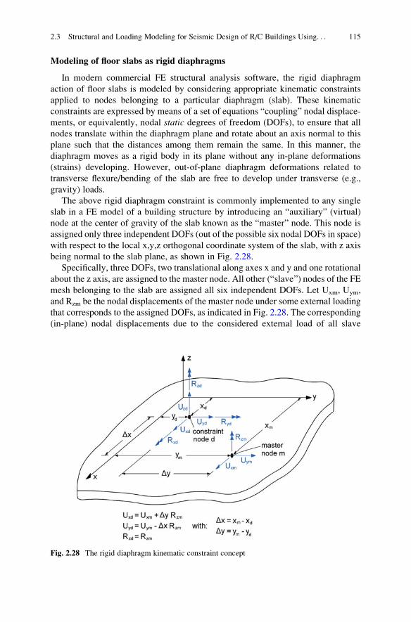
Modeling of floor slabs as rigid diaphragms
In modern commercial FE structural analysis software, the rigid diaphragm
action of floor slabs is modeled by considering appropriate kinematic constraints
applied to nodes belonging to a particular diaphragm (slab). These kinematic
constraints are expressed by means of a set of equations “coupling” nodal displace-
ments, or equivalently, nodal static degrees of freedom (DOFs), to ensure that all
nodes translate within the diaphragm plane and rotate about an axis normal to this
plane such that the distances among them remain the same. In this manner, the
diaphragm moves as a rigid body in its plane without any in-plane deformations
(strains) developing. However, out-of-plane diaphragm deformations related to
transverse flexure/bending of the slab are free to develop under transverse (e.g.,
gravity) loads.
The above rigid diaphragm constraint is commonly implemented to any single
slab in a FE model of a building structure by introducing an “auxiliary” (virtual)
node at the center of gravity of the slab known as the “master” node. This node is
assigned only three independent DOFs (out of the possible six nodal DOFs in space)
with respect to the local x,y,z orthogonal coordinate system of the slab, with z axis
being normal to the slab plane, as shown in Fig. 2.28.
Specifically, three DOFs, two translational along axes x and y and one rotational
about the z axis, are assigned to the master node. All other (“slave”) nodes of the FE
mesh belonging to the slab are assigned all six independent DOFs. Let Uxm, Uym,
and Rzm be the nodal displacements of the master node under some external loading
that corresponds to the assigned DOFs, as indicated in Fig. 2.28. The corresponding
(in-plane) nodal displacements due to the considered external load of all slave
Fig. 2.28 The rigid diaphragm kinematic constraint concept
2.3 Structural and Loading Modeling for Seismic Design of R/C Buildings Using. . . 115
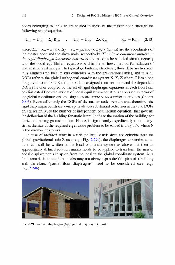
nodes belonging to the slab are related to those of the master node through the
following set of equations:
Uxd ¼ Uxm þ ΔyRzm , Uyd ¼ Uym � ΔxRzm , Rzd ¼ Rzm; ð2:13Þ
where Δx¼ xm� xd and Δy¼ ym� yd, and (xm, ym), (xd, yd) are the coordinates of
the master node and the slave node, respectively. The above equations implementthe rigid diaphragm kinematic constraint and need to be satisfied simultaneously
with the nodal equilibrium equations within the stiffness method formulation of
matrix structural analysis. In typical r/c building structures, floor slabs are horizon-
tally aligned (the local z axis coincides with the gravitational axis), and thus all
DOFs refer to the global orthogonal coordinate system X, Y, Z where Z lies along
the gravitational axis. Each floor slab is assigned a master node and the dependent
DOFs (the ones coupled by the set of rigid diaphragm equations at each floor) can
be eliminated from the system of nodal equilibrium equations expressed in terms of
the global coordinate system using standard static condensation techniques (Chopra2007). Eventually, only the DOFs of the master nodes remain and, therefore, the
rigid diaphragm constraint concept leads to a substantial reduction in the total DOFs
or, equivalently, to the number of independent equilibrium equations that governs
the deflection of the building for static lateral loads or the motion of the building for
horizontal strong ground motion. Hence, it significantly expedites dynamic analy-
sis, as the size of the required eigenvalue problem to be solved is only 3 N, where N
is the number of storeys.
In case of inclined slabs in which the local z axis does not coincide with the
global gravitational axis Z (see, e.g., Fig. 2.29a), the diaphragm constraint equa-
tions can still be written in the local coordinate system as above, but then an
appropriately defined rotation matrix needs to be applied to transform the master
nodal displacements in space from the local to the global coordinate system. As a
final remark, it is noted that slabs may not always span the full plan of a building
and, therefore, “partial floor diaphragms” need to be considered (see, e.g.,
Fig. 2.29b).
Fig. 2.29 Inclined diaphragm (left), partial diaphragm (right)
116 2 Design of R/C Buildings to EC8-1: A Critical Overview
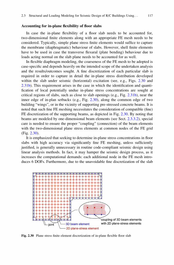
Accounting for in-plane flexibility of floor slabs
In case the in-plane flexibility of a floor slab needs to be accounted for,
two-dimensional finite elements along with an appropriate FE mesh needs to be
considered. Typically, simple plane stress finite elements would suffice to capture
the membrane (diaphragmatic) behaviour of slabs. However, shell finite elements
have to be used in case the transverse flexural (plate bending) behaviour due to
loads acting normal on the slab plane needs to be accounted for as well.
In flexible diaphragm modeling, the coarseness of the FE mesh to be adopted is
case-specific and depends heavily on the intended scope of the undertaken analysis
and the results/outcomes sought. A fine discretization of each particular slab is
required in order to capture in detail the in-plane stress distribution developed
within the slab under seismic (horizontal) excitation (see, e.g., Figs. 2.30 and
2.31b). This requirement arises in the case in which the identification and quanti-
fication of local potentially undue in-plane stress concentrations are sought at
critical regions of slabs, such as close to slab openings (e.g., Fig. 2.31b), near the
inner edge of in-plan setbacks (e.g., Fig. 2.30), along the common edge of two
building “wings”, or in the vicinity of supporting pre-stressed concrete beams. It is
noted that such fine FE meshing necessitates the consideration of compatible (fine)
FE discretization of the supporting beams, as depicted in Fig. 2.30. By noting that
beams are modeled by one-dimensional beam elements (see Sect. 2.3.3.2), special
care is needed to ensure the proper “coupling” (connection) of the beam elements
with the two-dimensional plane stress elements at common nodes of the FE grid
(Fig. 2.30).
It is emphasized that seeking to determine in-plane stress concentrations in floor
slabs with high accuracy via significantly fine FE meshing, unless sufficiently
justified, is generally unnecessary in routine code-compliant seismic design using
linear analysis methods. In fact, it may hamper the seismic design process, as it
increases the computational demands: each additional node in the FE mesh intro-
duces 6 DOFs. Furthermore, due to the unavoidable fine discretization of the slab
Fig. 2.30 Plane stress finite element discretization of in-plane flexible floor slab
2.3 Structural and Loading Modeling for Seismic Design of R/C Buildings Using. . . 117
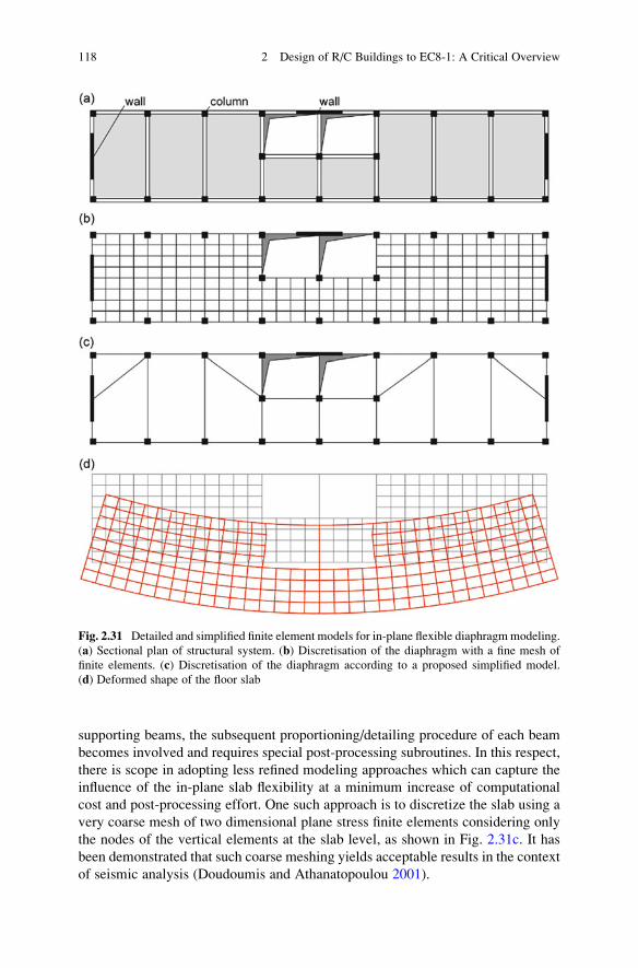
supporting beams, the subsequent proportioning/detailing procedure of each beam
becomes involved and requires special post-processing subroutines. In this respect,
there is scope in adopting less refined modeling approaches which can capture the
influence of the in-plane slab flexibility at a minimum increase of computational
cost and post-processing effort. One such approach is to discretize the slab using a
very coarse mesh of two dimensional plane stress finite elements considering only
the nodes of the vertical elements at the slab level, as shown in Fig. 2.31c. It has
been demonstrated that such coarse meshing yields acceptable results in the context
of seismic analysis (Doudoumis and Athanatopoulou 2001).
Fig. 2.31 Detailed and simplified finite element models for in-plane flexible diaphragmmodeling.
(a) Sectional plan of structural system. (b) Discretisation of the diaphragm with a fine mesh of
finite elements. (c) Discretisation of the diaphragm according to a proposed simplified model.
(d) Deformed shape of the floor slab
118 2 Design of R/C Buildings to EC8-1: A Critical Overview
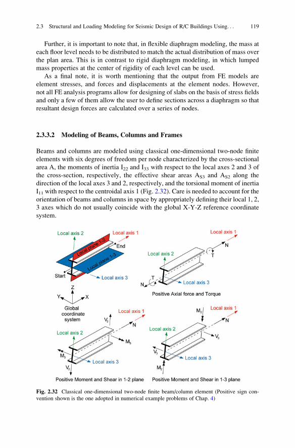
Further, it is important to note that, in flexible diaphragm modeling, the mass at
each floor level needs to be distributed to match the actual distribution of mass over
the plan area. This is in contrast to rigid diaphragm modeling, in which lumped
mass properties at the center of rigidity of each level can be used.
As a final note, it is worth mentioning that the output from FE models are
element stresses, and forces and displacements at the element nodes. However,
not all FE analysis programs allow for designing of slabs on the basis of stress fields
and only a few of them allow the user to define sections across a diaphragm so that
resultant design forces are calculated over a series of nodes.
2.3.3.2 Modeling of Beams, Columns and Frames
Beams and columns are modeled using classical one-dimensional two-node finite
elements with six degrees of freedom per node characterized by the cross-sectional
area A, the moments of inertia I22 and I33 with respect to the local axes 2 and 3 of
the cross-section, respectively, the effective shear areas AS3 and AS2 along the
direction of the local axes 3 and 2, respectively, and the torsional moment of inertia
I11 with respect to the centroidal axis 1 (Fig. 2.32). Care is needed to account for the
orientation of beams and columns in space by appropriately defining their local 1, 2,
3 axes which do not usually coincide with the global X-Y-Z reference coordinate
system.
Fig. 2.32 Classical one-dimensional two-node finite beam/column element (Positive sign con-
vention shown is the one adopted in numerical example problems of Chap. 4)
2.3 Structural and Loading Modeling for Seismic Design of R/C Buildings Using. . . 119
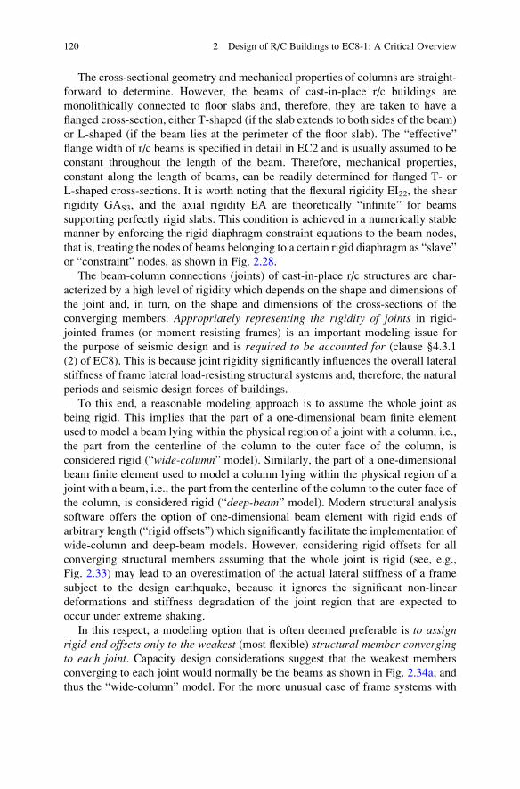
The cross-sectional geometry and mechanical properties of columns are straight-
forward to determine. However, the beams of cast-in-place r/c buildings are
monolithically connected to floor slabs and, therefore, they are taken to have a
flanged cross-section, either T-shaped (if the slab extends to both sides of the beam)
or L-shaped (if the beam lies at the perimeter of the floor slab). The “effective”
flange width of r/c beams is specified in detail in EC2 and is usually assumed to be
constant throughout the length of the beam. Therefore, mechanical properties,
constant along the length of beams, can be readily determined for flanged T- or
L-shaped cross-sections. It is worth noting that the flexural rigidity EI22, the shear
rigidity GAS3, and the axial rigidity EA are theoretically “infinite” for beams
supporting perfectly rigid slabs. This condition is achieved in a numerically stable
manner by enforcing the rigid diaphragm constraint equations to the beam nodes,
that is, treating the nodes of beams belonging to a certain rigid diaphragm as “slave”
or “constraint” nodes, as shown in Fig. 2.28.
The beam-column connections (joints) of cast-in-place r/c structures are char-
acterized by a high level of rigidity which depends on the shape and dimensions of
the joint and, in turn, on the shape and dimensions of the cross-sections of the
converging members. Appropriately representing the rigidity of joints in rigid-
jointed frames (or moment resisting frames) is an important modeling issue for
the purpose of seismic design and is required to be accounted for (clause §4.3.1
(2) of EC8). This is because joint rigidity significantly influences the overall lateral
stiffness of frame lateral load-resisting structural systems and, therefore, the natural
periods and seismic design forces of buildings.
To this end, a reasonable modeling approach is to assume the whole joint as
being rigid. This implies that the part of a one-dimensional beam finite element
used to model a beam lying within the physical region of a joint with a column, i.e.,
the part from the centerline of the column to the outer face of the column, is
considered rigid (“wide-column” model). Similarly, the part of a one-dimensional
beam finite element used to model a column lying within the physical region of a
joint with a beam, i.e., the part from the centerline of the column to the outer face of
the column, is considered rigid (“deep-beam” model). Modern structural analysis
software offers the option of one-dimensional beam element with rigid ends of
arbitrary length (“rigid offsets”) which significantly facilitate the implementation of
wide-column and deep-beam models. However, considering rigid offsets for all
converging structural members assuming that the whole joint is rigid (see, e.g.,
Fig. 2.33) may lead to an overestimation of the actual lateral stiffness of a frame
subject to the design earthquake, because it ignores the significant non-linear
deformations and stiffness degradation of the joint region that are expected to
occur under extreme shaking.
In this respect, a modeling option that is often deemed preferable is to assignrigid end offsets only to the weakest (most flexible) structural member convergingto each joint. Capacity design considerations suggest that the weakest members
converging to each joint would normally be the beams as shown in Fig. 2.34a, and
thus the “wide-column” model. For the more unusual case of frame systems with
120 2 Design of R/C Buildings to EC8-1: A Critical Overview
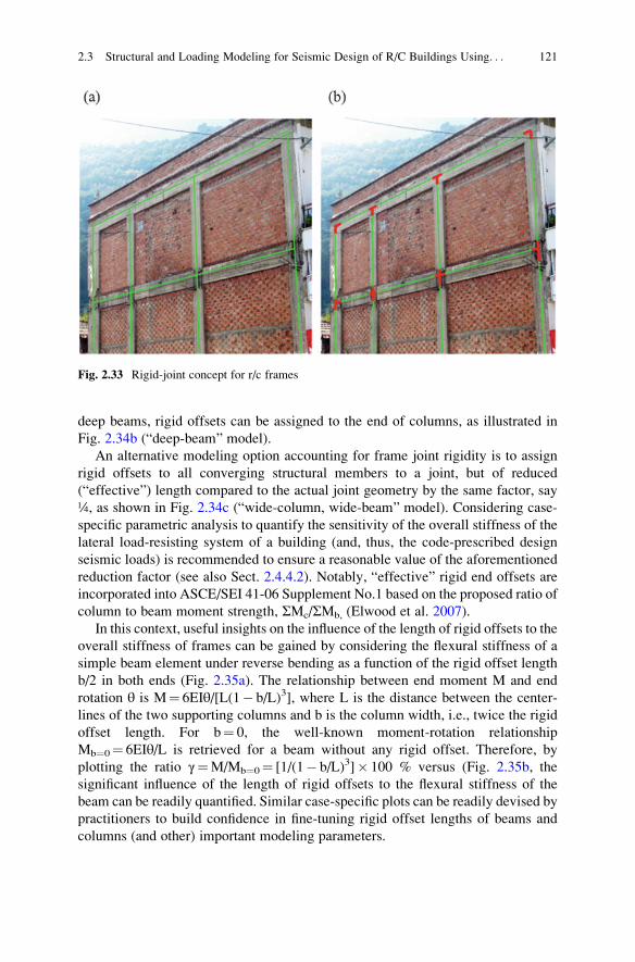
deep beams, rigid offsets can be assigned to the end of columns, as illustrated in
Fig. 2.34b (“deep-beam” model).
An alternative modeling option accounting for frame joint rigidity is to assign
rigid offsets to all converging structural members to a joint, but of reduced
(“effective”) length compared to the actual joint geometry by the same factor, say
¼, as shown in Fig. 2.34c (“wide-column, wide-beam” model). Considering case-
specific parametric analysis to quantify the sensitivity of the overall stiffness of the
lateral load-resisting system of a building (and, thus, the code-prescribed design
seismic loads) is recommended to ensure a reasonable value of the aforementioned
reduction factor (see also Sect. 2.4.4.2). Notably, “effective” rigid end offsets are
incorporated into ASCE/SEI 41-06 Supplement No.1 based on the proposed ratio of
column to beam moment strength, ΣMc/ΣMb, (Elwood et al. 2007).
In this context, useful insights on the influence of the length of rigid offsets to the
overall stiffness of frames can be gained by considering the flexural stiffness of a
simple beam element under reverse bending as a function of the rigid offset length
b/2 in both ends (Fig. 2.35a). The relationship between end moment M and end
rotation θ is M¼ 6EIθ/[L(1� b/L)3], where L is the distance between the center-
lines of the two supporting columns and b is the column width, i.e., twice the rigid
offset length. For b¼ 0, the well-known moment-rotation relationship
Mb¼0¼ 6EIθ/L is retrieved for a beam without any rigid offset. Therefore, by
plotting the ratio γ¼M/Mb¼0¼ [1/(1� b/L)3]� 100 % versus (Fig. 2.35b, the
significant influence of the length of rigid offsets to the flexural stiffness of the
beam can be readily quantified. Similar case-specific plots can be readily devised by
practitioners to build confidence in fine-tuning rigid offset lengths of beams and
columns (and other) important modeling parameters.
Fig. 2.33 Rigid-joint concept for r/c frames
2.3 Structural and Loading Modeling for Seismic Design of R/C Buildings Using. . . 121
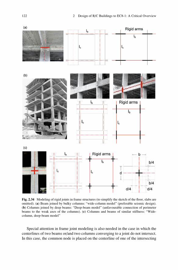
Special attention in frame joint modeling is also needed in the case in which the
centerlines of two beams or/and two columns converging to a joint do not intersect.
In this case, the common node is placed on the centerline of one of the intersecting
Fig. 2.34 Modeling of rigid joints in frame structures (to simplify the sketch of the floor, slabs are
omitted). (a) Beam joined by bulky columns: “wide-column model” (preferable seismic design).
(b) Columns joined by deep beams: “Deep-beam model” (unfavourable connection of perimeter
beams to the weak axes of the columns). (c) Columns and beams of similar stiffness: “Wide-
column, deep-beam model”
122 2 Design of R/C Buildings to EC8-1: A Critical Overview
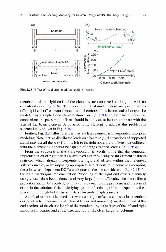
members and the rigid ends of the elements are connected to this joint with an
eccentricity (see Fig. 2.36). To this end, note that most modern analysis programs
offer rigid-end offset beam elements and, therefore, allow beams and columns to be
modeled by a single finite element shown in Fig. 2.36b. In the case of eccentric
connections in space, rigid offsets should be allowed to be non-collinear with the
axis of the beam element. A possible finite element to address this problem is
schematically shown in Fig. 2.36c.
Further, Fig. 2.37 illustrates the way such an element is incorporated into joint
modeling. Note that, as distributed loads on a beam (e.g., the reactions of supported
slabs) may act all the way from its left to its right node, rigid offsets non-collinear
with the element axis should be capable of being assigned loads (Fig. 2.36 c).
From the structural analysis viewpoint, it is worth noting that the computer
implementation of rigid offsets is achieved either by using beam element stiffness
matrices which already incorporate the rigid-end offsets within their element
stiffness matrix, or by imposing appropriate sets of constraint equations (coupling
the otherwise independent DOFs) analogous to the one considered in Eq. (2.13) for
the rigid diaphragm implementation. Modeling of the rigid end offsets manually
using virtual short beam elements of very large (“infinite”) values for the stiffness
properties should be avoided, as it may cause conditioning problems and numerical
errors in the solution of the underlying system of nodal equilibrium equations (i.e.,
inversion of the global stiffness matrix) for nodal displacements.
As a final remark, it is noted that, when end rigid offsets are present in a member,
design effects (cross-sectional internal forces and moments) are determined at the
end-sections of the elastic length of the member, i.e., at the faces of the left and right
supports for beams, and at the base and top of the clear height of columns.
Fig. 2.35 Effect of rigid arm length on bending moment
2.3 Structural and Loading Modeling for Seismic Design of R/C Buildings Using. . . 123
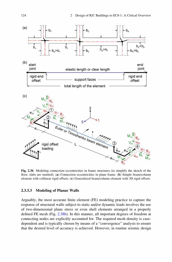
2.3.3.3 Modeling of Planar Walls
Arguably, the most accurate finite element (FE) modeling practice to capture the
response of structural walls subject to static and/or dynamic loads involves the use
of two-dimensional plane stress or even shell elements arranged in a properly
defined FE mesh (Fig. 2.38b). In this manner, all important degrees of freedom at
connecting nodes are explicitly accounted for. The required mesh density is case-
dependent and is typically chosen by means of a “convergence” analysis to ensure
that the desired level of accuracy is achieved. However, in routine seismic design
Fig. 2.36 Modeling connection eccentricities in frame structures (to simplify the sketch of the
floor, slabs are omitted). (a) Connection eccentricities in plane frame. (b) Simple beam/column
element with collinear rigid offsets. (c) Generalized beam/column element with 3D rigid offsets
124 2 Design of R/C Buildings to EC8-1: A Critical Overview
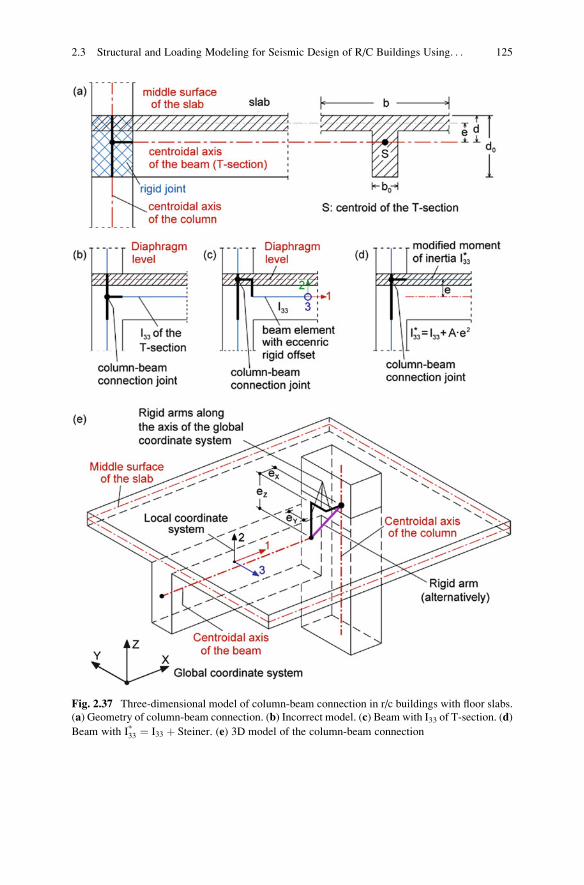
Fig. 2.37 Three-dimensional model of column-beam connection in r/c buildings with floor slabs.
(a) Geometry of column-beam connection. (b) Incorrect model. (c) Beam with I33 of T-section. (d)
Beam with I*33 ¼ I33 þ Steiner. (e) 3D model of the column-beam connection
2.3 Structural and Loading Modeling for Seismic Design of R/C Buildings Using. . . 125
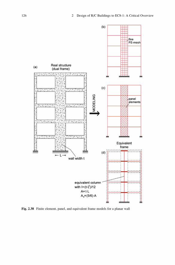
Fig. 2.38 Finite element, panel, and equivalent frame models for a planar wall
126 2 Design of R/C Buildings to EC8-1: A Critical Overview
practice of ordinary/conventional building structures, there is scope in avoiding
using such refined FE models since these models typically involve:
– Excessively tedious and time-consuming input data preparation process com-
pared to the alternative option discussed below,
– Post-processing difficulties concerning wall proportioning and detailing on the
basis of stress fields rather than on stress resultants, especially in the case of
multi-modal response spectrum analysis,
– Inconsistent (and unjustifiably high) level of accuracy given the large number of
over-simplifying/gross assumptions commonly made in code-prescribed seismic
analysis and modeling of ordinary r/c buildings, and
– Challenges arising in connecting the one-dimensional elements modeling the
beams at each floor level to the two-dimensional shell elements which may
require special local meshing to avoid the development of spurious local
stresses.
At a preliminary (conceptual) design stage, some of the above issues may be
bypassed using simple “panel element” models involving coarse FE mesh with only
one finite element per storey to model structural walls (Fig. 2.38c). However, such
models are too rough to be used for the main structural analysis stage. To this end,
simplified FE meshes comprising only one-dimensional (frame/beam) elements,
often called “equivalent frame models” (Fig. 2.38d), have been introduced by
(MacLeod 1977) to model structural walls as an alternative to more refined FE
models incorporating two-dimensional shell elements (MacLeod 1990; Stafford-
Smith and Girgis 1984). These simplified models are widely used, as they strike an
acceptable balance between accuracy and efficiency in capturing the behaviour of
slender walls exhibiting predominantly flexural/bending deformation (Fig. 2.39).
Conveniently, the majority of structural walls in earthquake-resistant buildings are
designed and expected to exhibit such behaviour under seismic loads.
The basic concept underlying the equivalent frame model consists in the replace-
ment of planar walls by one-dimensional frame/beam elements, often called
“equivalent columns”, positioned at the centerline (i.e. vertical centroidal axis) of
the actual wall and assigned section properties corresponding to the true geometry
of the wall (Fig. 2.38d). These equivalent columns are connected to the beams at the
floor levels by rigid arms (virtual perfectly rigid in flexure and in tension/compres-
sion one-dimensional beam elements) whose length reflects the actual width of the
wall. Similar modeling techniques as described in the previous section can be
applied to define the rigid arms, that is, by using either beam elements incorporating
end rigid offsets to their element stiffness matrix or by applying nodal constraints.
Clearly, the fundamental underlying principle of the above modeling technique
for walls is the Bernoulli assumption that plane sections remain plane and normal to
the deformed neutral axis. This is indicated for a simple coupled wall system in
Fig. 2.39 in which separate equivalent columns are used to model each wall
individually. Evidently, this assumption tends to become less realistic as the height
to width ratio h/b of the wall decreases. Therefore, as a general rule of thumb, the
equivalent frame model may be applied with acceptable accuracy for high-rise,
slender, bending/flexural type of walls with a ratio h/b of at least 4 (i.e. h/b> 4). It
2.3 Structural and Loading Modeling for Seismic Design of R/C Buildings Using. . . 127
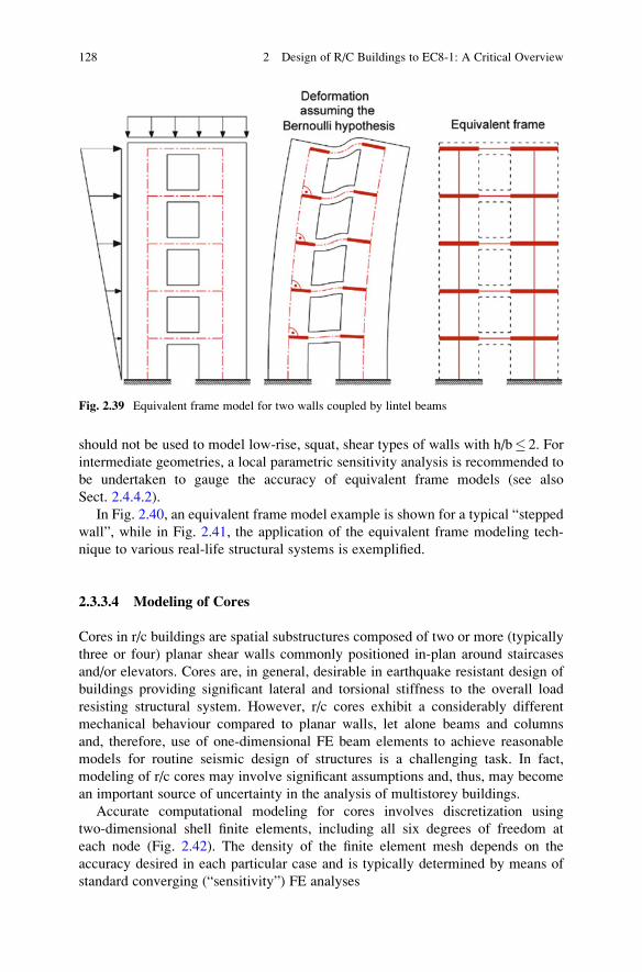
should not be used to model low-rise, squat, shear types of walls with h/b� 2. For
intermediate geometries, a local parametric sensitivity analysis is recommended to
be undertaken to gauge the accuracy of equivalent frame models (see also
Sect. 2.4.4.2).
In Fig. 2.40, an equivalent frame model example is shown for a typical “stepped
wall”, while in Fig. 2.41, the application of the equivalent frame modeling tech-
nique to various real-life structural systems is exemplified.
2.3.3.4 Modeling of Cores
Cores in r/c buildings are spatial substructures composed of two or more (typically
three or four) planar shear walls commonly positioned in-plan around staircases
and/or elevators. Cores are, in general, desirable in earthquake resistant design of
buildings providing significant lateral and torsional stiffness to the overall load
resisting structural system. However, r/c cores exhibit a considerably different
mechanical behaviour compared to planar walls, let alone beams and columns
and, therefore, use of one-dimensional FE beam elements to achieve reasonable
models for routine seismic design of structures is a challenging task. In fact,
modeling of r/c cores may involve significant assumptions and, thus, may become
an important source of uncertainty in the analysis of multistorey buildings.
Accurate computational modeling for cores involves discretization using
two-dimensional shell finite elements, including all six degrees of freedom at
each node (Fig. 2.42). The density of the finite element mesh depends on the
accuracy desired in each particular case and is typically determined by means of
standard converging (“sensitivity”) FE analyses
Fig. 2.39 Equivalent frame model for two walls coupled by lintel beams
128 2 Design of R/C Buildings to EC8-1: A Critical Overview
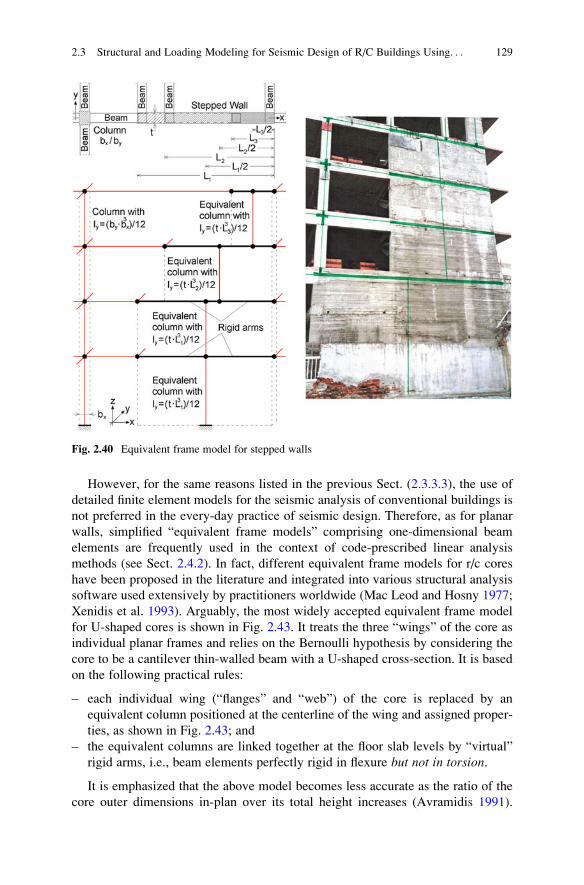
However, for the same reasons listed in the previous Sect. (2.3.3.3), the use of
detailed finite element models for the seismic analysis of conventional buildings is
not preferred in the every-day practice of seismic design. Therefore, as for planar
walls, simplified “equivalent frame models” comprising one-dimensional beam
elements are frequently used in the context of code-prescribed linear analysis
methods (see Sect. 2.4.2). In fact, different equivalent frame models for r/c cores
have been proposed in the literature and integrated into various structural analysis
software used extensively by practitioners worldwide (Mac Leod and Hosny 1977;
Xenidis et al. 1993). Arguably, the most widely accepted equivalent frame model
for U-shaped cores is shown in Fig. 2.43. It treats the three “wings” of the core as
individual planar frames and relies on the Bernoulli hypothesis by considering the
core to be a cantilever thin-walled beam with a U-shaped cross-section. It is based
on the following practical rules:
– each individual wing (“flanges” and “web”) of the core is replaced by an
equivalent column positioned at the centerline of the wing and assigned proper-
ties, as shown in Fig. 2.43; and
– the equivalent columns are linked together at the floor slab levels by “virtual”
rigid arms, i.e., beam elements perfectly rigid in flexure but not in torsion.
It is emphasized that the above model becomes less accurate as the ratio of the
core outer dimensions in-plan over its total height increases (Avramidis 1991).
Fig. 2.40 Equivalent frame model for stepped walls
2.3 Structural and Loading Modeling for Seismic Design of R/C Buildings Using. . . 129
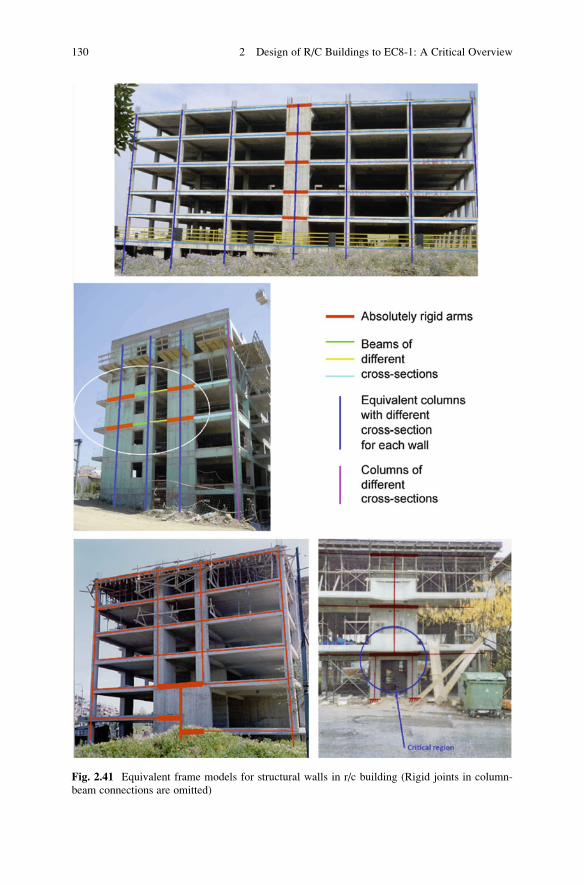
Fig. 2.41 Equivalent frame models for structural walls in r/c building (Rigid joints in column-
beam connections are omitted)
130 2 Design of R/C Buildings to EC8-1: A Critical Overview
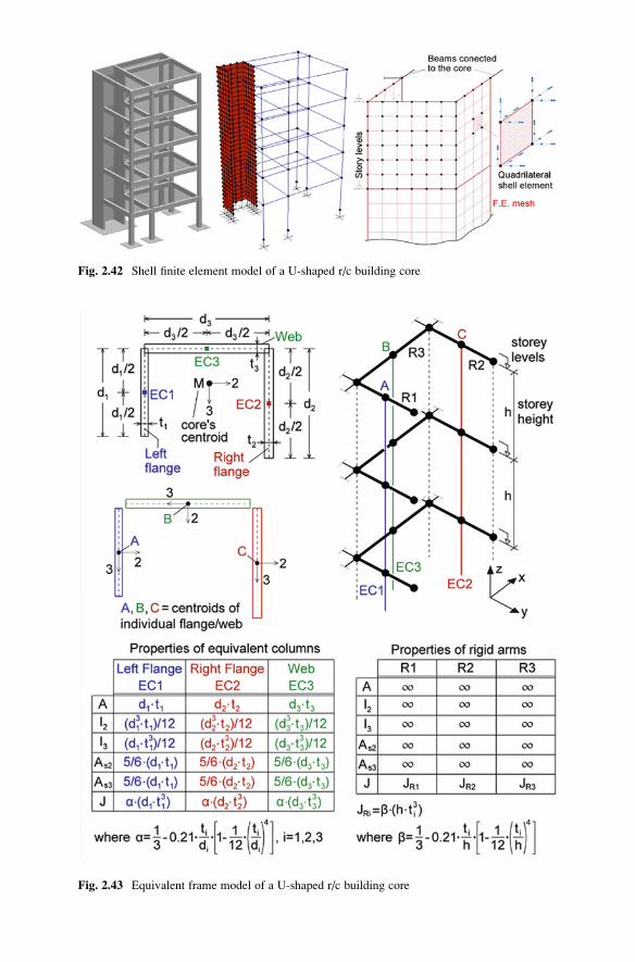
Fig. 2.43 Equivalent frame model of a U-shaped r/c building core
Fig. 2.42 Shell finite element model of a U-shaped r/c building core
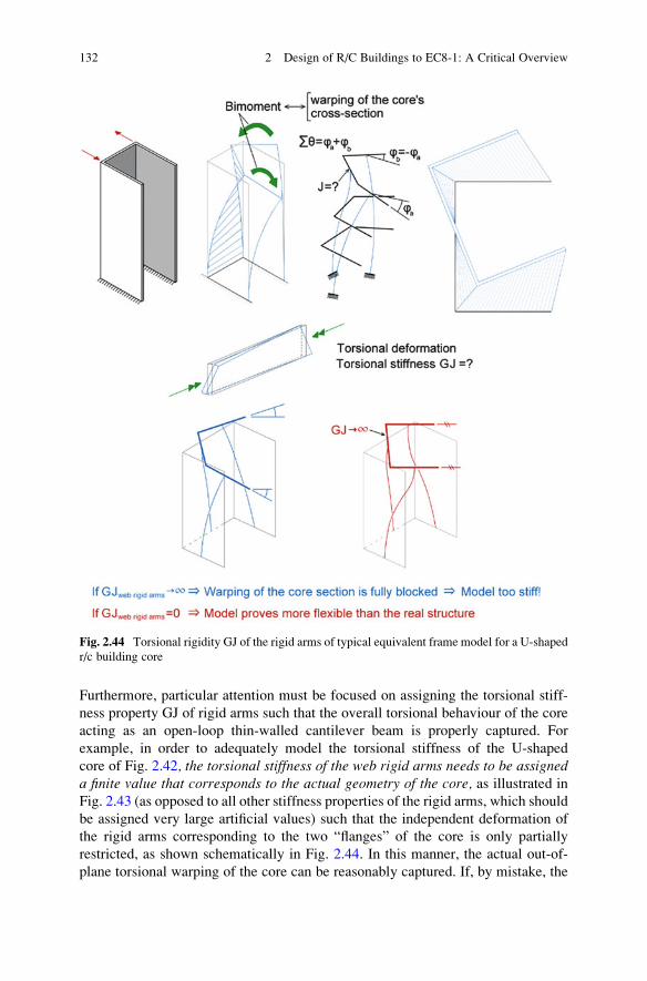
Furthermore, particular attention must be focused on assigning the torsional stiff-
ness property GJ of rigid arms such that the overall torsional behaviour of the core
acting as an open-loop thin-walled cantilever beam is properly captured. For
example, in order to adequately model the torsional stiffness of the U-shaped
core of Fig. 2.42, the torsional stiffness of the web rigid arms needs to be assigneda finite value that corresponds to the actual geometry of the core, as illustrated in
Fig. 2.43 (as opposed to all other stiffness properties of the rigid arms, which should
be assigned very large artificial values) such that the independent deformation of
the rigid arms corresponding to the two “flanges” of the core is only partially
restricted, as shown schematically in Fig. 2.44. In this manner, the actual out-of-
plane torsional warping of the core can be reasonably captured. If, by mistake, the
Fig. 2.44 Torsional rigidity GJ of the rigid arms of typical equivalent frame model for a U-shaped
r/c building core
132 2 Design of R/C Buildings to EC8-1: A Critical Overview
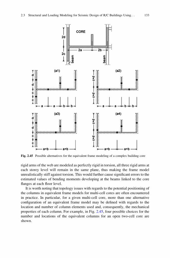
rigid arms of the web are modeled as perfectly rigid in torsion, all three rigid arms at
each storey level will remain in the same plane, thus making the frame model
unrealistically stiff against torsion. This would further cause significant errors to the
estimated values of bending moments developing at the beams linked to the core
flanges at each floor level.
It is worth noting that topology issues with regards to the potential positioning of
the columns in equivalent frame models for multi-cell cores are often encountered
in practice. In particular, for a given multi-cell core, more than one alternative
configuration of an equivalent frame model may be defined with regards to the
location and number of column elements used and, consequently, the mechanical
properties of each column. For example, in Fig. 2.45, four possible choices for the
number and locations of the equivalent columns for an open two-cell core are
shown.
Fig. 2.45 Possible alternatives for the equivalent frame modeling of a complex building core
2.3 Structural and Loading Modeling for Seismic Design of R/C Buildings Using. . . 133
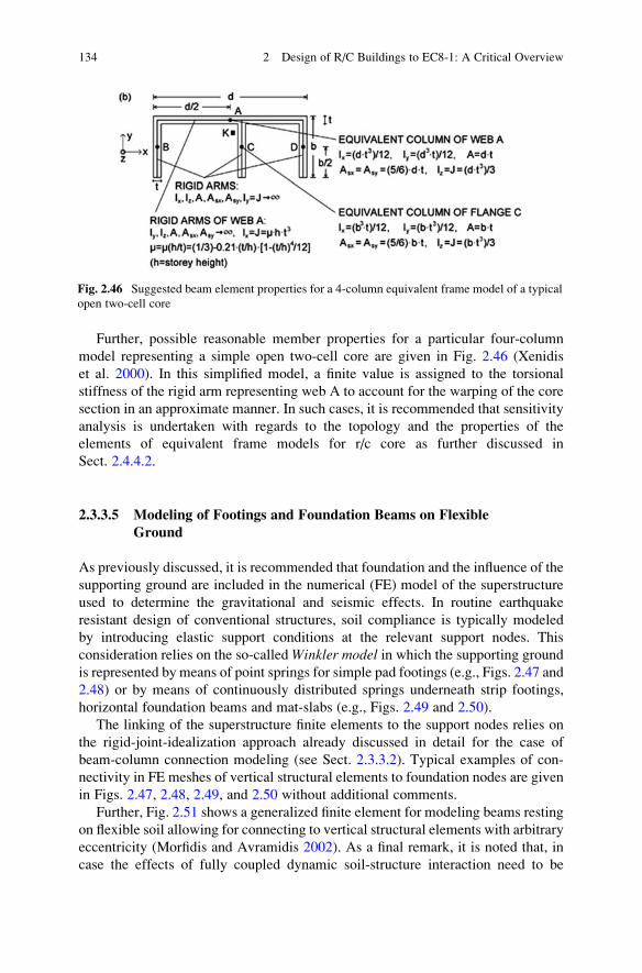
Further, possible reasonable member properties for a particular four-column
model representing a simple open two-cell core are given in Fig. 2.46 (Xenidis
et al. 2000). In this simplified model, a finite value is assigned to the torsional
stiffness of the rigid arm representing web A to account for the warping of the core
section in an approximate manner. In such cases, it is recommended that sensitivity
analysis is undertaken with regards to the topology and the properties of the
elements of equivalent frame models for r/c core as further discussed in
Sect. 2.4.4.2.
2.3.3.5 Modeling of Footings and Foundation Beams on Flexible
Ground
As previously discussed, it is recommended that foundation and the influence of the
supporting ground are included in the numerical (FE) model of the superstructure
used to determine the gravitational and seismic effects. In routine earthquake
resistant design of conventional structures, soil compliance is typically modeled
by introducing elastic support conditions at the relevant support nodes. This
consideration relies on the so-calledWinkler model in which the supporting groundis represented by means of point springs for simple pad footings (e.g., Figs. 2.47 and
2.48) or by means of continuously distributed springs underneath strip footings,
horizontal foundation beams and mat-slabs (e.g., Figs. 2.49 and 2.50).
The linking of the superstructure finite elements to the support nodes relies on
the rigid-joint-idealization approach already discussed in detail for the case of
beam-column connection modeling (see Sect. 2.3.3.2). Typical examples of con-
nectivity in FE meshes of vertical structural elements to foundation nodes are given
in Figs. 2.47, 2.48, 2.49, and 2.50 without additional comments.
Further, Fig. 2.51 shows a generalized finite element for modeling beams resting
on flexible soil allowing for connecting to vertical structural elements with arbitrary
eccentricity (Morfidis and Avramidis 2002). As a final remark, it is noted that, in
case the effects of fully coupled dynamic soil-structure interaction need to be
Fig. 2.46 Suggested beam element properties for a 4-column equivalent frame model of a typical
open two-cell core
134 2 Design of R/C Buildings to EC8-1: A Critical Overview
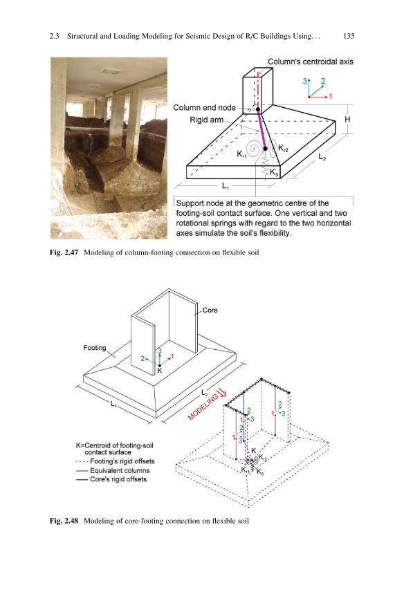
Fig. 2.48 Modeling of core-footing connection on flexible soil
Fig. 2.47 Modeling of column-footing connection on flexible soil
2.3 Structural and Loading Modeling for Seismic Design of R/C Buildings Using. . . 135
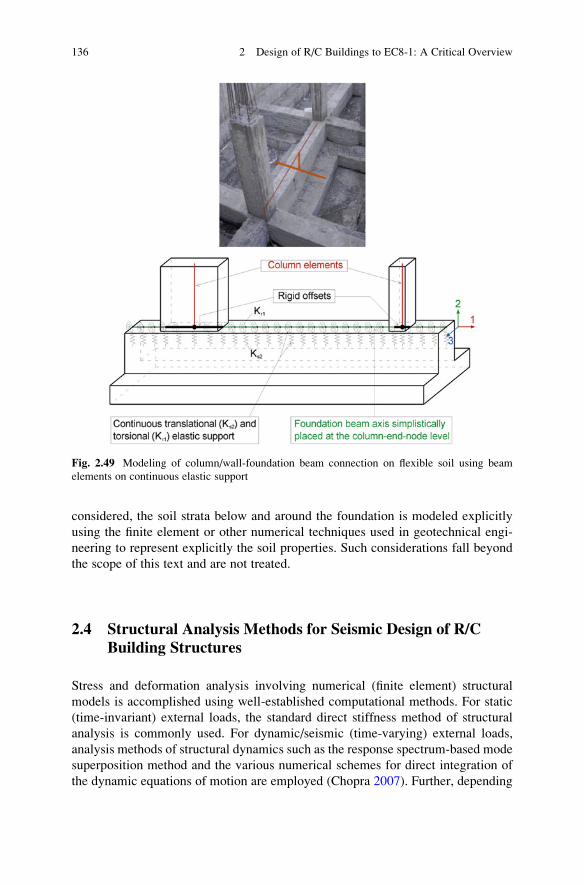
considered, the soil strata below and around the foundation is modeled explicitly
using the finite element or other numerical techniques used in geotechnical engi-
neering to represent explicitly the soil properties. Such considerations fall beyond
the scope of this text and are not treated.
2.4 Structural Analysis Methods for Seismic Design of R/CBuilding Structures
Stress and deformation analysis involving numerical (finite element) structural
models is accomplished using well-established computational methods. For static
(time-invariant) external loads, the standard direct stiffness method of structural
analysis is commonly used. For dynamic/seismic (time-varying) external loads,
analysis methods of structural dynamics such as the response spectrum-based mode
superposition method and the various numerical schemes for direct integration of
the dynamic equations of motion are employed (Chopra 2007). Further, depending
Fig. 2.49 Modeling of column/wall-foundation beam connection on flexible soil using beam
elements on continuous elastic support
136 2 Design of R/C Buildings to EC8-1: A Critical Overview
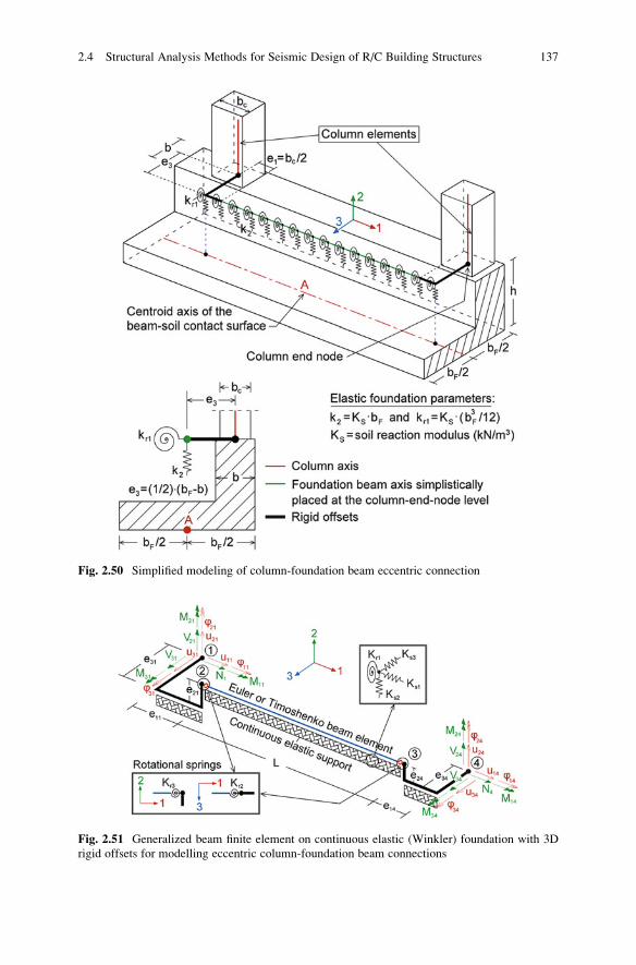
Fig. 2.50 Simplified modeling of column-foundation beam eccentric connection
Fig. 2.51 Generalized beam finite element on continuous elastic (Winkler) foundation with 3D
rigid offsets for modelling eccentric column-foundation beam connections
2.4 Structural Analysis Methods for Seismic Design of R/C Building Structures 137
on the intensity of the considered external loads, a given structure may deform
either elastically or elasto-plastically. In the latter case, the structure exhibits
non-linear inelastic (hysteretic) behaviour due to material non-linearity. Therefore,
the following four different types of analysis are readily identified depending on the
nature of the external loads (static or dynamic) and the material behaviour (elastic
or inelastic):
– Elastic static analysis (e.g., lateral force method)
– Elastic dynamic analysis (e.g., modal response spectrum method)
– Inelastic static analysis (e.g., non-linear pushover method)
– Inelastic dynamic analysis (e.g., non-linear response history method)
Moreover, the severity of the axial loads carried by structural members and the
level of structural deformations may require the consideration of second-order
theory (or at least inclusion of the P-Δ effects) to approximately account for the
potential geometrically non-linear behaviour.
For each of the above listed types of analysis, which may or may not account for
geometric non-linear phenomena, one or more analysis methods may be applicable.
In this regard, the question of “what is the most appropriate analysis method for r/cbuildings exposed to seismic loads?” becomes pertinent. Section 2.4.1 addresses
this question by taking into account the expected structural seismic performance
(i.e., severity of inelastic behaviour under a specific level of the seismic action)
beyond code-compliant seismic design. Section 2.4.2 lists the types of analysis
allowed by the EC8 for the design of new ordinary (conventional) structures. Next,
Sect. 2.4.3 includes remarks and recommendations for the practical implementation
of the most common analysis methods of EC8, including the inelastic static analysis
method (detailed in Appendix A). Finally, Sect. 2.4.4 discusses the need to verify
the distribution of overstrength across a structure in support of capacity design
approaches and to conduct parametric sensitivity analyses to quantify potentially
important sources of uncertainty in finite element modeling.
2.4.1 Selection of Structural Analysis Methods for SeismicDesign
It can be argued that, since code-compliant r/c building structures are usually
designed to yield under a design earthquake, an inelastic dynamic analysis method
such as the non-linear response history analysis (NRHA) should always be used forseismic design. However, this type of analysis poses a number of challenges to the
everyday practice of seismic design which may not be easily addressed by practi-
tioners. Specifically, NRHA involves direct integration of the equations of motion
in the time domain for a given input seismic ground motion record in terms of
acceleration (accelerogram). These equations of motion are derived upon appro-
priate modeling of the non-linear hysteretic (inelastic) material behaviour under
138 2 Design of R/C Buildings to EC8-1: A Critical Overview
cyclic loading (see further Sect. 2.4.1.2) and of any potential geometric
non-linearity due to gaps, discontinuities, friction, and second-order phenomena.
In this regard, the following main practical difficulties arise in applying NRHA for
the seismic design of new ordinary structures:
– Given the significant variability of the peak response of yielding structures
subject to recorded seismic accelerograms, there may be a lack of a sufficient
number of site-representative seismic records for design purposes. Note that this
issue can be addressed by using various record selection algorithms, e.g.,
(Katsanos and Sextos 2013) and/or by employing scaling/modification schemes
applied to recorded or artificial accelerograms, e.g., (Giaralis and Spanos 2009).
However, such considerations extend beyond the usual capacity of structural
design engineers as they require access to sufficiently large databases of
recorded accelerograms and to specialized software, along with the expertise
and experience to use such software properly.
– There exists a limited number of dependable hysteretic laws capable of ade-
quately capturing the inelastic behaviour of r/c structural members and of the
supporting soil in spatial (three-dimensional) finite element models available in
commercial software. Further, such hysteretic relationships involve a plethora of
parameters for each class of structural members (and soil types) which may not
be readily known/available to the design engineer (see also Sect. 2.4.1.2)
– There is limited knowledge and guidance for practitioners with regards to
allowable seismic demand limits for r/c structural members under different
dynamic load combinations. In more general terms, the verification, interpreta-
tion, and utilization of NRHA numerical results (i.e., time traces of structural
response quantities such as inelastic rotations at plastic hinges of critical zones
within various structural members) for design purposes requires considerable
experience and specialized expertise. The cost of such specialized consultancy
services in the routine seismic design of ordinary structures is not practically
justified.
– Dependable commercial software which may undertake NRHA within reason-
able time and monetary constraints applicable for the seismic design of ordinary
r/c building structures is scarce.
Furthermore, as has been discussed in Sects. 1.3 and 1.4, a building owner may
decide, in consultation with the design engineer, to adopt a higher seismic perfor-
mance level for the nominal design seismic action than the minimum life safety
(LS) performance level commonly targeted by the current (traditional) codes of
practice. This is achieved by ensuring different levels of stiffness, strength, and
ductility and, therefore, a given structure may be allowed to exhibit lower levels of
inelastic behaviour for the design seismic action up to “almost” elastic or even
purely elastic behaviour. Clearly, in the last two cases, undertaking NRHA is
unecessary, as a linear elastic dynamic analysis would be sufficient.
In this respect, for new structures, the selection of the most appropriate analysis
method, and, consequently, of a suitable computational (finite element) structural
model, depends primarily on the targeted/desired level of seismic performance to
2.4 Structural Analysis Methods for Seismic Design of R/C Building Structures 139
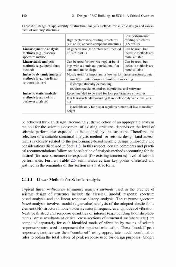
be achieved through design. Accordingly, the selection of an appropriate analysis
method for the seismic assessment of existing structures depends on the level of
seismic performance expected to be attained by the structure. Therefore, the
selection of a suitable structural analysis method for seismic design (and assess-
ment) is closely related to the performance-based seismic design philosophy and
considerations discussed in Sect. 1.3. In this respect, certain comments and practi-
cal recommendations follow on the selection of analysis methods accounting for the
desired (for new structures) or expected (for existing structures) level of seismic
performance. Further, Table 2.5 summarizes certain key points discussed and
justified in the remainder of this section in a matrix form.
2.4.1.1 Linear Methods for Seismic Analysis
Typical linear multi-mode (dynamic) analysis methods used in the practice of
seismic design of structures include the classical (modal) response spectrum
based analysis and the linear response history analysis. The response spectrumbased analysis involves modal (eigenvalue) analysis of the adopted elastic finite
element (FE) structural model to derive natural frequencies and modes of vibration.
Next, peak structural response quantities of interest (e.g., building floor displace-
ments, stress resultants at critical cross-sections of structural members, etc.) are
computed separately for each identified mode of vibration by means of seismic
response spectra used to represent the input seismic action. These “modal” peak
response quantities are then “combined” using appropriate modal combination
rules to obtain the total values of peak response used for design purposes (Chopra
Table 2.5 Range of applicability of structural analysis methods for seismic design and assess-
ment of ordinary structures
High performance existing structures
(OP or IO) or code-compliant structures
Low performance
existing structures
(LS or CP)
Linear dynamic analysismethods (e.g., responsespectrum method)
Of general use (the “reference” method
of EC8-part 1)
Can be used, but
inelastic methods are
more suitable
Linear static analysismethods (e.g., lateral forcemethod)
Can be used for low-rise regular build-
ings with a dominant translational fun-
damental mode shape
Can be used, but
inelastic methods are
more suitable
Inelastic dynamic analysismethods (e.g., non-linearresponse history)
Mostly used for important or low performance structures, but:
involves limitations/uncertainties in modeling
is computationally demanding
requires special expertise, experience, and software
Inelastic static analysismethods (e.g., inelasticpushover analysis)
Recommended to be used for low performance structures
It is less involved/demanding than inelastic dynamic analyses,
but:
is reliable only for planar regular structures of low to medium
height
140 2 Design of R/C Buildings to EC8-1: A Critical Overview
2007). The linear response history analysis considers seismic accelerograms to
represent the input seismic action in the same manner as the non-linear (inelastic)
response history analysis (NRHA) previously discussed. However, non-linear phe-
nomena are not accounted for in the development of the FE models and, therefore,
the numerical integration of the underlying equations of motion may involve modal
analysis based techniques.
Such linear dynamic methods of analysis should normally be used for structures
exhibiting relatively high seismic performance levels (e.g., “operational” or
“immediate occupancy” in Fig. 1.15) or structures whose structural members
exhibit a low demand capacity ratio (DCR). The latter is defined as the ratio of
seismic demand over the capacity of a particular (critical) cross-section. These
structures are expected to suffer very little, if any, structural damage under the
design seismic action and, thus, they respond in an “almost linear” fashion.
Further, linear single-mode (fundamental-mode) static analysis methods can be
used in the special case of high performance low-rise regular building structures.
These structures have a dominant translational fundamental mode of vibration and,
therefore, the influence of higher modes of vibration on their overall dynamic
response is insignificant. An example of a typical single-mode linear elastic static
analysis method is the “lateral force method” prescribed in the EC8 (§ 4.3.2.2 of
EC8) which is further discussed in Sects. 2.4.3 and 3.1.5.2 (see also flowchart 3.8).
The seismic action is represented by means of a seismic response spectrum which is
used to define the seismic design base shear force (see, e.g., Fig. 1.5) corresponding
to the first (fundamental) natural period of the structure. This base shear force is
distributed along the height of a building following an inverted triangular pattern in
the form of lateral static loads applied to floor masses lumped at pre-defined
locations on each storey level.
At this point, it is important to note that EC8 treats “equivalent” linear response
spectrum based dynamic or static (for regular buildings) analysis methods as the
“preferred” ones for the design of new structures, even though they may exhibit a
relatively low, “life safety”, seismic performance level (i.e., in case of adopting the
maximum, or close to the maximum, allowed value of the behaviour factor q). As
already discussed in Sect. 1.2.4, this is accomplished by adopting an “inelastic”
design (response) spectrum of reduced spectral ordinates compared to the elastic
response spectrum in defining the input seismic action. In this manner, the range of
applicability of linear elastic analysis methods is broadened to include the case of
moderate-to-low seismic performance levels in undertaking code-compliant seis-
mic design of ordinary building structures.
It is further noted that the use of linear methods of analysis for the case of
building structures exhibiting locally strong inelastic behaviour is also allowed in
the pertinent American pre-standards within the performance-based seismic design
framework [e.g., ASCE 41-06] (ASCE 2007). However, in these documents the
unreduced elastic response spectrum is considered in the determination of the
seismic input loads and, instead of a universal reduction behaviour factor q applied
to the loads, a local reduction factor m is applied to the stress resultants at the
critical cross-sections. The latter factor accounts for the local ductility capacity of
2.4 Structural Analysis Methods for Seismic Design of R/C Building Structures 141
cross-sections and its value is given in tabular form for each type of structural
member and assumed level of seismic performance. For example, for r/c columns
m¼ 1.25 ~ 2.00 for immediate occupancy performance level, m¼ 1.75 ~ 3.00 for
life safety performance level, and m¼ 1.75 ~ 4.00 for collapse prevention perfor-
mance level. Further, for the case of cross-sections of reduced ductility capacity
bearing significant compressive or shearing stresses, m¼ 1. Interestingly, the m
factor is applied to stress resultants due to both the seismic and the gravitational
load combination.
The above discussion highlights the rationale of using response spectrum based
(dynamic or static) linear methods of analysis within a performance-based seismic
design and assessment philosophy for yielding structures. Nevertheless, it is
emphasized that the use of such methods outside the prescriptive seismic codes of
practice and/or the relevant pre-standards is not recommended for the case of
structures exhibiting strongly inelastic behaviour. Instead, inelastic methods of
analysis should be preferred which account for the non-linear inelastic behaviour
of structures in an explicit manner.
2.4.1.2 Non-Linear Methods for Seismic Analysis
The dynamic non-linear response history analysis (NRHA) method is the most
refined and detailed type of inelastic analysis and can be theoretically applied to any
type of structure whether it exhibits inelastic behaviour or not under a given seismic
ground motion excitation. Focusing on r/c building structures, NRHA accounts for
the seismic/cyclic response of r/c structural members explicitly by considering
either distributed (fiber) or lumped (discrete) plasticity non-linear FE structural
models.
The use of lumped plasticity models is a long established approach involving
elastic one-dimensional “beam/column elements” with end member point plastic
hinges. These plastic hinges are represented by inelastic rotational springs
connected in series to the elastic beam/column elements. In this regard, a set of
assumptions needs to be made regarding the length of the plastic hinge and the
adoption of an appropriate hysteresis law in the form of moment-curvature or
moment-rotation relationships for the rotational springs of each r/c structural
member. These assumptions are often associated with non-negligible uncertainty.
Specifically, the length of the assumed plastic hinges is one controversial issue;
typically, this is to some extent compensated by either using semi-empirical
expressions found in the literature (Penelis and Kappos 1997) or by modeling the
critical zones for energy dissipation of structural members with multiple small-
length elements having adequately closely spaced rotational springs (Kappos and
Sextos 2001). Further, numerous hysteretic material laws are available for captur-
ing the post-yielding behaviour of r/c members under cyclic loading, including
stiffness degradation, strength deterioration, and the pinching effect (Katsanos
et al. 2014). However, such advanced material models are hardly ever used in the
design of ordinary structures, as they require a large number of input parameters
142 2 Design of R/C Buildings to EC8-1: A Critical Overview
which usually are not readily available. More importantly, the current state-of-the-
art suggests that lumped plasticity models can be used to perform reliable and
numerically stable NRHA only in planar (two-dimensional) structural models.
Lumped plasticity hysteretic laws for spatial (three-dimensional) FE models that
are sufficiently simple, general, and numerically robust for practical design pur-
poses are not available. Thus, in the case most needed in design (e.g., for asym-
metric in-plan building structures with significant torsional response exposed to two
horizontal components of the seismic ground motion), lumped plasticity models do
not offer a reliable analysis option.
An alternative to the lumped plasticity approach is the so-called distributed
(fiber) plasticity models which lend themselves to more reliable NRHA for spatial
FE models. In distributed plasticity models, the cross-section of each structural
member, including the reinforcing rebar, is discretized into a set of longitudinal
fibers. Each fiber is assigned an appropriate non-linear uniaxial stress-strain rela-
tionship. Next, integration operations lead to the desired stress-strain relationship of
the entire section (Fardis 2009). An advantage of this approach is that the hysteretic
behaviour of cross-sections is explicitly derived based on the inherent material
constitutive relationships, while the time-varying axial load in structural members
is also accounted for during run time. However, the required computational time for
NRHA using distributed plasticity spatial FE models for a sufficiently large number
of representative strong ground motions is practically prohibitive for the design of
ordinary r/c structures.
Overall, in view of the above brief presentation on available options for
non-linear material modeling, it can be concluded that the required modeling effort,
computational demand, and experience in defining the non-linear properties of the
structural FE models, in selecting and appropriately scaling the input ground
motions, and in the proper interpretation and validation of numerical results,
renders the use of NRHA for the seismic design of new structures impractical. To
this end, a plethora of inelastic static analysis methods have been proposed to
circumvent some of the above challenges and difficulties associated with the
application of NRHA, while aiming to capture/predict more realistically the
response of structures designed for relatively low seismic performance levels
(e.g., “life safety”) than the code-prescribed “equivalent” linear elastic methods
discussed in the previous section. It is noted that these methods are not based on any
rigorous theoretical background and rely on assumptions and methodologies that, in
many cases, contradict basic principles of structural mechanics (e.g., invoking the
principle of superposition for non-linear structures). Still, they are being exten-
sively used in practice, especially for evaluating the seismic vulnerability of
existing (code-deficient) structures.
Of these inelastic static analysis methods, the least involved, namely the non-adaptive single-mode inelastic pushover analysis or simply the standard pushoveranalysis (SPA), has been adopted for the design of new structures and the assess-
ment of existing structures by current codes of practice, including the EC8 (see also
Sects. 2.4.2 and 2.4.3.4). In brief, SPA is a modern variation of the classical plastic
‘collapse’ analysis adequately adapted to seismically excited structures aiming to
2.4 Structural Analysis Methods for Seismic Design of R/C Building Structures 143
predict the hierarchy of (localized) structural damages up to the onset of collapse
(Krawinkler and Seneviratna 1998). It considers monotonically increasing lateral
loads applied statically to the structure following a particular distribution along the
height of the building resembling the distribution of the fundamental modal forces
that the structure would be subjected to under horizontal dynamic support excita-
tion. As these loads increase, a series of plastic hinges develop gradually at critical
sections of the structure, leading to force redistribution and eventually to a failure
mechanism (see also Fig. 2.13). Therefore, through this analysis, it is possible to
obtain the non-linear relationship (pushover curve) between the sum of the lateral
applied force (base shear) and the deformation of the structure monitored at a
specific location. Based on this curve, various approaches exist for the definition
of a surrogate (“equivalent”) single-degree-of-freedom (SDOF) oscillator which
may be non-linear/inelastic, e.g., EC8-1 Annex B (CEN 2004), FEMA356 (FEMA
2000), or linear heavily damped, e.g. ATC-40 (Applied Technology Council 1996).
This SDOF-oscillator is used in conjunction with seismic response spectra for
seismic performance assessment (and/or design) of the considered structure, see
also FEMA440 (FEMA 2005).
Several variants of the SPA exist which account for the influence of the com-
puted “equivalent” SDOF oscillator properties (Manoukas et al. 2011) for the
influence of higher modes of vibration, such as the modal pushover analysis(Chopra and Goel 2002; Goel and Chopra 2005; Manoukas et al. 2012; Paraskeva
et al. 2006; Paraskeva and Kappos 2010), and/or for the fact that seismic load
distributions change as the structure yields, such as the adaptive pushover analysis(Antoniou and Pinho 2002; Elnashai 2001). Clearly, these and other existing
variants of the SPA come at an increase in computational cost and modeling effort,
while their availability in commercial structural analysis software is currently quite
limited. In terms of material non-linearity modeling, both lumped and distributed
plasticity models can be used in conjunction with inelastic static analyses. Com-
pared to the case of NRHA, the required (monotonic rather than cyclic) moment-
curvature relationships for the definition of plastic hinge properties at critical cross-
sections of r/c buildings can be derived in a much easier fashion. This is achieved by
means of readily available software performing conventional fiber model analysis
given a reasonable estimate of the member axial load. Alternatively, tables of
plastic hinge properties aiming to facilitate the practical implementation of inelastic
static analyses are available in the public domain, e.g., ASCE-41 (ASCE 2007), and
can be adopted for undertaking SPA or its variants. Still, the application of inelastic
static (pushover) analyses to spatial FE models with gradually increasing lateral
loads in two orthogonal directions is computationally sensitive, and it is not
recommended for practical seismic design and assessment purposes. Thus, static
inelastic analysis methods share the same practical limitation with the NRHA in
terms of applicability: they can be reliably applied only to planar FE models.
144 2 Design of R/C Buildings to EC8-1: A Critical Overview
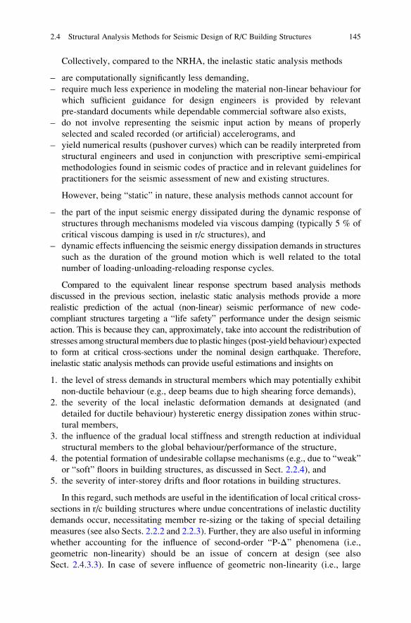
Collectively, compared to the NRHA, the inelastic static analysis methods
– are computationally significantly less demanding,
– require much less experience in modeling the material non-linear behaviour for
which sufficient guidance for design engineers is provided by relevant
pre-standard documents while dependable commercial software also exists,
– do not involve representing the seismic input action by means of properly
selected and scaled recorded (or artificial) accelerograms, and
– yield numerical results (pushover curves) which can be readily interpreted from
structural engineers and used in conjunction with prescriptive semi-empirical
methodologies found in seismic codes of practice and in relevant guidelines for
practitioners for the seismic assessment of new and existing structures.
However, being “static” in nature, these analysis methods cannot account for
– the part of the input seismic energy dissipated during the dynamic response of
structures through mechanisms modeled via viscous damping (typically 5 % of
critical viscous damping is used in r/c structures), and
– dynamic effects influencing the seismic energy dissipation demands in structures
such as the duration of the ground motion which is well related to the total
number of loading-unloading-reloading response cycles.
Compared to the equivalent linear response spectrum based analysis methods
discussed in the previous section, inelastic static analysis methods provide a more
realistic prediction of the actual (non-linear) seismic performance of new code-
compliant structures targeting a “life safety” performance under the design seismic
action. This is because they can, approximately, take into account the redistribution of
stresses among structuralmembers due to plastic hinges (post-yield behaviour) expected
to form at critical cross-sections under the nominal design earthquake. Therefore,
inelastic static analysis methods can provide useful estimations and insights on
1. the level of stress demands in structural members which may potentially exhibit
non-ductile behaviour (e.g., deep beams due to high shearing force demands),
2. the severity of the local inelastic deformation demands at designated (and
detailed for ductile behaviour) hysteretic energy dissipation zones within struc-
tural members,
3. the influence of the gradual local stiffness and strength reduction at individual
structural members to the global behaviour/performance of the structure,
4. the potential formation of undesirable collapse mechanisms (e.g., due to “weak”
or “soft” floors in building structures, as discussed in Sect. 2.2.4), and
5. the severity of inter-storey drifts and floor rotations in building structures.
In this regard, such methods are useful in the identification of local critical cross-
sections in r/c building structures where undue concentrations of inelastic ductility
demands occur, necessitating member re-sizing or the taking of special detailing
measures (see also Sects. 2.2.2 and 2.2.3). Further, they are also useful in informing
whether accounting for the influence of second-order “P-Δ” phenomena (i.e.,
geometric non-linearity) should be an issue of concern at design (see also
Sect. 2.4.3.3). In case of severe influence of geometric non-linearity (i.e., large
2.4 Structural Analysis Methods for Seismic Design of R/C Building Structures 145
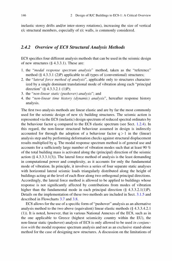
inelastic storey drifts and/or inter-storey rotations), increasing the size of vertical
r/c structural members, especially of r/c walls, is commonly considered.
2.4.2 Overview of EC8 Structural Analysis Methods
EC8 specifies four different analysis methods that can be used in the seismic design
of new structures (§ 4.3.3.1). These are:
1. the “modal response spectrum analysis” method, taken as the “reference”
method (§ 4.3.3.1 (2)P) applicable to all types of (conventional) structures;
2. the “lateral force method of analysis”, applicable only to structures character-
ized by a single dominant translational mode of vibration along each “principal
direction” (§ 4.3.3.2.1 (1)P);
3. the “non-linear static (pushover) analysis”; and4. the “non-linear time history (dynamic) analysis”, hereafter response history
analysis.
The first two analysis methods are linear elastic and are by far the most commonly
used for the seismic design of new r/c building structures. The seismic action is
represented via the EC8 (inelastic) design spectrum of reduced spectral ordinates by
the behaviour factor q compared to the EC8 elastic spectrum (see Sect. 1.2.4). In
this regard, the non-linear structural behaviour assumed in design is indirectly
accounted for through the adoption of a behaviour factor q> 1 in the (linear)
analysis step and by performing deformation checks against structural displacement
results multiplied by q. The modal response spectrum method is of general use and
accounts for a sufficiently large number of vibration modes such that at least 90 %
of the total building mass is activated along the (principal) direction of the seismic
action (§ 4.3.3.3.1(3)). The lateral force method of analysis is the least demanding
in computational power and complexity, as it accounts for only the fundamental
mode of vibration. In principle, it involves a series of four separate static analyses
with horizontal lateral seismic loads triangularly distributed along the height of
buildings acting at the level of each floor along two orthogonal principal directions.
Accordingly, the lateral force method is allowed to be applied to buildings whose
response is not significantly affected by contributions from modes of vibration
higher than the fundamental mode in each principal direction (§ 4.3.3.2.1(1)P).
Details on the implementation of these two methods are included in Sect. 3.1.5 and
described in Flowcharts 3.7 and 3.8.
EC8 allows for the use of a specific form of “pushover” analysis as an alternative
analysis method to the two above (equivalent) linear elastic methods (§ 4.3.3.4.2.1
(1)). It is noted, however, that in various National Annexes of the EC8, such as in
the one applicable to Greece (highest seismicity country within the EU), the
non-linear static (pushover) analysis of EC8 is only allowed to be used in conjunc-tion with the modal response spectrum analysis and not as an exclusive stand-alone
method for the case of designing new structures. A discussion on the limitations of
146 2 Design of R/C Buildings to EC8-1: A Critical Overview

this method is provided in Sect. 2.4.3.4 below, while a description of its practical
implementation steps are given in Appendix A. Finally, the non-linear time history
analysis (i.e., non-linear response history analysis-NRHA) is generally allowed, but
its use is restricted by the issues raised in the previous section. In the case of
practical designing of ordinary new structures, it is rarely used in practice. How-
ever, it is more commonly used in the special case of structures whose non-linear
response must be explicitly accounted for, such as for base-isolated buildings
covered in chapter 10 of EC8. The consideration of the seismic design of such
structures falls outside the scope of this book and, thus, the NRHA will not be
discussed in what follows. As a final remark, it is noted that EC8 does not consider
at all the case of linear response history analysis, which, however, can prove useful
in the case of “irregular” buildings designed for stringent seismic performance
levels (i.e., IO).
2.4.3 Discussion and Recommendations on EC8 AnalysisMethods
This section provides critical discussion on a number of practical issues arising in
the application of the three most commonly used analysis methods prescribed by
the EC8 for the design of new buildings. Listed in order of increasing complexity,
these methods are: the lateral force method, the modal response spectrum method
and the non-linear static method. In the interest of guiding the reader through this
section, the main conclusions and recommendations derived from the ensuing
detailed discussion are summarized:
1. The use of the lateral force method of analysis, as prescribed in EC8, is not
recommended, except for in the ideal case of up to medium height buildings
whose lateral load-resisting structural systems are symmetric with regard to two
orthogonal horizontal directions (Sect. 2.4.3.1). Instead, the modal response
spectrum analysis method should be preferred even in the case of “regular”
buildings, as defined in clause §4.3.2 of EC8.
2. The use of the percentage combination rules of clause §4.3.3.5.1(3) of EC8 to
estimate the most unfavourable effects due to the simultaneous action of two or
three components of the seismic action should be avoided (see Sect. 2.4.3.2).
Instead, the “square root of the sum of the squared values” (SRSS) or other more
accurate combination rules should be considered.
3. Caution should be exercised in the calculation of the interstorey drift sensitivity
coefficient defined in clause §4.4.2.2(2) of EC8. When possible, the use of
commercial computer software capable of performing reliable second-order
static analyses is recommended to determine the above coefficient
(Sect. 2.4.3.3).
4. The version of the non-linear static analysis prescribed in EC8 should be used
with caution in the case of designing new asymmetric in-plan buildings. For such
2.4 Structural Analysis Methods for Seismic Design of R/C Building Structures 147
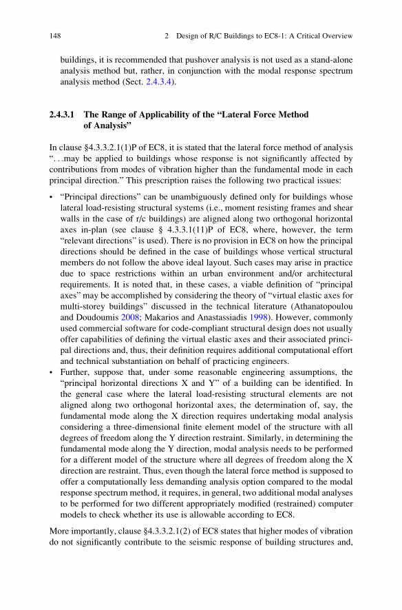
buildings, it is recommended that pushover analysis is not used as a stand-alone
analysis method but, rather, in conjunction with the modal response spectrum
analysis method (Sect. 2.4.3.4).
2.4.3.1 The Range of Applicability of the “Lateral Force Methodof Analysis”
In clause §4.3.3.2.1(1)P of EC8, it is stated that the lateral force method of analysis
“. . .may be applied to buildings whose response is not significantly affected by
contributions from modes of vibration higher than the fundamental mode in each
principal direction.” This prescription raises the following two practical issues:
• “Principal directions” can be unambiguously defined only for buildings whose
lateral load-resisting structural systems (i.e., moment resisting frames and shear
walls in the case of r/c buildings) are aligned along two orthogonal horizontal
axes in-plan (see clause § 4.3.3.1(11)P of EC8, where, however, the term
“relevant directions” is used). There is no provision in EC8 on how the principal
directions should be defined in the case of buildings whose vertical structural
members do not follow the above ideal layout. Such cases may arise in practice
due to space restrictions within an urban environment and/or architectural
requirements. It is noted that, in these cases, a viable definition of “principal
axes” may be accomplished by considering the theory of “virtual elastic axes for
multi-storey buildings” discussed in the technical literature (Athanatopoulou
and Doudoumis 2008; Makarios and Anastassiadis 1998). However, commonly
used commercial software for code-compliant structural design does not usually
offer capabilities of defining the virtual elastic axes and their associated princi-
pal directions and, thus, their definition requires additional computational effort
and technical substantiation on behalf of practicing engineers.
• Further, suppose that, under some reasonable engineering assumptions, the
“principal horizontal directions X and Y” of a building can be identified. In
the general case where the lateral load-resisting structural elements are not
aligned along two orthogonal horizontal axes, the determination of, say, the
fundamental mode along the X direction requires undertaking modal analysis
considering a three-dimensional finite element model of the structure with all
degrees of freedom along the Y direction restraint. Similarly, in determining the
fundamental mode along the Y direction, modal analysis needs to be performed
for a different model of the structure where all degrees of freedom along the X
direction are restraint. Thus, even though the lateral force method is supposed to
offer a computationally less demanding analysis option compared to the modal
response spectrum method, it requires, in general, two additional modal analyses
to be performed for two different appropriately modified (restrained) computer
models to check whether its use is allowable according to EC8.
More importantly, clause §4.3.3.2.1(2) of EC8 states that higher modes of vibration
do not significantly contribute to the seismic response of building structures and,
148 2 Design of R/C Buildings to EC8-1: A Critical Overview
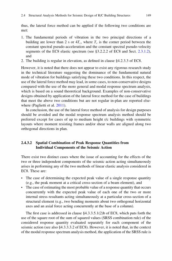
thus, the lateral force method can be applied if the following two conditions are
met:
1. The fundamental periods of vibration in the two principal directions of a
building are lower than 2 s or 4Tc, where Tc is the corner period between the
constant spectral pseudo-acceleration and the constant spectral pseudo-velocity
segments of the EC8 elastic spectrum (see §3.2.2.2 of EC8 and Sect. 2.3.1.2),
and
2. The building is regular in elevation, as defined in clause §4.2.3.3 of EC8.
However, it is noted that there does not appear to exist any rigorous research study
in the technical literature suggesting the dominance of the fundamental natural
mode of vibration for buildings satisfying these two conditions. In this respect, the
use of the lateral force method may lead, in some cases, to non-conservative designs
compared with the use of the more general and modal response spectrum analysis,
which is based on a sound theoretical background. Examples of non-conservative
designs obtained by application of the lateral force method for the case of buildings
that meet the above two conditions but are not regular in-plan are reported else-
where (Paglietti et al. 2011).
In conclusion, the use of the lateral force method of analysis for design purposes
should be avoided and the modal response spectrum analysis method should be
preferred except for cases of up to medium height r/c buildings with symmetric
layouts where moment resisting frames and/or shear walls are aligned along two
orthogonal directions in plan.
2.4.3.2 Spatial Combination of Peak Response Quantities from
Individual Components of the Seismic Action
There exist two distinct cases where the issue of accounting for the effects of the
two or three independent components of the seismic action acting simultaneously
arises in performing any of the two methods of linear elastic analysis considered in
EC8. These are:
• The case of determining the expected peak value of a single response quantity
(e.g., the peak moment at a critical cross-section of a beam element), and
• The case of estimating the most probable value of a response quantity that occurs
concurrently with the expected peak value of each one of the two or more
internal stress resultants acting simultaneously at a particular cross-section of a
structural element (e.g., two bending moments about two orthogonal horizontal
axes and an axial force acting concurrently at the base of a column).
The first case is addressed in clause §4.3.3.5.1(2)b of EC8, which puts forth the
use of the square root of the sum of squared values (SRSS combination rule) of the
considered response quantity evaluated separately for each component of the
seismic action (see also §4.3.3.3.2 of EC8). However, it is noted that, in the context
of the modal response spectrum analysis method, the application of the SRSS rule is
2.4 Structural Analysis Methods for Seismic Design of R/C Building Structures 149
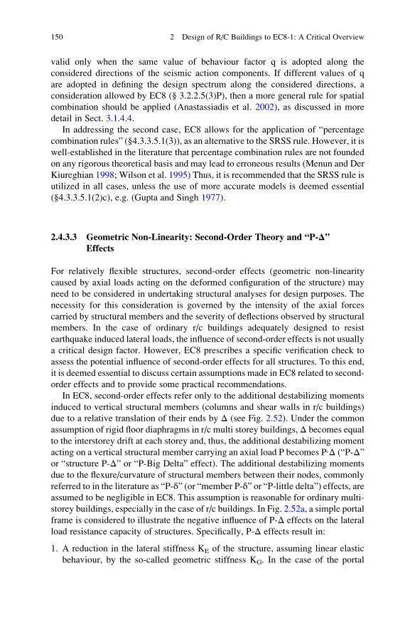
valid only when the same value of behaviour factor q is adopted along the
considered directions of the seismic action components. If different values of q
are adopted in defining the design spectrum along the considered directions, a
consideration allowed by EC8 (§ 3.2.2.5(3)P), then a more general rule for spatial
combination should be applied (Anastassiadis et al. 2002), as discussed in more
detail in Sect. 3.1.4.4.
In addressing the second case, EC8 allows for the application of “percentage
combination rules” (§4.3.3.5.1(3)), as an alternative to the SRSS rule. However, it is
well-established in the literature that percentage combination rules are not founded
on any rigorous theoretical basis and may lead to erroneous results (Menun and Der
Kiureghian 1998; Wilson et al. 1995) Thus, it is recommended that the SRSS rule is
utilized in all cases, unless the use of more accurate models is deemed essential
(§4.3.3.5.1(2)c), e.g. (Gupta and Singh 1977).
2.4.3.3 Geometric Non-Linearity: Second-Order Theory and “P-Δ”Effects
For relatively flexible structures, second-order effects (geometric non-linearity
caused by axial loads acting on the deformed configuration of the structure) may
need to be considered in undertaking structural analyses for design purposes. The
necessity for this consideration is governed by the intensity of the axial forces
carried by structural members and the severity of deflections observed by structural
members. In the case of ordinary r/c buildings adequately designed to resist
earthquake induced lateral loads, the influence of second-order effects is not usually
a critical design factor. However, EC8 prescribes a specific verification check to
assess the potential influence of second-order effects for all structures. To this end,
it is deemed essential to discuss certain assumptions made in EC8 related to second-
order effects and to provide some practical recommendations.
In EC8, second-order effects refer only to the additional destabilizing moments
induced to vertical structural members (columns and shear walls in r/c buildings)
due to a relative translation of their ends by Δ (see Fig. 2.52). Under the common
assumption of rigid floor diaphragms in r/c multi storey buildings, Δ becomes equal
to the interstorey drift at each storey and, thus, the additional destabilizing moment
acting on a vertical structural member carrying an axial load P becomes P∙Δ (“P-Δ”or “structure P-Δ” or “P-Big Delta” effect). The additional destabilizing moments
due to the flexure/curvature of structural members between their nodes, commonly
referred to in the literature as “P-δ” (or “member P-δ” or “P-little delta”) effects, areassumed to be negligible in EC8. This assumption is reasonable for ordinary multi-
storey buildings, especially in the case of r/c buildings. In Fig. 2.52a, a simple portal
frame is considered to illustrate the negative influence of P-Δ effects on the lateral
load resistance capacity of structures. Specifically, P-Δ effects result in:
1. A reduction in the lateral stiffness KE of the structure, assuming linear elastic
behaviour, by the so-called geometric stiffness KG. In the case of the portal
150 2 Design of R/C Buildings to EC8-1: A Critical Overview
frame considered in Fig. 2.52a, KG is equal to P/h (vertical load over the height
of the frame) and, thus, the reduction in stiffness is proportional to the level of
the gravity load, i.e., total stiffness K¼KE-KG¼KE-P/h.
2. A reduction in the seismic base shear Vy (strength) at the yielding displacement
Δy by a factor of 1-θ as shown in Fig. 2.52b, where θ is defined in Fig. 2.52a.
Clearly, this reduction in strength is proportional to both the level of the applied
vertical load and to the yielding displacement.
3. An increase in the negative slope of the post-yield segment in the base shear-
floor deformation diagram (V-Δ diagram), as shown in Fig. 2.52b. The latter
eventually leads to structures of reduced ductility.
Along these lines, EC8 (§ 4.4.2.2(2)) defines the “interstorey drift sensitivity
coefficient” θi at a storey i by the expression
θi ¼ Ptot, iΔi
Vtot, ihið2:14Þ
where:
Ptot.i is the sum of the axial forces carried by all the vertical structural members of
the storey i due to the gravity loads of the seismic design combination of actions;
Vtot.i is the total seismic storey shear at the storey i;Δi¼ qΔel,i is the average interstorey drift of the storey i;Δel,i is the average interstorey drift of the storey i determined by a response
spectrum based linear elastic analysis;
q is the behaviour factor used in the analysis undertaken to compute Δel;
h is the height of storey i.
Fig. 2.52 Influence of P-Δ effects on the lateral stiffness K and the lateral resistance capacity Vy
of a single storey frame (left); destabilizing P-Δ effects in a multi storey frame (right)
2.4 Structural Analysis Methods for Seismic Design of R/C Building Structures 151
– If θ� 0.10, the P-Δ effects are ignored.
– If 0.10< θ� 0.20, the P-Δ effects are accounted for in an approximate manner
by multiplying the response quantities (stress resultants and displacements) by a
factor of 1/(1-θ).– If 0.20< θ� 0.30, an exact second-order analysis must be undertaken.
– If θ> 0.30, a re-design of the structure is required to increase its lateral stiffness
such that θ is reduced to below 0.30.
Note that, in determining the interstorey drift sensitivity coefficient θ using
Eq. (2.14), the values of Ptot.i, Vtot.i, and Δi should occur simultaneously and
correspond to the same load combination. Thus, in the context of modal response
spectrum analysis, θ should be determined by application of Eq. (2.14) for each
considered direction of seismic action and each vibration mode followed by
application of a modal and spatial combination rule (see also Sect. 3.2.1). Clearly,
this is not a trivial task if automated structural design software is not available.
Further, it is noted that the ratio θ as determined by Eq. (2.14) is accurate only
for planar frames with a predominantly shear-type of deflected shape in elevation
under static loads (McGregor and Hage 1977). The application of the above
formula for coupled frame-shear wall structural systems may yield large
non-conservative deviations from the true value of θ, especially when the product
λΗ is less than 6, where H is the total height of the building, λ2¼GAs/EI, and GAs,
EI are the total shear and flexural stiffness, respectively, of the considered coupled
system treated as a continuous structure comprising a purely shear sub-system and a
purely flexural sub-system. For example, if λΗ¼ 1, the value of θ computed from
Eq. (2.14) will deviate by 50 % from the true value θ. In general, Eq. (2.14) is not
valid for three-dimensional asymmetric in plan building structures.
The aforementioned problems of accuracy related to the determination of the
interstorey drift sensitivity coefficient θ defined in Eq. (2.14) can be readily
circumvented by making use of finite element structural analysis software capable
of performing reliably static second-order analysis. In case such software is avail-
able, it is herein proposed to use an elastic stability index expressed by
θe ¼ P
Pcr,elð2:15Þ
as a basis of an alternative verification check against second-order effects. In the
above equation, P is the total gravity load of the seismic design combination of
actions and Pcr,el is the critical buckling load of the structure following the well-
known theory of stability of structures under static loads.
The expression in Eq. (2.15) applies universally to all types of lateral load
resisting structural systems. Further, the index θe is a property uniquely defined
for each structure since it depends only on the stiffness of the structure and on the
distribution of the gravitational loads, while it is independent of the assumed
horizontal seismic loads. Finally, the influence of the inelastic behaviour (material
non-linearity) regulated by the behaviour factor q in the context of the EC8 can be
152 2 Design of R/C Buildings to EC8-1: A Critical Overview
taken into account by considering the product θe∙q as is prescribed for all cases of
displacement response quantities (§ 4.3.4(1)P of EC8). Hence, it is herein proposed
to consider the following criterion for checking against second-order phenomena
instead of that of Eq. (2.14)
θ ¼ qθe � 0:10 ð2:16Þ
where θe is defined in Eq. (2.14).
It is recognised that the above criterion relies on a simple static second-order
analysis which, however, can be considered sufficiently accurate for ordinary r/c
buildings. Undertaking more sophisticated types of second-order analyses (i.e.,
accounting for material non-linearity and/or the dynamic nature of the input seismic
action) would not be reasonable within the context of an “equivalent linear” type of
analysis adopted by codes of practice like EC8, where material non-linearity is
crudely taken into account through a single scalar (i.e., the behaviour factor q) and a
simple flat reduction of all structural elements’ stiffness properties.
2.4.3.4 Material Non-Linearity: The Inelastic Static “Pushover”
Analysis
For all practical reasons discussed in Sect. 2.4.1, the use of the inelastic response
history analysis is rarely considered in “routine” seismic design or assessment of
ordinary r/c building structures. However, inelastic static analysis methods are
extensively used in practice and, in fact, they are considered the preferable methods
for the seismic assessment of existing (code-deficient) structures. Notably, EC8
prescribes the use of a particular inelastic static analysis method not only for
seismic assessment of existing structures, but also for determination of the
overstrength ratio involved in the calculation of the q factor value for design
using equivalent linear analysis methods (see also Sect. 3.1.5). Furthermore, it is
the first seismic code of practice worldwide to allow for the use of such an analysis
method as an alternative to the standard linear elastic methods of analysis (clause
§4.3.3.4.2.1(d) of EC8) to account for material post-yield behaviour (see also
Sect. 2.4.1.2). To this end, it is herein deemed necessary to discuss in some detail
the EC8 prescribed static inelastic method, although it is not utilized in the ensuing
chapters of this book.
The so-called “non-linear static (pushover) analysis” is described in clause
§4.3.3.4.2 and in the Informative Annex B of EC8. It is an inelastic static analysis
method developed by Fajfar (Fajfar 2000). The detailed steps of the method are
presented in Appendix B of this book. In accounting for material non-linearity, a
bilinear force-deformation (or moment-rotation/curvature) relationship with no
strengthening in the post-yield range (§4.3.3.4.1(2) and (3)), that is, an elastic-
perfectly plastic model, is allowed to be used (at minimum) at the structural
member level (see, e.g., Fig. 1.9). Conveniently, this model requires knowledge
of only the pre-yield stiffness (cracked section is assumed as per Sect. 2.3.2.1), the
2.4 Structural Analysis Methods for Seismic Design of R/C Building Structures 153
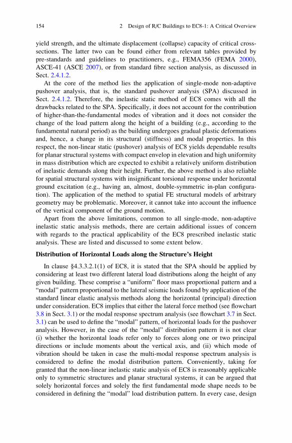
yield strength, and the ultimate displacement (collapse) capacity of critical cross-
sections. The latter two can be found either from relevant tables provided by
pre-standards and guidelines to practitioners, e.g., FEMA356 (FEMA 2000),
ASCE-41 (ASCE 2007), or from standard fibre section analysis, as discussed in
Sect. 2.4.1.2.
At the core of the method lies the application of single-mode non-adaptive
pushover analysis, that is, the standard pushover analysis (SPA) discussed in
Sect. 2.4.1.2. Therefore, the inelastic static method of EC8 comes with all the
drawbacks related to the SPA. Specifically, it does not account for the contribution
of higher-than-the-fundamental modes of vibration and it does not consider the
change of the load pattern along the height of a building (e.g., according to the
fundamental natural period) as the building undergoes gradual plastic deformations
and, hence, a change in its structural (stiffness) and modal properties. In this
respect, the non-linear static (pushover) analysis of EC8 yields dependable results
for planar structural systems with compact envelop in elevation and high uniformity
in mass distribution which are expected to exhibit a relatively uniform distribution
of inelastic demands along their height. Further, the above method is also reliable
for spatial structural systems with insignificant torsional response under horizontal
ground excitation (e.g., having an, almost, double-symmetric in-plan configura-
tion). The application of the method to spatial FE structural models of arbitrary
geometry may be problematic. Moreover, it cannot take into account the influence
of the vertical component of the ground motion.
Apart from the above limitations, common to all single-mode, non-adaptive
inelastic static analysis methods, there are certain additional issues of concern
with regards to the practical applicability of the EC8 prescribed inelastic static
analysis. These are listed and discussed to some extent below.
Distribution of Horizontal Loads along the Structure’s Height
In clause §4.3.3.2.1(1) of EC8, it is stated that the SPA should be applied by
considering at least two different lateral load distributions along the height of any
given building. These comprise a “uniform” floor mass proportional pattern and a
“modal” pattern proportional to the lateral seismic loads found by application of the
standard linear elastic analysis methods along the horizontal (principal) direction
under consideration. EC8 implies that either the lateral force method (see flowchart
3.8 in Sect. 3.1) or the modal response spectrum analysis (see flowchart 3.7 in Sect.
3.1) can be used to define the “modal” pattern, of horizontal loads for the pushover
analysis. However, in the case of the “modal” distribution pattern it is not clear
(i) whether the horizontal loads refer only to forces along one or two principal
directions or include moments about the vertical axis, and (ii) which mode of
vibration should be taken in case the multi-modal response spectrum analysis is
considered to define the modal distribution pattern. Conveniently, taking for
granted that the non-linear inelastic static analysis of EC8 is reasonably applicable
only to symmetric structures and planar structural systems, it can be argued that
solely horizontal forces and solely the first fundamental mode shape needs to be
considered in defining the “modal” load distribution pattern. In every case, design
154 2 Design of R/C Buildings to EC8-1: A Critical Overview
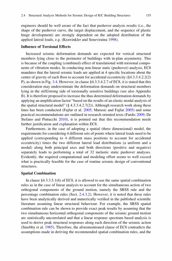
engineers should be well aware of the fact that pushover analysis results (i.e., the
shape of the pushover curve, the target displacement, and the sequence of plastic
hinge development) are strongly dependent on the adopted distribution of the
applied lateral loads, e.g. (Krawinkler and Seneviratna 1998).
Influence of Torsional Effects
Increased seismic deformation demands are expected for vertical structural
members lying close to the perimeter of buildings with in-plan asymmetry. This
is because of the coupling (combined) effect of translational with torsional compo-
nents of vibration modes. In conducting non-linear static (pushover) analysis, EC8
mandates that the lateral seismic loads are applied at 4 specific locations about the
center of gravity of each floor to account for accidental eccentricity (§4.3.3.4.2.2(2)
P), as shown in Fig. 3.4. However, in clause §4.3.3.4.2.7 of EC8, it is stated that this
consideration may underestimate the deformation demands on structural members
lying in the stiff/strong side of torsionally sensitive buildings (see also Appendix
B). It is therefore proposed to increase the thus determined deformation demands by
applying an amplification factor “based on the results of an elastic modal analysis of
the spatial structural model” (§ 4.3.3.4.2.7(2)). Although research work along these
lines has been conducted (Fajfar et al. 2005; Marusic and Fajfar 2005) and some
practical recommendations are outlined in research oriented texts (Fardis 2009; De
Stefano and Pintucchi 2010), it is pointed out that this recommendation needs
further justification and explanation within EC8.
Furthermore, in the case of adopting a spatial (three dimensional) model, the
requirements for considering 4 different sets of points where lateral loads need to be
applied (corresponding to 4 different mass positions to account for accidental
eccentricity) times the two different lateral load distributions (a uniform and a
modal) along both principal axes and both directions (positive and negative)
separately leads to performing a total of 32 inelastic static pushover analyses.
Evidently, the required computational and modeling effort seems to well exceed
what is practically feasible for the case of routine seismic design of conventional
structures.
Spatial Combination
In clause §4.3.3.5.1(6) of EC8, it is allowed to use the same spatial combination
rules as in the case of linear analysis to account for the simultaneous action of two
orthogonal components of the ground motion, namely the SRSS rule and the
percentage combination rules (Sect. 2.4.3.2). However, it is noted that these rules
have been analytically derived and numerically verified in the published scientific
literature assuming linear structural behaviour. For example, the SRSS spatial
combination rule can be shown to provide exact peak results by assuming that the
two simultaneous horizontal orthogonal components of the seismic ground motion
are statistically uncorrelated and that a linear response spectrum based analysis is
used to derive peak structural responses along each direction of the seismic action
(Smebby et al. 1985). Therefore, the aforementioned clause of EC8 contradicts the
assumptions made in deriving the recommended spatial combination rules, and the
2.4 Structural Analysis Methods for Seismic Design of R/C Building Structures 155
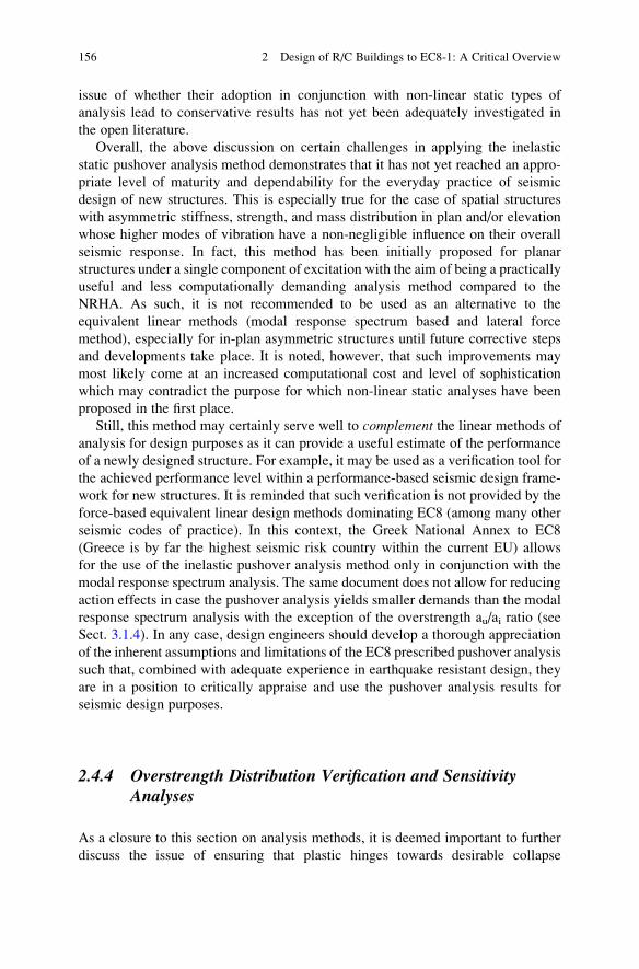
issue of whether their adoption in conjunction with non-linear static types of
analysis lead to conservative results has not yet been adequately investigated in
the open literature.
Overall, the above discussion on certain challenges in applying the inelastic
static pushover analysis method demonstrates that it has not yet reached an appro-
priate level of maturity and dependability for the everyday practice of seismic
design of new structures. This is especially true for the case of spatial structures
with asymmetric stiffness, strength, and mass distribution in plan and/or elevation
whose higher modes of vibration have a non-negligible influence on their overall
seismic response. In fact, this method has been initially proposed for planar
structures under a single component of excitation with the aim of being a practically
useful and less computationally demanding analysis method compared to the
NRHA. As such, it is not recommended to be used as an alternative to the
equivalent linear methods (modal response spectrum based and lateral force
method), especially for in-plan asymmetric structures until future corrective steps
and developments take place. It is noted, however, that such improvements may
most likely come at an increased computational cost and level of sophistication
which may contradict the purpose for which non-linear static analyses have been
proposed in the first place.
Still, this method may certainly serve well to complement the linear methods of
analysis for design purposes as it can provide a useful estimate of the performance
of a newly designed structure. For example, it may be used as a verification tool for
the achieved performance level within a performance-based seismic design frame-
work for new structures. It is reminded that such verification is not provided by the
force-based equivalent linear design methods dominating EC8 (among many other
seismic codes of practice). In this context, the Greek National Annex to EC8
(Greece is by far the highest seismic risk country within the current EU) allows
for the use of the inelastic pushover analysis method only in conjunction with the
modal response spectrum analysis. The same document does not allow for reducing
action effects in case the pushover analysis yields smaller demands than the modal
response spectrum analysis with the exception of the overstrength au/ai ratio (see
Sect. 3.1.4). In any case, design engineers should develop a thorough appreciation
of the inherent assumptions and limitations of the EC8 prescribed pushover analysis
such that, combined with adequate experience in earthquake resistant design, they
are in a position to critically appraise and use the pushover analysis results for
seismic design purposes.
2.4.4 Overstrength Distribution Verification and SensitivityAnalyses
As a closure to this section on analysis methods, it is deemed important to further
discuss the issue of ensuring that plastic hinges towards desirable collapse
156 2 Design of R/C Buildings to EC8-1: A Critical Overview
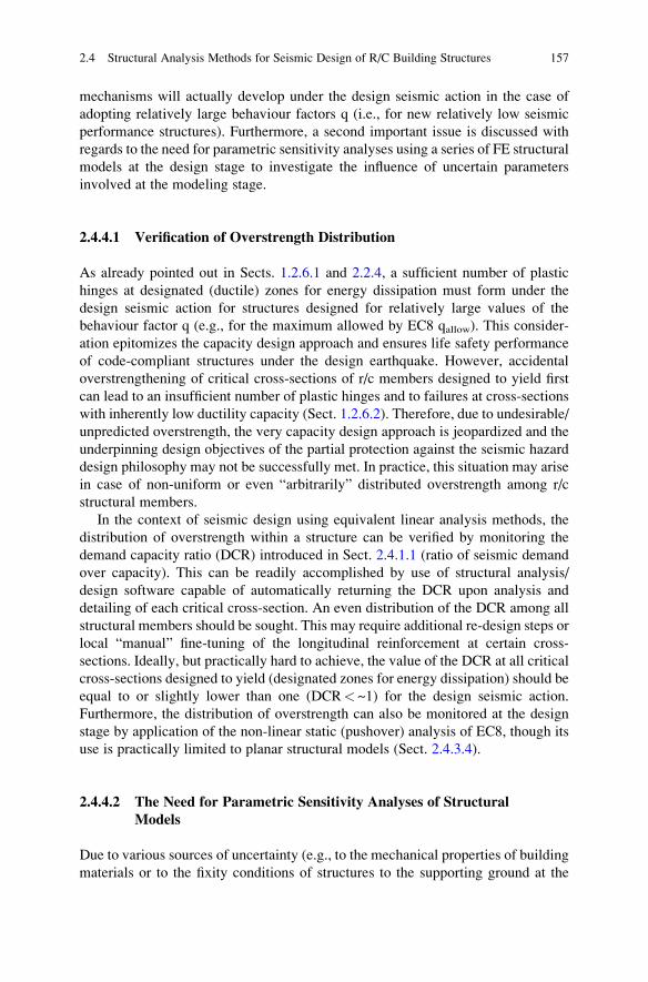
mechanisms will actually develop under the design seismic action in the case of
adopting relatively large behaviour factors q (i.e., for new relatively low seismic
performance structures). Furthermore, a second important issue is discussed with
regards to the need for parametric sensitivity analyses using a series of FE structural
models at the design stage to investigate the influence of uncertain parameters
involved at the modeling stage.
2.4.4.1 Verification of Overstrength Distribution
As already pointed out in Sects. 1.2.6.1 and 2.2.4, a sufficient number of plastic
hinges at designated (ductile) zones for energy dissipation must form under the
design seismic action for structures designed for relatively large values of the
behaviour factor q (e.g., for the maximum allowed by EC8 qallow). This consider-
ation epitomizes the capacity design approach and ensures life safety performance
of code-compliant structures under the design earthquake. However, accidental
overstrengthening of critical cross-sections of r/c members designed to yield first
can lead to an insufficient number of plastic hinges and to failures at cross-sections
with inherently low ductility capacity (Sect. 1.2.6.2). Therefore, due to undesirable/
unpredicted overstrength, the very capacity design approach is jeopardized and the
underpinning design objectives of the partial protection against the seismic hazard
design philosophy may not be successfully met. In practice, this situation may arise
in case of non-uniform or even “arbitrarily” distributed overstrength among r/c
structural members.
In the context of seismic design using equivalent linear analysis methods, the
distribution of overstrength within a structure can be verified by monitoring the
demand capacity ratio (DCR) introduced in Sect. 2.4.1.1 (ratio of seismic demand
over capacity). This can be readily accomplished by use of structural analysis/
design software capable of automatically returning the DCR upon analysis and
detailing of each critical cross-section. An even distribution of the DCR among all
structural members should be sought. This may require additional re-design steps or
local “manual” fine-tuning of the longitudinal reinforcement at certain cross-
sections. Ideally, but practically hard to achieve, the value of the DCR at all critical
cross-sections designed to yield (designated zones for energy dissipation) should be
equal to or slightly lower than one (DCR< ~1) for the design seismic action.
Furthermore, the distribution of overstrength can also be monitored at the design
stage by application of the non-linear static (pushover) analysis of EC8, though its
use is practically limited to planar structural models (Sect. 2.4.3.4).
2.4.4.2 The Need for Parametric Sensitivity Analyses of Structural
Models
Due to various sources of uncertainty (e.g., to the mechanical properties of building
materials or to the fixity conditions of structures to the supporting ground at the
2.4 Structural Analysis Methods for Seismic Design of R/C Building Structures 157
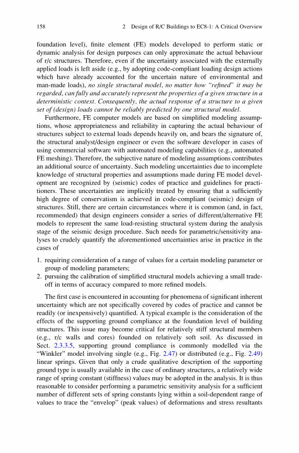
foundation level), finite element (FE) models developed to perform static or
dynamic analysis for design purposes can only approximate the actual behaviour
of r/c structures. Therefore, even if the uncertainty associated with the externally
applied loads is left aside (e.g., by adopting code-compliant loading design actions
which have already accounted for the uncertain nature of environmental and
man-made loads), no single structural model, no matter how “refined” it may beregarded, can fully and accurately represent the properties of a given structure in adeterministic context. Consequently, the actual response of a structure to a givenset of (design) loads cannot be reliably predicted by one structural model.
Furthermore, FE computer models are based on simplified modeling assump-
tions, whose appropriateness and reliability in capturing the actual behaviour of
structures subject to external loads depends heavily on, and bears the signature of,
the structural analyst/design engineer or even the software developer in cases of
using commercial software with automated modeling capabilities (e.g., automated
FE meshing). Therefore, the subjective nature of modeling assumptions contributes
an additional source of uncertainty. Such modeling uncertainties due to incomplete
knowledge of structural properties and assumptions made during FE model devel-
opment are recognized by (seismic) codes of practice and guidelines for practi-
tioners. These uncertainties are implicitly treated by ensuring that a sufficiently
high degree of conservatism is achieved in code-compliant (seismic) design of
structures. Still, there are certain circumstances where it is common (and, in fact,
recommended) that design engineers consider a series of different/alternative FE
models to represent the same load-resisting structural system during the analysis
stage of the seismic design procedure. Such needs for parametric/sensitivity ana-
lyses to crudely quantify the aforementioned uncertainties arise in practice in the
cases of
1. requiring consideration of a range of values for a certain modeling parameter or
group of modeling parameters;
2. pursuing the calibration of simplified structural models achieving a small trade-
off in terms of accuracy compared to more refined models.
The first case is encountered in accounting for phenomena of significant inherent
uncertainty which are not specifically covered by codes of practice and cannot be
readily (or inexpensively) quantified. A typical example is the consideration of the
effects of the supporting ground compliance at the foundation level of building
structures. This issue may become critical for relatively stiff structural members
(e.g., r/c walls and cores) founded on relatively soft soil. As discussed in
Sect. 2.3.3.5, supporting ground compliance is commonly modelled via the
“Winkler” model involving single (e.g., Fig. 2.47) or distributed (e.g., Fig. 2.49)
linear springs. Given that only a crude qualitative description of the supporting
ground type is usually available in the case of ordinary structures, a relatively wide
range of spring constant (stiffness) values may be adopted in the analysis. It is thus
reasonable to consider performing a parametric sensitivity analysis for a sufficient
number of different sets of spring constants lying within a soil-dependent range of
values to trace the “envelop” (peak values) of deformations and stress resultants
158 2 Design of R/C Buildings to EC8-1: A Critical Overview
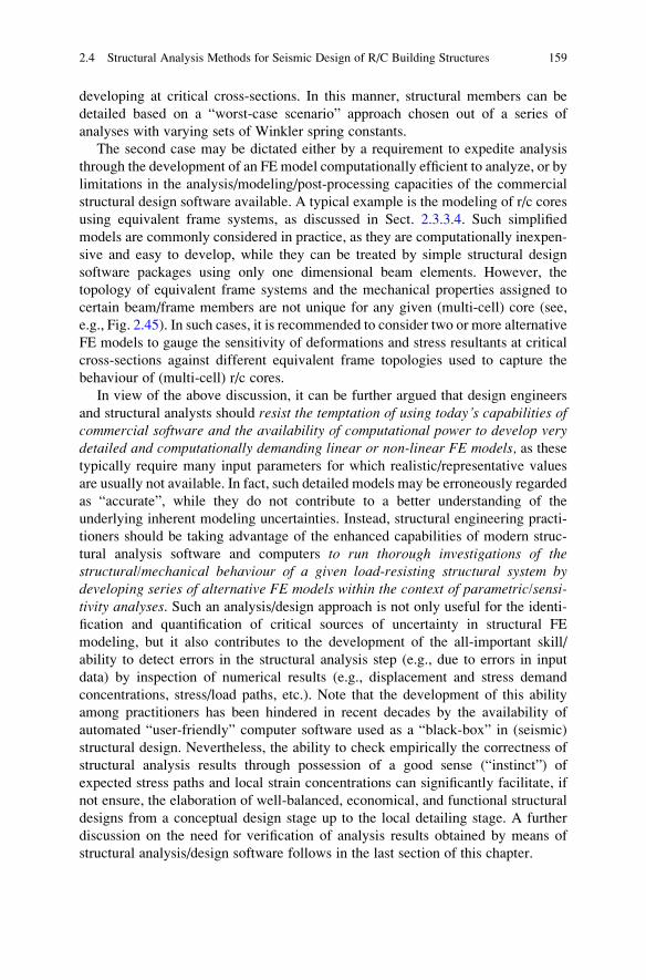
developing at critical cross-sections. In this manner, structural members can be
detailed based on a “worst-case scenario” approach chosen out of a series of
analyses with varying sets of Winkler spring constants.
The second case may be dictated either by a requirement to expedite analysis
through the development of an FE model computationally efficient to analyze, or by
limitations in the analysis/modeling/post-processing capacities of the commercial
structural design software available. A typical example is the modeling of r/c cores
using equivalent frame systems, as discussed in Sect. 2.3.3.4. Such simplified
models are commonly considered in practice, as they are computationally inexpen-
sive and easy to develop, while they can be treated by simple structural design
software packages using only one dimensional beam elements. However, the
topology of equivalent frame systems and the mechanical properties assigned to
certain beam/frame members are not unique for any given (multi-cell) core (see,
e.g., Fig. 2.45). In such cases, it is recommended to consider two or more alternative
FE models to gauge the sensitivity of deformations and stress resultants at critical
cross-sections against different equivalent frame topologies used to capture the
behaviour of (multi-cell) r/c cores.
In view of the above discussion, it can be further argued that design engineers
and structural analysts should resist the temptation of using today’s capabilities ofcommercial software and the availability of computational power to develop verydetailed and computationally demanding linear or non-linear FE models, as thesetypically require many input parameters for which realistic/representative values
are usually not available. In fact, such detailed models may be erroneously regarded
as “accurate”, while they do not contribute to a better understanding of the
underlying inherent modeling uncertainties. Instead, structural engineering practi-
tioners should be taking advantage of the enhanced capabilities of modern struc-
tural analysis software and computers to run thorough investigations of thestructural/mechanical behaviour of a given load-resisting structural system bydeveloping series of alternative FE models within the context of parametric/sensi-tivity analyses. Such an analysis/design approach is not only useful for the identi-
fication and quantification of critical sources of uncertainty in structural FE
modeling, but it also contributes to the development of the all-important skill/
ability to detect errors in the structural analysis step (e.g., due to errors in input
data) by inspection of numerical results (e.g., displacement and stress demand
concentrations, stress/load paths, etc.). Note that the development of this ability
among practitioners has been hindered in recent decades by the availability of
automated “user-friendly” computer software used as a “black-box” in (seismic)
structural design. Nevertheless, the ability to check empirically the correctness of
structural analysis results through possession of a good sense (“instinct”) of
expected stress paths and local strain concentrations can significantly facilitate, if
not ensure, the elaboration of well-balanced, economical, and functional structural
designs from a conceptual design stage up to the local detailing stage. A further
discussion on the need for verification of analysis results obtained by means of
structural analysis/design software follows in the last section of this chapter.
2.4 Structural Analysis Methods for Seismic Design of R/C Building Structures 159
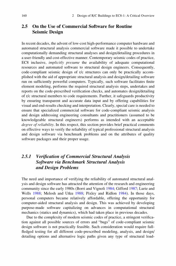
2.5 On the Use of Commercial Software for RoutineSeismic Design
In recent decades, the advent of low-cost high-performance computer hardware and
automated structural analysis commercial software made it possible to undertake
computationally demanding structural analyses and design/detailing procedures in
a user-friendly and cost-effective manner. Contemporary seismic codes of practice,
EC8 inclusive, implicitly presume the availability of adequate computational
resources and automated software to structural design engineers. Consequently,
code-compliant seismic design of r/c structures can only be practically accom-
plished with the aid of appropriate structural analysis and design/detailing software
run on sufficiently powerful computers. Typically, such software facilitates finite
element modeling, performs the required structural analysis steps, undertakes and
reports on the code-prescribed verification checks, and automates design/detailing
of r/c structural members to code requirements. Further, it safeguards productivity
by ensuring transparent and accurate data input and by offering capabilities for
visual and end-results checking and interpretation. Clearly, special care is needed to
ensure that specialized commercial software for code-compliant seismic analysis
and design addressing engineering consultants and practitioners (assumed to be
knowledgeable structural engineers) performs as intended with an acceptable
degree of reliability. In this respect, this section provides brief practical comments
on effective ways to verify the reliability of typical professional structural analysis
and design software via benchmark problems and on the attributes of quality
software packages and their proper usage.
2.5.1 Verification of Commercial Structural AnalysisSoftware via Benchmark Structural Analysisand Design Problems
The need and importance of verifying the reliability of automated structural anal-
ysis and design software has attracted the attention of the research and engineering
community since the early 1980s (Borri and Vignoli 1984; Gifford 1987; Lurie and
Wells 1988; Melosh and Utku 1988; Pixley and Ridlon 1984). In those days,
personal computers became relatively affordable, offering the opportunity for
computer-aided structural analysis and design. This was achieved by developing
purpose-made software capitalizing on advances in computational structural
mechanics (statics and dynamics), which had taken place in previous decades.
Due to the complexity of modern seismic codes of practice, a stringent verifica-
tion against all possible sources of errors and “bugs” of code-compliant seismic
design software is not practically feasible. Such consideration would require full-
fledged testing for all different code-prescribed modeling, analysis, and design/
detailing options and alternative logic paths given any type of structural load-
160 2 Design of R/C Buildings to EC8-1: A Critical Overview
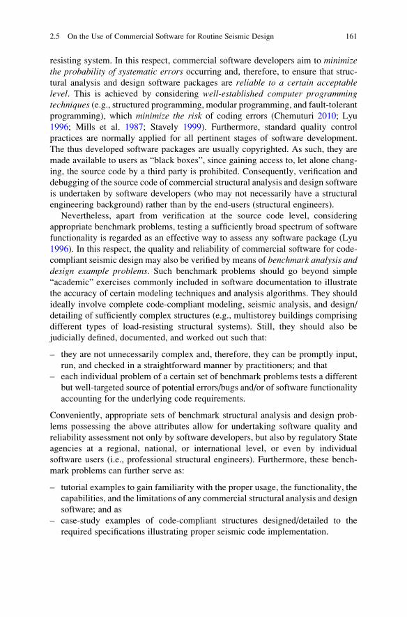
resisting system. In this respect, commercial software developers aim to minimizethe probability of systematic errors occurring and, therefore, to ensure that struc-
tural analysis and design software packages are reliable to a certain acceptablelevel. This is achieved by considering well-established computer programmingtechniques (e.g., structured programming, modular programming, and fault-tolerant
programming), which minimize the risk of coding errors (Chemuturi 2010; Lyu
1996; Mills et al. 1987; Stavely 1999). Furthermore, standard quality control
practices are normally applied for all pertinent stages of software development.
The thus developed software packages are usually copyrighted. As such, they are
made available to users as “black boxes”, since gaining access to, let alone chang-
ing, the source code by a third party is prohibited. Consequently, verification and
debugging of the source code of commercial structural analysis and design software
is undertaken by software developers (who may not necessarily have a structural
engineering background) rather than by the end-users (structural engineers).
Nevertheless, apart from verification at the source code level, considering
appropriate benchmark problems, testing a sufficiently broad spectrum of software
functionality is regarded as an effective way to assess any software package (Lyu
1996). In this respect, the quality and reliability of commercial software for code-
compliant seismic design may also be verified by means of benchmark analysis anddesign example problems. Such benchmark problems should go beyond simple
“academic” exercises commonly included in software documentation to illustrate
the accuracy of certain modeling techniques and analysis algorithms. They should
ideally involve complete code-compliant modeling, seismic analysis, and design/
detailing of sufficiently complex structures (e.g., multistorey buildings comprising
different types of load-resisting structural systems). Still, they should also be
judicially defined, documented, and worked out such that:
– they are not unnecessarily complex and, therefore, they can be promptly input,
run, and checked in a straightforward manner by practitioners; and that
– each individual problem of a certain set of benchmark problems tests a different
but well-targeted source of potential errors/bugs and/or of software functionality
accounting for the underlying code requirements.
Conveniently, appropriate sets of benchmark structural analysis and design prob-
lems possessing the above attributes allow for undertaking software quality and
reliability assessment not only by software developers, but also by regulatory State
agencies at a regional, national, or international level, or even by individual
software users (i.e., professional structural engineers). Furthermore, these bench-
mark problems can further serve as:
– tutorial examples to gain familiarity with the proper usage, the functionality, the
capabilities, and the limitations of any commercial structural analysis and design
software; and as
– case-study examples of code-compliant structures designed/detailed to the
required specifications illustrating proper seismic code implementation.
2.5 On the Use of Commercial Software for Routine Seismic Design 161
However, it should be recognized that the development of appropriate sets of
benchmark structural design problems is a formidable task that requires knowledge
of computational mechanics, structural analysis and dynamics, design and detailing
of r/c structures for earthquake resistance, and computer programming, along with a
thorough appreciation of the requirements of codes of practice and their intended
practical implementation. Moreover, their solution requires the use of proper
software and computer coding. In this regard, dependable benchmark problems
are difficult to develop for individual structural design engineers alone This task is
usually accomplished by the involvement of the research community and/or of
experienced and respectable engineering consultants under the auspices of national
or international regulatory agencies.
Along these lines, the three numerical examples provided in Chap. 4 of this book
can be viewed as prototypes of benchmark seismic analysis and design problems of
r/c building structures compliant with the EC8 and EC2. Therefore, they may be
used not only as instructive case-studies to illustrate EC8-compliant seismic anal-
ysis and design but also as benchmark problems to partially check the “correctness”
of commercial seismic structural analysis software and design of r/c building
structures according to Eurocodes. In fact, these three example problems are
based partly on a large set of purpose-developed benchmark structural analysis
problems according to the late Greek Seismic Code EAK2000 (Earthquake Plan-
ning and Protection Organization (EPPO) 2000a) in the frame of a research project
funded by the Hellenic Earthquake Planning and Protection Organization
(Avramidis et al. 2005) and partly on a set of benchmark problems (Sextos
et al. 2008) compliant with the latest Greek Reinforced Concrete Code
ΕKΟΣ2000 (Earthquake Planning and Protection Organization (EPPO) 2000b).
Incidentally, the above sets of benchmark problems are free to view and download
from www.ec8examples.gr (in Greek).
2.5.2 Desirable Attributes and Use of Good Quality Software
The quality of professional software for code-compliant seismic design of r/c
structures can be verified and gauged against different criteria, including:
(a) The correct implementation (coding) of structural analysis algorithms and
code-prescribed design verification checks and detailing of structural
members;
(b) The completeness in accounting for all particular verification checks and
relevant requirements prescribed by structural codes of practice;
(c) The rationale, validity, and applicability of the default simplification assump-tions made in the modeling and analysis stages; and
(d) The ease of use, including the graphical interface, the visualization of input
data and output results, and the accompanied documentation.
162 2 Design of R/C Buildings to EC8-1: A Critical Overview
As discussed in the previous section, the “correctness” of any software package
in terms of analysis results, data post-processing, implementation of code-
prescribed verification checks, and detailing of r/c members according to seismic
code rules and requirements can be effectively assessed by relying on standard sets
of purpose-developed benchmark analysis and design problems. In cases where
only a particular (partial) software verification check is deemed necessary, targeted
“hand-calculations” or calculations readily automated in a spreadsheet format may
suffice. Further, the level of completeness by which a particular structural design
software package covers and fulfils the requirements of a given seismic code of
practice can also be assessed by case-dependent benchmark design examples.
However, for such an assessment, a thorough appreciation of seismic code pre-
scriptions is required as well. To this aim, the implementation flowcharts included
in Chap. 3 provide a solid basis for commercial software verification in terms of
completeness and coverage of the EC8 code for the seismic design of ordinary r/c
structures.
Typical commercial software comes with various default simplification assump-
tions pertaining to the modeling and analysis stages aiming to expedite routine
code-compliant seismic design. Therefore, unlike the case of research-oriented
fully customizable software, analysis results obtained by means of commercial
structural design programs may be biased and dependent on the inherent assump-
tions made. In this regard, it is normal to expect that different commercial software
packages yield different analysis results, which might impact detailing of certain
critical structural members, for the same input structural system and loading
(Fig. 2.53a). For “good-quality” software (in terms of correctness, completeness,
and default assumptions), the observed differences in the final structural designs
(e.g., required longitudinal reinforcement ratios at critical cross-sections) should be
well within an acceptable engineering precision covered by the inherent conserva-
tism of seismic codes of practice. Still, in principle, all default modeling and
analysis assumptions made should be explicitly stated and described with sufficient
detail in the accompanying documentation of quality commercial structural analy-
sis/design programs, even if these assumptions are not amenable to user-defined
changes. This consideration ensures transparency and safeguards software users
(structural engineering practitioners) from developing erroneous presumptions on
the level of accuracy achieved by certain modeling and analysis techniques which
may be acceptable for routine seismic design of ordinary structures but may not be
applicable to more demanding/specialized seismic design scenarios.
Lastly, the “ease of use” criterion is rather subjective and, to a great extent, a
matter of personal preference. Nevertheless, the current consensus suggests that
certain standard features, such as user-friendly graphical interface for data input,
visualization tools to inspect output analysis and detailing results, transparency in
assumptions made and steps followed, completeness of accompanying manuals and
software documentation including tutorials and benchmark problems, are quite
desirable and beneficial to practising engineers.
Apart from the quality of structural analysis and design software itself, it is
important to note that commercial seismic design software must always be used
2.5 On the Use of Commercial Software for Routine Seismic Design 163
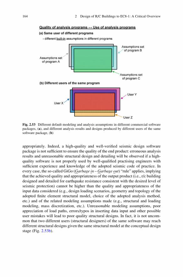
appropriately. Indeed, a high-quality and well-verified seismic design software
package is not sufficient to ensure the quality of the end product: erroneous analysis
results and unreasonable structural design and detailing will be observed if a high-
quality software is not properly used by well-qualified practising engineers with
sufficient experience and knowledge of the adopted seismic code of practice. In
every case, the so-called GiGo (Garbage in – Garbage out) “rule” applies, implying
that the achieved quality and appropriateness of the output product (i.e., r/c building
designed and detailed for earthquake resistance consistent with the desired level of
seismic protection) cannot be higher than the quality and appropriateness of the
input data considered (e.g., design loading scenarios, geometry and topology of the
adopted finite element structural model, choice of the adopted analysis method,
etc.) and of the related modeling assumptions made (e.g., structural and loading
modeling, mass discretization, etc.). Unreasonable modeling assumptions, poor
appreciation of load paths, errors/typos in inserting data input and other possible
user mistakes will lead to poor quality structural designs. In fact, it is not uncom-
mon that two different users (structural designers) of the same software may reach
different structural designs given the same structural model at the conceptual design
stage (Fig. 2.53b).
Fig. 2.53 Different default modeling and analysis assumptions in different commercial software
packages, (a), and different analysis results and designs produced by different users of the same
software package, (b)
164 2 Design of R/C Buildings to EC8-1: A Critical Overview
References
Anastassiadis K, Avramidis IE, Panetsos P (2002) Concurrent design forces in structures under
three-component orthotropic seismic excitation. Earthq Spectra 18:1–17
Anastassiadis K, Avramidis IE, Athanatopoulou AM (2003) Critical comments on Eurocode
8, Draft no.5, Part I, Sections 3 and 4. fib symposium on concrete structures in seismic regions,
6–8 May, Athens/Greece
Antoniou S, Pinho R (2002) Advantages and limitations of adaptive and non adaptive force-based
pushover procedures. J Earthq Eng, ATC and EPPO 8:497–522
Applied Technology Council (ATC) (1996) Seismic evaluation and retrofit of concrete buildings,
ATC-40, Redwood City
Arnold C (2001) Architectural considerations. In: Naeim F (ed) The Seismic Design Handbook,
2nd edn. Kluwer Academic Services, Boston, pp 275–326
Arnold C (2006) Seismic issues in architectural design. Designing for earthquakes. A manual for
architects. FEMA 454/Dec 2006, risk management series. NEHRP, Oakland, CA, pp 1–54
ASCE (2007) ASCE/SEI standard 41–06, seismic rehabilitation of existing buildings. American
Society of Civil Engineers, Reston
Athanatopoulou AM, Avramidis IE (2008) Evaluation of EC8 provisions concerning the analysis
of spatial building structures using two planar models. 5th Eurropean workshop on the seismic
behaviour irregular complex structure, Catania, Italy, pp 285–297
Athanatopoulou AM, Doudoumis IN (2008) Principal directions under lateral loading in
multistorey asymmetric buildings. Struct Des Tall Spec Build 17:773–794. doi:10.1002/tal
Avramidis IE (1991) Zur Kritik des aquivalenten Rahmenmodells fur Wandscheiben und
Hochhauskerne. DIE BAUTECHNIK 68:275–285
Avramidis IE, Manolis GD, Andreadakis MG (1995) PADEX – a preliminary antiseismic design
expert system. In: Pahl PJ, Werner H (eds) Computing civil building engineering. Balkema,
Rotterdam, pp 215–220
Avramidis IE, Anastassiadis K, Athanatopoulou A, Morfidis K (2005) Benchmark numerical
examples to support correct application of the Greek anti-seismic code and facilitate control
of professional software (in Greek). Aivazis Editions, Thessaloniki, Greece
Berrais A (2005) A knowledge-based expert system for earthquake resistant design of reinforced
concrete buildings. Expert Syst Appl 28:519–530
Bisch P, Carvalho E, Degee H, Fajfar P, Fardis M, Franchin P, Kreslin M, Pecker A, Pinto P,
Plumier A, Somja H, Tsionis G (2012) Eurocode 8: seismic design of buildings worked
examples, JRC technical report. Publications Office of the European Union/Joint Research
Centre, Luxembourg
Borri A, Vignoli A (1984) Micro-computer-aided design: a critical discussion of the reliability of
programs of current use. In: Proceedings of the international conference on engineering
software microcomputing. Pineridge Press, Swansea, pp 239–250
CEN (2002) European Standard EN1990. Eurocode 0: basis of structural design. Committee for
Standarization. Brussels
CEN (2004) European Standard EN 1998-1. Eurocode 8: design of structures for earthquake
resistance, Part 1: general rules, seismic actions and rules for buildings. Committee for
Standarization. European Committee for Standardization, Brussels
Chemuturi M (2010) Software quality assurance: best practices, tools and techniques for software
developers. J. Ross Publishing, Fort Lauderdale
Chopra AK (2007) Dynamics of structures—theory and applications to earthquake engineering,
3rd edn. Pearson, Prentice-Hall, Upper Saddle River
Chopra AK, Goel RK (2002) A modal pushover analysis procedure for estimating seismic
demands for buildings. Earthq Eng Struct Dyn 31:561–582. doi:10.1002/eqe.144
De Stefano M, Pintucchi B (2010) Predicting torsion-induced lateral displacements for pushover
analysis: influence of torsional system characteristics. Earthq Eng Struct Dyn 39:1369–1394
References 165
Doudoumis IN, Athanatopoulou AM (2001) Code provisions and analytical modeling for the
in-plane flexibility of floor diaphragms in building structures. J Earthq Eng 5:565–594
Earthquake Planning and Protection Organization (EPPO) (2000a) Greek seismic code
(EAK2000) (amended in 2003), Athens, Greece (in Greek)
Earthquake Planning and Protection Organization (EPPO) (2000b) Greek reinforced concrete code
(ΕKΟΣ2000), Athens, Greece (in Greek)
Elghazouli A (2009) Seismic design of buildings to Eurocode 8. Spon Press, New York
Elnashai AS (2001) Advanced inelastic static (pushover) analysis for earthquake applications.
Struct Eng Mech 12:51–69
Elwood KJ, Matamoros AB, Wallace JW, Lehman DE, Heintz JA, Mitchell AD, Moore MA,
Valley MT, Lowes NL, Comartin CD, Moehle JP (2007) Update to ASCE/SEI 41 concrete
provisions. Earthq Spectra 23:493–523
Fajfar P (2000) A nonlinear analysis method for performance-based seismic design. Earthq
Spectra 16:573–592
Fajfar P, Marusic D, Peru I (2005) Torsional effects in the pushover-based seismic analysis of
buildings. J Earthq Eng 9:831–854
Fardis MN (2009) Seismic design, assessment and retrofit of concrete buildings, based on
Eurocode 8. Springer, Dordrecht
Fardis MN, Carvalho E, Fajfar P, Pecker A (2014) Seismic design of concrete buildings to
Eurocode 8. CRC Press, New York/Weiler
FEMA (2000) Prestandard and commentary for the seismic rehabilitation of buildings FEMA-356.
Federal Emergency Management Agency, Washington, DC
FEMA (2005) Improvement of nonlinear static seismic analysis procedures FEMA-440. Federal
Emergency Management Agency, Washington, DC
Fintel M (1991) Shear walls – an answer for seismic resistance? Concr Int 13:48–53
Fintel M (1995) Performance of buildings with shear walls in earthquakes of the last thirty years.
PCI J 40:62–80
Giaralis A, Spanos PD (2009) Wavelet-based response spectrum compatible synthesis of
accelerograms—Eurocode application (EC8). Soil Dyn Earthq Eng 29:219–235. doi:10.
1016/j.soildyn.2007.12.002
Giardini D, Woessner J, Danciu L, Crowley H, Cotton F, Grunthal G, Pinho R, Valensise G,
Consortium S (2013) SHARE European seismic hazard map for peak ground acceleration, 10%
exceedance probabilities in 50 years. doi:10.2777/30345
Gifford JB (1987) Microcomputers in civil engineering – use and misuse. J Comput Civ Eng
ASCE 1:61–68
Goel RK, Chopra AK (2005) Role of higher-“mode” pushover analyses in seismic analysis of
buildings. Earthq Spectra 21:1027–1041. doi:10.1193/1.1851547
Gupta AK, Singh MP (1977) Design of column sections subjected to three components of earth-
quake. Nucl Eng Des 41:129–133
Kappos AJ (2002) Dynamic loading and design of structures. Spon Press, London
Kappos AJ, Sextos AG (2001) Effect of foundation compliance on the lateral load response of R/C
bridges. J Bridg Eng 6:120–130
Katsanos EI, Sextos AG (2013) ISSARS: an integrated software environment for structure-specific
earthquake ground motion selection. Adv Eng Softw 58:70–85. doi:10.1016/j.advengsoft.
2013.01.003
Katsanos EI, Sextos AG, Elnashai AS (2014) Prediction of inelastic response periods of buildings
based on intensity measures and analytical model parameters. Eng Struct 71:161–177. doi:10.
1016/j.engstruct.2014.04.007
Krawinkler H, Seneviratna GDPK (1998) Pros and cons of a pushover analysis of seismic
performance evaluation. Eng Struct 20:452–464. doi:10.1016/S0141-0296(97)00092-8
Lindeburg MR, McMullin KM (2014) Seismic design of building structures: a Professional’sintroduction to earthquake forces and design details. Professional Publications Inc, Belmont
Lurie PM, Wells BD (1988) Computer-assisted mistakes. J Civ Eng 58(12):78–80
166 2 Design of R/C Buildings to EC8-1: A Critical Overview
Lyu MR (1996) Handbook of software reliability engineering. IEEE Computer Society Press/
McGraw-Hill, New York
Mac Leod IΑ (1995) Modern structural analysis – modelling process and guidance. Thomas
Telford Ltd, London
Mac Leod IΑ, Hosny HM (1977) Frame analysis of shear wall cores. J Struct Div ASCE
103:2037–2047
MacLeod (1977) Analysis of shear wall buildings by the frame method. Proc Inst Civ Eng
55:593–603
MacLeod IA (1990) Analytical modelling of structural systems. Ellis Horwood, London
Makarios TK, Anastassiadis K (1998) Real and fictitious elastic axis of multi-storey buildings:
theory. Struct Des Tall Spec Build 7:33–55
Mander JBJB, Priestley MJN, Park R (1988) Theoretical stress-strain model for confined concrete.
J Struct Eng ASCE 114:1804–1826
Manoukas GE, Athanatopoulou AM, Avramidis IE (2011) Static pushover analysis based on an
energy-equivalent SDOF system. Earthq Spectra 27:89–105
Manoukas GE, Athanatopoulou AM, Avramidis IE (2012) Multimode pushover analysis for
asymmetric buildings under biaxial seismic excitation based on a new concept of the equiv-
alent single degree of freedom system. Soil Dyn Earthq Eng 38:88–96
Marusic D, Fajfar P (2005) On the inelastic seismic response of asymmetric buildings under
biaxial excitation. Earthq Eng Struct Dyn 34:943–963
McGregor JG, Hage SE (1977) Stability analysis and design of concrete frames. J Struct Div
ASCE 103:1953–1970
McGuire RK (1995) Probabilistic seismic hazard analysis and design earthquakes: closing the
loop. Bull Seismol Soc Am 85:1275–1284
Melosh RJ, Utku S (1988) Verification tests for computer-aided structural analysis. microcom-
puters in civil engineering, vol 3, pp 289–297
Menun CA, Der Kiureghian A (1998) A replacement for the 30%, 40%, and SRSS rules for
multicomponent seismic analysis. Earthq Spectra 14:153–163. doi:10.1193/1.1585993
Mills HD, Dyer M, Linger RC (1987) Cleanroom software engineering. IEEE Softw 4:19–24
Morfidis K, Avramidis IE (2002) Formulation of a generalized beam element on a two-parameter
elastic foundation with semi-rigid connections and rigid offsets. Comput Struct 80:1919–1934
Paglietti A, Porcu MC, Pittaluga M (2011) A loophole in the Eurocode 8 allowing for
non-conservative seismic design. Eng Struct 33:780–785
Paraskeva TS, Kappos AJ (2010) Further development of a multimodal pushover analysis proce-
dure for seismic assessment of bridges. Earthq Eng Struct Dyn 39:211–222. doi:10.1002/eqe
Paraskeva TS, Kappos AJ, Sextos AG (2006) Extension of modal pushover analysis to seismic
assessment of bridges. Earthq Eng Struct Dyn 35:1269–1293. doi:10.1002/eqe.582
Park S, Mosalam KM (2009) Shear strength models of exterior beam-column joints without
transverse reinforcement. Pacific Earthquake Engineering Research Center report. University
of California, Berkeley, 2009/106
Penelis GG, Kappos AJ (1997) Earthquake-resistant concrete structures. E & FN Spon, London
Penelis GG, Penelis GG (2014) Concrete buildings in seismic regions. CRC Press/Taylor &
Francis Group, London
Pixley RA, Ridlon SA (1984) How to check out an engineering computer program. In: Proceedings
of the 3rd conference computing in civil engineering. American Society of Civil Engineering
(ASCE), San Diego, CA, pp 583–593
Priestley MJN, Calvi GM, Kowalsky MJ (2007) Displacement based seismic design. Building
23:1453–1460. doi:10.1016/S0141-0296(01)00048-7
Sextos AG, Nasiopoulos G, Katityzoglou K, Avramidis IE (2008) Benchmark numerical examples
for dimensioning r/c structures according to the codes. In: Proceedings of the 3rd panhellenic
conference earthquake engineering and engineering seismology, Technical Chamber of Greece
& Hellenic Society for Earthquake Engineering, 5–7 November, Athens, Greece
References 167

Sheikh SA, Uzumeri SM (1982) Strength and ductility of tied concrete columns. J Struct Div
ASCE 106:1079–1102
Smebby W, Der Kiureghian A, Smeby W (1985) Modal combination rules for multicomponent
earthquake excitation. Earthq Eng Struct Dyn 13:1–12. doi:10.1002/eqe.4290130103
Stafford-Smith B, Girgis A (1984) Simple analogous frames for shear wall analysis. J Struct Eng
ASCE 110:2655–2666
Stavely A (1999) Toward zero-defect programming. Addison-Wesley, Reading
Tsonos AG (2007) Cyclic load behaviour of reinforced concrete beam-column subassemblages of
modern structures. ACI Struct J 194(4):468–478
Villaverde R (2009) Fundamental concepts of earthquake engineering. CRC Press, New York/
Weiler
Wilson E, Suharwardy I, Habibulah A (1995) A clarification of the orthogonal effects in a three-
dimensional seismic analysis. Earthq Spectra 11:659–666
Xenidis H, Athanatopoulou AM, Avramidis IE (1993) Modeling of shear wall cores under
earthquake loading using equivalent frames, 21–23 June 1993, 01-910. EURODYN’93, 2ndEuropean conference on structural dynamics, Trondheim, Norway, pp 901–910
Xenidis H, Morfidis K, Avramidis IE (2000) Modeling of two-cell cores for three-dimensional
analysis of multi-story buildings. Struct Des Tall Build 9:343–363
168 2 Design of R/C Buildings to EC8-1: A Critical Overview

http://www.springer.com/978-3-319-25269-8