Embed Size (px)
Citation preview
DESIGN OF REVETEC ENGINE CAM WITH CYCLOIDAL MOTION PROFILE
KHAIRUL ANUAR BIN A RAHMAN
Report submitted in fulfillment of the requirements for the awards of the degree of
Bachelor of Mechanical Engineering with Automotive Engineering
Faculty of Mechanical Engineering UNIVERSITI MALAYSIA PAHANG
JUNE 2012
v
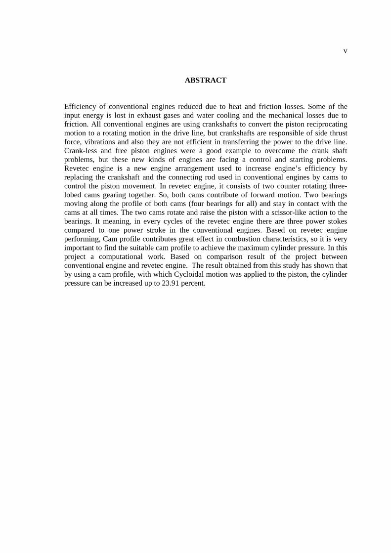
ABSTRACT
Efficiency of conventional engines reduced due to heat and friction losses. Some of the input energy is lost in exhaust gases and water cooling and the mechanical losses due to friction. All conventional engines are using crankshafts to convert the piston reciprocating motion to a rotating motion in the drive line, but crankshafts are responsible of side thrust force, vibrations and also they are not efficient in transferring the power to the drive line. Crank-less and free piston engines were a good example to overcome the crank shaft problems, but these new kinds of engines are facing a control and starting problems. Revetec engine is a new engine arrangement used to increase engine’s efficiency by replacing the crankshaft and the connecting rod used in conventional engines by cams to control the piston movement. In revetec engine, it consists of two counter rotating three-lobed cams gearing together. So, both cams contribute of forward motion. Two bearings moving along the profile of both cams (four bearings for all) and stay in contact with the cams at all times. The two cams rotate and raise the piston with a scissor-like action to the bearings. It meaning, in every cycles of the revetec engine there are three power stokes compared to one power stroke in the conventional engines. Based on revetec engine performing, Cam profile contributes great effect in combustion characteristics, so it is very important to find the suitable cam profile to achieve the maximum cylinder pressure. In this project a computational work. Based on comparison result of the project between conventional engine and revetec engine. The result obtained from this study has shown that by using a cam profile, with which Cycloidal motion was applied to the piston, the cylinder pressure can be increased up to 23.91 percent.
vi
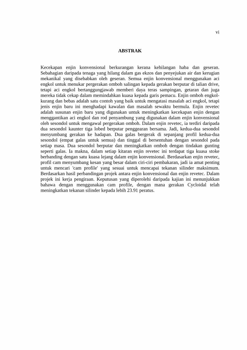
ABSTRAK
Kecekapan enjin konvensional berkurangan kerana kehilangan haba dan geseran. Sebahagian daripada tenaga yang hilang dalam gas ekzos dan penyejukan air dan kerugian mekanikal yang disebabkan oleh geseran. Semua enjin konvensional menggunakan aci engkol untuk menukar pergerakan omboh salingan kepada gerakan berputar di talian drive, tetapi aci engkol bertanggungjawab memberi daya teras sampingan, getaran dan juga mereka tidak cekap dalam memindahkan kuasa kepada garis pemacu. Enjin omboh engkol-kurang dan bebas adalah satu contoh yang baik untuk mengatasi masalah aci engkol, tetapi jenis enjin baru ini menghadapi kawalan dan masalah sewaktu bermula. Enjin revetec adalah susunan enjin baru yang digunakan untuk meningkatkan kecekapan enjin dengan menggantikan aci engkol dan rod penyambung yang digunakan dalam enjin konvensional oleh sesondol untuk mengawal pergerakan omboh. Dalam enjin revetec, ia terdiri daripada dua sesondol kaunter tiga lobed berputar penggearan bersama. Jadi, kedua-dua sesondol menyumbang gerakan ke hadapan. Dua galas bergerak di sepanjang profil kedua-dua sesondol (empat galas untuk semua) dan tinggal di bersentuhan dengan sesondol pada setiap masa. Dua sesondol berputar dan meningkatkan omboh dengan tindakan gunting seperti galas. Ia makna, dalam setiap kitaran enjin revetec ini terdapat tiga kuasa stoke berbanding dengan satu kuasa lejang dalam enjin konvensional. Berdasarkan enjin revetec, profil cam menyumbang kesan yang besar dalam ciri-ciri pembakaran, jadi ia amat penting untuk mencari 'cam profile' yang sesuai untuk mencapai tekanan silinder maksimum. Berdasarkan hasil perbandingan projek antara enjin konvensional dan enjin revetec. Dalam projek ini kerja pengiraan. Keputusan yang diperolehi daripada kajian ini menunjukkan bahawa dengan menggunakan cam profile, dengan mana gerakan Cycloidal telah meningkatkan tekanan silinder kepada lebih 23.91 peratus.
vii
TABLE OF CONTENTS
Page
SUPERVISOR’S DECLARATION ii
STUDENT’S DECLARATION iii
ACKNOWLEDGEMENTS iv
ABSTRACT v
ABSTRAK vi
TABLE OF CONTENTS vii
LIST OF TABLES x
LIST OF FIGURES xi
LIST OF SYMBOLS xiii
LIST OF ABBREVIATIONS xiv
CHAPTER 1 INTRODUCTION 1.1 BACKGROUND 1
1.2 PROBLEM STATEMENT 1
1.3 OBJECTIVE 2
1.4 SCOPE 2
1.5 FLOW CHART 3
1.6 GANTT CHART 4
CHAPTER 2 LITERATURE REVIEW
2.1 INTRODUCTION 5
2.2 REVETEC ENGINE 6
2.3 REVETEC ENGINE MODELLING 7
2.3.1 Revetec Engine Modelling For Two Stroke 2.3.2 Type of Revetec Engine
7 10
2.3.3 Advantage and Disadvantage 12
viii
2.4 TYPE OF CAM 13
2.4.1 Definition of cam 13 2.4.2 Classification of Cam Mechanisms 14 2.4.2.1 Modes of Input/ Output Motion 14 2.4.2.2 Follower Configuration 14 2.4.2.3 Follower Arrangement 16 2.4.2.4 Cam Shape 16 2.4.2.5 Constraints on the Follower 17 2.4.2.6 Examples in Sim Design 18 2.4.3 Cam Nomenclature 19
2.5 DERIVATION 20
2.3.1 Cycloidal Motion Calculation 20 2.3.2 Cylinder Pressure Calculation 22 2.3.3 Derivation of The Equation for conventional engine 22
2.6 SUMMARY 24
CHAPTER 3 METHODOLOGY
3.1 INTRODUCTION 25
3.2 DESCRIPTION OF PROJECT 26
3.3 FLOW CHART OF MATLAB PROGRAMMING 27
3.4 PROCEDURE IN DOING SIMULATION USING MATLAB
PROGRAMMING
28
3.4.1 Derivation of Cycloidal Motion Calculation for revetec engine 28 3.4.2 Derivation of the Equation for conventional engine 29 3.4.3 Derivation of Cylinder Pressure Calculation 30
3.5 SUMMARY 31
CHAPTER 4 RESULTS AND DISCUSSIONS
4.1 INTRODUCTION 32
4.2 RESULTS 32
4.2.1 Pressure for conventional engine 32 4.2.2 Pressure for revetec engine 35 4.2.3 Comparison Pressure between conventional engine and revetec
engine
37
ix
CHAPTER 5 CONCLUSION AND RECOMMENDATIONS
5.1 CONCLUSIONS 42
5.2 RECOMMENDATIONS FOR THE FUTURE RESEARCH 43
REFERENCES 44
APPENDICES 45
MATLAB Program Coding For Conventional Engine 45
MATLAB Function Coding For Conventional Engine 46
Graph For Conventional Engine 47
MATLAB Program Coding for Revetec Engine 48
MATLAB Function Coding for Revetec Engine 49
Graph For Revetec Engine 50
Characteristics Of Basic Curve
Graph Of Some Cam Curve
51
52
x
LIST OF TABLES
Table No. Title Page
4.1 Table conventional engine pressure during compression and
power stroke
32
4.2 Table of revetec engine pressure during compression and power
stroke 35
4.3 Comparison table between conventional engine and revetec
engine pressure during compression and power stroke 37
xi
LIST OF FIGURES
Figure No. Title Page
1.1 Flow chart of final year project 3
1.2 Gantt chart of final year project 4
2.1 Shaft cross-sectional view of a two-stroke engine comprising a single cylinder module with the cross-section being along the axis of the cylinders and transverse with respect to the engine
7
2.2 Cross-sectional view of another two-stroke engine comprising a
single cylinder module with the cross-section being in the plane of the central shaft of the engine
8
2.3 View of portion of an engine showing a piston in contact with
counter rotating trilobate cams 9
2.4 Revetec engine for X-Series 10
2.5 Revetec engine for Boxer- Series 10
2.6 Revetec engine for 120DegV- Series 11
2.7 Revetec engine for 60DegV- Series 11
2.8 Revetec engine for Inline- Series 12
2.9 Classification of cam mechanisms 15
2.10 Translating cam - translating follower 15
2.11 Grooved cam 16
2.12 Cylindrical cam and end cam 17
2.13 Constant diameter cam 17
2.14 Dual cam 18
2.15 SimDesign translating cam 18
2.16 SimDesign oscillating cam 19
xii
2.17
2.18
Cam nomenclature Figure of crankshaft and cam shaft
19
24
3.1 Flow Chart Of Matlab Programming 27
4.1 Graph conventional engine pressure during compression and power stroke
34
4.2 Graph of revetec engine pressure during compression and power
stroke 36
4.3 Comparison graph between conventional engine and revetec
engine pressure during compression and power stroke 39
xiii
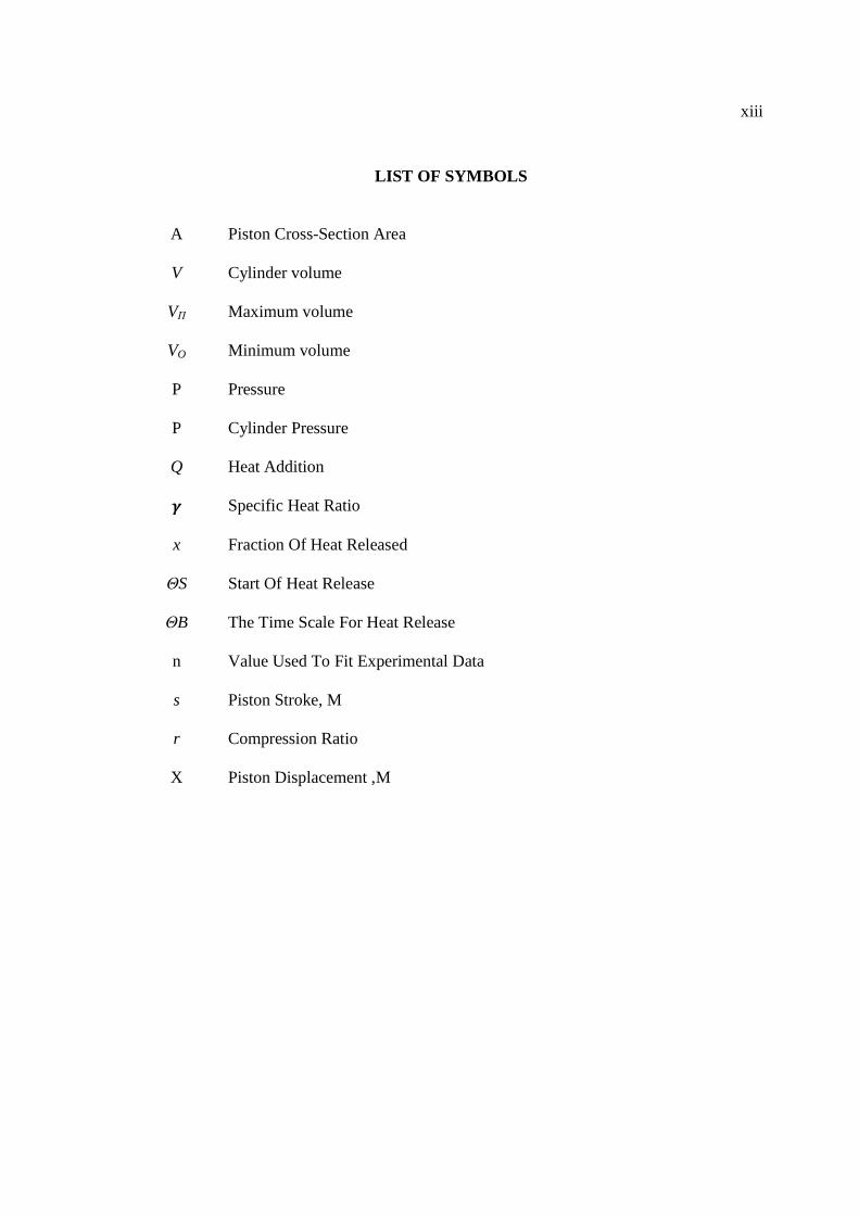
LIST OF SYMBOLS
A Piston Cross-Section Area
V Cylinder volume
VΠ Maximum volume
VO Minimum volume P Pressure P Cylinder Pressure
Q Heat Addition � Specific Heat Ratio x Fraction Of Heat Released ΘS Start Of Heat Release
ΘB The Time Scale For Heat Release
n Value Used To Fit Experimental Data s Piston Stroke, M r Compression Ratio
X Piston Displacement ,M
xiv
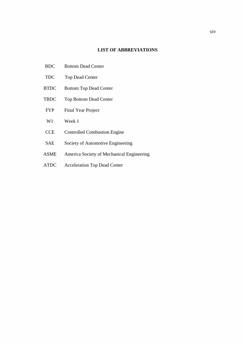
LIST OF ABBREVIATIONS
BDC Bottom Dead Center
TDC Top Dead Center
BTDC Bottom Top Dead Center
TBDC Top Bottom Dead Center
FYP Final Year Project
W1 Week 1
CCE Controlled Combustion Engine
SAE Society of Automotive Engineering
ASME America Society of Mechanical Engineering
ATDC Acceleration Top Dead Center
1
CHAPTER 1
INTRODUCTION
1.1 BACKGROUND
Revetec engine is a new engine arrangement, were cams are used instead of
crankshaft to convert the reciprocating piston motion to rotating motion. Crankshafts are
inefficient devices for efficiently transferring power from the pistons to the driveline,
with losses that can approach 36%. At the top of the piston stroke, where gas pressure is
highest, force transfer efficiency is at its lowest, though it rises as the piston descends.
Peak efficiency happens about 40% through the piston stroke, and then drops at an
exponential.
In addition, the piston does not travel a path that is strictly parallel to the bore, so
an angular force equal to the pressure on the top of the piston is transferred to the
cylinder wall. This increases friction, wear, and fuel consumption. So, revetec engine is
solution for this problem. By replacing the crankshaft and the connecting rod that used
in conventional engines, the engine efficiency will increase by controlled combustion
engine of the piston movement.
1.2 PROBLEM STATEMENT
Crankshafts are the main cause for many problems in the internal combustion
engine, like vibration, noise and cylinder wear. These poor efficiencies of the
crankshafts have leaded the engineers to invent other alternative to replace the
crankshafts functions (Mikalsen, 2007). When using cams instead of crankshafts, the
cam profile makes a great effect in combustion characteristics, so it is very important to
2
find the suitable cam profile to achieve the maximum cylinder pressure. In this project,
a comparison for one type of cam profiles, which gives a specific motion for the piston,
mainly Cycloidal motion, to calculate the cylinder pressure during compression and
combustion strokes. In this project an investigation of cam with cycloidal motion profile
will be done to find the effect of the cam profile on the cylinder pressure. Revetec
engine is a new custom engine.
1.3 OBJECTIVE
To investigate the effect of cam profile on the cylinder pressure
1.4 SCOPES
In this final year project there are three main point for the scope.
i. Modelling the cam profile using MATLAB.
ii. Simulating of cylinder pressure during the compression and exhaust strokes.
iii. Comparing these results with conventional engines.
3
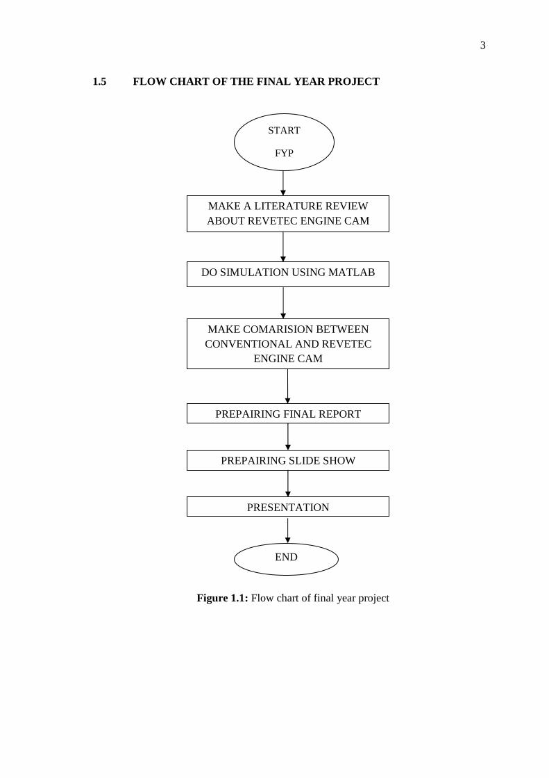
1.5 FLOW CHART OF THE FINAL YEAR PROJECT
Figure 1.1: Flow chart of final year project
START
FYP
MAKE A LITERATURE REVIEW ABOUT REVETEC ENGINE CAM
MAKE COMARISION BETWEEN CONVENTIONAL AND REVETEC
ENGINE CAM
PREPAIRING FINAL REPORT
PREPAIRING SLIDE SHOW
PRESENTATION
END
DO SIMULATION USING MATLAB
4
5
CHAPTER 2
LITERATURE REVIEW
2.1 INTRODUCTION
Currently, majority of the vehicle on the road used conventional engine. Revetec
engine technology is still new in the automotive industry. Many people do not know the
advantages of using revetec engine, when compared with conventional engines. It
occurs due to lack of information on revetec engine. Therefore, research on revetec
engine must be published to be seen by the public. So, people are more interested in
studying or using technology of revetec engine.
With this study, the rate of wastage of fuel consumption can be reduced. This is
because the revetec engine efficiency is better when compared with conventional
engines. The main problem in the internal combustion engine to a conventional engine
is the crankshaft. When the engine is running, a problem that often occurs like vibration,
friction wears of the cylinder, and noise. Lack of efficiency of the engine requires the
engineer to cope with a redesigned internal engine parts that can overcome the problem.
In 1996, Bradley Howell Smith, an Australian engineer conducting research and
in 2006 he created a new display engine called Controlled Combustion Engine (CCE).
This engine mechanism convert the reciprocating motion of the internal combustion
engines pistons, to rotating motion in the drive line, by using two counter three-lobed
cam geared together, two bearing run along the profile of both cam and stay in contact
with the cam at all times known as Revetec engine (Bradley, 2006).
6
Revetec engine is a new engine design. Revetec engine, replace the crankshaft
with the camshaft. In revetec engine, it consists of two counter rotating three-lobed
cams gearing together. So, both cams contribute of forward motion. Two bearings
moving along the profile of both cams (four bearings for all) and stay in contact with the
cams at all times. The two cams rotate and raise the piston with a scissor-like action to
the bearings.
It meaning, in every cycles of the revetec engine there are three power stokes
compared to one power stroke in the conventional engines. In each stroke of the engine
revetec, only 120 degrees cam rotates to complete a stroke, while the 360 degrees cam
rotates required to complete a stroke by a conventional engine. That is why, cam profile
contributes a major impact on engine performance and controlling the movement of the
piston.
2.2 REVETEC ENGINE
The Revetec Engine design consists of two counter-rotating three lobed cams
geared together, so both cams contribute to forward motion. Two bearings run along the
profile of both cams with four bearings in all and stay in contact with the cams at all
times. The bearings are mounted on the underside of the two inter-connected pistons,
which maintain the desired bearing to three lobed clearances throughout the stroke.
The two cams rotate and raise the piston with a scissor-like action to the bearings.
Once at the top of the stroke the air/fuel mixture is fired. The expanded gas then
forces the bearings down the ramps of the cams spreading them apart ending the stroke.
The effective cranking distance is determined by the length from the point of bearing
contact to the centre of the output shaft. A conventional engine's turning distance is half
of the piston stroke. The piston acceleration throughout the stroke is controlled by the
cam grind which can be altered to suit a wide variety of fuels, torque requirements and
rev range. The counter rotation is performed by a reverse gear set at a 1:3 ratio shaft
providing two stroke piston to 360 degrees of output shaft rotation.
7
2.3 REVETEC ENGINE MODELLING
2.3.1 Revetec engine modelling for two stroke
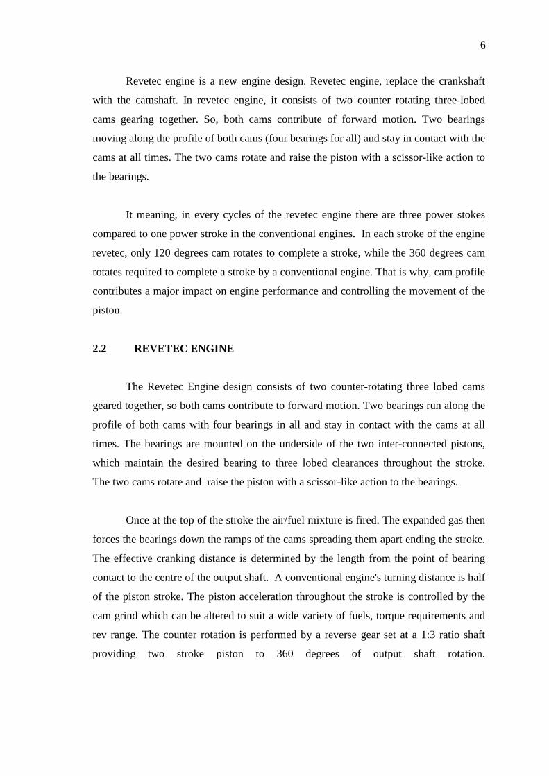
With reference to Figure 2.1, there is shown two-stroke engine 1 comprising a
single cylinder module having a single pair of cylinders made up of cylinders. Roller
bearings are carried by shaft, which correspond to the roller bearings as generally
indicated of figure 2.1
.
Figure 2.1: Cross-sectional view of a two-stroke engine comprising a single cylinder
module with the cross-section being along the axis of the cylinders and
transverse with respect to the engine shaft.
Source: Bradley (2006)
1- Comprising a single cylinder module, 2 and 3- cylinders. 4 and 5- pistons, 6a 6b-
fours rod, 7- central shaft, 8 and 9- trilobate cams, 10 and 11- roller bearings, 12- water
jacket, 13 and 14- spark plugs, 15- oil sump, 16- oil pump pickup, 17 and 18- balance
shafts, 19 and 20- inlet ports of exhaust ports.
8
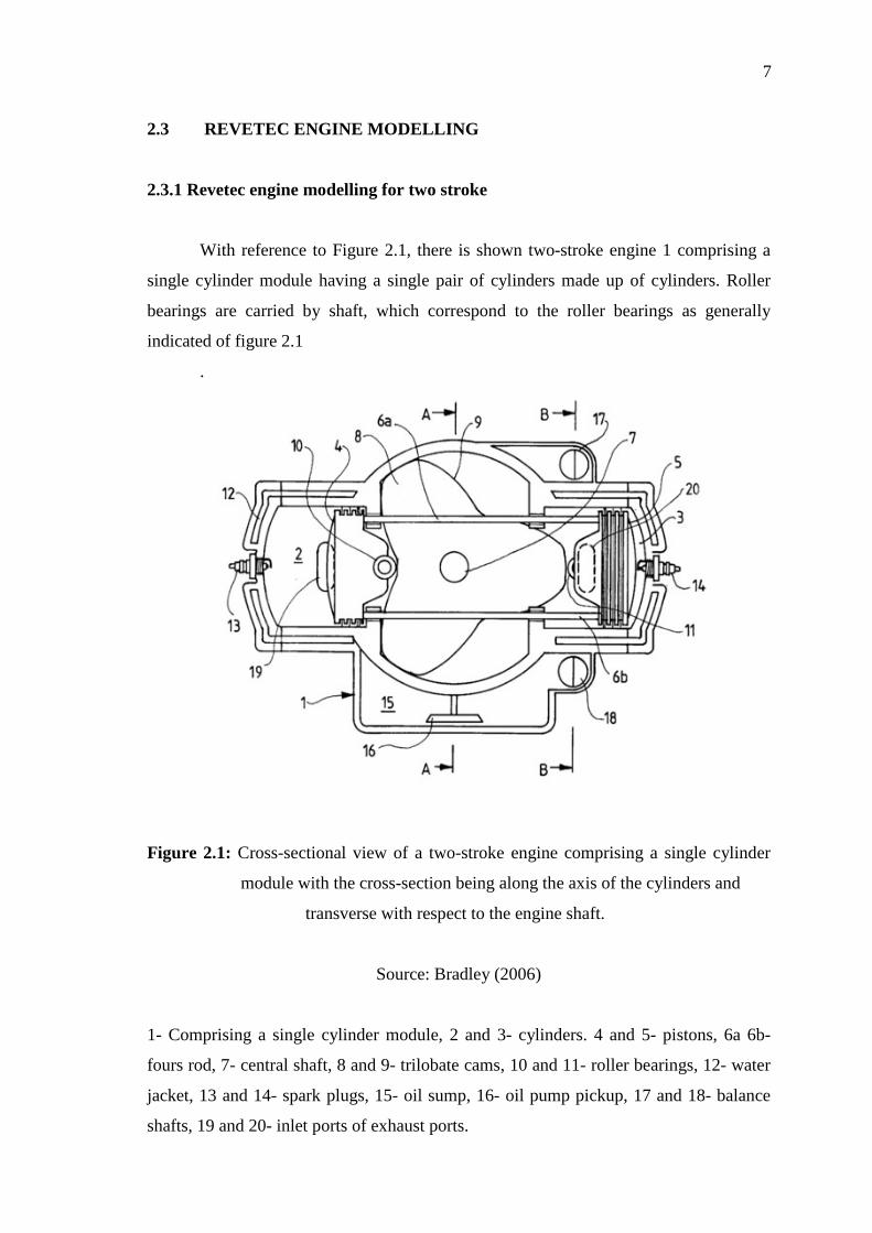
Turning to Figure 2.2, there is shown another two stroke engine having a single
cylinder module. The engine is shown in partial cross-section. In effect, half of the
engine block has been removed to reveal internal detail of the engine. The cross-section
is in a plane coincident with the axis of the central shaft of the engine. The engine block
has thus been split at its midline.
Figure 2.2: Cross-sectional view of another two-stroke engine comprising a single
cylinder module with the cross-section being in the plane of the central
shaft of the engine.
Source: Bradley (2006)
52- engine, 53- comprises block, 54 and 55- cylinder heads, 56 and 57- cylinders, 58-
shaft, 59- roller bearings, 60- a first trilobate cam fixed, 61- counter rotating trilobate
cam, 62- piston in cylinder 56, 63- piston in cylinder 57, 64 and 65- four connecting
rods, 66- piston a bearing boss, 67- holds shaft, 68 and 69- roller bearings, 70- bearing
boss, 71- gear train, 72- housing, 73- sun gear, 74 and 75- drive gears, 76 and 77-
planetary gears, 78 and 79- shafts, 80 and 81- second set of planetary gears, 82- sun
gear, 83-sleeve, 84 and 85- shafts.
9
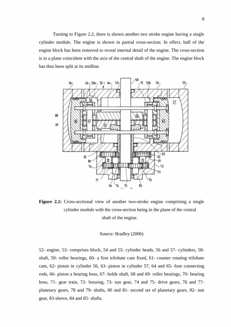
An engine with offset cam contacting bearings is shown schematically in Figure
2.3. In this figure, which is a view along the central shaft of an engine, cam , counter
rotating cam , and piston are shown. Piston includes bearing bosses and which carry
roller bearings and, which bearings are shown in contact with a lobe, respectively, of the
trilobate cams.
Figure 2.3: View of portion of an engine showing a piston in contact with counter
rotating trilobate cams.
Source: Bradley (2006)
86- cam, 87- counter rotating cam, 88- piston, 89 and 90- bearing bosses, 91 and 92-
roller bearings, 93 and 94- which bearings are shown in contact with a lobe, 95 and 96-
axes
10
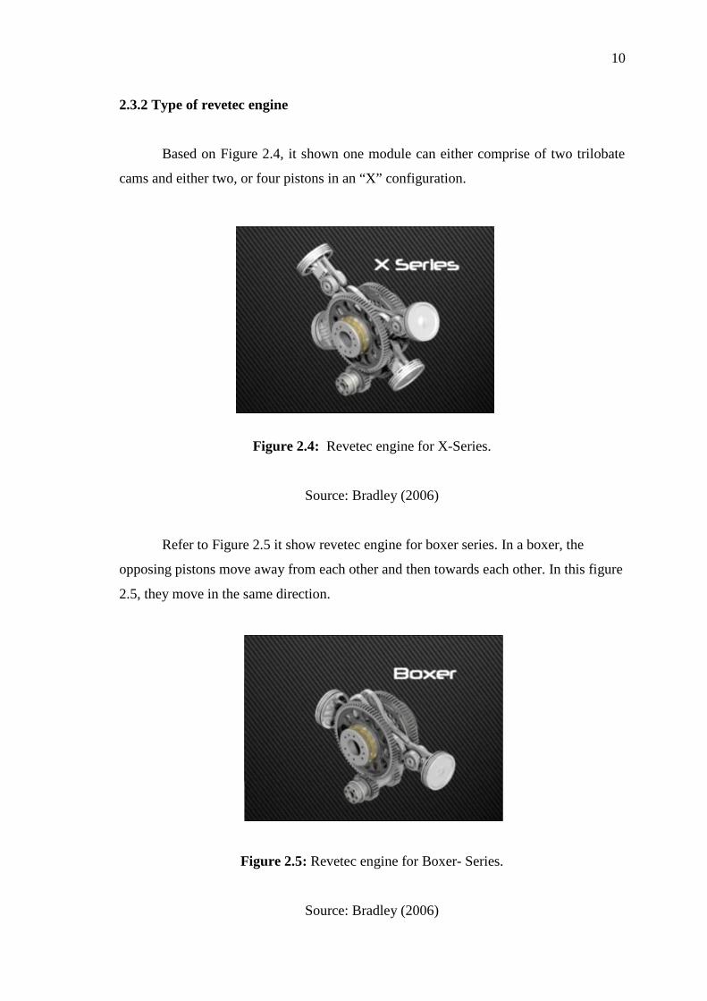
2.3.2 Type of revetec engine
Based on Figure 2.4, it shown one module can either comprise of two trilobate
cams and either two, or four pistons in an “X” configuration.
Figure 2.4: Revetec engine for X-Series.
Source: Bradley (2006)
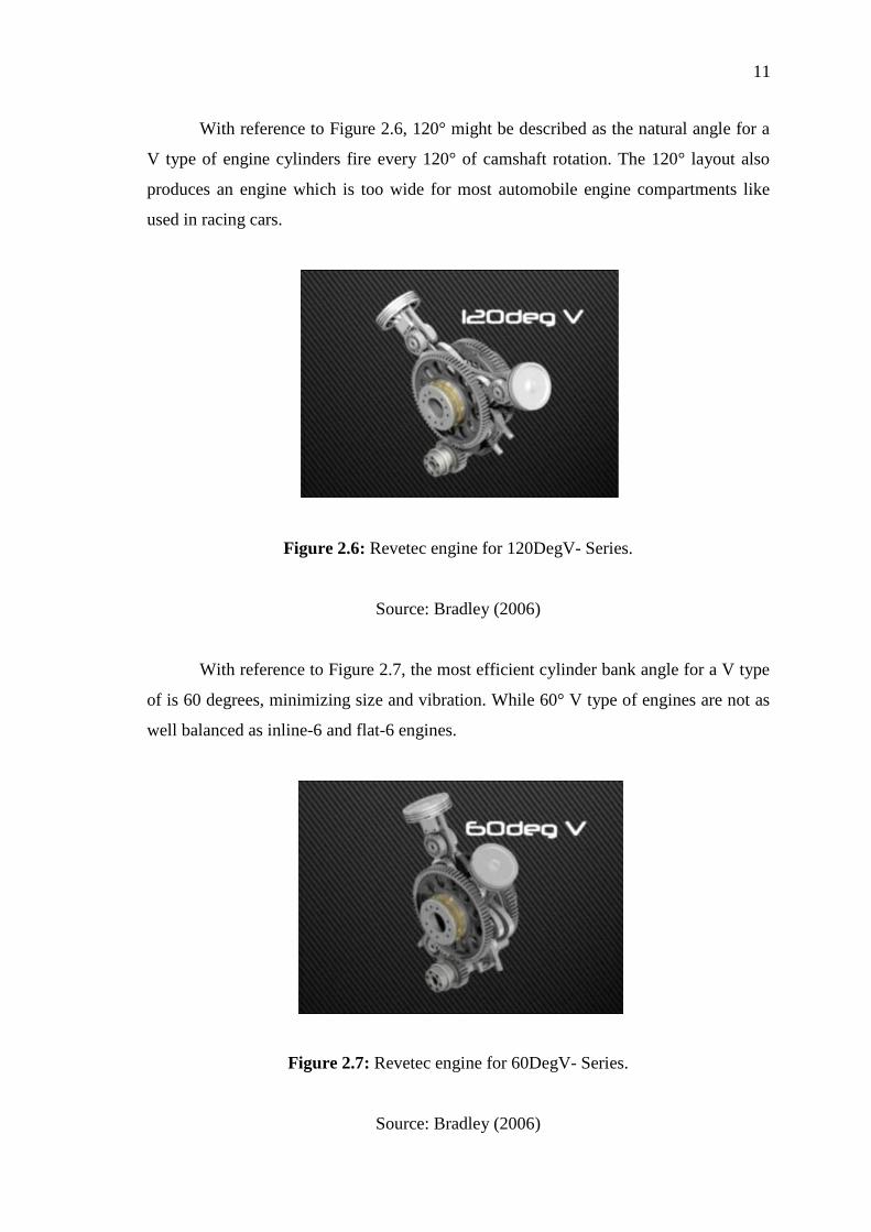
Refer to Figure 2.5 it show revetec engine for boxer series. In a boxer, the
opposing pistons move away from each other and then towards each other. In this figure
2.5, they move in the same direction.
Figure 2.5: Revetec engine for Boxer- Series.
Source: Bradley (2006)
11
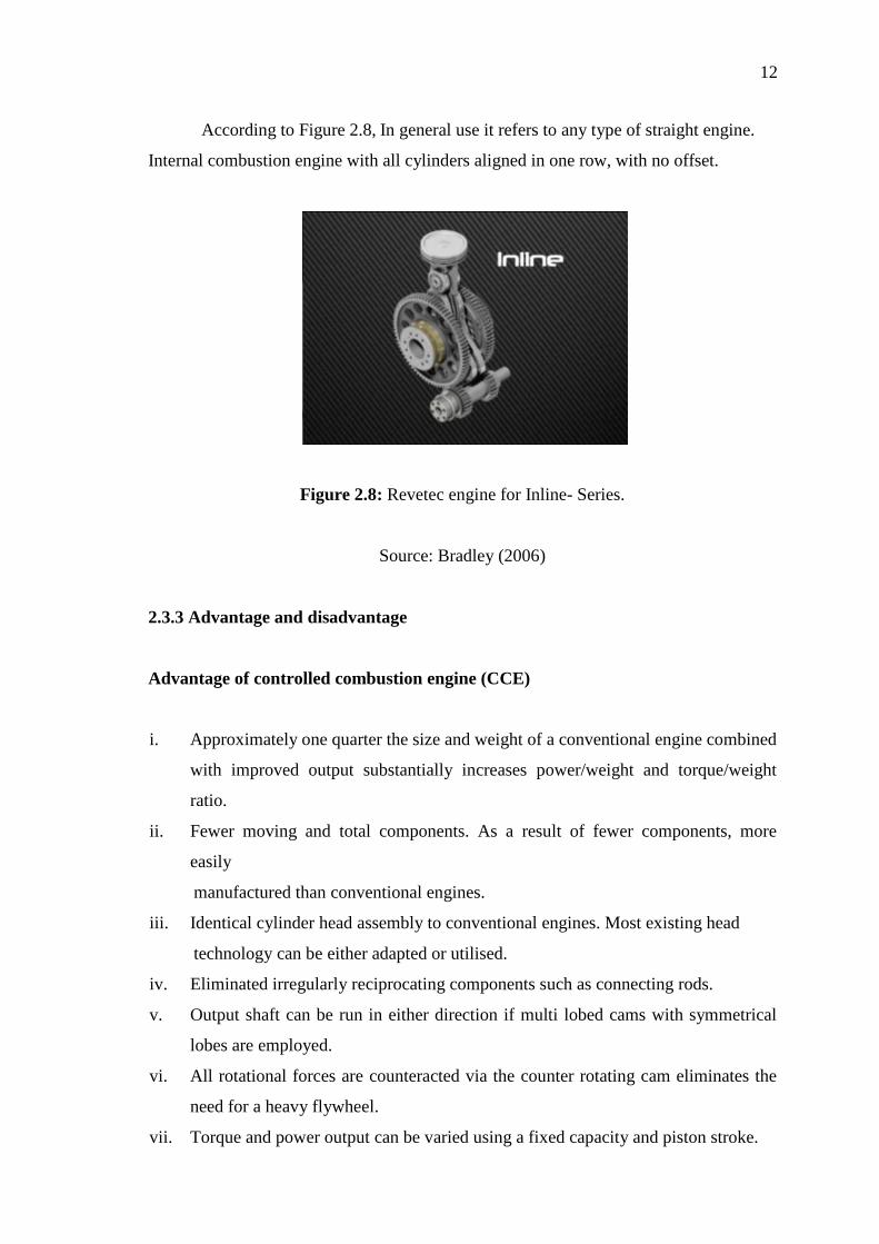
With reference to Figure 2.6, 120° might be described as the natural angle for a
V type of engine cylinders fire every 120° of camshaft rotation. The 120° layout also
produces an engine which is too wide for most automobile engine compartments like
used in racing cars.
Figure 2.6: Revetec engine for 120DegV- Series.
Source: Bradley (2006)
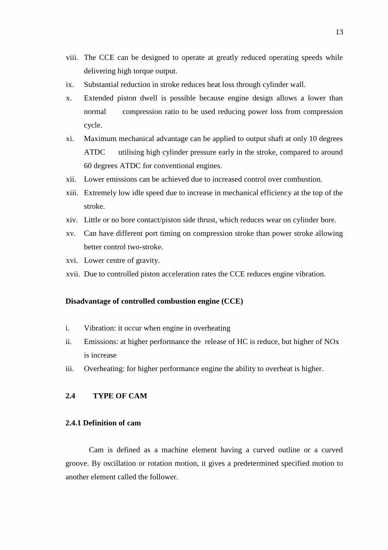
With reference to Figure 2.7, the most efficient cylinder bank angle for a V type
of is 60 degrees, minimizing size and vibration. While 60° V type of engines are not as
well balanced as inline-6 and flat-6 engines.
Figure 2.7: Revetec engine for 60DegV- Series.
Source: Bradley (2006)
12
According to Figure 2.8, In general use it refers to any type of straight engine.
Internal combustion engine with all cylinders aligned in one row, with no offset.
Figure 2.8: Revetec engine for Inline- Series.
Source: Bradley (2006)
2.3.3 Advantage and disadvantage
Advantage of controlled combustion engine (CCE)
i. Approximately one quarter the size and weight of a conventional engine combined
with improved output substantially increases power/weight and torque/weight
ratio.
ii. Fewer moving and total components. As a result of fewer components, more
easily
manufactured than conventional engines.
iii. Identical cylinder head assembly to conventional engines. Most existing head
technology can be either adapted or utilised.
iv. Eliminated irregularly reciprocating components such as connecting rods.
v. Output shaft can be run in either direction if multi lobed cams with symmetrical
lobes are employed.
vi. All rotational forces are counteracted via the counter rotating cam eliminates the
need for a heavy flywheel.
vii. Torque and power output can be varied using a fixed capacity and piston stroke.
13
viii. The CCE can be designed to operate at greatly reduced operating speeds while
delivering high torque output.
ix. Substantial reduction in stroke reduces heat loss through cylinder wall.
x. Extended piston dwell is possible because engine design allows a lower than
normal compression ratio to be used reducing power loss from compression
cycle.
xi. Maximum mechanical advantage can be applied to output shaft at only 10 degrees
ATDC utilising high cylinder pressure early in the stroke, compared to around
60 degrees ATDC for conventional engines.
xii. Lower emissions can be achieved due to increased control over combustion.
xiii. Extremely low idle speed due to increase in mechanical efficiency at the top of the
stroke.
xiv. Little or no bore contact/piston side thrust, which reduces wear on cylinder bore.
xv. Can have different port timing on compression stroke than power stroke allowing
better control two-stroke.
xvi. Lower centre of gravity.
xvii. Due to controlled piston acceleration rates the CCE reduces engine vibration.
Disadvantage of controlled combustion engine (CCE)
i. Vibration: it occur when engine in overheating
ii. Emissions: at higher performance the release of HC is reduce, but higher of NOx
is increase
iii. Overheating: for higher performance engine the ability to overheat is higher.
2.4 TYPE OF CAM
2.4.1 Definition of cam
Cam is defined as a machine element having a curved outline or a curved
groove. By oscillation or rotation motion, it gives a predetermined specified motion to
another element called the follower.