Embed Size (px)
Citation preview
Design of Semi-Autonomous Robots for
Competitive Robotics
P. Benavidez, C. Gleinser, A. Jaimes, J. Labrado, C. Riojas and Mo Jamshidi, Ph.D., Lutcher Brown Endowed
Chair
Department of Electrical and Computer Engineering
The University of Texas at San Antonio
San Antonio, USA
[email protected], [email protected], [email protected], [email protected], [email protected],
Abstract—This paper presents the first-generation
design of two classes of semi-autonomous competitive
robots created in-house at University of Texas at San
Antonio for iTEC, the educational outreach program
sponsored at the university. The robots created for the
outreach program will compete with each other in
games of sumo-wrestling and soccer. Design of the
robots involved the choice on the physical configuration
of the robot systems, electronics systems, sensor suites,
semi-autonomous behaviors, human control overrides
and computer programming methodologies utilized.
This paper will go over highlights of each system and
remarks over the design process.
Keywords-mobile robot; competitive robots; computer
vision; sumo; soccer
I. INTRODUCTION
Competitive robotics competitions have been around for many years to motivate people towards education and careers in science, technology, engineering, and math (STEM). In addition, this has sparked competitions at the university level to enhance the effectiveness of learned material. Two popular types of competitions are for sumo-wrestling and soccer playing robots. These competitions have led to advanced robot designs with navigation algorithms utilizing some combinations of image processing, artificial intelligence, crisp logic, fuzzy logic, and various sensors to allow robots to play a game autonomously. In the game of sumo-wrestling, the goal is for a robot to push its opponent out of a circular-shaped arena. The goal of a team of soccer-playing robots is to score the highest number of points in a given time limit with the basic rules of soccer.
Our goal was to design, produce and deliver four robots each of both types of robots to the STEM outreach program at the university. We were tasked with taking some already-purchased commercial-off-the-shelf (COTS) products (such as the chassis, motor drivers, microcontrollers, etc.) and completing the robot electrical and mechanical designs. This required planning electrical circuitry given a collection of motor drivers and sensors to use, purchasing of additional
electrical components, planning of mechanical components, machining the components, construction, software development, and testing of the robots.
In terms of the mechanical design we reviewed many published designs for soccer-playing robots. The necessary physical components for soccer-playing robots were the kicking mechanism (for shooting the ball), a dribbling mechanism (for travelling with the ball), locomotion, and a camera for determining the ball position. We found many designs from RoboCup, a major soccer robot competition, that used similar components and designs. For a kicking mechanism, solenoid-actuated bumpers were used in [1], dual solenoid-actuated bumpers were used in [2], and a spring mechanism was used in [3]. Designers of the kicking mechanisms stated their solenoid-actuated kickers took many design iterations to get the optimal output and their required size; however, they also stated that the performance of the resulting kicking mechanism was worth the time spent on design. Designs for dribbling mechanisms are usually a counter-rotating cylindrical bar as in [3] and [4]. Given some initial tests, the cost of machining time and the cited number of robot iterations that it took other schools to get the designs just right, we opted for a simpler approach to the kicking and dribbling mechanisms, similar to that of the mechanism used in foosball. For the sumo-playing robots, the only real critical requirement of such a robot was to deny the opponent traction. Denial of traction is typically obtained by lifting the tires (or treads) of an opponent to reduce the torque necessary to push it out of the ring. In [5], the classic front-oriented plow with a relatively low profile is used by a robot to get under its opponent to take the advantage. We decided on what we believe through our research is unique to sumo-bots, and that is to allow a robot to lift its opponent using an actuated plow. In terms of electrical components and microcontrollers, there were many options available. We decided on the less expensive option of using Arduino microcontrollers [6] and several other COTS products for motor control, power supplies, cameras, and actuators. The rest of the paper is organized as follows: detail into the design of the physical configuration and mechanical systems on each robot, the communication protocol used, and semi-autonomous actions implemented by the robots.
II. PHYSICAL CONFIGURATION AND MECHANICAL
SYSTEMS
A. Sumo Robots
Major design components of the sumo robots are the plow design, chassis and differential drive system. These are described in the following sections.
1) Plow Design: The implementation of the plow
design was chosen so that that one of the player could gain
a mechanical advantage over the other player. To maintain
a compact robust design it was important to design around
the materials and the mechanics of the moving design. The
materials chosen were Lexan™ and polyethylene plastic
for the components doing the lifting and taking the impact
of the opponent. The moving mechanisms, comprised of
aluminum and composite material, include the hinges
allowing axial motion and the actuation hinge allowing the
pushing motion. The linear actuator is comprised of
aluminum and plastic. Aluminum tubing was crafted to act
as the holding brace and the housing for the actuating
motor. The housing is also held in place by alloy steel bolts
and was also chosen for their ability to withstand high
stress. In addition to their durability these materials are
relatively easy to work with.
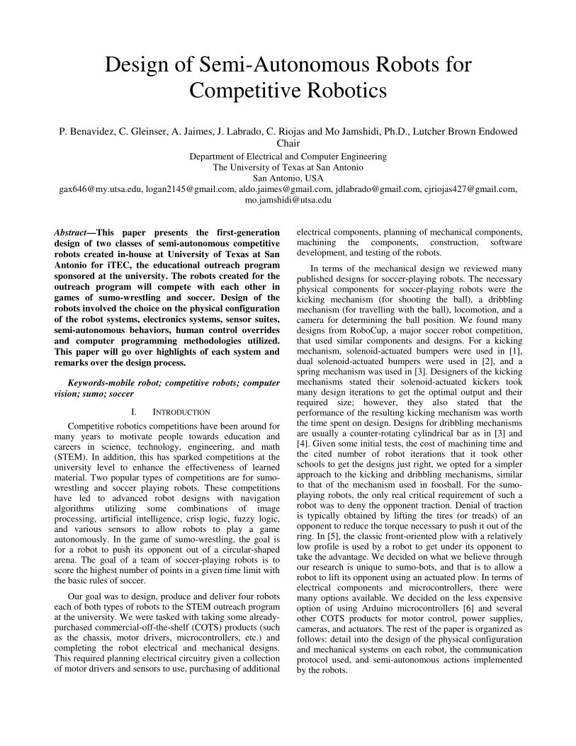
2) Chassis: The bodies of the sumo robots are made of
cut aluminum and Lexan™ plastic mounted to a
commercial-off-the-shelf (COTS) four-wheel drive base
chassis provided by Lynxmotion. Lexan™ and aluminum
materials were chosen for their durability and relative ease
to be machined. The cut materials form a box, which
mounts securely to the base chassis and provides an area
for the electronics to be mounted inside the robot. The
aluminum wall in the front of the robot allows for a
reinforced structure at the point of highest impact. A
thicker aluminum wall is used in the back of the robot to
act as a counter weight. The wall also acts as a measure to
dissipate heat from the power supply and ground the
chassis. Two of the finished robots are shown in Figure 1.
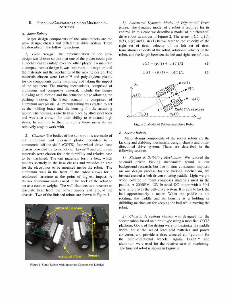
3) Linearized Dynamic Model of Differential Drive
Robot: The dynamic model of a robot is required for its
control. In this case we describe a model of a differential
drive robot as shown in Figure 2. The terms �ℓ���, �����,
����, ���� and L in (1) below refer to the velocity of the
right set of tires, velocity of the left set of tires,
translational velocity of the robot, rotational velocity of the
robot, and the length between the left and right sets of tires.
���� = ������ + �ℓ���� 2⁄ (1)
���� = ������ −�ℓ���� �⁄ (2)
B. Soccer Robots
Major design components of the soccer robots are the kicking and dribbling mechanism design, chassis and omni-directional drive system. These are described in the following sections.
1) Kicking & Dribbling Mechanism: We favored the
solenoid driven kicking mechanism found in our
background research, but due to time constraints imposed
on our design process for the kicking mechanism, we
instead created a belt-driven rotating paddle. Light-weight
wood covered in foam composes materials used in the
paddle. A 200RPM, 12V brushed DC motor with a 50:1
gear ratio drives the belt-drive system. It is able to kick the
ball approximately a meter. When the paddle is not
rotating, the paddle and its housing is a holding or
dribbling mechanism for keeping the ball while moving the
robot.
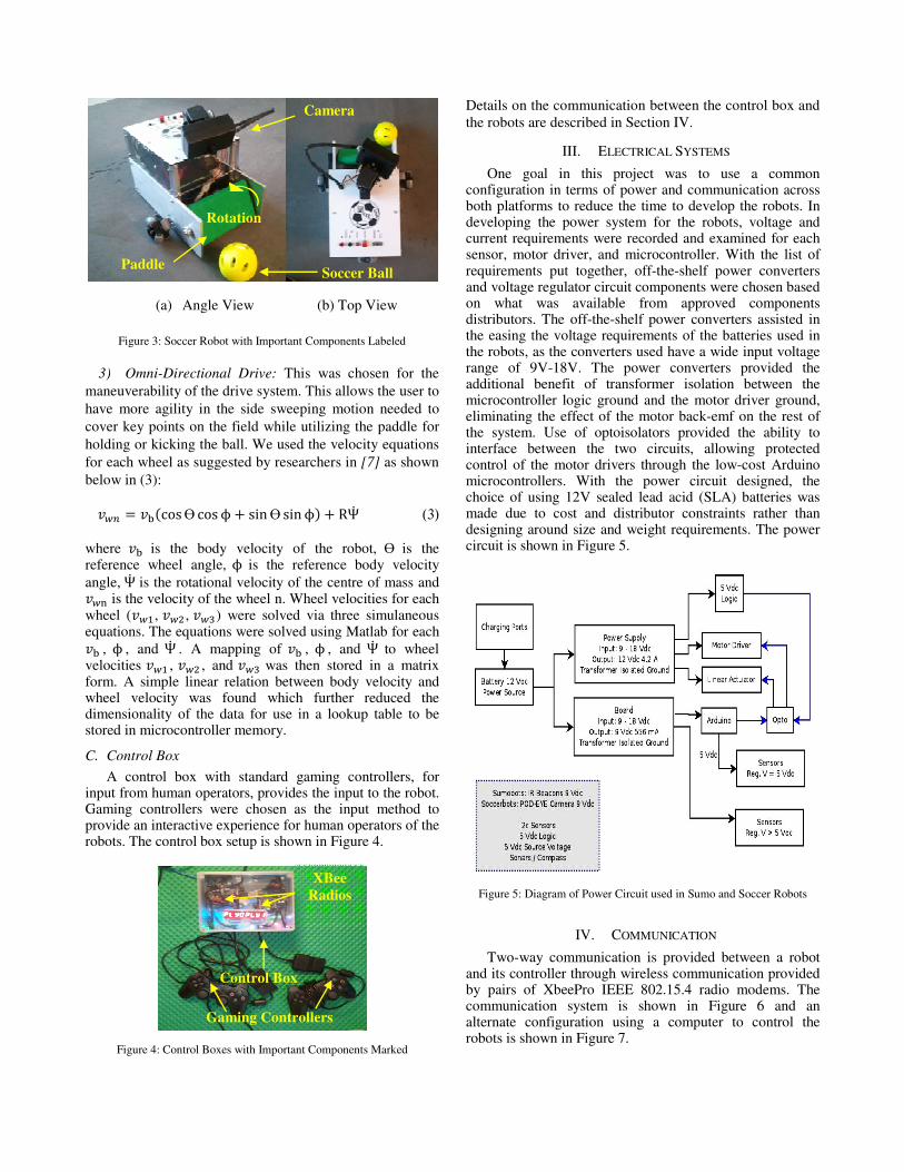
2) Chassis: A custom chassis was designed for the
soccer robots based on a prototype using a modified-COTS
platform. Goals of the design were to maximize the paddle
width, house the sealed lead acid batteries and power
converter, and provide a three-wheeled configuration for
the omni-directional wheels. Again, Lexan™ and
aluminum were used for the relative ease of machining.
The finished robot is shown in Figure 3.
Actuated Plow Sonars
Infrared Beacons
�����
�����
����
L Right Side of Robot
��
��
�����
��
�� �����
�����
Figure 2: Model of Differential Drive Robot
Figure 1: Sumo Robots with Important Components Labeled
3) Omni-Directional Drive: This was chosen for the
maneuverability of the drive system. This allows the user to
have more agility in the side sweeping motion needed to
cover key points on the field while utilizing the paddle for
holding or kicking the ball. We used the velocity equations
for each wheel as suggested by researchers in [7] as shown
below in (3):
��� = ���cosϴ cosϕ + sinϴ sinϕ� + RΨ (3)
where �� is the body velocity of the robot, ϴ is the reference wheel angle, ϕ is the reference body velocity
angle, Ψ is the rotational velocity of the centre of mass and ��! is the velocity of the wheel n. Wheel velocities for each wheel (��", ��# , ��$) were solved via three simulaneous equations. The equations were solved using Matlab for each
�� , ϕ , and Ψ . A mapping of �� , ϕ , and Ψ to wheel velocities ��" , ��# , and ��$ was then stored in a matrix form. A simple linear relation between body velocity and wheel velocity was found which further reduced the dimensionality of the data for use in a lookup table to be stored in microcontroller memory.
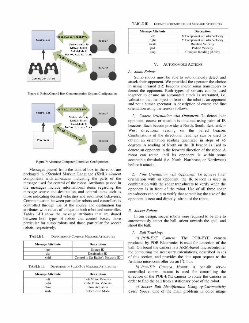
C. Control Box
A control box with standard gaming controllers, for input from human operators, provides the input to the robot. Gaming controllers were chosen as the input method to provide an interactive experience for human operators of the robots. The control box setup is shown in Figure 4.
Details on the communication between the control box and
the robots are described in Section IV.
III. ELECTRICAL SYSTEMS
One goal in this project was to use a common configuration in terms of power and communication across both platforms to reduce the time to develop the robots. In developing the power system for the robots, voltage and current requirements were recorded and examined for each sensor, motor driver, and microcontroller. With the list of requirements put together, off-the-shelf power converters and voltage regulator circuit components were chosen based on what was available from approved components distributors. The off-the-shelf power converters assisted in the easing the voltage requirements of the batteries used in the robots, as the converters used have a wide input voltage range of 9V-18V. The power converters provided the additional benefit of transformer isolation between the microcontroller logic ground and the motor driver ground, eliminating the effect of the motor back-emf on the rest of the system. Use of optoisolators provided the ability to interface between the two circuits, allowing protected control of the motor drivers through the low-cost Arduino microcontrollers. With the power circuit designed, the choice of using 12V sealed lead acid (SLA) batteries was made due to cost and distributor constraints rather than designing around size and weight requirements. The power circuit is shown in Figure 5.
IV. COMMUNICATION
Two-way communication is provided between a robot and its controller through wireless communication provided by pairs of XbeePro IEEE 802.15.4 radio modems. The communication system is shown in Figure 6 and an alternate configuration using a computer to control the robots is shown in Figure 7.
Gaming Controllers
Control Box
XBee
Radios
(a) Angle View (b) Top View
Paddle
Camera
Soccer Ball
Rotation
Figure 3: Soccer Robot with Important Components Labeled
Figure 5: Diagram of Power Circuit used in Sumo and Soccer Robots
Figure 4: Control Boxes with Important Components Marked
Messages passed from the control box to the robot are
packaged in eXtended Markup Language (XML) element components with attributes indicating the parts of the message used for control of the robot. Attributes passed in the messages include informational items regarding the message source and destination, and control items such as those indicating desired velocities and automated behaviors. Communication between particular robots and controllers is controlled through use of the source and destination tag attributes with values of unique to both robot and controller. Tables I-III show the message attributes that are shared between both types of robots and control boxes, those particular for sumo robots and those particular for soccer robots, respectively.
TABLE I. DEFINITION OF COMMON MESSAGE ATTRIBUTES
Message Attribute Description
src Source ID
dst Destination ID
xbid Control to Set Radio’s Network ID
TABLE II. DEFINITION OF SUMO BOT MESSAGE ATTRIBUTES
Message Attribute Description
left Left Motor Velocity
right Right Motor Velocity
plow Plow Actuation
rush Select Rush Mode
TABLE III. DEFINITION OF SOCCER BOT MESSAGE ATTRIBUTES
Message Attribute Description
left X Component of Polar Velocity
right Y Component of Polar Velocity
rotate Rotation Velocity
pad Paddle Velocity
cmp Compass Reading [0-359]
V. AUTONOMOUS ACTIONS
A. Sumo Robots
Sumo robots must be able to autonomously detect and attack their opponent. We provided the operator the choice in using infrared (IR) beacons and/or sonar transducers to detect the opponent. Both types of sensors can be used together to ensure an automated attack is warranted, i.e. validation that the object in front of the robot is an opponent and not a human spectator. A description of coarse and fine orientation using the sensors follows.
1) Coarse Orientation with Opponent: To detect their
opponent, coarse orientation is obtained using pairs of IR
beacons. Each beacon provides a North, South, East, and/or
West directional reading on the paired beacon.
Combinations of the directional readings can be used to
obtain an orientation reading quantized in steps of 45
degrees. A reading of North on the IR beacon is used to
denote an opponent in the forward direction of the robot. A
robot can rotate until its opponent is within some
acceptable threshold (i.e. North, Northeast, or Northwest)
before it attacks.
2) Fine Orientation with Opponent: To achieve finer
orientation with an opponent, the IR beacon is used in
combination with the sonar transducers to verify when the
opponent is in front of the robot. Use of all three sonar
transducers can help to verify that something the size of the
opponent is near and directly infront of the robot.
B. Soccer Robots
In our design, soccer robots were required to be able to autonomously detect the ball, orient towards the goal, and shoot the ball.
1) Ball Tracking:
a) POB-EYE Camera: The POB-EYE camera
produced by POB Electronics is used for detection of the
ball. On board the camera is a ARM-based microcontroller
for computing the necessary calculations, described in (c)
of this section, and provides the data upon request to the
Arduino microcontroller via an I2C bus.
b) Pan-Tilt Camera Mount: A pan-tilt servo-
controlled camera mount is used for controlling the
direction of the POB-EYE camera to rotate the camera in
order to find the ball from a stationary pose of the robot.
c) Soccer Ball Identification Using rg-Chromaticity
Color Space: One of the main problems in color image
Figure 6: Robot/Control Box Communication System Configuration
Figure 7: Alternate Computer Controlled Configuration
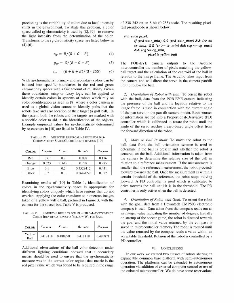
processing is the variablility of colors due to local intensity
shifts in the environment. To abate this problem, a color
space called rg-chromaticity is used by [8], [9] to remove
the light intensity from the determination of the color.
Transforms to the rg-chromaticity space are listed below in
(4)-(6).
%&� =' �' + ( + )�⁄ (4)
*&� = ( �' + ( + )�⁄ (5)
+&� = �' + ( + )� �3 ∗ 255�⁄ (6)
With rg-chromaticity, primary and secondary colors can be
isolated into specific boundaries in the red and green
chromaticity spaces with a fair amount of reliability. Given
these boundaries, crisp or fuzzy logic can be applied to
identify certain colors in systems of robots which rely on
color identification as seen in [8] where a color camera is
used as a global vision source to identify paths that the
robots take and also location of their target (a golf ball). In
the system, both the robots and the targets are marked with
a specific color to aid in the identification of the objects.
Example empirical values for rg-chromaticity determined
by researchers in [10] are listed in Table IV.
TABLE IV. SELECTED EMPIRCAL RESULTS FOR RG-CHROMATICITY SPACE COLOR IDENTIFICATION [10]
COLOR /0/,234 /0,256 70/,234 70/,256
Red 0.6 0.7 0.088 0.176
Orange 0.523 0.619 0.238 0.285
Blue 0.1 0.2 0.3529412 0.441
Black 0.2 0.3 0.2647059 0.352
Examining results of [10] in Table 1, identification of
colors in the rg-chromativity space is appropriate for
identifying colors uniquely which have regions that do not
overlap. Applying the color transform to numerous images
taken of a yellow wiffle ball, pictured in Figure 3, with the
camera for the soccer bot, Table V is produced.
TABLE V. EMPIRCAL RESULTS FOR RG-CHROMATICITY SPACE
COLOR IDENTIFICATION OF A YELLOW WIFFLE BALL
COLOR /0/,234 /0,256 70/,234 70/,256
Yellow
Ball 0.418118 0.488798 0.418118 0.483871
Additional observations of the ball color detection under
different lighting conditions showed that a secondary
metric should be used to ensure that the rg-chromaticity
measure was in the correct color region; that metric is the
red pixel value which was found to be required in the range
of 238-242 on an 8-bit (0-255) scale. The resulting pixel-
test pseudocode is shown below:
For each pixel:
if (red >= r_min) && (red <= r_max) && (cr <=
cr_max) && (cr >= cr_min) && (cg <= cg_max)
&& (cg >= cg_min)
pixel is yellow ball
The POB-EYE camera outputs to the Arduino
microcontroller the number of pixels matching the yellow-
ball target and the calculation of the centroid of the ball in
relation to the image frame. The Arduino takes input from
the camera and will direct the servo in the camera pan/tilt
unit to follow the ball.
2) Orientation of Robot with Ball: To orient the robot
with the ball, data from the POB-EYE camera indicating
the presence of the ball and its location relative to the
image frame is used in conjunction with the current angle
of the pan servo in the pan-tilt camera mount. Both sources
of information are fed into a Proportional-Derivative (PD)
controller which is calibrated to rotate the robot until the
angle of the servo reaches a zero-based angle offset from
the forward direction of the robot.
3) Move to Ball Position: To move the robot to the
ball, data from the ball orientation scheme is used to
determine if the ball is present and whether the robot is
centered on the ball. Additional information is taken from
the camera to determine the relative size of the ball in
relation to a reference measurement. If the measurement is
smaller than the reference measurement, the robot proceeds
forward towards the ball. Once the measurement is within a
certain threshold of the reference, the robot stops moving
forward. A PD controller is used which is calibrated to
drive towards the ball until it is in the threshold. The PD
controller is only active when the ball is detected.
4) Orientation of Robot with Goal: To orient the robot
with the goal, data from a Devantech CMPS03 electronic
compass is used. Data taken from the compass reads out as
an integer value indicating the number of degrees. Initially
on startup of the soccer game, the robot is directed towards
the goal and the initial value returned by the compass is
saved in microcontroller memory.The robot is rotated until
the value returned by the compass reads a value within an
acceptable threshold. Rotaion of the robot is controlled by a
PD controller.
VI. CONCLUSIONS
In our work we created two classes of robots sharing an expandable common base platform with semi-autonomous operation. The platforms can be extended to autonomous operation via addition of external computer control or use of the onboard microcontroller. We do have some reservations
about the design processes, materials and components that we used. We plan to address our concerns in order to improve future designs of robots created in our lab. In particular, we plan to design printed circuit boards in place of solder-on perforated protoboards to reduce the overall time spent on placing components and the amount of errors made in the process of producing several boards by hand. We learned quickly in initial prototypes the importance of electrical isolation between the microcontroller and motor drivers when using COTS products that have different electrical ratings. Talking specifically on the soccer bots, we feel that given more time to design a future robot, pan-tilt camera units could be replaced by omni-directional cameras (similar to other soccer-bot designs noted in our background research). Omni-directional cameras have no moving parts and are more efficient in terms of power since there would be no servos to rotate. Ball scanning and detection times would also be less without having to move a servo to redirect the camera view. On the sumo-bots, we like the plow design but would suggest to others to design around a medium-to-heavy duty linear actuator with a high static and dynamic load characteristic, rather than that of a light-duty actuator that comes in a smaller form factor. The reason for this suggestion is due to the vast difference in durability and quality that we encountered with the light-duty actuators versus the heavy duty ones.
REFERENCES
[1] Ruud Tilburgs. (2006, November) Design and
Realization of a Solenoid for a Robocup Kicking
Device. Document.
[2] Joel DeLuca, Amanda Li, Tamer Kalla, Matthew
Perttula, and James Wilkie. (2011, June) The
University of British Columbia - Thunderbots
Manipulator. [Online].
http://design.engineering.ubc.ca/files/gravity_forms/3
/2011/06/Thunderbot%20technical%20paper.pdf
[3] Kuo-Yang Tu and Shi-Chao Luo, "Design and
Implementation of Omni-Directional Soccer Robots
for RoboCup," in Systems, Man and Cybernetics,
2006. SMC '06. IEEE International Conference on ,
October, 2006, pp. 2000-2005.
[4] Misael Soto Ruiz and Alfredo Weitzenfeld, "Soccer
Dribbler Design for the Eagle Knights RoboCup
Small Size Robot," in Robotics Symposium, 2006.
LARS '06. IEEE 3rd Latin American, 2006, pp. 34-
40.
[5] John Palmisano. (2011, December) Society of Robots
- Sumo Robot Contruction - Stampy. [Online].
http://www.societyofrobots.com/robot_sumo.shtml
[6] Arduino. (2011, December) Arduino. [Online].
http://www.arduino.cc/
[7] Mark Ashmore and Nick Barnes, "Omni-drive robot
motion on curved paths: The fastest path between
two points is not a straight-line," in AI '02
Proceedings of the 15th Australian Joint Conference
on Artificial Intelligence: Advances in Artificial
Intelligence , Canberra, 2002, pp. 225-236.
[8] Guy K. Kloss, Heesang Shin, and Napoleon H.
Reyes, "Dynamic colour adaptation for colour object
tracking," in Image and Vision Computing New
Zealand, Wellington, 2009, pp. 340-345.
[9] K.G. B. Leong, S. W. Licarte, G. M. S. Oblepias, E.
M. J. Palomado, and E.P.Dadios N. G. Jabson, "The
Autonomous Golf Playing Micro Robot: With Global
Vision And Fuzzy Logic Controller," International
Journal on Smart Sensing and Intelligent Systems,
vol. 1, no. 4, pp. 824-841, December 2008.
[10] N.H. Reyes and E.P. Dadios, "A fuzzy approach in
color object detection," in IEEE International
Conference on Industrial Technology, Bangkok,
2002, pp. 232-237.