Embed Size (px)
Citation preview

DESIGN OF SMALL WATER TURBINES FOR FARMS
AND SMALL COMMUNITIES
by
Mohammad Durali
B.Sc., Arya-Mehr University, Tehran(1974)
SUBMITTED IN PARTIAL FULFILLM&NTOF THE REQUIREMENTS FOR THE
DEGREE OF
MASTER OF SCIENCE
at the
MASSACHUSETTS INSTITUTE OF TECHNOLOGY
MAY, 1976
Signature of Author.........! .. Z..............................Department of Mechanical Egnineering, May 12, 1974
Certified 6.............................Thesis Supervisor
Accepted by...........................................................Chairman, Department Committee on Graduate Students
JUL 9 1976NhAftef6I-

DES .GN OF SMALL WATER TURBINES FOR FARMS
AND SMALL COMMUNITIES
by
Mohammad Durali
Submitted to the Department of Mechanical Engineeringon May 10, 1976 in partial fulfillment of the require-ments for the Degree of Master of Science.
ABSTRACT
The purpose of this project was to study alternative waterturbines producing 5 Kw electric power from an available hydraulichead of 10 m and sufficient amount of flow.
The work consisted of the preliminary design of differenttypes of water turbine which could be used for this application.Then one was selected and designed completely. Also workingdrawings were drawn for the selected type.
Four different types of water turbine were studied: a cross-flow (Banki); two types of axial-flow turbines; and a radial-flowturbine. Each one has some advantages and some disadvantages.One of the axial-flow turbines (one with rotor blades having 50%degree of reaction) seemed to be the best.
Thesis Supervisor:Title:
David Gordon WilsonProfessor of Mechanical Engineering

3
ACKNOWLEDGMENTS
I would like to express my appreciation to Professor
David Gordon Wilson, my thesis supervisor who gave me a great deal
of information and guidance during the course of this research
work.
I also thank Ms. Leslie Buckley for typing this report.
Financial support of the author during the period of
research work has been provided by Aria Mehr University of
Technology Tehran.

4
TABLE OF CONTENTS
PAGE
ABSTRACT 2
ACKNOWLEDGMENTS 3
TABLE OF CONTENTS 4
LIST OF SYMBOLS 6
LIST OF FIGURES 9
CHAPTER 1 - INTRODUCTION 11
1.1 Background 111.2 Problem Statement 111.3 Principles of Our Approach 12
CHAPTER 2 - DESIGN OF A CROSS-FLOW (BANKI) TURBINE 14
2.1 Description 14
2.2 Advantages of Banki Turbine 14
2.3 Analysis of the Machine 16
2.4 Design of the Rotor 19
2.5 Losses and Efficiencies 27
2.6 Blade Design 32
2.7 Sizing of a Cross Flow Turbine 41
2.8 Mechanical Design 45
2.9 Evaluation of Efficiencies 51
2.10 Radial-Inflow Partial-Admission Water Turbine 52
CHAPTER 3 - DESIGN OF AXIAL-FLOW TURBINES 55
3.1 Description 553.2 Advantages 55
3.3 Analysis 573.4 Design of Blades 593.5 Sizing of the Machines 62
CHAPTER 4 - DISCUSSION ON ADVANTAGES OF DIFFERENT TYPES 82
4.1 Improvements on Reaction Machine 84
4.2 Off-Design Performance 85
4.3 Working Drawings 88

PAGE
APPENDIX I - FRICTION LOSS IN NONCIRCULAR CONDUITS 138
APPENDIX II - EFFICIENCIES 140
APPENDIX III - PERFORMANCE ESTIMATION OF AXIAL-FLOWTURBINES 143
REFERENCES 149

6
LIST OF SYMBOLS
A area
B blade angle
b width of the blades
C flow velocity, absolute
c chord of the blade
d diameter
f friction factor
g acceleration due to gravity
H hydraulic head
h blade height
h enthalpy
i incidence angle
K head-loss factor
L length
& mass flow rate
N rotational speed
0 opening of the blades
P pressure
Q volume flow rate
r radius
s spacing of the blades
T torque

7
U
w
z
W
a
h
A
6
0
A
p
a
'V
SUBSCRIPTS
a
h
i
n
p
r
blade tangential velocity
relative velocity, flow
number of blades
angle of absolute velocity
angle of relative velocity
drop or rise of a variable
deviation angle
efficiency
turning angle
stagger or setting angle
mass density
solidity
flow coefficient
work coefficient
speed of revolution (angular velocity)
annulus
hub
inlet
leading edge
mean value
nozzle
outlet
profile
rotor and radial direction

8
t tip
x axial direction
* stagnation property
1. inlet to the blade
2 out of blade
6 tangential direction
9
LIST OF FIGURES
NUMBER TITLE PAGE
2-1 Cross-Flow (Banki) Water Turbine 15
2-2 Velocity Diagrams of Different Locations in 17
Cross-Flow Turbine
2-3 Effect of Blade Outlet Angle on Stalling 21
24 Velocity Diagram Terminology 23
2-5 Work Coefficient T vs. Relative Inlet Flow 26
Angle al
2-6 Converging Flow Inside the Rotor 30
2-7 Cross-Flow Turbine-Blade Terminology 33
2-8 Ratio of Blade Radius of Curvature R and 39Rotor Length L over Rotor Outer Diametervs. Rotor Inner-to-Outer Dia. Ratio m.
2-9 Ratio of Radius to Hydraulic Diameter R/Dh, 39and Deflection Angle of the Blade Passage0 vs. Rotor Inner-to-Outer Dia. Ratio m.c
2-10 Number of Blades Z vs. Inner-to-Outer Dia. 40Ratio m.
2-11 Radial-Inflow Partial-Admission Water Turbine 53
3-1 Inlet and Outlet Velocity Diagrams of Axial- 56Flow Turbine Stage
3-2 Blade Terminology 60
3-3 Impulse Velocity Diagram 63
3-4 Blade Sections of the Axial-Flow Impulse 69Turbine
3-5 Reaction Velocity Diagram 77

10
NUMBER TITLE PAGE
3-6 Blade Sections of the Axial-Flow Reaction 79Turbine
4-1 Characteristic Curves of Reaction Machine 86for Constant Flow Rate
4-2 Characteristic Curves of Reaction Machine 87in Constant Speed
I-1 Loss Factor fur Bends. (ASCE, J. Hydraulic 139Div., Nov. 65)
1-2 Friction Factor f vs. Re. for Different e/D. 139(W.M. Rohsenow and H.Y. Choi, Heat, Mass andMomentum Transfer, p. 58)
II-1 Scheme of Losses in Water Turbo-Generators 142
III-1 Turbine Blade and Velocity Triangle Notation 146
III-2 Lift Parameter, FL 146
111-3 Contraction Ratio for Average Profiles 147
111-4 Basic Profile Loss 147
III-5 Trailing Edge Thickness Losses 147
III-6 Profile Loss Ratio Against Reynolds Number 148Effect
111-7 Secondary Loss-Aspect Ratio Factor 148
III-8 Secondary Loss-Basic Loss Factor 148

11
Chapter 1
INTRODUCTION
Not all consumers have easy access to electrical power
produced by main power plants. Sometimes it is not worthwhile for
small isolated customers to afford the transmission and maintenance
costs needed if they are to connect to the nearest main power.
Until the early 1970's an ideal way to produce small amounts of
electrical power was to use diesel- or gas-engine-driven generators.
But with high energy prices, naturally available power sources as
sun, wind, streams, small water falls and so forth can often be
more economical, provided a simple and cheap device for each case
can be made.
1.1 BACKGROUND
In the country of Colombia in South America most coffee farms
are situated on streams where a head of 10 m can easily be trapped
and there is sufficient flow available especially during the times
when power is most needed. Although the price of mains electric
power is not very high, the cost of transmission of power from the
main power plant to the farms may be extremely high. Because of
this and also because the demand for electricity is seasonal, many
farmers prefer tc produce their own electricity.
1.2 PROBLEM STATEMENT
The effort here is to design a machine which can produce

12
5 kw electric power for the cases mentioned before. As this
machine would be used by farmers who on average have little
technical knowledge, one of the major objects is to avoid very
complicated structures. Moreover the machine must not need skilled
maintenance. Finally the amortized capital cost for using this
machine should be less than the total cost of using the transmitted
power produced by mains power plants.
Some members of the faculty of engineering of the Universidad
de Los Andes in Bogota have worked on this problem. They have
developed a half-kw cross-flow turbine. They plan to modify that
model for higher power levels. We have reported our work to this
group regularly.
The design of small water-turbine units has not previously
been carried to a high degree of sophistication. This might be
because of their limited applications. For applications like the
one we have (i.e. electricity needed in a period of year when there
is plenty of water) the design of a cheap machine may be a good
solution to energy problems.
1.3 PRINCIPLES OF OUR APPROACH
The effort was put into two different approaches to the
problem.
a) Designing a machine which can easily be manufactured by
any simple workshop having enough facilities to weld, drill and
cut steel parts. Consequently, the machine can be built locally in

13
each farming area. The parts such as bearings, gears, chain,
generator etc., can be shipped to each area. In this approach we
tried to use materials like angle bars, sheet metal, round bars and
so on which do not need much machinery to be used. Casting and other
more complicated processes were excluded.
b) Designing a machine which could be manufactured and
shipped to farming locations. This approach a kind of process
layout is going to be arranged for manufacturing the machine. The
production methods like casting and molding, and using plastic parts
seems to be more economical.
In both cases a) and b), the design has to be within the area
of the industrial capabilities of the country of the user. - The
next chapter contains the design of a cross-flow tutbine based on
the "a" assumptions. In the end of Chapter 2 design of a simple
rapid inflow turbine is discussed very briefly. Chapter 3 is about
the design of 2 modified axial-flow turbines with short blades. The
design of the two latter types is based on the assumptions made on
the "b" type of approach.

14
Chapter 2
DESIGN OF A CROSS-FLOW (BANKI) TURBINE
2.1 DESCRIPTION
This machine was first designed by Dr. Banki over 60 years
ago. Since then some low-power models of this kind have been
developed in Europe and have given good performances.
This machine is an atmospheric radial-flow impulse wheel
which gets its energy from the kinetic energy of an inward jet of
water. The wheel is simply a squirrel-cage-shaped assemblage of
curved horizontal blades (Fig. 2-1) fixed between circular end
plates to which the shaft is attached. The jet of water coming out
of the nozzle passes through the rotor blades twice.
The blades have to be designed to direct the flow inward to
the open internal space inside the cage and then to drain it to the
tail water outward through another set of blades in another part of
the inner circumference.
2.2 ADVANTAGES OF BANKI TURBINE
The cross-flow turbine has significant advantages which make
it a suitable solution to our problem. Its simple structure makes it
easy to be manufactured. The atmospheric rotor avoids the need for
a complicated and well-sealed housing. The bearings have no contact
with the flow, as they are out of the housing; they can simply be
lubricated and they don't need to be sealed. And finally, when,

15
NOZZLE
ROTOR
TAILeWATER
2o
FIG.2-1. CROSS-FLOW (BANKI) WATER TURBINE.
16
for a constant head and a given power level a simple fixed rotor
cross section is obtained, then for higher power levels one can
simply use a longer rotor.
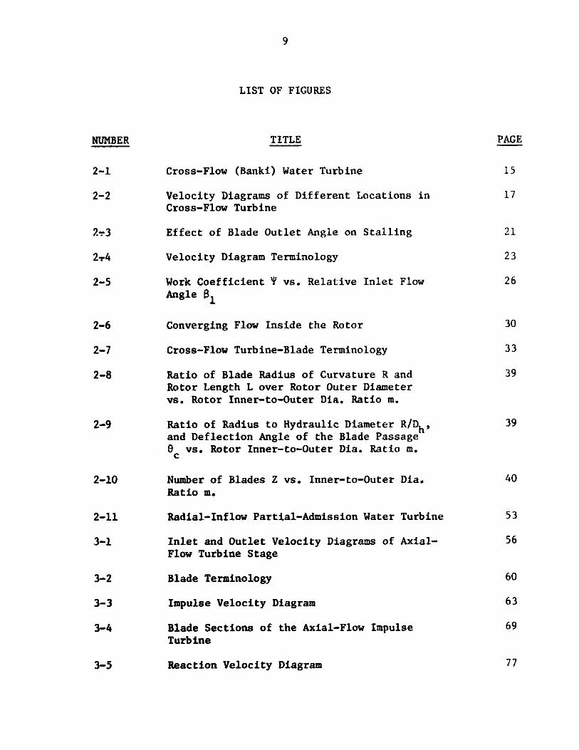
2.3 ANALYSIS OF THE MACHINE
The most useful relation in design of a turbomachine is the
Euler equation,
UiCoi - UoCeo = gc(ho ,- h. 0)
where U stands for rotor peripheral speed, C0 is the tangential
component of absolute velocity of the fluid and h. is the stagna-
tion enthalpy. Subscripts i and o stand for inlet and outlet of
the rotor, respectively (Fig. 2-1).
The rotor normally is designed so that the absolute velocity
of the fluid leaving the rotor is in the radial direction, so
Co -O
and therefore
UC gc A h.i-o
and then the parameter "work coefficient" for the rotor will simply
be
A(UC 0) C
2 u EU

17
FIG.2e2. VELOCITY DIAGRAMS OF DIFFERENT LOCATIONS INCROSSeFLOW TURBINE.

l8
From the first law of thernodynmitnlen,
- A h. 2- A he A (h + 2 + zg)
m 1-0 j-o
but for water turbines the rate of heat transfer and change in
static enthalpy are very small and for small units like the one we
are to study the drop in height from inlet to outlet is negligible,
so that,
-- Ah, - y(C2 - C2)
using the equations we had before,
U C 1 (C -C)2 2i i 2 (Ci C
'v2 1 2 2'' 2U2 (C- C 0 )
or finally
U- (C - C2) (a
For an impulse machine the value of T is normally taken
equal to 2.0. If the total hydraulic head before the nozzle is
AH, and riN be taken as nozzle efficiency (which covers the loss
of kinetic energy through the nozzle) then equation (a) can be
written as follows,
U 2 1 (2g AHn -C)

19
or C
U.= (AH, TN -0)(2.1)1 N 2
From Eq. (2.1) we find that for a given hydraulic head,
choice of the velocity diagrams enables us to determine the rotor
speed and hence rotor dimensions.
2.4 DESIGN OF THE ROTOR
The choice of the blade inlet and outlet angles is the
important part of the design. They have to be chosen so that the
jet of water transfers useful work to the rotor in both passes
through the blades.
Throughout this analysis angles are measured from tangents
to the circles and are positive in the direction of rotation. Also
we assume that- at design point the incidence angle is zero and the
deviation angle is very small so that the design will not be affected
if we assume the derivation to be zero. From Fig. (2-2) by simple
geometry we have for all cases
a2 = a3
This is true for all shaft speeds and flow inlet velocities. But
one may question why the inter stage angle of the blades is taken
equal to 90* (i.e. the outlet angle of the first "stage" or pass,
and the inlet angle of the second stage). The reasoning behind this
choice is as follows.

,d0(
Assume zero deviation angle for the flow leaving the blades
in the first pass; therefore, the flow relative velocity angle will
be equal to the blade outlet angle. Now suppose that the angle of
the blade at the outlet of first pass is bigger than 90* (Fig. 2-3a).
As you see there will be negative incidence at the second pass.
This time assume 82 < 900 (Fig. 2-3b). In this case positive
incidence will take place. Now as a comparison in Fig. (2-3c) the
situation is shown with 8 = 90.
Therefore the optimum blade outlet angle has a value around
900. Now assume 6 as deviation angle at outlet of the first pass
(Fig. 2-3d). If the blade angle is kept equal to 90* then there
will be an angle of incidence "i" so that i = 6 (in the inlet of
the second pass). Consequently if the blade's outlet angle is
slightly more than 900 (equal to 90 + 6/2) then the incidence will
be near to zero.
Normally the values of deviation angle are of the order of 20
to 8. Therefore the optimum value for the blade outlet angle is
between 91* to 94@* Obviously taking the blade angle equal to 90
would not cause much effect on the performance.
Because the cross-flow turbine rotor works totally at atmospheric
pressure there is no static-pressure difference from inlet to outlet
of a blade passage. Therefore the flow through a blade passage does
not accelerate or diffuse. In fact, blade passages do not fill with
water and flow passes through the blade passage as a jet deflecting

21
>5)
\7s
(a)
rn-rn
NJ(c)
\II
(b)
(d)d
FIG.2e3. EFFECT OF BLADE OUTLET ANGLE ON STALLING.

along the pressure side of the bl.ade. Consequently the flow will
have a constant relative velocity through the passage (in the absence
of friction) and the maximum flow will be determined by the smaller
area of the passage which is at the inner diameter side of the rotor.
The rotor specifications are then as follows (Fig. 2-4):
outlet relative velocity angle (first pass) S2 = 90* so from
Fig. (2-4a) C 2 = U2 and the absolute velocity of water leaving
the rotor is in radial direction (Fig. 2-4b) a4 = 900 .
Let us define
- C6 1
(Notice that in this particular case x is equal to the work
coefficient.)
andr
r2 and r1 are inner and outer radii of the blading respectively,
therefore
U2 _U3
1 4
The above definitions will help us to write simpler geometric
relations.
From Fig. (2-4a) we have
C01 C cosal - Cl cosa1U1 uI -C1 cos a1 +W 1 cosa1 (2.2)

21
Ce'
Wei-
Cr W
(a)
C63
usUU2
(Cb
(b)
FIG.2e4. VELOCITY DIAGRAM TERMINOLOGY.

24
Also,
Cr1 =C 1 sin 0 - cx) = W1 sin(t - Si) (2.3)
f rom (2.2) and (2. 3)
tan
X (tan Qy -tan a1 )
Therefore
= tan 1 ( X ) tan a) (2.4)
From the outlet velocity triangle (Fig. 2-4a)
2 22C2 = W2+ U
If we assume no loss of kinetic energy through the blade passage,
then the relative velocity of the water has to remain unchanged
along the blade passage, so using Eqs. (2.2) and (2.3) we have
2
C2 =1U1 ( si S + m2 . (2.5)
But
C2 = -(2.6)
2 cos a2 Cos a2
Combining (2.6) and (2.5) we have,
a2 = os-1 M2 (2.7)
tan(x
sin S+ m

25
From Fig. (2-4b) we have;
U3 1cos(-3) = ----- n=(2.8)
4 m W3 m tan a3
but as illustrated before at any condition x3 = a2 and if incidence
and deviation angles are assumed to be zero then SI = 54 so from
(2.8) we have:
tana2 = mcos5
-1 1
a2 = tan - s(2.9)2 M Cos8
Therefore we found two values for a 2 , one by using the first
"stage" geometry (Eq. (2.7)) and the other was found by using the
second-stage conditions. Putting these two values equal we get a
nondimensional relation between the design parameters m , x and
a1 ,as follows:
tanl 1 = cos1 m 2 (2.10)
tan al 2 2
(-x sins) +n$ 2

7
6
5
4
3
2
I
OL~Ar0
T 9 w V V V U
130
I
I140
I I
'sir
160-
I
- I I I I S I A I.
/00 'In INr) L30) t40gmo' %FU Uo %.W %or 3 1 m
FIG.2-5. WORK COEFFICIENT*rVS. RELATIVE INLET FLOW
160
a IABSOsLUTE INLETFLOW ANGLE-
V,
170 180
ANGLES .
170
9

27
Notice that (1t , x and tiI are related together by Eq. (2.4).
Now design curves can be drawn using Eqs. (2.4) and (2.10) which may
help to choose the right value of the parameters. Two useful curves
may be,values of x vs. 8I for different values of nozzle angle
(a1), and values of x vs. 81 for different values of m .
Figure 2-5 shows the design curves based on Eq. (2.4).
Solving Eq. (2.10) for the value of X we get
1 2x - m Cosa [ - 11] - 1 + 1 (2.11)
costaJ ' m cos 81
For any value of m and 81 the value of x can be found, or
vice versa.
2.5 LOSSES AND EFFICIENCIES
In cross-flow machines, blades are normally made of curved
bent strips of thin sheet metal. So small variations in inlet flow
angle could cause high incidence losses. Summarily the other losses
can be listed as: hydraulic losses due to skin friction and change
of flow direction in the nozzle and blade passages; losses due to
converging flow in open space inside the rotor; and mechanical
losses.
a) Nozzle losses
For nozzle a factor cv which acts as a velocity correction
factor can be used to define the losses due to skin friction and
converging flow, so

28
Cc = C1
v g2gAH0
or
C Cv \f2gAH
For the loss due to the curved nozzle passage the curve given in
Appendix I, will be used, provided a hydraulic diameter is
defined as
D 4 x flow area (2.12)h wetted perimeter
If the radius of curvature is R then the curve in Appendix I
provides the values of loss factor k versus deflection angle
for different values of R/Dh , where
W2H = K-Loss 2g
and W is the mean water velocity through the nozzle. Obviously
the mean values of R and Dh should be used to get a better
result.
b) Blade losses
I) Hydraulic-friction losses. The coefficient of friction
for the flow through blade passages can be found based on hydraulic
diameter, and using the curve given in Appendix I. So

29
H f - X --Loss h Dh 2g
subscript h stands for values evaluated on basis of hydraulic
diameter. "L" is the length of the blade passage and W is the
relative flow velocity.
II) Losses due to flow direction change. In this case we
can use the curve given in Appendix I, as for the nozzle.
c) Losses within the rotor
As seen in Fig. 2-6, the direction of actual velocity leaving
different blades converges to one point. This effect will cause a
change in flow direction entering the second set of blades.
As seen in Fig. 2-6 from simple geometry, the maximum
incidence angle "y" caused by this effect is half of the admission
angle "0". It is assumed that the central stream line remains
undeflected. Also the bigger the admission angle is, the closer
the right-hand side jets will get to the inner surface of the rotor
and that will cause negative work on the second pass. Therefore
the angle of admission has to be kept as small as possible. A
reasonable range of magnitude for admission angle is between 20* to
400. For these values of admission angle the loss due to this effect
is very small.
d) Efficiencies
Normally the overall efficiency for a water turbine is
defined as;

30
FIG,2-6. CONVERGING FLOW INSIDE THE ROTOR.

31
p E TihX T)n n h m Q
where Th is the hydraulic efficiency of the turbine, and covers
all the hydraulic losses across the blading. (See also Appendix
II).
AH - Hh -,loss
where AH stands for difference between hydraulic head of the
turbine inlet and outlet.
The term n m or mechanical efficiency covers all the losses
due to disk friction and bearings and so on and is defined as;
- T-Tloss
m T
where T represents the shaft torque.
Finally n is the volumetric efficiency which covers the
leakages and the flow which passes the turbine without giving any
power
Q - Qik
Q Q
where Q is the volume flow rate.
The important part of the evaluation of the efficiency of
a turbine is to find the hydraulic efficiency. This term is very

32
sensitive to the blade profile and flow angles (see Appendix III).
In order to get the hydraulic efficiency of the crossflow turbine
using Eq. (2.15), one has to write all the losses mentioned in the
last section in terms of hydraulic head.
2.6 BLADE DESIGN
As mentioned before the rotor in a crossflow turbine con-
sists of two end plates to which the blades are joined. Many
designs do not have a through shaft, so that the torque is trans-
mitted to the output shaft by the blades, i.e. the blades experience
all the bending moment due to torque transmission, all the blades
come under a relatively high periodic stress, as at each moment
only a few blades carry the whole flow. Therefore one would like
to avoid long rotor blades and blades with small radial chord.
Stiffer plates may be used to support the blades between
the two end plates and so allow longer rotors. Therefore for a
given power level and hence a specified volume flow rate, if the
rotor can be reinforced with stiffer plates one can go for
smaller rotor diameter and longer rotors and hence higher shaft
speed. The cost for these apparent advantages is that of the
higher complexity.
For the type of design we have chosen, we will only be
concerned with rotors having no stiffer plates. Also the blade
profiles will be segments of a circle. Therefore the blades can
be cut out of thin-wall tubes, or made of strips of thin sheet

33
<0
Ze number of blades
dim inner dia.
do! outer dia.
L ! length of rotor
FIG.2e7. CROSSeFLOW TURBINE-BLADE TERMINOLOGY.

34
metal rolled around a pipe. The most important parameter to be
specified is the ratio of inner to outer diameter of the rotor
"m" which affects most of the other rotor parameters, such as
length, number of blades, etc., effect of m on other blade
design parameters can be found using Eqs. (2.13a) to (2.13f)
which relate these parameters. (See Fig. 2-7 for blade
notation.)
0Y - = 0 (2.13a)
2y -4) = B- (2.13b)2
dc sin y -2 sin4) (2.13c)
R= s c/(2.13d)2 5if(O C/2)
d - dc cos y + d sin $/2 = 02(.02 (2.1l3e)
a = d sin u/Z (2.13f)
The solidity a is defined as the ratio of the blade chord
to the spacing of the blades on the inner-diameter side of the rotor.
It will be easier to work with the nondimensional forms of
Eqs. (2.13a) to (2.13f). Let's define

35
A 2 and R w0 0
then,
y = 6c/2 (2.14a)
2y- B - (2.14b)
2Asiny sin$ (2.14c)
= A(2.14d)2 sin y
cosy + sin /2 = (1-M) (2.14e)
A2
a = m sin Tr/Z . (2.14f)
As discussed in the last section the hydraulic loss through
the blade passage is a function of the ratio of the radius of
curvature of the blade camberline (centerline) over the hydraulic
diameter of the passage and the deflection angle of the blade.
Figure 2-8 shows the variation of the ratio of the rotor length and
the blade curvature ratios over the rotor outer diameter versus
values of rotor inner-to-outer diameter ratio. These curves show
that shorter and more curved blades result from using bigger
values of m.
I

36
As ment joned in Sect LIon 2. 5 the loss th rough tithe bI ade
passage is a funct ion of 1he ratio R/D1 and () , where 1) IS
the passage hydraulic diameter and 0c is the blade deflection
angle. Bigger values of R/Dh and smaller values of 0C give
us less loss. Both these parameters can be found in terms of
geometrical parameters introduced in Eqs. (2.13) and (2.14), as
follows:
as definedDhS 4 x flows dwetted perimeter
but as pointed out before, flow through the blade passage is the
deflection of a jet of water along pressure side of the blade and
so the jet thickness is fairly constant. Consequently the hydraulic
diameter of the blade passage can be determined by the inner-
diameter side of the rotor. By the aid of Fig. 2-7 we then have
D -4 x (Lxs)h L + 2s
The reason for defining the wetted perimeter as (L +2s)
is that the flow does not fill the passage fully. Only the blade's
pressure side and side walls guide the flow. If W1 is the
relative velocity of water through the passage and a is the rotor
admission angle then at the inner-diameter side of the rotor we
have:
Q - W1A W L -2- 6rd

37
but as m=..d /d ,then
L --11W m d
360 i W1 m o
Defining a E c/s and A = c/d (Eq. (2.14) therefore,
d XAdS c=c=. 3
0
Substituting these into the relation for Dh we have:
ddA
u mW da
D 360 1 oDh = A
360 m W1d
Dividing both the denominator and the numerator by d
and naming
C' E
IT d W
thea we have
C' A4- x-d
m a 0h C' A
m a

38
Also from Eqs. (2.14) we have the definition of
R
0
or
R = Cd
Therefore
C' 2XR -+-
R_ _m a
Dh 4- xm a
or
R_ _ (C'a + 2Am)Dh 4C' A
The parameter c' will be a constant value for homologous
units of this kind (turbines having similarity in geometry and
velocity diagrams). Figure 2-9 shows the variation of 6C versus
m and the variation of R/Dh versus m for different values of
solidity. From Fig. 2-9 we find that the maximum value of R/Dh
happens at values of m closer to unity as solidity increases.
With reference to Fig. I-1 (Appendix I) we find that the loss
factor for the range of deflection angle we have (between 41* to
58*) does not change much with variations of 0C but is strongly
a function of R/Dh , especially for lower values of R/Dh (values
from 1 to about 5). Consequently for a chosen value of solidity a,
the maximum value of R/Dh seems to lead to the efficient passage.

.8
.6
.4
.2
.7
N
--L
.8 .9 I.
U,
0
ANGLE OFDMISSION
NOZZ&,ANGLE
.8
-. 6
FIG.2-8. RATIO OF BLADE RADIUS OF URVATURE RAND ROTOR LENGTH LOVER ROTOR OUTER DIAMETER VS. ROTOR INNEReTO-OUTER DIA. RATIO m
So
'.5
U N E ' Iliillll
IUNEMAXIMUM
.5
'?68
.6
ANGLE OF ADMISSION300
NOZZLE ANGLE30
.- II
.7m
.9 i.
80
60
40
20
0
P19.2-9. RATIO OF RADIUS TO HYDRAULIC DIAMETER R/g , AND DEFLECTIONANGLE OF THE BLADE PASSAGE VS. ROTOR INNER-TO-OUTER DIA. RATIO m.
39
b'yM'l
.6
8
6
4
2
0LJ
0
.5
.
f

Iok
sc
60ACCEPTABLEREGION
000000*
1 40 IIIIIIIIIIIIIIIIIIIIIlljlllllllllllliiiiiil1111,11,1111111111111111,1111111111IIIIIIIIIIIIIIIIIIIIIIlljliiilllllllllllllllllo o oloo
7000FLINE OF
109X o7 08 160z
m
FIG.2-10. NUMBER OF BLADES Z VS* INNER-TO-OUTER DIA. RATIO M
Ton
MIAIMUM LOSS
I I
ROTOR ANGLE OFa
ALMISSION 30I I
Arr
U- aAF
AF,I-r-i
jm
Flir 0-y-I I
40
20 II IIqr
-LI -- dop-- -. dop- m
I II I I
120 1

41
The design of the rotors with no stiffer plates is more dominated by
mechanical design of the blades than by optimization to get the mini-
mum loss. Using Eqs. (2.14a) to (2-14f), the curves shown in Fig.
2-10 can be drawn.
These curves show the number of blades for each choice of
solidity and rotor inner to outer diameter ratio. As the number
of blades is reduced the rotor becomes longer because the throat
width is lessened (Fig. 2-8). Therefore although the blade chord
increases as the number of blades decreases the blades become
more flexible in bending. On the basis of stress and stiffness
conclusion, assuming typical material properties and thickness
(e.g. 2mm steel plate for the blades), we have let 18 as the
minimum number of blades.
When the number of blades is increased, the rotor can be
shorter, but the manufacturing difficulties for small workshops
become progressively more severe. We have chosen 60 as the
maximum desirable number of blades. Points inside the closed curve
drawn in Fig. 2-10, give better designs as far as losses and structural
stiffness are concerned.
2.7 SIZING OF A CROSS FLOW TURBINE
For a machine of this type working under constant head, the
velocity of jet of water leaving the nozzle is fixed (Section 2.4).
Therefore the choice of inlet absolute flow angle from the nozzle
affects the size of the rotor, a small nozzle angle being desirable.

42
As discussed in Section 2.5, the angle of admission should also
be kept small in order to reduce the losses within the rotor and
losses due to flow entering the blades in the second pass. The
angle of admission is taken equal to 30 in our machine. The inlet
absolute flow angle in a prototype designed by Banki was 160. In
that design the flow crosses the rotor on an approximately horizontal
line (i.e. the water entrance and draining points are on a horizontal
line). He used a cast casing incorporating the nozzle for his
turbine.
As we have tried to avoid complex structures and manufacturing
processes, our design does not have a cast casing like Banki's
design had. Rather we used a steel angle framework with sheet
metal covers; there will be a main cover around the rotor which
confines the water spray. The nozzle will be a separate part fixed
to the frame giving a nozzle angle of 30. That value resulted
in the least complexity of the structural design. (See nozzle rotor
combination drawing in Section 2.8.) So with reference to Section
2.4 the absolute inlet flow angle "Ila1 will be 1500. Draining will
be vertically downward.
From the fact that the work coefficient is equal to 2.0 we
have
C = 2U.
Assuming a total-to-total efficiency of 75% for the turbine
(nozzle and rotor), from Eq. (2.1) we get,

43
A(c0 ) - 69.20 m/S2
then
U1 = 5.88 m/s
C = 13.88 m/s
W 1= 9.00 M/s
The choice of shaft speed depends on how large the rotor
outer diameter can be and what are the speed limitations for the
bearings. As we were to use wooden bearings the sliding velocity
between shaft and bearing bore limited us to a shaft speed of
300 rpm. This speed is lower than desirable, because a high
gear up ratio is needed to reach the shaft speed to 1800 rpm
(generator speed). In future design studies it would be justifiable
to specify bearings to run at high speeds.
Therefore specifying N = 300 rpm we get
d = 0.3743m.0
We would like to join the blades to the side plates by rivets
(see general arrangement drawing and nozzle-rotor combination
drawing in Section 2.8). Therefore we would like to have the least
possible number of blades in order to get sufficient space for
riveting the bent ends of the blades to the side plates. Using
Fig. 2-10 in the last section we get m = 0.6 and 24 blades.

43
Now using Kqs. (2-13a) to (2-13f) we get the following
results and blade parameters. First from the velocity diagram
(zero incidence) we get
B = 1300 53'
and then
6 = 520581c
Y = 260 29'
R = 0.0956 m
S = 0.0293 m
C = 0.0843 m
we have previously chosen,
Z = 24
M = 0.6
The inner diameter of the rotor then will be
d = 0.2246 m .
If 20% extra power is specified to cover the mechanical
losses and the losses in the generator then the output shaft
power has to be 6 Kw. The volume flow rate required will be
Q = 4(UWC6) = 0.0867 m3/S
The length of the rotor then will be

44
L . =
-W d1 W1
0.164 n
a being the admission angle.
Once more recalling the velocity triangles shown in Fig. 2-4,
we can write the following relation
A(U CO)total= A(U C0) st pass
A (U C )2nd pass
A(U C0 ) = (UC - U 2 %2) + (U3c6 - U 4c0 )
but as we specified,
U2 -U3
C 2U1
U1 i
,Cg = 0 a04
C =C =U
nd A(U C) total2
= 2U1
Therefore
A(U c6)1st pass= - 2
1 22 2U2
=2U1-m U1,
22U2(l - 2
and
A(U C0)2nd pass2 m2U2
= U mU
or

45
The above retttons show that for a value of in 0.6 , the energy
transferred to the rotor in first pass is 82% of the total energy
and only 18% of the total energy is received by the second pass.
This means that as hydraulic losses within the rotor and the
entrance losses in the second pass do not affect the performance of
the turbine very much.
2.8 MECHANICAL DESIGN
The manufacturing processes under which the turbine is to be
made have been the most dominant parameters in the mechanical
design. The general arrangement drawing, scheme of the nozzle
rotor combination and an isometric view of the machine are submitted
in the following pages. Different parts of the machine are briefly
described as follows:
Rotor
The turbine has a squirrel-cage-shaped rotor, 380 mm O.D.
and 165 mm long. The optimum speed under the design head of 10 m
is 300 rev/min.
It has 24 blades, each blade being simply a circular segment.
Blades can be rolled out of 2 mm galvanized steel sheet (see Part 11
on the general arrangement drawing). They are joined to the rotor
side plates with rivets (Part 12).
The rotor has no drive shaft. Power is transmitted through
the bearing housing which rotates with the rotor, and the shaft
which goes through the rotor bearing supports only the rotor
(Part 14).

41
35
V
1~'9
H-
IT
1-
12
I'- I
I
3231 34 32
GENERAL ARAAGEMENT DRAWING OF CROSS FLOW MACHINE
35
12
15
14
z31

47
IAI
K?
am= ........
r
NOZZLE-ROTOR COMBINATION OFCROSS-FLOW TURBINE
7/
0
xooov /

48
ISOMETRIC VIEW OF CROSS-FLOW MACHINE

49
Bearings
The bearing housing, which is a short piece of circular
steel pipe, is welded to a circular plate which is fixed to the
rotor side plates with rivets (Part 13).
Bearings are made of a special oil-impregnated wood. Although
there are some limitations for the maximum permissible speed for
this kind of bearing, its low cost and simplicity makes it suitable
for low-speed applications. Furthermore it does not need lubrication.
It works in wet as well as in dry conditions. It requires no seal
(Part 15).
In our design the bearing rotates with the rotor, so equalizing
wear on the wooden bearing and increasing the bearing life.
Chain transmission
Power is transmitted from the rotor to the generator by means
of bicycle chain and gears. A 52-tooth gear is fixed to the circular
plate which is welded to the bearing housing (Part 21).
The generator has a constant speed of 1800 rev/min. A chain
and gear combination is used which gives a speed ratio of about six
from turbine to generator.
A complete hub and set of five chain cogs for a bicycle
derailleur gear is used for the second speed step up (Part 22).
The unnecessary gears in the gear set are replaced by spacers
and only an 18-tooth gear (being driven by a 52-tooth gear on the
rotor) and a circular plate with a central bore, the same as one cf
the gears, is fixed to the gear set. The latter circular p-ate is

50
be fixed with a 36-tooth gear being used for the second speed-up
step (Part 23). The last gear has 17-teeth and must be fixed to
the generator shaft. For the power level we have in this machine
a good lubrication condition should be provided for the chain.
The two-step transmission in this turbine makes it difficult
to incorporate an oil bath around the chain. As you will see in
Chapter 4 this machine would not be selected as the final choice,
so we did not do further improvements on its transmission system.
In order to increase the life of the chain and sprockets, we recommend
that two chains in parallel be used. Therefore two sprockets should
be installed side by side on each shaft.
Housing
The housing is completely made of thin galvanized sheet steel.
It has a fixed section which covers most of the rotor (Part 31), and
a removable door (Part 32), placed in the back of the turbine, for
servicing. It has a lifting handle and is fastened to the fixed
section with two simple latches (Parts 34 and 35).
Frame
The frame is totally made of angles, welded together. The
generator mounting is a steel plate welded to short legs and its
size may vary when using different generators (Part 38).
Nozzle
The nozzle is completely made of steel plates, welded together
(Part 41). The flow can be changed and set on different valves for
different output powers. This is possible by chaning the angle of

51
flap (Part 42). The semi-circular channel (Part 43) which is welded
to the flap has holes for different settings.
Warning: never change the flow while the turbine is
in operation
As the system works under a relatively high head, a change
of flow while the turbine is working can cause "water-hammer" in
the piping which can result in serious damage.
To avoid this there has, to be a gate valve before the nozzle.
The flow must be slowly reduced almost to the shut-off position
before changing the flap position. After setting, the valve must
be opened gently.
The possibility of installing a surge-tank as a shock
absorber has not been studied, because it would increase the size
and the cost of the turbine.
2.9 EVALUATION OF EFFICIENCIES
Knowing the size of different parts of the turbine the
hydraulic efficiency of the turbine can be found. Following the
method given in the last sections we get:
-h = 76%
This efficiency is the total-to-total efficiency and is very close
to our prediction, so the design is acceptable. Taking the effect
of the energy loss by drain flow into account we get,
nt-s = 6o% -

52
If a mechanical efficiency of 94% and a generator efficiency
of 90% is assumed then
Tit-sm = 56.5%
and
n t-su= 51%
(See Appendix II.)
2.10 RADIAL-INFLOW PARTIAL-ADMISSION WATER TURBINE
Description
This type of turbine is a potential alternative to the cross-
flow and axial types.
The turbine simply consists of a spiral-shaped distributor
with rectangular cross section which distributes the flow in two
opposite portions of its inner circumference, each one being an arc
of 800. The rotor blades are rolled out of sheet metal and are
fastened at one end onlyaround the circumference of the turbine
disk as cantilevers. The flow enters the rotor with a swirling
radially inward motion, passes through the blades while still in
the radial plane, and subsequently is deflected to leave the rotor
in the axial direction.
Flow Control
This type as described gives the possibility of controlling
the volume flow to the rotor under constant head. Therefore the
velocity diagrams would keep their design-point geometry and
consequently the tarbine would work at its design-point efficiency
through the whole range of power.

ROTATABLE SLEEVE
SPIRAL
NOZZLE BLADES
53
a. a I -
/I
FIG.2-11. RADIAL-INFLOW PARTIAL-ADMISSION WATER TURBINE.
BODY
BLADES
4
-UF
I
ROTOR
ROTOR

54
The control of the flow could be easily achLeved by reducing
the angle of admission. This could be done by installing a rotatable
sleeve between rotor and distributor. The sleeve would have ports
which could be brought more or less into alignment with ports on a
fixed sleeve to vary the admission area.
Dimensions
For specified head (10 m) and power output (5.5 kw) a turbine
of this type would have a diameter of about 220 mm when turning at
450 rpm. However, with this size of the rotor there would be drain-
ing problems on the inner side of the rotor.
Unfortunately, increasing the rotor diameter brings out
another problem which is the spiral geometry and size (see Fig.
2). To solve the draining problem by increasing the diameter to
340 mm would reduce the axial width of the rotor to 55 mm and the
speed to 300 rev/min.
This would require a spiral distributor of the same width
(55 mm). To keep the fluid velocity in the spiral small, the radial
dimension of the spiral would have to be increased.
Conclusions
A rectangular cross section of the order of 60 x 200 mm would
result (in entry port). For the range of specific speed in which
we are working, dimensions as large as this make the radial inflow
turbine unattractive. We have not taken the design further.

55
Chapter 3
DESIGN OF AXIAL-FLOW TURBINES
3.1 DESCRIPTION
In this chapter the task is to design some simple axial-
flow turbines as a solution to the problem. We have chosen to
design machines with high hub-to-tip-diameter ratio which enables
us to use untwisted blades for the blading.
Principally, water flows through a set of nozzle blades
(installed all around the circumference of the hub disk), into the
rotor blades, then passes the rotor blades and through the diffuser
to the tailwater. The turbine can be designed as an impulse or a
reaction machine.
3*2 ADVANTAGES
These designs should have comparable advantages with the Banki
type. The design of these machines provides easy manufacturing
processes if they are to be mass produced (i.e. sand casting and
plastic moldinb).
The blades are made of molded, extruded or cast plastic
which will give accurate profiles and consequently a better design
and off-design performance. Moreover the shaft speed in these
machines is higher than that of the Banki type and therefore a
simpler transmission and a lower gear-up ratio will be needed. These
machines can also be used as a drive motor to drive other machines
besides the generator.

NOZZLEBLADE
CeI
ROTORBLADE
L,24-
FIG.3-l. INLET AND OUTLET VELOCITY DIAGRAMS OFAXIWL-FLOW TURBINE STAGE.
3, C 1
a2CX2

57
3.3 ANALYSIS
Similar to the analysis shown for the cross-flow turbine, we
can write Euler's equation to relate different velocity-triangle
specifications together (Fig. 3-1).
h01 -h02 1 C61- U2C02 . (3.1)
But if AH0 is the total hydraulic head difference across the
rotor then
h01 - h02 ttAH g (3.2)
where ntt is the total-to-total efficiency of the turbine (see
Appendix II).
The three parameters: flow coefficient, work coefficient
and reaction which specify the type of the velocity diagram and
blading are defined respectively as follows:
C
S- - (3.3a)
U1Ce - U2C02
2 (3.3b)
C20( + C362
R S 1- 2U (3.3c)

58
The analysis is done for the mean diameterfor the usual
case where C retains constant from inlet to the nozzles to
outlet of the rotor. Now for each design a velocity triangle can
be chosen, hence values of 4, $ and R can be specified.
A good approach to the design of different machines of this
type with different degrees of reaction is to keep the inlet flow
angle to the rotor "a " constant and to vary the two other parameters
(i.e. R and $).
From (3.2) and (3.3b) we have
Us= t g .0(3.4)
Now, choice of shaft speed gives us the mean diameter
d 60 U (3.5a)m W (RPM)
and
d - dt + dh (3.5b)M 2
and mass flow rate will be
W (3.6)A(U C)
where W is the output power of the turbine.

59
The annulus area then will be
A & -m
p(3.7)
where p is the density. Also we know that in terms of hub and tip
diameters the annulus area will be
Aa = (d~ - dh) (3.8)
As mentioned before we try to keep the ratio of hub to tip diameter
high enough, to be able to use untwisted blades. A reasonable
value for this ratio is around 0.8.
Now, a choice of velocity triangle gives us the value of
A(U C0 ) and hence from Eq. (3.4), (3.6) and (3.7) the values of
UAa are found. Then the shaft speed can be determined and using
Eq. (3.5a) gives us the value of mean diameter. Then using Eqs.
(3.5b) and (3.8) we can find dh and dt *
If the ratio of dh/dt is not acceptable a new shaft speed
has to be chosen to optimize the dh/dt ratio.
3.4 DESIGN OF BLADES
Figure 3-2 shows the terminology used in this design
procedure. To find blade angles from flow angles we may use the
inform tion and curves given in Reference (2). The following two
relations approximate the curves given in Ref. (2) with a good

60
BLADE WIDTHb
LEADING EDGE --
'4
FLOW INLETANGLE
atu Anr nar
IACLA
ILAUE IULEIANGLE
INDUCED INCIDENCEANGLE A-
STAGGER ANGLE
\TRAIL
FLOW OUTLETANGLE
BLADEANGLE
OUTLET
82
"DEVIATION ANGLE6
ING EDGE
FIG.3-2. BLADE TERMINOLOGY.
I

61
accuracy, for incidence and deviation angles.
A ind = 0.25(-70 - 1)(2.6 - a)a1 a1 -
0.08 + ( 60-A2
c/s36
(3.9)
(3.10)
Please see Fig. 3-2 for information on parameters used in above
formulae. These two formulae are useful in preliminary design.
In Eq. (3.10), 0c or blade turning angle is equal to
O c a 81 +Aind +0a2+ 6
so the blade angles will be
B1 81 + A ind
B2 - 82+6
Suggested values for leading and trailing edge radii are
r e - (0.03 to 0.05)C
- (0.02 to 0.01)C
and
rt

62
The design procedure for the blades is to choose a stagger
angle "A" and an optimum value for solidity a . The optimum
solidity can be estmated by the Zweiffel criterion for the value of
width-to-chord ratio;
b a 2.5 cos2 a(tgi + tgc 2) (3.11)
also from Fig. 3-2,
b Wcos A (3.12)c
from Eqs. (3.12) and (3.11) we find a ,
In steam and gas turbines the dimensions of the blades and
the number of the blades are normally determined by choosing a
reasonable value for chord as far as vibration and stresses are
concerned. In our case, as blades are short, a good choice for the
number of the blades which gives us a reasonable blade passage seems
to be a good approach.
Then finding the dimensions of the blades we can find the
blade shapes by trying different curves for the blade profile.
3.5 SIZING OF THE MACHINES
Single-stage axial-flow turbines are normally named on the

63
basis of their velocity triangles. Two possible and most common
types of velocity triangle are: impulse and 50%-renction.
The design procedure in each case is to guess a value of
total-to-total efficiency for the turbine. Then the machine will
be designed with respect to the estimated efficiency. Finally for
the designed machine the efficiency will be calculated using the
method given in Appendix III. The design can then be optimized.
In order to get 5Kw. electrical power from the generator
the turbine itself will be designed for 10% extra power. So the
specifications of the turbine are 5.5 Kw. output power and 10 m.
hydraulic head.
a) Depjgof an impulse machine
Assumptions are a total-to-total efficiency of 0.80 and
velocity-diagram specifications of: work coefficient of 20
(implicit in an impulse machine), and flow coefficient of 0.8 (which
gives an acceptable nozzle angle). Also we will specify that the
absolute velocity leaving the rotor is to be in the axial
direction, to minimize leaving losses therefore we have,
2C 2
AR0 - H01 - 0 - 2
from Fig. 3-3 we have,
C C
U
Fig. 3.3. IMPULSE VELOCITY DIAGRAM

64
Substituting the last two relations into Eqn. (3.4) and rearranging
for U we have:
n gHlU 2
2
applying numerical values we have (at mean diameter);
U - 5.90 m/S
so
m $U2 = 69.75 m2/s2
Then from Eq. (3.6) the volume-flow rate is
Q = 0.0791 m3/s
Then from the velocity diagram
a 1
{ 8
02
- 68.20
- 0
- 5l.34*
- 51.34*
and
A (UC e)

65
and
C1 = 13.26 m/s
W s aW2 -=7.38 m/s
C2 - 3.54 m/s
The choice of the shaft speed has to be done with regard to the
following considerations: a) the value of hub-to-tip diameter ratio
should be around 0.8; and b) a combination of two standard available
sprockets can be found which gives us 1800 rev/min on the generator
shaft. The minimum number of teeth for a 1/2"-pitch sprocket
spinning at 1800 rev/min is 24 teeth. This value is recommended
by almost all manufacturers. Therefore the value of shaft speed
gotten by specifying the hub-to-tip diameter ratio should lead to
an available number for sprocket teeth.
With regard to the above discussion a shaft speed of 540
rev/min gives 80 teeth for the big sprocket. The dimensions of the
rotor then will be
d - 0.2087 mU
Aa2
-0. 0168 m

66
and
dt = 0.2347 m
dh = 0.1827 m
blade height = 0.0260 m
The ratio of hub-to-tip diameter ratio is then 0.78 which is in an
acceptable range.
Blade design. Nozzle and rotor blades should be designed
separately for this machine as they have different flow inlet and
outlet angles.
First for nozzle blades: by looking through curves and
information given in Ref. (2) for different blade profiles, for
cases having the same deflection and inlet angle, an optimum
solidity of 1.5 and a stagger angle of 45* are suggested. (We
tried several profiles with other staggers but this value gave the
best-looking profile.)
From Eqs. (3.9) and (3.10) we have:
AGind - 19.250
6 - 5.09*
The blade angles are then
B: :19.25*
B 2 a 72.290

67
To
spacing.
choose the number of the blades we have to specify the
From the above specifications we have
b _ cos 45 - 0.71c
- 1.5s
(See Fig. 3-2).)
In this case a different number of blades
15 blades seemed to be a good number as it gives
sectional area for the blades (as we want to use
prefer to have blades with bigger chordal length
cross-sectional area).
With the above specification nozzle blade
follows:
sm
C
b
r t
were tried. Finally
a reasonable cross-
plastic blades, we
and hence more
sizes are as
= 0.0434 m
= 0.0651 m
- 0.0462 m
- 0.0025 m
- 0.0005 m
In the same way calculations for the rotor blades were
done. The results are tabulated in Table 3-1. Also see Fig. 3-4
for blade sections.
I I

aB a Z a P* AOd S B0 B2 S C b r rt 0
NOZZLE 0.0 68.2 15 1.5 45 19.25 5.09 19.25 73.29 43.4 65.1 46.2 2.5 0.5 12.4BLADES
ROTOR 513 51.3 16 1.5 30 5.13 6.27 56.34 57.57 40.7 61.6 53.35 2.5 0.5 21.8BLADES
TABLE 3-1: IMPULSE TURBINE BLADING DIMENSIONS (DIMENSIONS IN MM)

69
NOZZLE BLADES
PITOR BLADES
FIG. 34 9 DE-SECTIONS-OF INE.AXIAL,,ifLOWAMPULSE TURBINE,

70
Evaluation of efficiencies. With respect to the method given
in Appendix III and information we got about the blades the value of
each loss parameter can be found.
X N N X X Xpb pr pt pt ar
Nozzles 2.48 0.97 1.13 0.10 4.2 7.20
Rotor blades 9.04 0.80 1.12 0.10 1.2 20.20
TABLE 3-2: BLADES LOSS FACTORS
Substituting the numerical values for the parameters in the
equation for Ti and assuming 1 mm. radial clearance for the rotor
we have,
it-t = 80.6%
The assumed value for tt was 80%; therefore, we are close enough
to the optimum design.
Then from Appendix II we can find other efficiencies. We
specify that diffuser blades after the rotor will reduce the velocity
of the flow down to .75 of its value when it leaves the rotor so,
nt-s -75%
if mechanical efficiency is 95% and generator efficiency equal to
90% then the machine and the unit efficiencies will be;

71
at-sm = 71.0%
nt-sU 64.1%
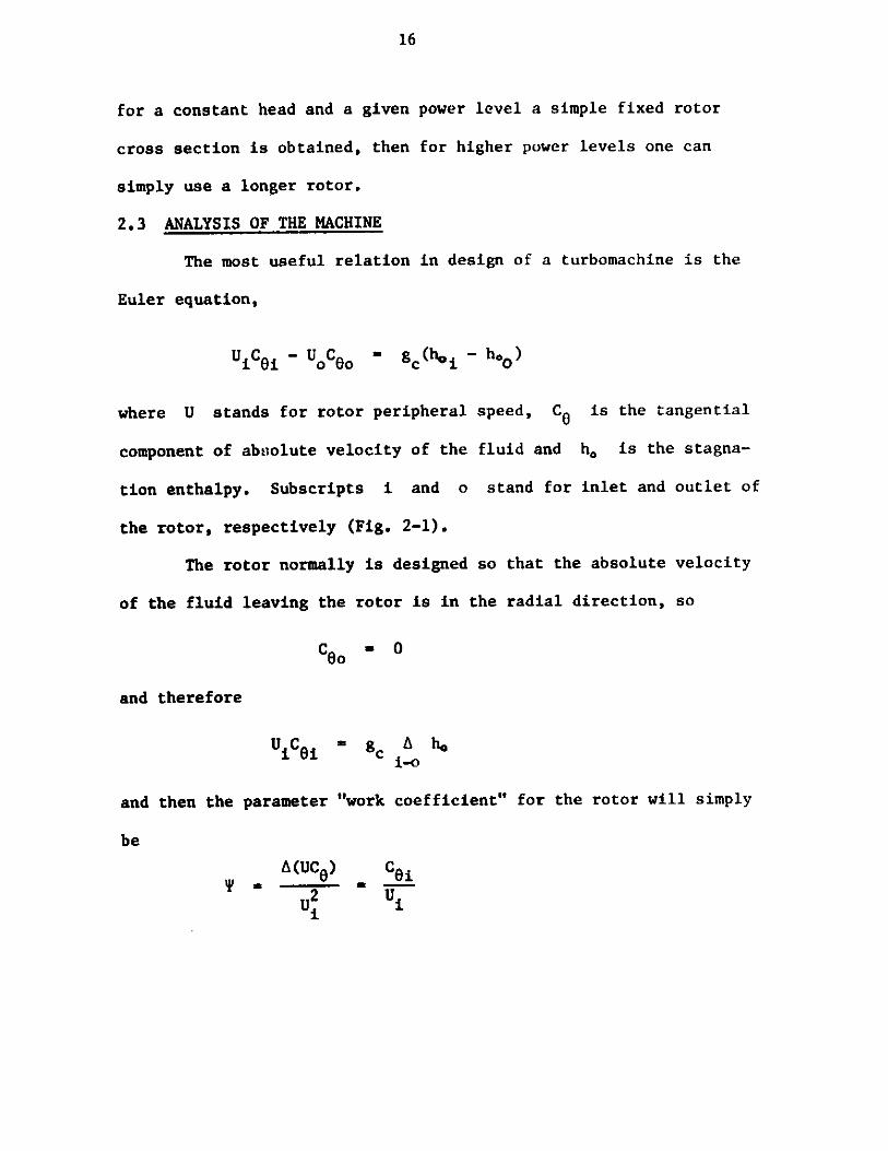
Mechanical design. It is not necessary to describe all the details
of the mechanical design in this report. Therefore only a short
description about different parts will be given. In the next pages
the general-arrangement drawing and turbine section drawing can be
seen. The machine is to run a 5Kw., 1800 RPM generator by means of
chain and sprocket transmission. Further descriptions are
individually given as follows:
Rotor-nozzle combination. This combination has high-accuracy
components to be made of plastic. The rotor (see drawing 1, Part 11)
has 16 blades. The up-stream nozzle blades (Part 12) with 15 blades,
and the downstream diffuser blades (Part 13) are molded into hubs
which act as bearings for the rotor. The nose up-stream of the
nozzle blades (Part 14) guides the flow to the nozzles.
These are all installed in a plastic bush (Part 15). This
bush gives a smooth inner surface to the duct surrounding the rotor,
a feature which will increase the efficiency.
Also this plastic bush allows us to use low-cost materials
(even rustable) for the center-section housing tube (Part 22).
The diffuser blades transmit the rotor-thrust-bearing force
to the center section.
3, 23 24 33
34
21
14 12
22 Is
AXIAL FLOW IMPLSE WICHIN CROSS SECTION
tZ *k
I. -
Ar
I
x
sEc. A- A
-ownsdu
'*A Jr%3N

000
I 1 36
(ENERAL ARi9AAGEMEN1" DRA WING OF AXIAL
1 1 I
Ar. K'1 __ - - II II .
I I II I I
I'I' 'II , )L./1 ~ 1 / I '5
I' I
A-
FLOW IP.rVJLSE MACHINE
1%
I
L
35
I.26
I

74
The bushing is fixed to the housing be means of a flange
molded to the upstream end (i.e. nozzle size), which is clamped
between the flanges of Parts 21 and 22. The nozzle blading is
fixed to the bushing by square-cross-section projections in the end
of each blade. These match up with slots in the bushing. After
assembly the blades are fastened to the bushing with resin adhesive.
The nose in front of the nozzle blading is also fastened to
the hub of the nozzles by structural adhesive. The diffuser
blading is similarly fastened to a flanged bushing, clamped between
the flanges of Parts 22 and 23.
The rotor bearings are lubricated with water. Water flows
in through the hole in the front of the nose and lubricates the
front bearing. Then some water flows to the back bearing through
small holes in the rotot hub.
Housing and frame. The housing has three individual sections which
are bolted together. The upstream section, Part 21, is actually an
adaptor. It enables us to connect the turbine to a standard 10"
water pipe and flange. The center section (Part 22) encloses the
turbine itself and the downstream section (Part 23) is the outlet
collector.
Different parts of the housing can be made of rolled steel
sheets welded to steel flanges. However, if there are local
facilities for sand casting, Parts 21 and 22 would be better made
from cast iron.

75
The frame (Part 25) Is made of steel angles welded together.
The turbine is bolted to the frame using some of the flange bolts
through the housing back plate (Part 24). The tpper plate (Part 26)
of the frame supports the generator. These are shown in Figure 2.
Transmissiop system. Power is transmitted from the rotor to the
output shaft by the means of a coupling disk (Part 31). This disk
has four slots on its circumference which match up with small teeth
in the bore of the rotor stub shaft.
As the disk is loosely in contact with the rotor it can
transmit only torque, and no bending moment or thrust force, to the
output shaft.
The output shaft (Part 32) is supported by a flange bearing
(Part 33) which is fixed to the housing back plate by bolts. The
flange bearing has a rubber seal in the drain side, which prevents
water leaking into the bearing.
The ball bearing in the flange bearing, together with a
tapered bush and a nut with locking washer, keeps the shaft in
the right position.
In order to raise the rotor speed to the generator speed a
combination of two sprockets is used with a tooth ratio of four
(Parts 34 and 35). The chain used in this system is standard 1/2"
chain (bicycle chain). The sprockets have 80 and 24 teeth on the
rotor and generator shafts, respectively.

76
We do not recommend the use of standard bicycle sprockets
in this case. To transmit five kw at a speed of 1800 RPM would be
loading them up to their maximum strength and would leave no safety
margin.
To fix the larger sprocket to the rotor shaft a split taper
bushing (Part 36) is used. This is done to avoid any need for
hammering or pressing on the shaft.
Using the unit in powers lower than five kw
To run the turbine at a power level less than five kw, the
flow to the turbine has to be reduced by the means of a value
installed at least a meter before the turbine inlet. Obviously
the turbine will work at its best efficiency when it is run fully
loaded.
Different possibilities for controlling the output power
by installing some kind of mechanism were studied, but all cases
result in a significant increase in size and complexity. I feel
that users would not find these possibilities attractive.
b) Desizn of a reaction machine
This section is concerned with design of a 50% reaction axial
turbine. The principles of the calculations are exactly the same
as for the impulse machine. Therefore only the assumptions and
tabulated results will be presented. In fact the structure of both
turbines are also the same, so to avoid repeating the mechanical
drawing of this machine it is not submitted as it is quite similar

77
to impulse machine. But a short description of the differences is
given in the following paragraphs.
The significance of the 50% reaction machine is that its
rotor and nozzle blades will have the same cross section. We
specify a work coefficient of oneyand absolute flow angle to the
rotor to be the same for both
impulse and reaction turbines.
The absolute flow leaving the -k
rotor will then be in theU
axial direction. The first FIG. 3-5: REACTION VELOCITY DIAGRAM
guess for the total-to-total efficiency is 85%. The result of the
velociLy diagram calculation is:
ai = 2 68.2
Ct,2 =0.0*
U - 8.84 m/s
A(UCO) - 78.08 m 2s or J/Kg
Q = 0.0704 m3 /s
ci
> c2
= 2 9.52 m/s
- C - 5 = 3.54 m/s
A suitable shaft speed for above results which can give an
acepetable dh/dt is 720 RPM. Therefore;

78
d
dh
blade height
d1/dt
- 0.2345 m
= 0.2615
= 0.2075 m
= 0.027
* 0.79
Blade design. For simplicity the rotor-blade section will
be used for both nozzle and rotor blading. But because of differences
between number of the blades for the nozzle and the rotor, the solidity
of bladings will be different. For preliminary design let's select
a stagger of 45, 15 blades for nozzle and 16 blades for the rotor.
From the Zweiffel criterion (Eq. (3.11)) for rotor blades we have
bs
a 0.86
also
= cos A 0.71
Then blade dimensions will be as follows (Table 3-3):
Z S b c AO in
15 48.76 39.3 55.3 20.0
6 By B26 96B 1 74B2
6.4 94.6 20 74.6
re
2.5
16 45.76 39.3 55.3 20.0 6.4 94.6 20 74.6 2.5
TABLE 3-3: REACTION-TURBINE BLADE DIMENSIONS.
rt
0.5
0.5
NOZZLEBLADES
ROTORBLADES

79
NOZZLE BLADES
ROTOR BLADES
FIG.3-6. BLADE SECTIONS OF THE AXIAL-FLOW REACTION TURBINE.

80
The blade cross-sections are shown in Fig. 3-5.
Evaluation of efficiencies. Using the method given in
Appendix III, the values of different loss coefficients are as
given in Table 3-4:
1Pb N N AX X Xb Npr pt Pt ar
NOZZLES 4.15 1.0 1.12 0.1 4.0 8.75
ROTOR 4.48 1.03 0.12 0.1 4.0 9.27
TABLE 3-4: LOSS FACTORS OF REACTION-MACHINE BLADING
Specifying 1. to 1.5 mm radial clearance for the rotor
blade on the tip then the value of total-to-total efficiency can
be found, which is,
St-t - 85.6%
For preliminary design this is close enough to the first guess, so
that the design is acceptable.
If we specify that diffuser blades will diffuse the flow to
half of its absolute velocity when leaving the rotor, then the total-
to-static efficiency will be,
nt-s - 83.6%
If 95% mechanical efficiency and 90% generator efficiency
are assumed as before then the machine and the unit efficiencies are,

81
tt-s i 794 t-Su = 71.5%
Mechanical design. The general mechanical design on both
impulse and reaction machines are the same. Therefore no further
details about this reaction machine will be given, other than to
mention the differences in size and performance. The output speed
of this machine is more than that of the impulse turbine, and the
turbine itself is slightly bigger in size, but there is not much
difference in the total sizes of the units (turbine, frame and
generator, altogether).
The diffuser blades and axial diffuser in this machine are
longer and give better diffusion, which results in a few points
increase in efficiency.
The transmission ratio is 2.5 and the same size chain (1/2")
is used with two sprockets having 24 and 60 teeth on the generator
and rotor shafts, respectively.

82
Chapter 4
DISCUSSION ON ADVANTAGES OF DIFFERENT TYPES
As seen in the last chapters, each of the studied prototypes
had individually some advantages and some disadvantages. Looking
at the problem from the view of a developing country, the price of
the turbine, the manufacturing processes under which the turbine is
going to be made and the type of maintenance and service needed are
important parameters in the choice of the best machine.
All machines are designed not to need skilled maintenance.
Therefore cost and manufacturing requirements have to be discussed.
The crossflow turbine gives both possibilities of being manufactured
locally in farming areas and/or being manufactured in industrial
areas and shipped to farms. But axial-flow turbines should be
made centrally and shipped to farms. The type of processes under
which the cross-flow turbine could be made are mostly intermediate
processes such as sheet-metals fabrications, but the axial-flow
turbines have. parts which need more sophisticated processes (i.e.
plastic molding, and casting, etc.). To satisfy the goals of the
Technology Adaptation Program it might be preferred to choose
processes which provide improvements in industry in the developing
countries. In that case encouraging industries such as plastic
molders may be of great importance.
The amount of labor which has to be put into making each
cross-flow turbine is much higher than what has to be done for the

83
axial-flow type. The axial-flow machines would probably be cheaper
because of automation and their smaller size when produced in large
numbers.
Comparison of the structures of the turbines shows that, the
high speed of the reaction machine is an advantage over the impulse
and cross flow machines, as it provides a lower gear up ratio to the
electrical generator, so that a simpler transmission and lower forces
in chain and sprockets are entailed.
For the kind of generator speed we have chosen the chain
must work in an oil bath and be well lubricated, otherwise it will
not last long even for the axial flow reaction machine. Therefore
the low speed of cross-flow turbine and its two-step transmission
mkes it unattractive, because a far more expensive transmission
becomes necessary.
A big portion of the price of each of the units is the
generator cost. The rest of the construction cost seems likely to
be similar for all units for small scale production. For large
scale production the cross flow will be much more costly than the
axial types. This is because the material cost for the axial flow
machines is small but initial investments for molds and dyes are
required.
Finally the efficiencies of the machines differ. While
there is often surplus water flow available a hish efficiency machine
requiring a lower water flow will therefore require less costly pipes,
channels, values and so forth.

84
The followin table shows the efficiencies of the different
machines.
Cross-Flow Axial-Flow Axial-FlowTurbine Impulse Turbine Reaction Turbine
t-t 76% 80% 85%
t-s 60% 75% 83.5%
t-sm 56.5% 71% 79.5%
t-su 51% 64% 71.5%
t-t E total-to-total efficiency of turbine blading
t-s E total-to-static efficiency of turbine blading
t-sm S total-to-static efficiency of machine (shaft power)
t-su E total-to-static efficiency of unit (electrical power)
Based on all considerations we chose the reaction machine as
the best solution to the problem.
4.1 IMPROVEMENTS ON REACTION MACHINE
The preliminary design shown in the last chapter has some
questionable features. Here we try to improve on that design as
much as possible. Following are some items which it seems necessary
to cover.
By looking at the general-arrangement drawing submitted in
this chapter (DRN. No. AF301), the difference between the rotor-
nozzle combinations in two schemes can be seen.

85
This improved design provides less hydrostatic force on the
rotor. The atmospheric pressure is bypassed through the rotor
central hole to the other side of the rotor, hence equalizing the
pressure on the two sides of the rotor and reducing the axial force
on the rotor. The aliding surfaces between the rotor and diffuser
hubs are covered with thin stainless-steel sheets which reduce the
friction and give a long life. (For the high pressure and velocity
on sliding surfaces even the best kinds of plastic can not last and
they melt.) Lubrication of these surfaces is possible by the aid
of holes in the rotor hub and grooves on the plates. The lubricant
water is supplied from upstream through the holes in the stator hub.
The front adaptor in the improved machine is changed. The
new adapter enables us to connect the turbine to 8" diameter piping.
The smaller tube and valve size reduces the cost.
The oil bath in the back of the turbine provides good
lubricating conditions for the chain and sprockets, and hence
increases the transmission system's life.
The blade profiles are also changed. The new blades have a
settling angle of 38* and their shapes are also optimized for the
best performance.
4.2 Off-Design Performance
The type of flow control we recomend for the machine is to
use a gate valve installed one m. ahead of the machine. The basic
assumption is that the turbine is going to be run under fairly steady

09,
08
97
400 800 1000 1200
QI CONSTANT
SHAFT SPEED R.PM.
FIG.4-1. CHARACTERISTIC CURVES OF REACTION MACHINE FOR CONSTANT FLOW RATE.
- 160
lgoE
120Iu
ixcl
-so $w
60X
40
20
-01400
0
.
6
'5
Nob
0
u
0)
I
.4
.3
2
1
.00 200
.
.0
am mm

09 s0
08No7 P..70
Lu 6 5 0L4
040f.
23Q0
20.02
.1 10
.0 060 40 45 50 55- SO 65 70 7FLOW RATEorlo
FIG.442. CHARACTERISTIC CURVES OF REACTION MACHINE IN CONSTANT SPEED.

88
loads. Therefore the required power can be set on the machine
and sli ht c4anges in frequency up to 5% would be acceptable.
re ophiskicated systems to control the turbine will
cause b g in reases in size and price of the machine which makes
the machine unattractive to customers.
based on this assumption the characteristic curves of the
turbine are shown in Figures 4-1 and 4-2. These curves are theo-
retical curves and based on predictions. The off-design performance
is predicted using the method given in Ref. (3), which has been
found to have a high degree of accuracy.
4*3 WORKING DRAWINGS
Following are the complete working drawings of the modified
reaction machine. Each drawing has a reference number. Using
these reference numbers all information about each part can be
found from tables provided. Special information on material, type
of manufacturing process under which the part should be made or sub-
drawings are given under "Remarks".
For the case of complicated parts, drawings for additional
sections or subparts are submitted which are marked by letters A,
B, C, etc. after the master part's reference number. (AF300 stands
for "axial-flow reaction turbine".)

- I
000,,,AF335
AF325
AF329
AF326
"I'AF332
-IAF323
AF 324
AF311
AF314.,
AF331
AF327
4F313
F318
001
AFMO
ffol
.AFV7
AF*32 -
AF320,
AF315111
-s.
,AF321
', IAF322
AF316
AFMI A
AF334--- Af
AF327-AF334
AF301

PART NUMBERNUMBER NAME OF PART OFF MATERIAL REMARKS
AF311 FRONT ADAPTOR 1 CAST IRON
AF312 MIDDLE SECTION 1 CAST IRON HOLES OF FLANGES SHOULDBE ALIGNED
AF313 DRAIN CHUTE 1 STEEL SEE SUBDRAWINGS
AF313A BACK PLATE 1 1O.t1 PLATE
AF313B FRONT FLANGE 1 15MM PLATE
AF313C CURVED PLATE 1 8MM PLATE
AF313D SIDE PLATE 2 5MM PLATE
AF313E FRONT PLATE 1 51 PLATE
V nn un

PART NUMBERNUMBER NAME OF PART OFF MATERIAL REMARKS
AF314 NOSE SEE ADJACENT TABLE FORPROFILE COORDINATES
AF315A SEE AF317 FOR BLADESAF315B STATOR BLADING PROFILE.AF315CAF315D
AF316A ROTOR BLADING 1 GLASS-FIBER-REINFORCED THE 1.5W1 STAINLESS-STEELAF316B POLYESTER THERMOSET SHEET SHOULD BE JOINED TOAF316C POLYESTER RESINS SLIDING SURFACE BY METAL-
30% GLASS BY WT. BONDING. EPOXY.
AF317 NOZZLE AND ROTOR SEE ADJACENT TABLE FORBLADE SECTIOt. BLADE PROFILE.
AF318A DIFFUSER BLADING 1 GLASS-FIBER REINFORCED THE 1.5MM STAINLESS STEELAF318B POLYESTER THERMOSET SHEET SHOULD BE JOINED TO
POLYESTER RESINS SLIDING SURFACE BY METAL-30% GLASS BY WT. BONDING EPOXY.
AF319 DIFFUSER-BLADE SEE ADJACENT TABLE FORSECTION BLADE PROFILE.
AF320 BUSH 1 GLASS-FIBER REINFORCEDPOLYESTER THERMOSET.POLYESTER RESINS30% GLASS BY WT.
'01-4

PART NUMBERMLANUMBER NAME OF PART OFF MATERIAL REMARKS
SLOTTED DISK
KEY
1
24 1 +
SHAFT
HUB ASSEMBLY
HUB HOUSING
FRONT CAP
BALL BEARING
SEAL
(3/16"x32)x5/16"BOLT
1
I1
I
I
3
ALUMI NUM
HARD STEEL
STAINLESS STEEL
CAST STEEL
1.5MM STEEL SHEET
M.R.C. BEARING 206-SXADAPTER AND NUT G-Y
GARLOCK 78X 0542
COMP NO. 26448-05DES. GRP. D.
EQUIVALENT STANDARDPARTS WITH THE SAME SIZECAN ALSO BE USED.
ROUND HEAD
____________ j______________________________________ .1 _________ 1 a -~------.------------------------
AF321AAF321B
AF322
AF323
AF323AAF323BAF323C
AF323D
AF323E

PART NUMBERNUMBER NAME OF PART OFF MATERIAL REMARKS
AF324 BIG SPROCKET 1 BROWNING 40P60 NO. OF TEETH 60TYPE 4 PITCH 1/2"BUSHING P1 PITCH CIRCLE DIA. 9.554"
FOR TYPE 40 CHAIN
AF325 SMALL SPROCKET 1 BROWNING 4024 NO. OF TEETH 24PITCH 1/2"PITCH DIA. CIRCLE 3.831"FOR TYPE 40 CHAIN
AF326 CHAIN I BROWNING NO. 40 1/2" PITCHNO. 40 A.S.R.C.

PART NUMBERNUMBER NAME OF PART OFF MATERIAL REMARKS
AF327 FRAME I STEEL
AF327A SIDE ANGLES 2 + 2 80x8Ox8 L 2 OFF AS DRAWN
AF327B TOP ANGLE 2 80x80x8 L OPPOSITE HAND
AF327C TOP PLATE 1 80M PLATE
AF327D BAR 2 40x8 FLATBAR
AF327E FOUNDATION PLATE 4 10MM PLATE
AF328 OIL BATH 1 2 AND 3W! STEEL SEAMWELDEDSHEETS
AF329 OIL-BATH COVER 1 2MM STEEL SHEET

I,PART NUMBER
NUMBER NAME OF PART OFF MATERIAL REMARKS
AF330 GENERATOR 1 WINCO INC. 4 POLE, 5KW, 115/230 VOLTSSERIES 5KS4G-3 21.7 AMP.
60 CYCLE1800 R.P.M.
-_ 1 PH.
AF331A (5/8"x12)x2 1/2" BOLT 20
AF331B 5/8"x12 NUT 20 HEXAGON HEADED
AF331C 5/8" LOCK WASHER 20
AF332A (1/2"x12) 1-1/2" BOLT 4
AF332B 1/2"x12 NUT 4 HEXAGON HEADED
AF332C 1/2" LOCK WASHER 4
AF333A (9/16"x12)x2" BOLT 4
AF333B (9/16"x12)xNUT 4
AF3330 9/16" PLAIN WASHER 4
AF333D 9/16" LOCK WASHER 4
AF334 ALIGNMENT-PIN 4 HARD STEEL
AF335A (3/8"5<16) 2" BOLT 1 HEXAGON HEADED
AF335B 3/8" PLAIN WASHER 2
AF335C (3/8'546) WING NUT 1

01
2H)
S
70208 NOISES *20
LIISWOt
I4
NS
10oC%4K)
S
2 HOLES HS8
8 HOL ES 0_2V
AF31I

r 20
mr
2
I1
~~1
F
20
AF312
cj
U.
LL
IrL 1 -
28HOLESHS 8
8 HOLES 020
0
1-
1
e

AF3 / 3
0 0
I
AFl/3 A
AF313 C 0000 aamb0 ;v top 4
O;p
0
4%%b
400004001P
loop
dow
eloooo
A FS3 8 40 mmmmlm 0 d
4
AF313 E 4 F313 D

S S ~-
00l.
go13.
4 HOLES 920
-r!&W
I0me
AF313 A
4 HOLES *16
U
0I.
1390
4 HOLES 016
6

2 HOLES 0 8
16
A HOLESFI0
AF3 13 B

a
AF313 C
.37' 180

0N)
6-
AF313 D
0 175
Cj
5-pW

00ft)
825
__ I
390
5-a
I-a0
A)
2 HLES020
AF313 E
L 195 _
r

K 66;
A -~
~=1
104
90 a
00
*S
q r
ryo
Lim

105
Xrmm
0.02.55.07.5
10.015.020.025.030.035.040.050.060.070.080.090.0
100.0110.0120.0130.0140.0150.0160.0
y mm
0.020.025.531.536.045.051.056.562.066.070.077.082.087.091. 595.098.0
100.0101.5102.5103.0103.5104.0
__0__-_-1.__ m
ir-
mn

0284
*208
0178
2
020
t ts
SM
a~
L.E
EE
IZU
ULW
-LIL
* 2
I*1
561
-
0 17
6-' #9
20
192edW
0
tv
____
____
____
__
U
-
3L
ilO
014
90 1'
it Tz4
Q31
--
--m
!MM
+01
0264
110
I

AF315 B
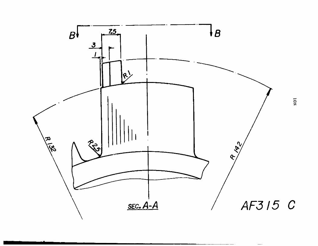
BI
4mA AF3
0
Mon-,
I I I
12, 1 1 11 1 1 1 6
I mommommolow & 0 lZ5
,sEc.

109
to)IV)K
A
ca'0Q
00
(30
wr3
I
'9o1
f) I

1 1 09F
00
1
1,01/0
0oe4
ml14
I+0
oiI
Ti -r)r)7
I
$O~ t
vol ii'
in..
min
.j .~
I'-
--=
Z~
0010
00
I&.:06i
1eoa 800
(0N0)
~3~
0V6t
39t~j0
--90 I7
.8
a -
A 7
I

A
AF3 16 5

IEl
sE A-A
I -
AF316 C
i io
i iIF-
I II

Rtotxe
R, =2.5 m
Rt-0.5 m
0.01.02.53.755.06.25
10.012.415.017.520.022.625.030.032.535.037.538.7540.041.2542.543.544.545.546.547.548.7550.0
4 mm4Yc mm
0.01.252.03.03.654.757.08.7510.011.512.513.2513.8514.013.8513.2512.612.011.2510.59.128.627.756.756.04,252.00.0
Xt mm trmmI0.00.760.861.01.181.431 .762.022.523.283.784.134.344.344.434.594.644.284.134.033.532.832.170.0
0.03.06.09.0
12.015.018.021.024.027.030.031.533.036.037.539.042.045.046.548.051.054.057.060.0
KW
I
I

114
CoN()
-w
Wa.S
I
00
I~1~/I
0
cc>
,
'I0 ,-()
901 0
10;
z.-ew
t,9J~
o0
0+
a-eeio
S ?91
5 a
9
v

sEc. A-A
AF318 B
]

I 16i
Q3)
R 1.i.omm
Rt=o.2 nu
x mm t mm
0.0 0.00.3 0.690.45 0.840.75 1.051.5 1.423.0 1.964.5 2.386.0 2.749.0 3.30
12.0 3.7315.0 4.0518.0 4.2821.0 4.4324.0 4.5027.0 4.4730.0 4.3333.0 4.0836.0 3.3739.0 3.3142.0 2.8445.0 2.3348.0 1.7951.0 1.2554.0 0.7357.0 0.2860.0 0.0

117
00
_[-I

,45
A
B
S EC. B AF320 B

119
co
06
--l
fig.
Q70c
f o x 1 ;

5
30 6 to
AF32 / B
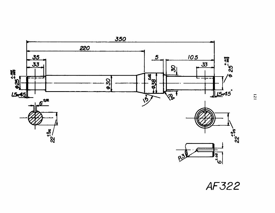
121
gjm~
1see0.-
100 4'I*11 0 1l
1~
rnLKf
qz~
t~
40
I'F'Eli
CE
-u
--
_a
.,
NiN~z
0 i&
I
m
m
sl-o0
FWC
0911 1
A

122
j76 06101
001*
990.9
10
0 8
-
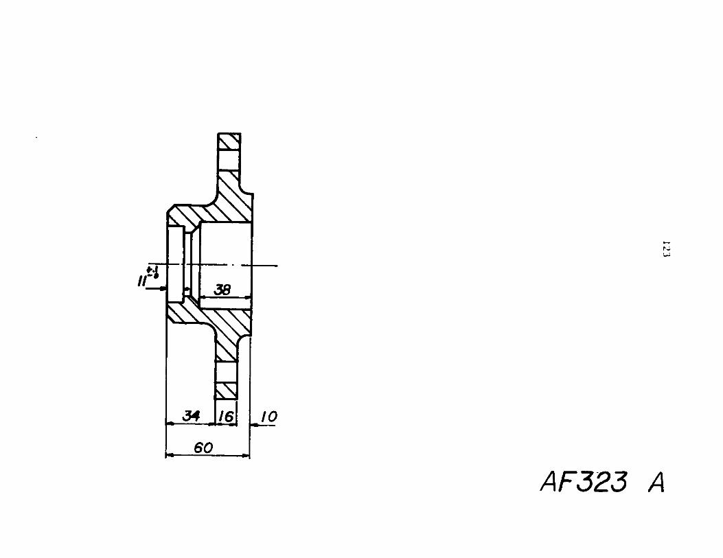
60
A F323 A

3hVLES 06
'.5
AF323 B

I2
I-...II-4
AWL -
Ll
0~
I)
Ip ~0N
)
-m
U
-
r 0
popm
k-K
9
I

r0C\%jr'oL.
126
ILZ
p
406

127
AO
PU
94*0j
opa *6

128
CLN)
ry)LL.
8I
$10*9"f

165
4I
~Ef~
I_=
Kg1280
fl 3131
A.410
Na
-1
(D
34
57
35
r
II
II
AF327

130
+n
I iieeii
A'tile'Iii-.
-k-i-
I I
I I
I ~
I I
I I
III
-I.III ~III
II
I-
an.
-I -
-ii-L
i~d
0o

80
AF327
574
1 I
A
I

40279z 258
2i11
KI
I- - 'o W--m
fl70~~ 00~~
I~JI
-I611i
'1I
AF32 7 B
(hl - - -- -I--
I
L

133
K~
NeN)
IF9
0n
v0
II

420olkIt1
80-
FCF4O~LL~i5
I
I0
0 20
EAF327 D
D
E

755
NK)K
GOFiCI
TXLzzzz
- U ~
I AT
a
120o
U-
---
A
N I
3
co
- -4
4 HOLES 0 16
AF328c, /'4
*4% -
I

170
265
a;jI
UQ06,40)
~4%
'C[~J
AF329
I-;0'
012
I

137
r)r)LA

138
APPENDIX I
FRICTION LOSS IN NONCIRCULAR CONDUITS
Pressure drop due to flow through a non-circular cross-
section bend can be found from;
2Ap K ZL
2
where K is the loss factor, v the average flow velocity and p
is the mass density. K is a factor of hydraulic diameter of the
cross-section and the radius of the bend, as well as the deflection
angle of the bend (Fig. 1-1).
The hydraulic diameter is defined as;
-h 4xflowareai v~ wetted perimeter '
and then pressure drop due to friction loss can also be expressed
in terms of Dh, as:
2
AP - h Dh 2
where L is the length of the conduit and fh is the friction
factor on the basis of hydraulic diameter. Obviously Re and
e/D should be defined an,
Re E Lv a and c/D 4c4v bDh
then f h can be found using Fig. 1-2.

139
r V V -.
R?
*/1.5
9.20
0.15
0.10
0.05
0
xrVALUES or R/b
80 100'DEFLECTION ANGLE
ML OSSFATOR FOR BENDS. (ASCE,J.HYDRAULIC DIV.,NOV. 65)
-. 4 ~e- 4
M ir r -
2
4
610
L tminor"IIN~ I1T
Turbulent
fr" ft-- -+++"--. - 44
-'. Drawn Tubing-Commercial Steel
Asphalt Cost IronGalvanized Iron
-Cost IronWood StaveConcreteRivetted Steel
SiI. . -
Li -- 4 A
f 16/Re5-
-1414t. feet0.0000050.000150.00040.00050.000850.0006-00030.001-0.010.003-0.03
te/D
f(Re(Circular Pipe Only):""lf I 'I' ''"'III''
103 104
1791
A---L .046'-"(Re) QZO
logsRe a VD/v
10.01,11W
0.004
00011
'Jvl
-I-+-'.++A!II--+-I-*.U.IUIf
106 10?
FIG.1e2.FRICTION FACTOR f VS. Re. FOR DIFFERENT e/D. (WN.M.Rohsenew andNY.Choi, Heat,Mass and Momentum Transfere , p 58 )
A0
0
0.02
0.015
0I..UCILz0
C)
ILS
0.010.0090.0080.0070.006
0.005
0.004
0.00210l
-]L--0-
W v W W Tl " -
7' 111 ITT~ " fm -+ -4+-+1111 . I, fill I I It I-T--T-T-TTTT-rTTTI
U J- j- j-F 1 11 111111-1 "11- IlI
'4-4-f -44 1 j.z L.r-I
0000,op-
'Wooo
000
ft .I&
20 40 60
Iii- I rns iti on o l-
vI
i v I v w v T.0.0,04

140
APPENDIX II
EFFICIENCIES
The total-to-total efficiency of a turbine is defined as
turbine output powerT1 t ~enthalpy drop from inlet total pressure
and temperature to outlet total pressure
This definition of efficiency is concerned with the blading hydraulic
losses.
The total-to-static efficiency of a turbine is
defined as,
Turbine output powert-s ~enthalpy drop from inlet total
pressure and temperature to outlet static pressure
This efficiency concerns the amount of energy going out of the
turbine by drain flow plus the internal losses of the blading.
For a turbine as a machine an overall total-to-static
efficiency of the machine can be defined which should include the
disk friction and other mechanical losses. That is
t-sm t-s m
where nm is the mechanical efficiency of the machine and defined
as,

141
Tr - T
m T
where T stands for shaft torque.
For a turbo-generator unit the efficiency of the generator
should also be taken into account which is
_ output electrical energyng ~input mechanical work
Then the overall efficiency of the unit will be defined as;
t -s n - x r ) xt-su t-s an g
See Fig. II-i .

142
ENERGY LEAVINGTHE TURBINE TOTAIL-WATER
K$2~
TOTAL HYDRAULICENERGY INTO TURBIW
HYDRAULIC LOSSES
MECHANICAL LOSSE
GENERATOR LOSSES
S
OUTPUT ELECTRICALPOWER
(GENERATOR)
FIG.Il-i. SCHEME OF LOSSES If WATER TURBO-GENERATORS.

143
APPENDIX III
PERFORMANCE ESTIMATION OF AXIAL-FLOW TURBINES
There are several ways to evaluate the efficiency of an
axial-flow turbine. The method given here which seems very
straightforward is based on the method given in the paper written
by H.R.M. Craig and H.J.A. Cox and published in the Institution
of Mechanical Engineering, Volume 185 32/71, 1970-71.
THE METHOD
For an axial-flow turbine stage, losses can be divided into
two groups. Group 1 losses are due to profile and secondary losses
of the nozzle and rotor blading, and group 2 losses are due to disk
friction, leakages, etc. Here we will be concerned only with group
1 losses. Therefore blading efficiency can be defined as
T1 work done in bladingt-tb- work done in blading + group 1 losses
It is convenient to evaluate the group 1 losses as loss
factors based on relative blade outlet velocities. Therefore,
C2 W2Group 1 losses - Xn + r
where Xn and Xr are the sum of loss factors due to profile and
secondary losses etc. for the nozzle and rotor, respectively.

144
Then to take the losses due to tip leakage and etc. into
account we have to multiply the value of blading efficiency by
the area ratio defined as follows;
A =Rotor blade swept arear ~ annulus area
Evaluation of loss factors
The blade loss factor is the sum of profile loss factor
Xp and secondary loss factor XS , where the former one is
defined as
XSX N N N + (AX) + (AX) + (AXp pb pi pr pt p pS/e p m
Each one of
Kp =Pb-
Npi
Npr
Npt
(AX)P t
(AX)/
(AZ ) 3
these are defined as:
basic profile loss
loss correction factor due to
loss correction factor due to
loss correction factor due to
profile loss factor increment
profile loss factor incrementradius
profile loss factor increment
incidence
high Reynolds Number
trailing edge
due to trailing edge
due to back surface
due to high Mach number

145
This method can acceptably be used for axial-flow water
turbines of the kind that this report is concerned with. In this
case for design-point preliminary design (AXp)m, (AXp)s and
N would be zero and the simple form for X will be
X = X N N + (AXp)tp pb pr p1 p
Each of these parameters can be found using curves given in
Figs. 111-2 to 111-6. The Reynolds Number is defined on the
blade opening as;
-W202 C101Re = - or
V V
See Fig. III-1 for the terminology of the blades.
The secondary-Loss factor can he found using Figures 111-7
and 111-8, where the secondary-loss factor X is defined as
XS= s)h/b s b
where
(Xs b basic secondary-loss factor
(Ns h/b2 secondary-loss ratio.

146
Guide blade /AC 6'
CA C
w-C r___________-lcence i
Back sir'aceArc :erqt% &s.,'e~ o/ rjj
length b-
40~
Fig. 1. Turbine blade and velocity triangle notation
1630 4 1 -
20Co F6 re
14-
30t0 On. i.F- c ;les
12 - -- - - q
i0 20 30 40 50 60 70 0 9P.U D CGU TSET AN;LE -B(Iow swed caict aon
Fia.eLift parameter. F,

147
3- - - -;--0- 4
'008
a
C
aOOC.o ,0
-1 0 0 02 03 Q4 05 URATiO0-.I. LIA
Fi.JS. Contraction ratio tar average profiles
40L0r -A v Iff - q -- 1
C43.5
:acS Contraction ratio
I 4
Tioso I0 S 0 0 80 9 0 I~ 2
MODIFIED LIFT COEFFICENT -j aS'b
Plg.4. Basic profile loss
Z 004 &/100
/Fi uteanqle0
"05cc
-2
angl
6150
00
01 04 006 0 1 1
TRAILNG - W"OE TH'CNESS To PIrCH R4:0, - eels
Fig. 5 .Trailing edge thickness losses
I I I I IK B Use low speed value 1-of outlet aftqie for a 1...4m ;asi pecaterJ ~ sisI5Il49 I,
07 0.8
I1.0
do

148
3J I [-I--.-
)(ks-eq wavicntsoild
2(1 r in s.ze)
a
00
:1 I Gstndo'd
le~ suWt4 to5 5E105 i06
REYNOLDS NUMBEqR e0 -bicsd on mioce OPeflig
Fi.6. Profile loss ratio against Reynolds number ef fect
altS9-'CaBA0h0
9-a
I
z,4
zc - ~ NN - _ __ _
14 25 )toj0 354
14 ~ ~ ~ 4 - - - -___
l-Z AO
uviast, ASPECT RATIO eflh
Meg. 7.econdabry bee-aspect ratio factor
'aq
5'a01-U'C
InIn0
-I
az0U
L5BACa
14
L10
-wO 02 04 0,6 06 10SQUARE OF T". '-01 P E i6MEANV:.3::TY
RATIO ACROSS 3LIA w" N r;e: tyjouit"e'.
Fig. 8. Secondary loss-basic loss factor
lz
101 1
wo I
4 4 ol
.OPto
2
16L

149
REFERENCES
(1) Axial Flow Turbines, J.H. Horlok, Robert E. Krieger PublishingCo., Huntington, New York, 1973.
(2) Investigation of Related SeriesCascade, J.C. Dunavent andCommittee for Aeronautics,
of Turbine Blade Profiles inJ.R. Erwin, National AdvisoryWashington, NACA. TN3802.
(3) Performance Estimation of Axial Flow Turbines, H.R.M. Craig,H.J.A. Cox, The Institution of Mechanical Engineers(Thermodynamics and Fluid Mechanics Group), Volume 18532/71, 1970-71.