Embed Size (px)
Citation preview
BULETINUL INSTITUTULUI POLITEHNIC DIN IAŞI Publicat de
Universitatea Tehnică „Gheorghe Asachi” din Iaşi Tomul LIX (LXIII), Fasc. 4, 2013
Secţia CONSTRUCŢII. ARHITECTURĂ
DESIGN OF TALL PRESTRESSED REINFORCED CONCRETE
TOWERS BASED ON DESIGN SPECTRUM AND TIME HISTORY ANALYSIS
BY
IOAN-COSMIN SCURTU* and VASILE MUŞAT
“Gheorghe Asachi” Technical University of Iaşi Faculty of Civil Engineering and Building Service
Received: August 1, 2013 Accepted for publication: August 16, 2013
Abstract. In this paper a case study for tall reinforced concrete tower
design is presented. The aim of this study is to develop a design method for concrete reinforced towers used to support wind power turbines, taking into account the particular design requirements related to the Romania's specific soil conditions and earthquake hazard. A spectral analysis was done using current design practice, and starting from these benchmark values, a more thorough time-history analysis was done with the a detailed model that took into account the soil–structure interaction phenomena.
Key words: reinforced concrete; finite element analysis; wind turbine; soil–structure interaction.
1. Introduction The new trend in global energy market is to develop clean, cheap and
sustainable energy sources. Since Romania is a windy region the development *Corresponding author: e-mail: [email protected]
76 Ioan-Cosmin Scurtu and Vasile Muşat
of wind energy sector has increased dramatically over the last decade. All the wind farms developed in Romania have used the hollow section tubular steel support system as bearing member for the wind generator, which is a costly and high maintenance demanding structure. This paper focusses on assessing the viability of prestressed concrete towers as a support structure for wind generators considering Romania’s high seismic hazard.
A dynamic analysis was performed, using three sets of ground motion data recorded at INCERC Iaşi Seismic Monitoring Station, during ’86, ’90 and ’77 earthquakes.
The results were crosschecked with the data obtained through response spectrum analysis using the response spectrum found in Romanian Earthquake Design Code P100 (NP123, 2010).
The response of the structure was monitored and the validity of the design assumptions was checked. Remarks regarding the soil-structure interaction phenomena are drawn and design guidelines that follow up the observed behavior of the structure are stated.
2. The Structural Model
For the purpose of structural modeling a complex 3-D model was
conceived. The model includes all the parts of a wind power generator including the nacelle, which is modeled through its corresponding mass that is added at the top of the support tower, the tower itself, made up from solid, 8 node finite elements, the foundation system and the surrounding soil (Fig.1 ). Emphasis is put on the modeling of the foundation system. The infrastructure is conceived in three different solutions.
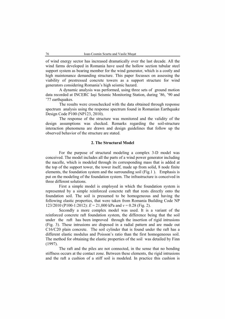
First a simple model is employed in which the foundation system is represented by a simple reinforced concrete raft that rests directly onto the foundation soil. The soil is presumed to be homogeneous and having the following elastic properties, that were taken from Romania Building Code NP 123/2010 (P100-1:2012): E = 21,000 kPa and ν = 0.28 (Fig. 2).
Secondly a more complex model was used. It is a variant of the reinforced concrete raft foundation system, the difference being that the soil under the raft has been improved through the insertion of rigid intrusions (Fig. 3). These intrusions are disposed in a radial pattern and are made out C16/C20 plain concrete. The soil cylinder that is found under the raft has a different elastic modulus and Poisson’s ratio than the first homogeneous soil. The method for obtaining the elastic properties of the soil was detailed by Finn (1997).
The raft and the piles are not connected, in the sense that no bending stiffness occurs at the contact zone. Between these elements, the rigid intrusions and the raft a cushion of a stiff soil is modeled. In practice this cushion is

Bul. Inst. Polit. Iaşi, t. LIX (LXIII), f. 4, 2013 77
necessary in order for the pilling equipment to move safely around the building site.
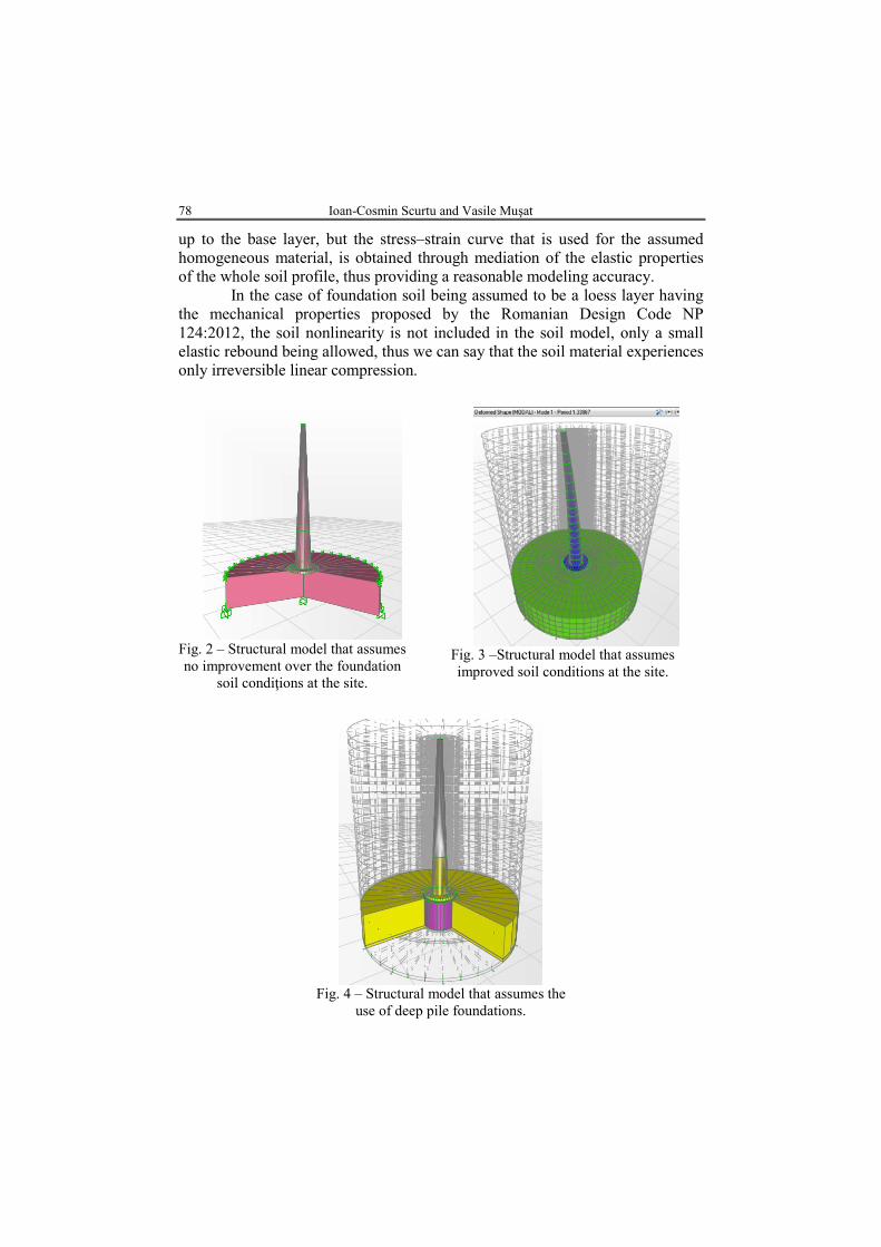
The third model under analysis uses a pilled raft foundation system. Piles are put close to the boundary of the raft spaced at 5D, D being the diameter of the pile. The soil under the raft is made up out of both a central and a peripheral zone that has the same mechanical properties that were used for the first model and a middle zone that uses soil material with improved mechanical properties, same as the one used in the second model from above (Fig. 4).
The piles used in this model have the same geometric and material properties as the ones used as rigid intrusions in the second model, the difference being that in this case the piles are fixed in the raft and can manifest great flexural rigidity.
The bearing mechanism is a combination of raft and pile foundation systems. The soil cylinder used to mimic the soil continuum is bounded at a far enough distance by fixed connections that restrain the model.
The models that incorporate the foundation soil into the analysis are a refinement of the cvasi-3-D model proposed by Finn (1997); great importance was given to the modeling of the soil response, implementing the algorithm for obtaining the mechanical properties of soil after energetic interpretation of the drilling records from the pilling operations that was described by Scurtu (2012).
Fig. 1 – Structural model that assumes fully clamped
conditions at the base of the tower.
The model proposed by Scurtu takes into account the nonlinear behavior of loess, which is the foundation stratum that is to be modeled into the finite element program SAP2000. The material is assumed to be homogeneous
78 Ioan-Cosmin Scurtu and Vasile Muşat
up to the base layer, but the stress–strain curve that is used for the assumed homogeneous material, is obtained through mediation of the elastic properties of the whole soil profile, thus providing a reasonable modeling accuracy.
In the case of foundation soil being assumed to be a loess layer having the mechanical properties proposed by the Romanian Design Code NP 124:2012, the soil nonlinearity is not included in the soil model, only a small elastic rebound being allowed, thus we can say that the soil material experiences only irreversible linear compression.
Fig. 2 – Structural model that assumes no improvement over the foundation
soil condiţions at the site.
Fig. 3 –Structural model that assumes improved soil conditions at the site.
Fig. 4 – Structural model that assumes the
use of deep pile foundations.
Bul. Inst. Polit. Iaşi, t. LIX (LXIII), f. 4, 2013 79
3. Analysis Data
With the purpose of structural soundness of the proposed structural
system (prestresed reinforced concrete tower) a comparative analysis was performed starting from a benchmark model that uses no foundation soil modeling at all. The base is fully clamped with no movement (rotations or translations) being allowed.
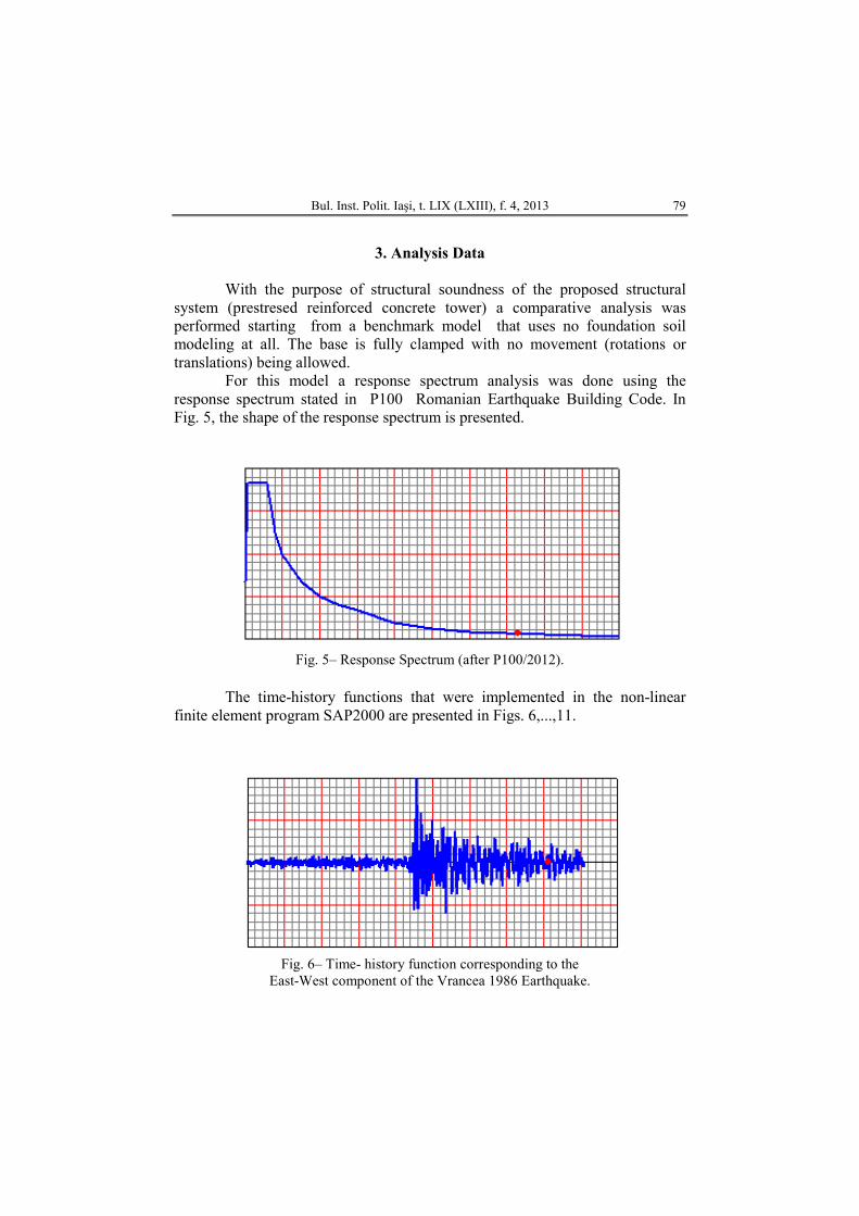
For this model a response spectrum analysis was done using the response spectrum stated in P100 Romanian Earthquake Building Code. In Fig. 5, the shape of the response spectrum is presented.
Fig. 5– Response Spectrum (after P100/2012).
The time-history functions that were implemented in the non-linear
finite element program SAP2000 are presented in Figs. 6,...,11.
Fig. 6– Time- history function corresponding to the
East-West component of the Vrancea 1986 Earthquake.
80 Ioan-Cosmin Scurtu and Vasile Muşat
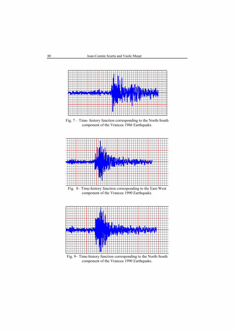
Fig. 7 – Time- history function corresponding to the North-South
component of the Vrancea 1986 Earthquake.
Fig. 8– Time-history function corresponding to the East-West
component of the Vrancea 1990 Earthquake.
Fig. 9– Time-history function corresponding to the North-South
component of the Vrancea 1990 Earthquake.
Bul. Inst. Polit. Iaşi, t. LIX (LXIII), f. 4, 2013 81
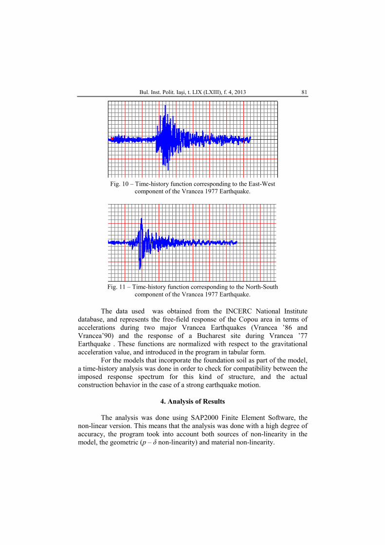
Fig. 10 – Time-history function corresponding to the East-West
component of the Vrancea 1977 Earthquake.
Fig. 11 – Time-history function corresponding to the North-South
component of the Vrancea 1977 Earthquake.
The data used was obtained from the INCERC National Institute database, and represents the free-field response of the Copou area in terms of accelerations during two major Vrancea Earthquakes (Vrancea ’86 and Vrancea’90) and the response of a Bucharest site during Vrancea ’77 Earthquake . These functions are normalized with respect to the gravitational acceleration value, and introduced in the program in tabular form.
For the models that incorporate the foundation soil as part of the model, a time-history analysis was done in order to check for compatibility between the imposed response spectrum for this kind of structure, and the actual construction behavior in the case of a strong earthquake motion.
4. Analysis of Results
The analysis was done using SAP2000 Finite Element Software, the
non-linear version. This means that the analysis was done with a high degree of accuracy, the program took into account both sources of non-linearity in the model, the geometric (p – δ non-linearity) and material non-linearity.

82 Ioan-Cosmin Scurtu and Vasile Muşat
In the case of the model in which the soils being modeled in the one layer, homogeneous loess hypothesis it was noticed only a small lateral displacement at the top of the structure compared with the results obtained for the other foundation systems. The stress state under the raft suggests that the actual behavior of the foundation soil will be different in the case of an earthquake. The contact pressure between the foundation raft and the soil exceeds over 700 kPa at some points. This will far exceed the loess’s structural skeleton resistance and will lead to excessive settlements and subsequent lateral drift larger than the one computed using the analysis assumptions.
A second analysis was done in the case of the raft foundation system that sits directly on top of the loess layer. In this analysis a mass-less soil volume having the elastic limit of 70 kPa was introduced. This assumption will give a more realistic structural response, due to the massive plastic yielding that takes place under the raft.
It was noticed that the use of improvement of the foundation soil can reduce the structural response in both terms of displacements at the top of the structure and effective stresses in the foundation soil under the structure.
In Figs. 12,…,14 are presented the response of all the structural models in terms of maximum displacements at the top and the maximum vertical and radial stresses for Vrancea ‘77 Earthquake which is by far, the most violent strong motion recorded in Romania.
Fig. 12 – Maximum displacements at the
top of the tower during Vrancea ‘77 Earthquake with direct fundations in loess
(values in mm).
Fig. 13 –Maximum displacements at the
top of the tower during Vrancea ‘77 Earthquake with direct foundations over improved soil condition (values in mm).
Bul. Inst. Polit. Iaşi, t. LIX (LXIII), f. 4, 2013 83
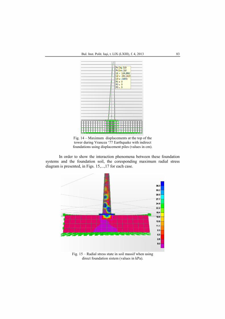
Fig. 14 – Maximum displacements at the top of the tower during Vrancea ‘77 Earthquake with indirect
foundations using displacement piles (values in cm).
In order to show the interaction phenomena between these foundation systems and the foundation soil, the coresponding maximum radial stress diagram is presented, in Figs. 15,...,17 for each case.
Fig. 15 – Radial stress state in soil massif when using
direct foundation sistem (values in kPa).
84 Ioan-Cosmin Scurtu and Vasile Muşat
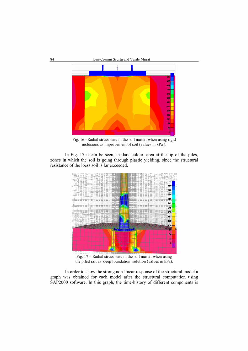
Fig. 16 –Radial stress state in the soil massif when using rigid
inclusions as improvement of soil (values in kPa ).
In Fig. 17 it can be seen, in dark colour, area at the tip of the piles, zones in which the soil is going through plastic yielding, since the structural resistance of the loess soil is far exceeded.
Fig. 17 – Radial stress state in the soil massif when using
the piled raft as deep foundation solution (values in kPa).
In order to show the strong non-linear response of the structural model a graph was obtained for each model after the structural computation using SAP2000 software. In this graph, the time-history of different components is
Bul. Inst. Polit. Iaşi, t. LIX (LXIII), f. 4, 2013 85
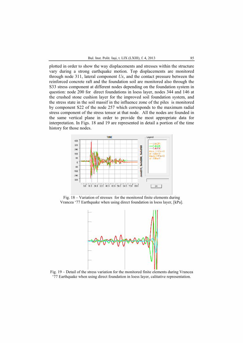
plotted in order to show the way displacements and stresses within the structure vary during a strong earthquake motion. Top displacements are monitored through node 311, lateral component Ux, and the contact pressure between the reinforced concrete raft and the foundation soil are monitored also through the S33 stress component at different nodes depending on the foundation system in question: node 200 for direct foundations in loess layer, nodes 344 and 146 at the crushed stone cushion layer for the improved soil foundation system, and the stress state in the soil massif in the influence zone of the piles is monitored by component S22 of the node 257 which corresponds to the maximum radial stress component of the stress tensor at that node. All the nodes are founded in the same vertical plane in order to provide the most appropriate data for interpretation. In Figs. 18 and 19 are represented in detail a portion of the time history for those nodes.
Fig. 18 – Variation of stresses for the monitored finite elements during
Vrancea ‘77 Earthquake when using direct foundation in loess layer, [kPa].
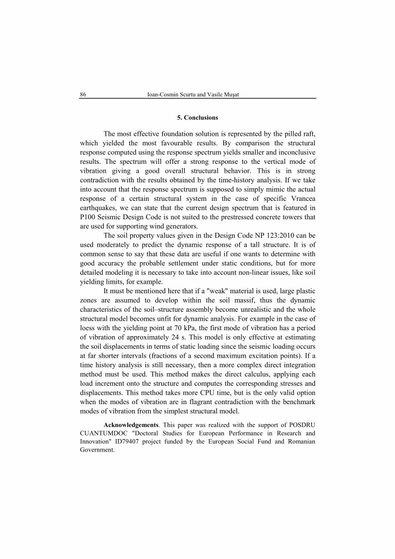
Fig. 19 – Detail of the stress variation for the monitored finite elements during Vrancea
‘77 Earthquake when using direct foundation in loess layer, calitative representation.
86 Ioan-Cosmin Scurtu and Vasile Muşat
5. Conclusions
The most effective foundation solution is represented by the pilled raft,
which yielded the most favourable results. By comparison the structural response computed using the response spectrum yields smaller and inconclusive results. The spectrum will offer a strong response to the vertical mode of vibration giving a good overall structural behavior. This is in strong contradiction with the results obtained by the time-history analysis. If we take into account that the response spectrum is supposed to simply mimic the actual response of a certain structural system in the case of specific Vrancea earthquakes, we can state that the current design spectrum that is featured in P100 Seismic Design Code is not suited to the prestressed concrete towers that are used for supporting wind generators.
The soil property values given in the Design Code NP 123:2010 can be used moderately to predict the dynamic response of a tall structure. It is of common sense to say that these data are useful if one wants to determine with good accuracy the probable settlement under static conditions, but for more detailed modeling it is necessary to take into account non-linear issues, like soil yielding limits, for example.
It must be mentioned here that if a "weak" material is used, large plastic zones are assumed to develop within the soil massif, thus the dynamic characteristics of the soil–structure assembly become unrealistic and the whole structural model becomes unfit for dynamic analysis. For example in the case of loess with the yielding point at 70 kPa, the first mode of vibration has a period of vibration of approximately 24 s. This model is only effective at estimating the soil displacements in terms of static loading since the seismic loading occurs at far shorter intervals (fractions of a second maximum excitation points). If a time history analysis is still necessary, then a more complex direct integration method must be used. This method makes the direct calculus, applying each load increment onto the structure and computes the corresponding stresses and displacements. This method takes more CPU time, but is the only valid option when the modes of vibration are in flagrant contradiction with the benchmark modes of vibration from the simplest structural model.
Acknowledgements. This paper was realized with the support of POSDRU CUANTUMDOC "Doctoral Studies for European Performance in Research and Innovation" ID79407 project funded by the European Social Fund and Romanian Government.
Bul. Inst. Polit. Iaşi, t. LIX (LXIII), f. 4, 2013 87
REFERENCES
Finn L.W. Soil–Pile–Structure Interactions. Geotechn. Special Publ., 70, 1-22 (1997). Scurtu I.C., Evaluarea caracteristicilor elastice ale terenului de fundare folosind
interpretarea datelor de foraj. Simp. Naţional "Creaţii Universitare 2012", 2012, 296-305.
* * * Normativ privind proiectarea geotehnică a fundaţiilor pe piloţi. NP123:2010. * * * Cod de proiectare seismică. P100-1:2012.
PROIECTAREA TURNURILOR ÎNALTE REALIZATE DIN BETON PRECOMPRIMAT FOLOSID SPECTRUL DE RĂSPUNS ŞI
ANALIZELE DE TIP „TIME-HISTORY”
(Rezumat) Se realizează o analiză comparativă între metodele de proiectare propuse de
normativul antiseismic românesc, P100, respectiv între cea uzuală, simplificată, bazată pe spectrul elastic de răspuns şi cea de tip „Time-Hoistory”, folosind 3 accelerograme reprezentative pentru zona seismică Vrancea. Astfel se doreşte evaluarea pe de o parte a viabilităţii turnurilor realizate din beton armat, ca soluţie de susţinere a generatoarelor eoliene în condiţiile de seismicitate din ţara noastră şi pe de altă parte evaluarea gradului de încredere asigurat de metodele simplificate de calcul seismic bazate pe spectrul elastic de răspuns.