Embed Size (px)
Citation preview

Design of the ARM VFP-11
Divide and Square Root
Synthesisable Macrocell
Neil Burgess
School of Engineering
Cardiff University
WALES, UK
Chris Hinds
ARM Design Center
Cambridge
UK

Key points
• New high-performance radix-4 SRT
square root (& divide) architecture
– There’s still life in the ol’ SRT yet...!
• Evaluation of Logical Effort
– vs Static Timing Analysis of synthesised logic
• Further Work…

ARM VFP-11
• VFP-11 is an implementation of the ARM
Vector Floating-Point Architecture
• Optimised for 3D graphics (vector) processing
– Divide & square root operations important
• VFP-11 is a synthesisable macrocell
• Co-processor for a high clock rate core
– target logic depth of 15 CMOS logic stages

N-R or SRT ?
• VFP-11 multiplications:– Launch new FMAC operation every clock cycle…
– … but takes 8 cycles to return result(9 cycles for double-precision)
• N-R on an FMAC with an n-cycle pipeline takes 3n+4 cycles (single-precision division)– (Schmookler et al – ARITH-14, 1999)
• Not good enough performance to compensate for locking up multiplier during div/root ops– (or compromise its performance by adding “flexibility”)

SRT it is then !
• Existing VFP implementation used radix-4
SRT with carry-propagate adder to update
remainder
– Based on Fandrianto’s work (late 80’s)
• Design decision was to stay with radix-4
SRT & find means of acceleration to
achieve required clock frequency

Statement of Problem
• Want to achieve single-cycle radix-4 SRT iteration in 15 logic stages (“LS”)– Logic stage ≠ logic gate (e.g. XOR gate has 2 LS)
• Critical path of SRT recurrence comprises:– Derive new result digit, qi+1
• Compare top few bits of remainder, Ri, with “constants”, Mk
– Update remainder by adding multiple of qi+1, Fk
– Update root estimate (sort of concatenate qi+1)
• Diagram on next slide…
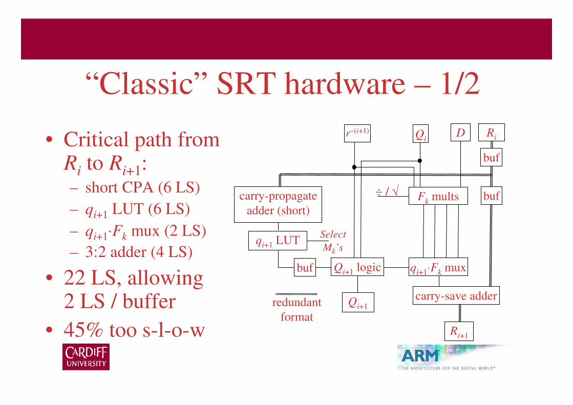
“Classic” SRT hardware – 1/2
• Critical path from Ri to Ri+1:– short CPA (6 LS)
– qi+1 LUT (6 LS)
– qi+1⋅Fk mux (2 LS)
– 3:2 adder (4 LS)
• 22 LS, allowing 2 LS / buffer
• 45% too s-l-o-w
Fk mults
Ri
Ri+1
qi+1 LUT
DQi
buf
redundant
format
carry-propagate
adder (short)
Qi+1 logic
r−(i+1)
carry-save adderQi+1
÷ / √
qi+1⋅Fk muxbuf
Select
Mk’s
buf

“Classic” SRT hardware – 2/2
• Parallelisation of
CPA/qi+1 logic &
Fk generation
• Merging CPA &
qi+1 comparisons
saves 2 LS
– Still 33% too slow
Fk mults
Ri
Ri+1
qi+1 logic
DQi
buf
redundant
format
carry-propagate
adder (short)
Qi+1 logic
r−(i+1)
carry-save adderQi+1
÷ / √
qi+1⋅Fk muxbuf
Select
Mk’s
buf

What we did• Kept msb’s of Ri
non-redundant– no short CPA
• 5-way Ri+1
speculation– CSA → MUX
• Used Qi+1+/− to
generate Fk
multiples
Fk logic
Ri[lsbs]
qi+1
Ri+1[lsbs]
M2
1-hot qi+1 logic
Qi+1+ & Qni+1
−
Qi+ & Qni
−D
buf
redundant format
8
cmp cmp
M1 M0 M-1
ck=sgn(trunc(Ri)–Mk) Q*i+1+/− logic
5:1 muxes
r−(i+1)Ri[msbs]
5:1 muxes
5 54-bit R*i+1 adders
(8 msb’s assimilated)
Ri+1[msbs]
buf
5
R*i+1 = Ri – Fk
÷ / √cmp cmp
buf
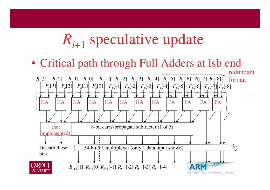
Ri+1 speculative update
• Critical path through Full Adders at lsb end
Ri[3]
Fk[3]
Ri+1[1] Ri+1[0] Ri+1[-1] Ri+1[-2] Ri+1[-3]
Discard these
bits
54-bit 5:1 multiplexer (only 1 data input shown)
8-bit carry-propagate subtracter (1 of 5)
Ri+1[-4]
(not
implemented)
HA HA HA HA HA HA HA HA FA FA FA
Ri[2]
Fk[2]
Ri[1]
Fk[1]
Ri[0]
Fk[0]
Ri[-1]
Fk[-1]
Ri[-2]
Fk[-2]
Ri[-3]
Fk[-3]
Ri[-4]
Fk[-4]
Ri[-5]
Fk[-5]
Ri[-6]
Fk[-6]
Ri[-7]
Fk[-7]
FA
Ri[-8]
Fk[-8]
redundant
format

Fk⋅qi update
• Used “on-the-fly” algorithm– Qi
+ & Qni− are root estimates, where Qni
− denotes !Qi−, but
without the trailing 1’s
• Square root Fk multiples derived as:– qi = 0: Fk⋅qi = 0
– qi = 1: −Fk⋅qi = !(2Qi+ ∨ 4−i)
– qi = 2: −Fk⋅qi = !(4Qi+ ∨ 4−(i-1))
– qi = -1: −Fk⋅qi = !(2(Qni−) ∨ 4−i)
– qi = -2: −Fk⋅qi = !(4(Qni−) ∨ 4−(i-1))

Did it accelerate the macrocell?
• Synthesised Macrocell critical path had 18 cells
(inc. flop) on Mk comparators path
– # CMOS logic stages = 22, exc. flop
• 12 were inverters (some inside bufs)
• Synthesised macrocell logic delay = 23.4 FO4
– In 180nm CMOS:
• Average inverter cell delay ≈ 0.85 FO4 (synthesis tool characteristic)
– invs lightly loaded; invs in bufs have rfo < 4
• Average non-inverter cell delay ≈ 1.3 FO4

Evaluation / Comparison
• Proposed design met specification well
enough to be accepted
• Curious as to how good our design was
compared to published literature
• Used Logical Effort to assess design and
provide comparison

Logical Effort Method
• Calculate fan-out loads along critical paths (g⋅b)– Use unsized gate caps (relative to NOT) & estimate wire caps
• Derive number of CMOS gates needed (N) to
achieve relative fan-out (α) ≈ 4 along critical path– N = rnd(log4(Πg⋅b)); α = (Πg⋅b)1/N
– gives number of extra inverters needed & value of α for given N
• Calculate delay as D = (Nα + P)/5 in FO4 delays– P denotes delay due to internal (output) capacitance of cell

Why Logical Effort?
• Transparent and repeatable analysis
– cf “we synthesised this design using X’s cell library in Yµm
CMOS on Z’s EDA tools (& process corner is a secret)”
• Analysed Knowles’ “Family of Adders” &
obtained close match to presented delays
– Consistently ≈6% optimistic w.r.t. Knowles’ results [Bur05]
• Good for comparisons of rival designs
• Can use Excel!
Why Not Logical Effort?
• Too simple a model of CMOS circuit operation– Implicitly assumes infinite range of cell sizes
– Doesn’t model edge slew effects
– P parameter is “dodgy”
– Not great at modelling wiring load
→ Consistently optimistic results relative to tools
• Not as accurate in absolute terms as Static Timing Analysis (certainly not SPICE!)
• Cannot handle special circuits very well

Critical paths in macrocell• Path 1:
Ri[msbs] → cmp
→ qi+1 logic
→ 5:1 muxes
D = 15.6 FO4
• Path 2:Qi
+/− → Fk
→ 8-bit adder
→ mux
D = 16.0 FO4
Fk logic
Ri[lsbs]
qi+1
Ri+1[lsbs]
M2
1-hot qi+1 logic
Qi+1+ & Qni+1
−
Qi+ & Qni
−D
buf
redundant format
8
cmp cmp
M1 M0 M-1
ck=sgn(trunc(Ri)–Mk) Q*i+1+/− logic
5:1 muxes
r−(i+1)Ri[msbs]
5:1 muxes
5 54-bit R*i+1 adders
(8 msb’s assimilated)
Ri+1[msbs]
buf
5
R*i+1 = Ri – Fk
÷ / √cmp cmp
buf

Logical Effort vs Synthesis
LogEff Synth Error
Path 1 15.6 FO4 23.4 FO4 50.0%
Path 2 16.0 FO4 22.4 FO4 40.0%
– Logical Effort models “perfect” full custom design;
Synth’d logic decidedly slower than custom design
– Is Logical Effort actually any good?!

Evaluation of Logical Effort
• LogEff: Path 1 is 2.6% faster than Path 2
• Synth: Path 1 was 4.5% slower than Path 2
• LogEff: N = 12 (Path 1) or 13 (Path 2)
• Synth: N = 22 (both paths)– Lots of extra inverters relative to Logical Effort
– Underestimate of wire cap in Logical Effort analysis?
– Relatively poor cell placement by synthesis tool?

Comparison – 1/3
• 1999 paper by Nannarelli & Lang
• Low-power design– retiming of SRT recurrence so that iteration
ends with qi+1 selection
– Flops: disabled / minimised quantity
– dual-voltage operation
• Critical path: qi → FGEN → CSA → cmp → qi+1
• Reported synthd delay of 28.7 FO4 – assuming 1 FO4 in 0.6um CMOS = 216ps
FGEN
Ri
qi+1
M2
QiD
redundant
format
M1 M0 M-
1
CSA
cmp cmp cmp cmp
8-bit adder
DSMUX
SEL
qi+1 logic

Comparison – 2/3
• Logical Effort analysis gave 24.7 FO4 logic depth
• Reviewer said 8-bit adder & 6-bit cmp were merged, saving ≈ 4.0 FO4 delay– 1 XOR instead of 8-b prefix tree
(4 cells)
• 28.7 vs 20.7 → 38% error– Consistent with earlier analyses
FGEN
Ri
qi+1
M2
QiD
redundant
format
M1 M0M-1
CSA
cmp cmp cmp cmp
8-bit adder
DSMUX
SEL
qi+1 logic

Comparison – 3/3
• ARM VFP-11 macrocell is faster
– 23.4 FO4 logic depth (vs 28.7 FO4)
– Macrocell was not critical path in VFP (phew!)
– Single-precision result in 15 cycles; double in 29
• ARM VFP-11 macrocell is larger
– 4.5× larger than low-power unit
– Large area due to 5-way speculation of remainders
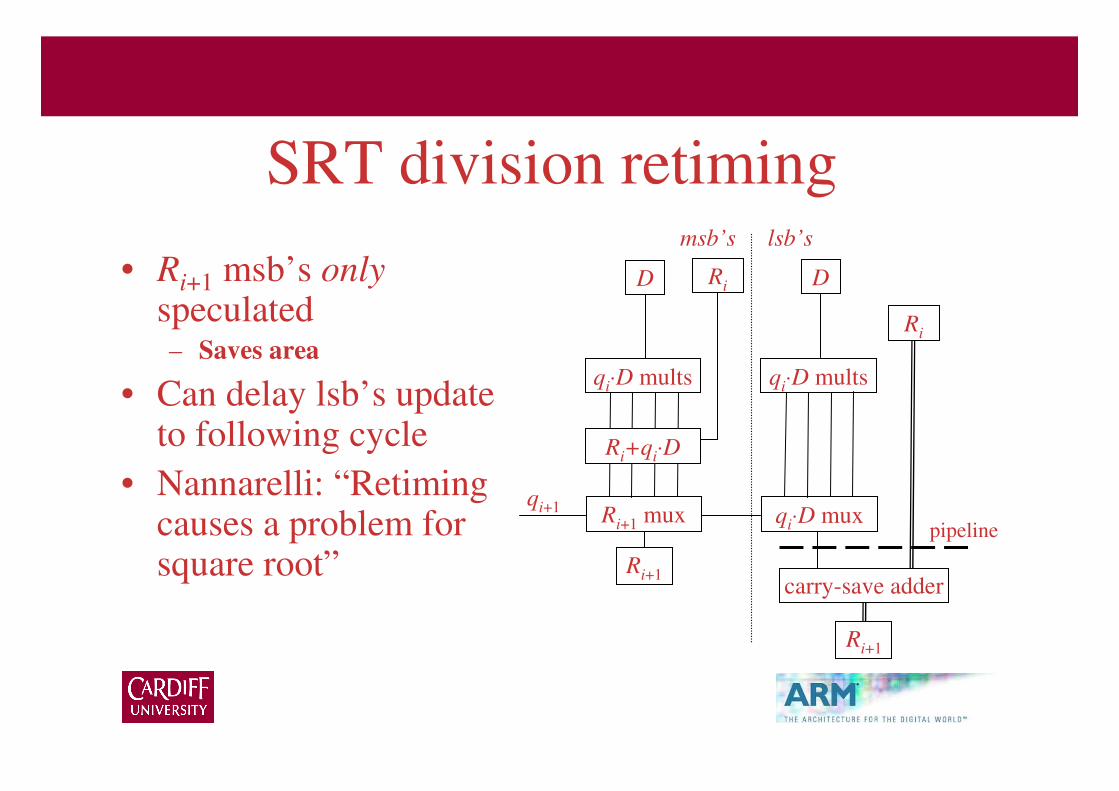
SRT division retiming
• Ri+1 msb’s onlyspeculated– Saves area
• Can delay lsb’s update to following cycle
• Nannarelli: “Retiming causes a problem for square root”
Ri
Ri+1
D
carry-save adder
Ri+1 muxqi+1
Ri+qi⋅D
qi⋅D mults
qi⋅D mux
qi⋅D mults
msb’s lsb’s
pipeline
Ri+1
Ri D

Square root problem
• Ri+1 update depends on qi+1 and msb’s of Qi
– Qi also depends on qi+1
• qi+1 selection depends on msb’s of Ri
• Have to calculate Qi from qi+1 from Ri
before updating Ri+1
– After first few cycles, msb’s of Qi don’t change and
lose dependency between Ri+1 and Qi
Future possibilities?
• Big area reduction possible from retiming, but requires msb’s of Fk (i.e. Qi) to be constant
• Could predict msb’s of Qi from radicand– Does recurrence still work??
• Do radix-2 iterations (i.e. take 2 cycles per iteration Ri → Qi → Ri → Qi etc) until enough msb’s of Ri available to ensure msb’s of Qi are constant between iterations

Summary
• Described design of new high-speed SRT radix-4 combined divide/square root unit– Fast enough & faster than rival publications, but
rather large
– Patent now published, so able to present this work
• Motivated use of Logical Effort– Good for comparisons; not a replacement for TA
– Transparent & repeatable analysis