Embed Size (px)
Citation preview

O + P »Ölhydraulik und Pneumatik« 53 (2009) Nr. 5 1
D e s i g n o f t h e S e l f e n e r g i s i n g E l e c t r o -H y d r a u l i c B r a k e ( S E H B )
Dipl.-Ing. Julian Ewald, Dr.-Ing. Matthias Liermann, Univ.-Prof. Dr.-Ing. H. Murrenhoff Institute for Fluid Power Drives and Controls of RWTH Aachen University
The Self energising Electro-Hydraulic Brake is characterised by a robustdesign, low energy consumption and the possibility of a brake torque con-trol. Therefore it can be used in a broad range of applications.
O + P »Ölhydraulik und Pneumatik« 53 (2009) Nr. 5 2
1 Introduction
The Self energising Electro-Hydraulic Brake (SEHB) is developed at the Institute for Fluid Power Drives and Controls of RWTH Aachen University. The idea was developed during the research project “Intelligent, Integrated Single-Wheel Traction and Brake Module (EABM) /Her08/ and was awarded with the science award of North Rhine-Westphalia /AN07/. In spite of it being originally designed for use in railway vehicles it is also ade-quate for motor vehicles and industrial applications. This article presents the basics about the dimensioning and design of the SEHB. It also shows the conflicts due to contradictory optimisation aims and how they can be solved by compromises. Moreover, a test facility and test results are presented.
1.1 Hydraulic Brakes
Until the 1930s, in some vehicles even until the 1960s, mechanical brakes were used. Bowden cables, leverages and redirections transferred the force from the brake pedal to the wheel brakes. A disadvantage was the high amount of maintenance. Furthermore the ir-regular force transmission to the brake callipers caused uneven wear /Bre04/. The first hy-draulic wheel brake actuator was patented in 1917 by Malcolm Loughead, a civil engineer. This invention started the triumph of hydraulic brakes as it doubled the brakes’ efficiency. In the beginning drum brakes represented the state of the art. Their main advantage is the capability of implementing a mechanical boosting of the brake force. Consequently the activating force can be kept on a low level.
The drum brake has disadvantages because of insufficient cooling, and other disadvantages such as difficult dosability, friction variation and squeaking sounds. When higher brake power was needed, the use of disc brakes became common. However, in the beginning disc brakes with a booster were not available. The necessary actuating force for disk brakes was very high compared to drum brakes. Not until the invention of the pneumatic brake booster, disc brakes succeeded on the market. The vacuum reinforcement provided for high brake power, easy dosability and a low pedal force. A central brake booster between brake pedal and main brake cylinder replaced the local intensification at each drum brake. Dif-ferent reinforcement factors at the wheel brakes were prevented, allowing an equal distri-bution of brake forces. Soon ideas for self energising disc brakes were developed /Tou64/, but they could not compete with brake booster systems.

O + P »Ölhydraulik und Pneumatik« 53 (2009) Nr. 5 3
1.2 Mechatronical Brake Systems
The requirements for brake systems of motor and railway vehicles are becoming more dif-ficult to fulfil. For both types of vehicles high brake power, low energy demand, good con-trollability and the ability of brake force feedback are requested. In addition, there are spe-cific requirements such as a flexible brake management or a distributed brake system with interfaces for railway applications. Pneumatic brake systems or brake systems with vac-uum boosters cannot meet these requirements or can only fulfil them with high effort. This is why the development of mechatronical brake systems is promoted. The wedge brake is an example for a highly developed brake system that works in the region of critical self energisation. The central element of the wedge brake is the wedge bearing. It is located between the moving brake pad and the brake calliper. It allows for the conversion from friction force to clamping force. A control unit influences the position of the wedge by an electric motor with a spindle system /Gom06/.
1.3 Working principle of the SEHB
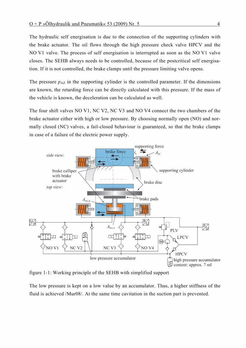
The principal idea of a self energising brake is to use the kinetic energy of the vehicle to clamp the brake shoes towards the brake disk. The brake calliper is moveable in the direc-tion of the friction force. The brake torque is supported by an hydraulic cylinder. In con-trast to other existing brake systems, the SEHB is controlled in the postcritical reinforce-ment region /Lie08/. Depending on the driving direction one of the two supporting cylin-ders is pressed in. figure 1-1 shows the SEHB in top and side view.
The functionality of the SEHB will be explained by describing a brake cycle. Initially the brake is released with a gap between the disc and the brake pads. The valves NC V3 and NO V4 are closed, so that a hydraulic force holds back the prestressed spring, integrated into the brake actuator (BA). As soon as the valve NO V4 opens, chamber B of the brake actuator is connected to low pressure. The spring pushes the brake actuator out and oil is drawn through the check valve into chamber A. The spring force presses the brake pads against the brake disc, building up a low friction force. This force is transferred to the ve-hicle by one of the supporting cylinders. The other cylinder stays in its position allowing a pressure build-up in both directly connected cylinders. The configuration with two plunger cylinders is considerably simpler than preceding systems /Lie06/.
O + P »Ölhydraulik und Pneumatik« 53 (2009) Nr. 5 4
The hydraulic self energisation is due to the connection of the supporting cylinders with the brake actuator. The oil flows through the high pressure check valve HPCV and the NO V1 valve. The process of self energisation is interrupted as soon as the NO V1 valve closes. The SEHB always needs to be controlled, because of the postcritical self energisa-tion. If it is not controlled, the brake clamps until the pressure limiting valve opens.
The pressure pAZ in the supporting cylinder is the controlled parameter. If the dimensions are known, the retarding force can be directly calculated with this pressure. If the mass of the vehicle is known, the deceleration can be calculated as well.
The four shift valves NO V1, NC V2, NC V3 and NO V4 connect the two chambers of the brake actuator either with high or low pressure. By choosing normally open (NO) and nor-mally closed (NC) valves, a fail-closed behaviour is guaranteed, so that the brake clamps in case of a failure of the electric power supply.
figure 1-1: Working principle of the SEHB with simplified support
The low pressure is kept on a low value by an accumulator. Thus, a higher stiffness of the fluid is achieved /Mur08/. At the same time cavitation in the suction part is prevented.
O + P »Ölhydraulik und Pneumatik« 53 (2009) Nr. 5 5
The high pressure accumulator is needed to release the SEHB completely against the spring force of the brake actuator. While braking, the accumulator is charged automatically as soon as the pressure in the high pressure part rises above the loading pressure of the ac-cumulator. To release the brake, the accumulator’s volume of a few millilitres is led into chamber B so that the brake opens completely against the spring force. A gap between the disc and the brake pads is set. If the vehicle is parked and the high pressure accumulator is empty, the vehicle has to be started up against a low braking force from the preloaded spring. Another possibility is to release the brake by the pump shown in figure 1-1.
O + P »Ölhydraulik und Pneumatik« 53 (2009) Nr. 5 6
2 Basics of dimensioning and design
In order to dimension the diameter of the brake actuator (BA) and of the supporting cylin-der (SC) the path of self energisation is considered. By choosing the diameters it is ensured that for all friction coefficients which can occur in normal operation, the pressure in the supporting cylinder is always higher than in the brake actuator. Thus, the brake can ener-gise itself when valve NO V1 is open. From this consideration the simplified condition for the relation of the hydraulic surfaces can be deduced, as presented in /Lie06/.
SCABA Aiµ
A ⋅⋅⋅
>2
1, eq. 2-1
If the relation of the surfaces is given, the minimally necessary friction value µmin can be calculated.
ABA
SC
AA
iµ
,min 2
1⋅
⋅= eq. 2-2
Certain effects, which restrain the self energisation have not been considered in this calcu-lation. These effects are: friction, spring forces and flow losses at the valves. Therefore, in the following, eq. 2-1 will be expanded. The used variables are defined in figure 2-1.

O + P »Ölhydraulik und Pneumatik« 53 (2009) Nr. 5 7
figure 2-1: Definition of hydraulic and mechanic variables
The pressure losses at the high pressure check valve, consisting of the opening pressure and of a part depending on the volume flow, are considered together as the pressure ΔpHPCV. The volume flow through the high pressure check valve also flows through the valve NO V1 causing another pressure loss ΔpNOV1. The pressure losses depend on the op-erating point, the surface of the brake actuator ABA,A and on the compliance of the brake calliper.
1, NOVHPCVABASC pppp Δ+Δ+= eq. 2-3
The mechanical force at the supporting cylinder FSC,mech is balanced to the hydraulic force, the friction forces and to the spring force which presses the piston back to its initial posi-tion.
springSCSCSCSCFederSCSChydrSCmechSC FFApFFFF ,friction,,Reib,,, ++⋅=++= eq. 2-4
The force at the supporting cylinder is also balanced to the friction force actuating in the friction radius. The friction force is calculated with the normal force per brake pad FN, the

O + P »Ölhydraulik und Pneumatik« 53 (2009) Nr. 5 8
friction parameter between brake disc and brake pad µ, the number of friction surfaces (2) and the transmission i. Mass forces are neglected. The conduction of the brake force to the supporting force is considered with an efficiency factor.
NSCmechSC FiF ⋅⋅⋅⋅= μη 2, eq. 2-5
The transmission i is defined as the quotient between friction radius and the distance be-tween the centre of the friction radius and the supporting cylinder’s force application point.
SC
B
rr
i = eq. 2-6
The force applied to the brake pad depends on the efficiency of the brake calliper ηBA. The efficiency factor describes the quotient of the normal force at the friction pad and the force at the brake actuator. This force results from the hydraulic force in chamber A and the spring force reduced by friction forces and by the hydraulic force in chamber B. The hy-draulic chamber B can be used for control or can be connected to low pressure by the valve NO V4. In this case, the pressure in chamber B is equal to the low pressure plus a pressure loss at valve NO V4 caused by the flow.
( )springBAfrictionBABBABBAABAABABASCmechSC FFApApiF ,,,,,,, 2 +−⋅−⋅⋅⋅⋅⋅⋅= ημη eq. 2-7
The minimal friction value is calculated by rearranging eq. 2-7 and inserting it into eq. 2-1 for the critical case.
( )springBAfrictionBABBABBAABAABABASC
mechSC
FFApApiF
,,,,,,
,min 2 +−⋅−⋅⋅⋅⋅⋅⋅
=ημη
μ eq. 2-8
To achieve FSC,mech eq. 2-4 and eq. 2-3 are inserted into eq. 2-8. Furthermore it is assumed that chamber B of the brake actuator is connected to low pressure and that the pressure loss at valve NO V4 is known.
( )( )( )springBAfrictionBABBAEOVLPABAABASC
springAZfrictionSCSCSOVHPCVABA
FFAppApiFFAppp
,,,4,,BA
,,1,min 2 +−⋅Δ+−⋅⋅⋅⋅⋅
++⋅Δ+Δ+=
ηημ eq. 2-9

O + P »Ölhydraulik und Pneumatik« 53 (2009) Nr. 5 9
The minimal friction value depends on the operating point which is expressed by the pa-rameter pBA,A in this context. For the dimensioning it is interesting to know the minimal friction coefficient which still allows self energisation. The pressure pBA,A in chamber A adopts values between low pressure and maximum pressure that are known from the re-quirements. To start with an example for the dimensioning of the SEHB the idealised mini-mal friction coefficient is calculated with eq. 2-2. The resulting value is 0.097. For the cal-culation with eq. 2-9 the parameters listed in table 2-1 are needed as well.
efficiency from friction force to supporting force
ηSC 0,95
efficiency of the brake calli-per
ηBA 0,95
spring force of the brake ac-tuator
FBA,spring 3000 N
friction force of the brake actuator
FBA,friction 500 N
area of the brake actuator, chamber A
ABA,A 5026 mm²
area of the brake actuator, chamber B
ABA,B 3063 mm²
area of the supporting cylin-der
ASC 706,9 mm²
spring force of the supporting cylinder
FSC,spring 150 N
friction force of the support-ing cylinder
FSC,friction 50 N / 100 N
transmission from friction force to supporting force
i 0,725
pressure difference at the high pressure check valve
ΔpHPCV 0,2 bar
pressure difference at valve NO V1
ΔpEOV1 0,1 bar
pressure difference at valve NO V4
ΔpEOV4 0,1 bar
low pressure PLP 2,9 bar
table 2-1: Parameters for the dimensioning
O + P »Ölhydraulik und Pneumatik« 53 (2009) Nr. 5 10
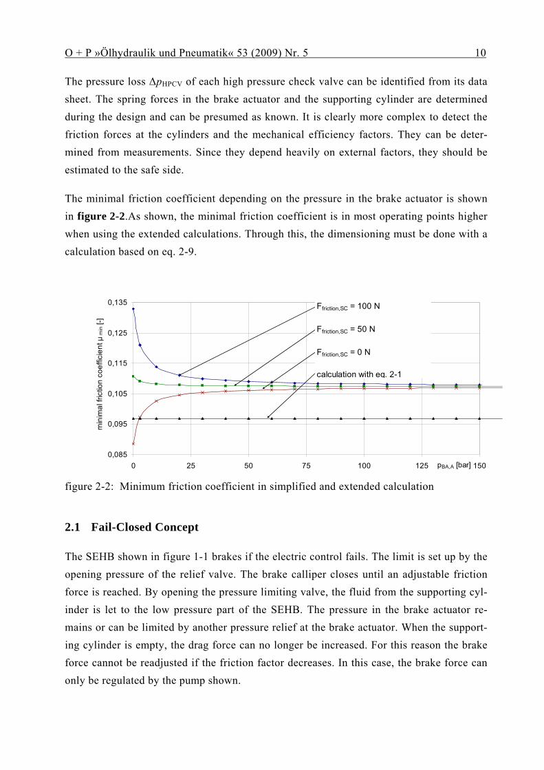
The pressure loss ΔpHPCV of each high pressure check valve can be identified from its data sheet. The spring forces in the brake actuator and the supporting cylinder are determined during the design and can be presumed as known. It is clearly more complex to detect the friction forces at the cylinders and the mechanical efficiency factors. They can be deter-mined from measurements. Since they depend heavily on external factors, they should be estimated to the safe side.
The minimal friction coefficient depending on the pressure in the brake actuator is shown in figure 2-2.As shown, the minimal friction coefficient is in most operating points higher when using the extended calculations. Through this, the dimensioning must be done with a calculation based on eq. 2-9.
0,085
0,095
0,105
0,115
0,125
0,135
0 25 50 75 100 125 150pBA,A [bar]
min
imal
fric
tion
coef
ficie
nt μ
min [-
]
Ffriction,SC = 100 N
Ffriction,SC = 50 N
Ffriction,SC = 0 N
calculation with eq. 2-1
figure 2-2: Minimum friction coefficient in simplified and extended calculation
2.1 Fail-Closed Concept
The SEHB shown in figure 1-1 brakes if the electric control fails. The limit is set up by the opening pressure of the relief valve. The brake calliper closes until an adjustable friction force is reached. By opening the pressure limiting valve, the fluid from the supporting cyl-inder is let to the low pressure part of the SEHB. The pressure in the brake actuator re-mains or can be limited by another pressure relief at the brake actuator. When the support-ing cylinder is empty, the drag force can no longer be increased. For this reason the brake force cannot be readjusted if the friction factor decreases. In this case, the brake force can only be regulated by the pump shown.

O + P »Ölhydraulik und Pneumatik« 53 (2009) Nr. 5 11
Because of the targeted railway application the SEHB incorporates a fail-closed principle. This means that in case of a failure of the power supply it has to brake with a defined brake force. The high force level is achieved by the self energisation. The initialisation of the braking process can be implemented in different ways. Apart from a mechanical spring, a hydraulic force can be considered. figure 2-3 shows three other possibilities for the im-plementation. As an alternative for the spring a hydraulic reservoir could be used. It either actuates the brake directly (1), activates it through an electrically operated valve (2) or ac-tuates a second cylinder (3). The advantage of the hydraulic solution is that it can easily be switched off by a valve. In addition, the hydro accumulator can be positioned separately from the brake actuator to fit into the package. This allows for a very compact brake actua-tor. All variants have in common that they form a system which is hydraulically separated. No connections between the brakes are necessary, the SEHB can be installed as a module without any exterior hydraulic connections. For service issues the SEHB can be maintained when taken off the vehicle.
figure 2-3: Possibilities for the hydraulic “spring”-force
Another possibility to start the braking process is to use a pump as shown in figure 1-1. In this case the pump would have to start for every braking process. As an alternative the use of a(n) (electric) magnet is possible /Hof07/. However, these alternatives require a safe energy supply.
2.2 Fail-Open Concept
In contrast to the fail-closed concept there is the fail-open-concept. It is used in other ap-plications, such as passenger cars. If the control unit fails, there must not be a brake inter-vention as a suddenly blocked wheel can mean a higher risk than the partial fail like of the braking system.

O + P »Ölhydraulik und Pneumatik« 53 (2009) Nr. 5 12
For a fail-open-concept, an unintentional closing of the brake must be prevented. If the electric control fails, any self energisation of the brake must be prohibited. This is why the normally open and the normally closed valves are used interchanged compared to the fail-closed system. In case of a failure in the electric control, the brake actuator is connected with the low pressure. Consequently, the closed brake is released if the electric control fails.
For a fail-open application the brake calliper is significantly simplified because, as in con-ventional automobile brakes, plunger cylinders can be used as actuators. Instead of provid-ing a calliper independent fallback for the actuator, a direct hydraulic connection to the master brake cylinder can be created, in analogy to automobile brakes when the vacuum booster has failed. Experience shows that this connection can be configured so that the safety requirements are met. figure 2-4 shows a breaking system with four SEHB callipers. Still, they are directly connected to a brake pedal. As in conventional brake callipers the brake release is passive. The elastic deformation of the seals serves for an automatic set up of a gap between brake disc and brake pads.
figure 2-4: SEHB for automobile applications with fail-open concept
O + P »Ölhydraulik und Pneumatik« 53 (2009) Nr. 5 13
If the driver wants to decelerate the vehicle, he initiates the brake with the pedal. Addition-ally, the concept provides for a pump so that the SEHB can brake independently from the driver. This is for example needed for the stability program or a driver assistance system. The pressure is led to the brake callipers which are connected to the pedal or the pump by the normally open separation valve (TV). Consequently, the brake pads are pushed towards the brake discs. As soon as a pressure slope is measured, the separation valve TV closes and the valve VV opens, enabling the self energisation. The pressure at the supporting cyl-inder is controlled so that the SEHB features a brake torque control in closed loop opera-tion. The demanded deceleration is deduced from the measured pressure value at the brake pedal or set by a control device.
The brake pedal is connected to the reservoir and to the pump by two valves. If a brake process is initiated by the control unit and the pump, effects on the brake pedal are sup-pressed. In addition, because of the two valves, a pedal simulator can be easily imple-mented. For this purpose, compliance at the brake pedal has to be provided in the form of a small accumulator.
If there is a long ABS braking on fast changing surfaces the oil from the supporting cylin-der is used up. In this case the brake control unit closes the brake calliper further by actuat-ing the pump, as in a conventional electro-hydraulic brake.
2.3 Conflicts of aims
The requirements a brake system must satisfy can be summarized in five categories: forces and dynamics, security, package and weight, comfort and costs. In this chapter contradic-tions are discussed which arise from the optimisation.
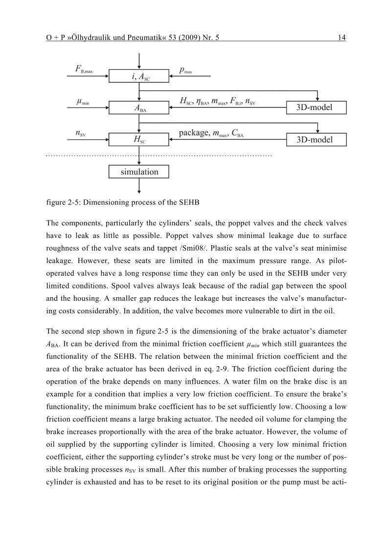
The central requirement is to guarantee a specified stopping distance. For this purpose, the brake is defined. Due to the braking principle, the highest pressure in the supporting cylin-der occurs at the maximum brake force. As the maximum system pressure is limited by the system components, the area of the supporting cylinder and the transmission ratio i are dimensioned first. This first step is shown in top position of figure 2-5. The transmission ratio describes the ratio between friction force and supporting force. It results from the system configuration and especially from the arrangement of the supporting cylinder. The area of the supporting cylinder is then set by the cylinder’s force and by the allowed pres-sure.
O + P »Ölhydraulik und Pneumatik« 53 (2009) Nr. 5 14
figure 2-5: Dimensioning process of the SEHB
The components, particularly the cylinders’ seals, the poppet valves and the check valves have to leak as little as possible. Poppet valves show minimal leakage due to surface roughness of the valve seats and tappet /Smi08/. Plastic seals at the valve’s seat minimise leakage. However, these seats are limited in the maximum pressure range. As pilot-operated valves have a long response time they can only be used in the SEHB under very limited conditions. Spool valves always leak because of the radial gap between the spool and the housing. A smaller gap reduces the leakage but increases the valve’s manufactur-ing costs considerably. In addition, the valve becomes more vulnerable to dirt in the oil.
The second step shown in figure 2-5 is the dimensioning of the brake actuator’s diameter ABA. It can be derived from the minimal friction coefficient µmin which still guarantees the functionality of the SEHB. The relation between the minimal friction coefficient and the area of the brake actuator has been derived in eq. 2-9. The friction coefficient during the operation of the brake depends on many influences. A water film on the brake disc is an example for a condition that implies a very low friction coefficient. To ensure the brake’s functionality, the minimum brake coefficient has to be set sufficiently low. Choosing a low friction coefficient means a large braking actuator. The needed oil volume for clamping the brake increases proportionally with the area of the brake actuator. However, the volume of oil supplied by the supporting cylinder is limited. Choosing a very low minimal friction coefficient, either the supporting cylinder’s stroke must be very long or the number of pos-sible braking processes nSV is small. After this number of braking processes the supporting cylinder is exhausted and has to be reset to its original position or the pump must be acti-

O + P »Ölhydraulik und Pneumatik« 53 (2009) Nr. 5 15
vated. The supporting cylinder’s stroke is mainly restricted by the available package and the allowed weight. As the brake calliper has to follow the stroke of the supporting cylin-der, the needed space matches the traversed envelope. The SEHB’s weight has to be par-ticularly small if the brake calliper has to be added to the unsuspended mass, e.g. in pas-senger cars. In railway vehicles the brake callipers are attached to the bogie which is lo-cated behind the primary suspension. In this case a compromise has to be found, which, on the one hand guarantees the functionality at very low friction coefficients and on the other hand does not unnecessarily increase the package and the weight.
When dimensioning the supporting cylinder’s stroke, the third step, further restrictions have to be considered in addition to limits of the package. First of all, to calculate the needed oil volume for clamping the brake, the stiffness of the brake calliper CBA, including the brake pads and the brake disc, is decisive. During the supporting cylinder’s stroke the radiuses’ ratio of supporting force and brake force can change. This deviation also has to be considered when the minimal friction coefficient is set. If the directions of the support-ing force and brake force vectors change, the allowed shear force at the supporting cylinder must be taken into consideration. figure 2-6 shows a solution to combine a small package with a long stroke of the supporting cylinder. The curved path prevents that the brake cal-liper exceeds the brake disc significantly. The straight parts of the path are fitted to the supporting cylinder so that the shear force is minimal.

O + P »Ölhydraulik und Pneumatik« 53 (2009) Nr. 5 16
figure 2-6: Non-linear support
The minimal friction coefficient also influences the choice of the valves. When the friction coefficient is low, the valve needs a large flow area. Near the minimal friction coefficient the pressure difference at the valve is small. At the same time the brake calliper needs its maximum clamping force for deceleration. Additionally, because of the small stiffness, more compression oil is needed. In contrast, at high friction coefficients a high pressure difference at the valve occurs. A small volume flow at high pressure differences is desir-able to allow a constant dynamic of the brake /Lie08/. This requirement can be fulfilled by proportionally operating valves or by using a flow control valve.
Another possibility to influence the dynamic at different operating points, is to change the working areas at the cylinders. For this purpose a brake actuator can be built up from sev-eral cylinders. The cyclic self energisation of the SEHB can be adjusted in steps if the brake is controlled adequately /Hof07/.
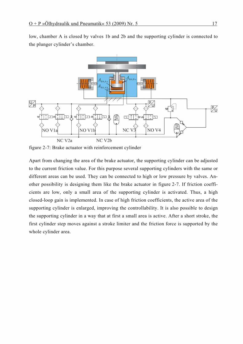
This idea can also be implemented in another way. figure 2-7 shows a brake actuator con-sisting of a differential cylinder whose cylinder housing forms the piston of a plunger cyl-inder which is pushed in by a spring. When the brake is released the spring presses the cyl-inder housing to the inner stroke limit. The differential cylinder is hold back against the spring because of a pressurised chamber B. At high friction coefficients the cylinder hous-ing stays in this position and only the differential cylinder is active. If friction values are
O + P »Ölhydraulik und Pneumatik« 53 (2009) Nr. 5 17
low, chamber A is closed by valves 1b and 2b and the supporting cylinder is connected to the plunger cylinder’s chamber.
figure 2-7: Brake actuator with reinforcement cylinder
Apart from changing the area of the brake actuator, the supporting cylinder can be adjusted to the current friction value. For this purpose several supporting cylinders with the same or different areas can be used. They can be connected to high or low pressure by valves. An-other possibility is designing them like the brake actuator in figure 2-7. If friction coeffi-cients are low, only a small area of the supporting cylinder is activated. Thus, a high closed-loop gain is implemented. In case of high friction coefficients, the active area of the supporting cylinder is enlarged, improving the controllability. It is also possible to design the supporting cylinder in a way that at first a small area is active. After a short stroke, the first cylinder step moves against a stroke limiter and the friction force is supported by the whole cylinder area.

O + P »Ölhydraulik und Pneumatik« 53 (2009) Nr. 5 18
3 SEHB prototype
figure 3-1 shows the prototype built up at the IFAS. The brake calliper is a floating calli-per with a differential cylinder as brake actuator. It rides on guide bolts. A purchased block cylinder is used as the clamping cylinder. On its backside, depicted on the left side of figure 3-1, the valve block is directly flanged. On the front side of the cylinder a tensioned spring is installed in axial direction to provide for the fail-closed behaviour.
figure 3-1: Brake actuator of the SEHB prototype
A pivot bearing connects the floating calliper to the machine bed. The rotating axis is co-axial to the rotating axis of the brake disk. Due to this fact, the brake pad is directed on the brake disc with a constant friction radius. Contrarily to the brake principle shown in figure 1-1, the supporting cylinder is designed as a double rod cylinder. Thus, a standard hydraulic cylinder is used. The spring reset is not integrated into the cylinder, it is mounted to one side of the cylinder. The resulting demand for more construction space is accepted for the prototype. Both chambers of the cylinder are connected to the valve block by hoses.
.

O + P »Ölhydraulik und Pneumatik« 53 (2009) Nr. 5 19
The high and the low pressure accumulators are connected to the valve block by hoses, too. They are mounted onto the machine bed next to the brake. A piston accumulator with a volume of about 7 ml is used as the high pressure accumulator. The volume of the low pressure accumulator is much larger due to the necessary compensation of wear resulting in the brake actuator’s stroke.
The prototype is mounted in the institute’s test field as shown in figure 3-2. It is driven by a flywheel powered by a hydraulic motor, shown on the right side of figure 3-2. The fric-tion force is controlled by a real-time rapid prototype control processor. The test stand software includes maps that compensate the valves’ pressure-dependant behaviour allow-ing for a delicate brake force control. The calculated control signal for the valves is the current in the valves’ solenoids
figure 3-2: Prototype on machine bed
3.1 Valve unit
The valve unit consists of a connection block which is directly screwed on the brake actua-tor and of the valve block itself. The connection block is manufactured from steel. It in-cludes the check valves as well as the connections of the hydraulic lines to the accumula-tors and to the supporting cylinder. In addition, the pressure sensors are installed onto the connection block.

O + P »Ölhydraulik und Pneumatik« 53 (2009) Nr. 5 20
The solenoid valves depicted in figure 1-1 are fit into the valve block. To control the flow at the valve unit in a broad range, the valves are doubled. 2/2-way valves from an automo-tive brake application are used. These valves feature a low price, low leakage, high dynam-ics and a small need of package. The valves are fitted into the valve block as shown in figure 3-3. When pressed into the block, the valves’ housing seals by a knife edge.
figure 3-3: valve block
Since a double rod cylinder is used, an additional valve is necessary. It connects the two chambers of the supporting cylinder to reset it to its original position. This valve function is included in a small valve block which is mounted on the connection block, too. As reset valves, two more normally closed valves are installed back to back. This arrangement is necessary because the normally closed valves open in one direction like check valves. figure 3-3 shows both valves with attached solenoid.
.

O + P »Ölhydraulik und Pneumatik« 53 (2009) Nr. 5 21
4 Measurement results
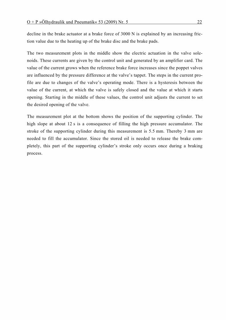
In the last chapter a measurement is exemplarily presented and analysed. figure 4-1 shows a measurement during which the brake force is varied between two levels in the form of a ramp /Ewa08/. The upper measurement plot shows the reference brake force and the actual brake force calculated from the pressure sensor at the supporting cylinder.
time [s]
0
1000
2000
3000
F B [N
]
setpoint valuemeasured value
00.25
0.50.75
11.25
arm
atur
e cu
rren
t [A
]
INCV2
10 12.5 15 17.5 20-46
-44
-42
-40
-38
posi
tion
[mm
]
sSC
01020304050
p [b
ar]
pSC
pBA,A
00.25
0.50.75
11.25
arm
atur
e cu
rren
t [A
]
INOV1
figure 4-1: measurement results /Ewa08/
In the second plot the pressure values in the brake actuator and in the supporting cylinder are shown. The pressure in the supporting cylinder is directly proportional to the braking force. Therefore it is constant when the braking force does not change. The slight pressure
O + P »Ölhydraulik und Pneumatik« 53 (2009) Nr. 5 22
decline in the brake actuator at a brake force of 3000 N is explained by an increasing fric-tion value due to the heating up of the brake disc and the brake pads.
The two measurement plots in the middle show the electric actuation in the valve sole-noids. These currents are given by the control unit and generated by an amplifier card. The value of the current grows when the reference brake force increases since the poppet valves are influenced by the pressure difference at the valve’s tappet. The steps in the current pro-file are due to changes of the valve’s operating mode. There is a hysteresis between the value of the current, at which the valve is safely closed and the value at which it starts opening. Starting in the middle of these values, the control unit adjusts the current to set the desired opening of the valve.
The measurement plot at the bottom shows the position of the supporting cylinder. The high slope at about 12 s is a consequence of filling the high pressure accumulator. The stroke of the supporting cylinder during this measurement is 5.5 mm. Thereby 3 mm are needed to fill the accumulator. Since the stored oil is needed to release the brake com-pletely, this part of the supporting cylinder’s stroke only occurs once during a braking process.

O + P »Ölhydraulik und Pneumatik« 51 (2007) Nr. 1 23
5 Summary and Perspective
The presented dimensioning of the SEHB provides a good insight to the mechatronical sys-tem of the SEHB. The dimensioning requires that all parameters are considered carefully which influence the self energisation. The examination of the SEHB at low friction coeffi-cients is indispensable to guarantee the functionality of the SEHB in all situations.
The presented prototype demonstrates the functionality of the SEHB. In further develop-ment steps the characteristics of the reinforcement can be examined with the prototype. A simulation model can be calibrated to measurements at different operating points. The veri-fied simulation model allows realistic conclusions about dynamic characteristics and con-trollability. In a static dimensioning this is only possible in terms of quality.
The SEHB can be built in different system configurations. Therefore it is appropriate for applications in different environments with different requirements and security concepts. In this article a fail-closed security concept is presented, which meets the security concept of railway vehicles. The SEHB for automobile applications pursues a fail-open security concept. It also includes a fall back level with a direct hydraulic connection between the-brake pedal and the wheel brakes.

O + P »Ölhydraulik und Pneumatik« 46 (2002) Nr. 4 24
6 Bibliography
/AN07/ --- „Aachener bremsen besser“, Aachener Nachrichten, 08.05.2007
/Bre04/ Breuer, Bert; Bill, Karlheinz H.
„Bremsenhandbuch – Grundlagen, Komponenten, Systeme, Fahrdynamik“; 2. edition 2004, Vieweg Verlag
/Ewa08/ Ewald, Julian; Liermann, Matthias; Stammen, Christian; Murrenhoff, Hubertus
„Application of proportional seat valves to a self-energising electro-hydraulic brake”, in: Fluid power and motion control: (FPMC 2008), Bath, GB, Centre for Power Transmission and Motion Control
/Gom06/ Gombert, Bernd; Gutenberg, Philipp
„Die elektronische Keilbremse – Meilensteine auf dem Weg zum elektronischen Radantrieb“, in ATZ, 108(11), 2006
/Her08/ Hermanns, Marcel; Hennen, Martin; Liermann, Matthias; Stützle, Thorsten
„Intelligentes, integriertes Einzelrad-Antriebs-Brems-Modul (EABM)“, in: Eisenbahntechnische Rundschau. Hamburg : DVV Media Group, Eurailpress. - 57 (2008)
/Hof07/ Hofmann, Dirk; Baumann, Dietmar
Disk brake, patent DE102007016250A1, 04.04.2007
/Lie06/ Liermann, Matthias; Stammen, Christian
„Selbstverstärkende hydraulische Bremse für Schienenfahrzeuge: Intelligentes, Integriertes Einzelrad-Antriebs-Brems-Modul“, in: O + P Nr. 50 2006)
/Lie08/ Liermann, Matthias „Self-engergizing Electro-Hydraulic Brake”, dissertation, 2008, Shaker Verlag
/Mur08/ Murrenhoff, Hubertus
„Servohydraulik – Geregelte hydraulische Antriebe“, Shaker Verlag 2008
/Smi08/ Schmidt, Matthias; Murrenhoff, Hubertus; Lohrberg, Henrik; Körber, Franz-Josef
“Influencing parameters on tightness of hydraulic seat valves”, in: Fluid power and motion control: (FPMC 2008), Bath, GB, Centre for Power Transmission and Motion Control
/Tou64/ Tournier, Yves; Henri, Beauchamp
Disk brake, patent FR19630941849, 18. Juli 1963