Embed Size (px)
Citation preview
Design Optimization of Can Type Combustor
T J Prasanna Kumara*, S Koteswara Raob,
S Durga Prasadb1, Md Faisalb2, P Anilb3 a* AE Dept.,PVPSIT, Vijayawada,, Indiab
AE Dept.,PVPSIT, Vijayawada,, India
Abstract - The combustor in a gas turbine is to add energy to the
system to power the turbines, and produce high velocity gas to
exhaust through the nozzle in aircraft applications. Combustion
chambers must be designed to ensure stable combustion of the
fuel injected and optimum fuel utilization within the limited
space available and over a large range of air/fuel ratios. In a gas
turbine engine, the combustor is fed by high pressure air by the
compression system. A combustor must contain and maintain
stable combustion despite very high air flow rates. To do so
combustors are carefully designed to first mix and ignite the air
and fuel, and then mix in more air to complete the combustion
process.
The design of Can-type combustion chamber,
modified can -type combustion chamber geometry and
numerical investigations is carried out. The k-ω model used for
analysis and also the mean temperature, reaction rate, and
velocity fields are almost insensitive to the grid size. Numerical
investigation on Can-type combustion chamber and a modified
can -type combustion chamber geometry is gives less NOx
emission as the temperature at the exit of combustion chamber
is less. For methane as fuel and with initial atmospheric
conditions, the theoretical flame temperature produced by the
flame with a fast combustion reaction is 1950 K. The predicted
maximum flame temperature is 1850 K of the combustion
products compares well with the theoretical adiabatic flame
temperature. Temperature profiles shows increment at
reaction zone due to burning of air-methane mixture and
decrement in temperature downstream of dilution holes
because more and more air will enter in combustion chamber to
dilute the combustion mixture along center line . Specie namely
NOx is increasing and achieving peak point at reaction zone
because they are products of combustion along center line. Due
to increase in equivalence ratio, temperature and mass fraction
of NOx increases because more fuel is utilized. There in not
much variation in temperature and NOx emission by shifting
the axial location of dilution holes. In modified can -type
combustion chamber geometry Temperature profiles shows
increment at reaction zone along the axis due to burning of air-
methane mixture and decrement in temperature downstream
the walls. In modified can-type combustion chamber clearly
shows that temperature and pressure profiles decrease and
contribute to cool the chamber walls but the exit velocity profile
contributes for some losses. The streamline wall cooling is
provided by installing the vanes in the combustion chamber at
different position which enables the proper wall cooling for the
design considered.
Keywords: NOx, Combustor, Swirler, CFD
I. INTRODUCTION TO COMBUSTION
Combustion is a chemical process in which a
substance reacts rapidly with oxygen and gives off heat. The
original substance is called the fuel, and the source of
oxygen is called the oxidizer. The fuel can be a solid, liquid,
or gas, although for airplane propulsion the fuel is usually a
liquid. A combustor is a component or area of a gas turbine,
ramjet, or scramjet engine where combustion takes place. It
is also known as a burner, combustion chamber or flame
holder. In a gas turbine engine, the combustor or combustion
chamber is fed high pressure air by the compression system.
The combustor then heats this air at constant pressure. After
heating, air passes from the combustor through the nozzle
guide vanes to the turbine. In the case of a ramjet or scramjet
engines, the air is directly fed to the nozzle.
A combustor must contain and maintain stable
combustion despite very high air flow rates. To do so
combustors are carefully designed to first mix and ignite the
air and fuel, and then mix in more air to complete the
combustion process.
Early gas turbine engines used a single chamber
known as a can type combustor. Today three main
configurations exist: can, annular and cananular (also
referred to as can-annular tubo-annular). Afterburners are
often considered another type of combustor. Combustors
play a crucial role in determining many of an engine's
operating characteristics, such as fuel efficiency, levels of
emissions and transient response (the response to changing
conditions such a fuel flow and air speed).
II. COMBUSTION SECTION
The combustion section contains the combustion
chambers, igniter plugs, and fuel nozzle or fuel injectors. It
is designed to burn a fuel-air mixture and to deliver
combusted gases to the turbine at a temperature not
exceeding the allowable limit at the turbine inlet.
Theoretically, the compressor delivers 100 percent of its air
by volume to the combustion chamber. However, the fuel-air
mixture has a ratio of l5 parts air to 1 part fuel by weight.
Approximately 25 percent of this air is used to attain the
desired fuel-air ratio. The remaining 75 percent is used to
form an air blanket around the burning gases and to dilute
the temperature, which may reach as high as 3500º F, by
approximately one-half. This ensures that the turbine section
will not be destroyed by excessive heat.
The air used for burning is known as primary air; that
used for cording is secondary air. Secondary air is controlled
and directed by holes and louvers in the combustion
chamber liner. Igniter plugs function during starting only;
they are shut off manually or automatically. Combustion is
continuous and self-supporting. After engine shutdown or
failure to start, a pressure-actuated valve automatically
drains any remaining unburned fuel from the combustion
chamber. The most common type used in Army gas turbine
engines is the external annular reverse-flow type. The
primary function of the combustion section is, of course, to
ISSN: 2278-0181http://www.ijert.org
IJERTV5IS110085(This work is licensed under a Creative Commons Attribution 4.0 International License.)
Published by : International Journal of Engineering Research & Technology (IJERT)
Vol. 5 Issue 11, November-2016
66www.ijert.org
bum the fuel-air mixture, thereby adding heat energy to the
air. To do this efficiently, the combustion chamber must —
Provide the means for mixing the fuel and air to
ensure good combustion.
Bum this mixture efficiently.
Cool the hot combustion products to a temperature
which the turbine blades can withstand under
operating conditions.
Deliver the hot gases to the turbine section.
The location of the combustion section is directly between
the compressor and turbine sections. The combustion
chambers are always arranged coaxially with the compressor
and turbine, regardless of type, since the chambers must be
in a through-flow position to function efficiently.
All combustion chambers contain the same basic elements:
Casing
Perforated inner liner.
Fuel injection system.
A fuel drainage system to drain off unburned fuel after
engine shutdown.
A. Case
The case is the outer shell of the combustor, and is
a fairly simple structure. The casing generally requires little
maintenance. The case is protected from thermal loads by
the air flowing in it, so thermal performance is of limited
concern. However, the casing serves as a pressure vessel that
must withstand the difference between the high pressures
inside the combustor and the lower pressure outside. That
mechanical (rather than thermal) load is a driving design
factor in the case.
B. Diffuser
The purpose of the diffuser is to slow the high
speed, highly compressed, air from the compressor to a
velocity optimal for the combustor. Reducing the velocity
results in an unavoidable loss in total pressure, so one of the
design challenges is to limit the loss of pressure as much as
possible. Furthermore, the diffuser must be designed to limit
the flow distortion as much as possible by avoiding flow
effects like boundary layer separation. Like most other gas
turbine engine components, the diffuser is designed to be as
short and light as possible.
C. Liner
The liner contains the combustion process and
introduces the various airflows (intermediate, dilution, and
cooling, see Air flow paths below) into the combustion zone.
The liner must be designed and built to withstand extended
high temperature cycles.
D. Snout
The snout is an extension of the dome (see below)
that acts as an air splitter, separating the primary air from the
secondary air flows (intermediate, dilution, and cooling air;
see Air flow paths section below).
E. Dome / Swirler
The dome and swirler are the part of the
combustor that the primary air (see Air flow paths below)
flows through as it enters the combustion zone. Their role is
to generate turbulence in the flow to rapidly mix the air with
fuel. Early combustors tended to use bluff body domes
(rather than swirlers), which used a simple plate to create
wake turbulence to mix the fuel and air. Most modern
designs, however, are swirl stabilized (use swirlers). The
swirler establishes a local low pressure zone that forces some
of the combustion products to re-circulate, creating the high
turbulence. However, the higher the turbulence, the higher
the pressure loss will be for the combustor, so the dome and
swirler must be carefully designed so as not to generate more
turbulence than is needed to sufficiently mix the fuel and air.
F. Fuel Injector
The fuel injector is responsible for introducing fuel to the
combustion zone and, along with the swirler (above), is
responsible for mixing the fuel and air. There are four
primary types of fuel injectors; pressure-atomizing, air blast,
vaporizing, and premix/pre-vaporizing injectors.
G. Igniter
Most igniters in gas turbine applications are electrical
spark igniters, similar to automotive spark plugs. The igniter
needs to be in the combustion zone where the fuel and air are
already mixed, but it needs to be far enough upstream so that
it is not damaged by the combustion itself. Once the
combustion is initially started by the igniter, it is self-
sustaining and the igniter is no longer used.
III. AIR FLOW PATHS
A. Primary air
This is the main combustion air. It is highly compressed
air from the high pressure compressor (often decelerated via
the diffuser) that is fed through the main channels in the
dome of the combustor and the first set of liner holes. This
air is mixed with fuel, and then combusted.
B. Intermediate air
Intermediate air is the air injected into the
combustion zone through the second set of liner holes
(primary air goes through the first set). This air completes
the reaction processes, cooling the air down and diluting the
high concentrations of carbon monoxide (CO) and hydrogen
(H2).
C. Dilution air
Dilution air is airflow injected through holes in the
liner at the end of the combustion chamber to help cool the
air to before it reaches the turbine stages. The air is carefully
used to produce the uniform temperature profile desired in
the combustor. However, as turbine blade technology
improves, allowing them to withstand higher temperatures,
dilution air is used less, allowing the use of more
combustion air.
D. Cooling air
Cooling air is airflow that is injected through
small holes in the liner to generate a layer (film) of cool air
to protect the liner from the combustion temperatures. The
implementation of cooling air has to be carefully designed so
it does not directly interact with the combustion air and
process. In some cases, as much as 50% of the inlet air is
used as cooling air.
IV. MODELLING
A. Introduction to ANSYS ICEM
Meeting the requirements for integrated mesh
generation and post processing tools for today’s
sophisticated analysis. ANSYS ICEM CFD provides
geometry acquisition, mesh generation, mesh optimization,
and post processing tools.
ISSN: 2278-0181http://www.ijert.org
IJERTV5IS110085(This work is licensed under a Creative Commons Attribution 4.0 International License.)
Published by : International Journal of Engineering Research & Technology (IJERT)
Vol. 5 Issue 11, November-2016
67www.ijert.org
Maintaining a close relationship with the geometry during
mesh generation and post processing, ANSYS ICEM CFD is
used especially in engineering applications such as
computational fluid dynamics and structural analysis.
ANSYS ICEM CFD’s mesh generation tools offer the
capability to parametrically create meshes from in numerous
formats
Multi-block structured
Unstructured hexahedral
Cartesian with h grid refinement
Hybrid Meshes comprising hexahedral, tetrahedral,
pyramidal and/or prismatic elements
Quadrilateral and triangular surface meshing
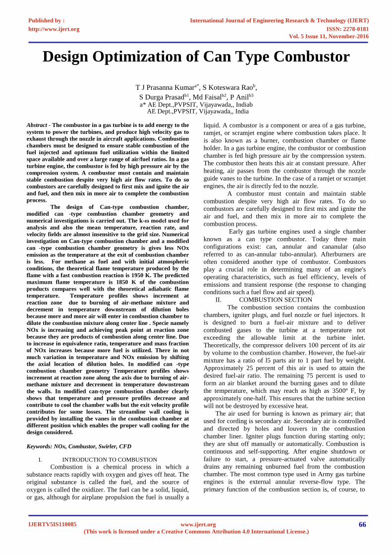
B. DESIGN OF BASIC CAN TYPE COMBUSTION
CHAMBER GEOMENTRY
Figure-1(a): Geometry for Basic Can type
combustion chamber.
Figure-1(b): Complete Design of Basic Can Type
Combustion Chamber.
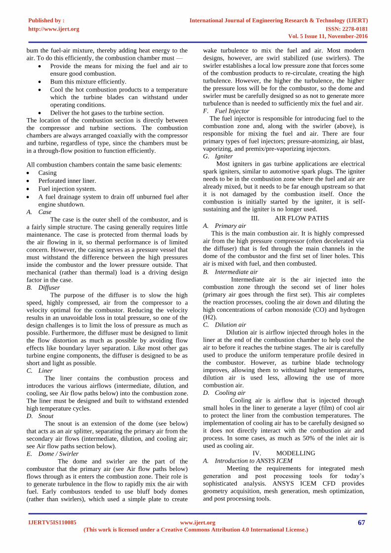
C. DESIGN OF MODIFIED CAN TYPE
COMBUSTION CHAMBER GEOMENTRY
Figure-2(a): Geometry for Modified Can Type Combustion Chamber.
Figure-2(b): Complete Modified Can Type Combustion Chamber Design
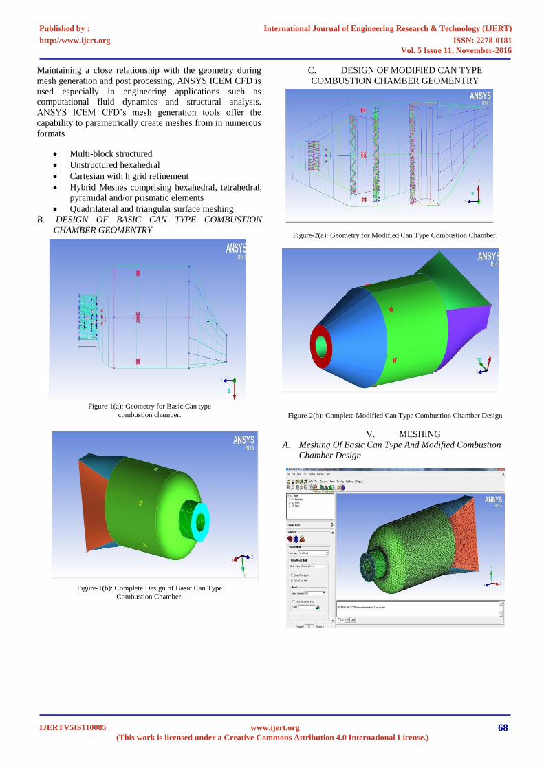
V. MESHING
A. Meshing Of Basic Can Type And Modified Combustion
Chamber Design
ISSN: 2278-0181http://www.ijert.org
IJERTV5IS110085(This work is licensed under a Creative Commons Attribution 4.0 International License.)
Published by : International Journal of Engineering Research & Technology (IJERT)
Vol. 5 Issue 11, November-2016
68www.ijert.org
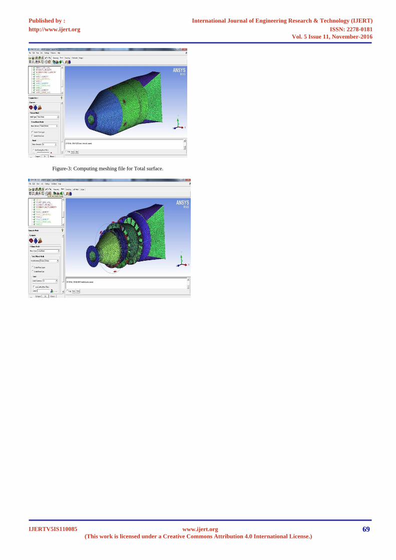
Figure-3: Computing meshing file for Total surface.
ISSN: 2278-0181http://www.ijert.org
IJERTV5IS110085(This work is licensed under a Creative Commons Attribution 4.0 International License.)
Published by : International Journal of Engineering Research & Technology (IJERT)
Vol. 5 Issue 11, November-2016
69www.ijert.org
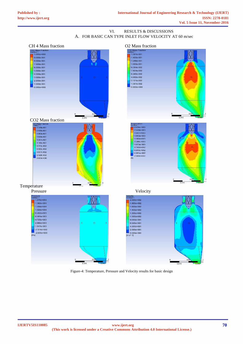
VI. RESULTS & DISCUSSIONS
A. FOR BASIC CAN TYPE INLET FLOW VELOCITY AT 60 m/sec
CH 4 Mass fraction O2 Mass fraction
CO2 Mass fraction
Temperature
Pressure Velocity
Figure-4: Temperature, Pressure and Velocity results for basic design
ISSN: 2278-0181http://www.ijert.org
IJERTV5IS110085(This work is licensed under a Creative Commons Attribution 4.0 International License.)
Published by : International Journal of Engineering Research & Technology (IJERT)
Vol. 5 Issue 11, November-2016
70www.ijert.org
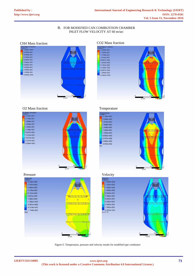
B. FOR MODEFIED CAN COMBUSTION CHAMBER
INLET FLOW VELOCITY AT 60 m/sec
CO2
Mass fraction
CH4 Mass fraction
O2 Mass fraction
Temperature
Pressure
Velocity
Figure-5: Temperature, pressure and velocity results for modified type combustor
ISSN: 2278-0181http://www.ijert.org
IJERTV5IS110085(This work is licensed under a Creative Commons Attribution 4.0 International License.)
Published by : International Journal of Engineering Research & Technology (IJERT)
Vol. 5 Issue 11, November-2016
71www.ijert.org
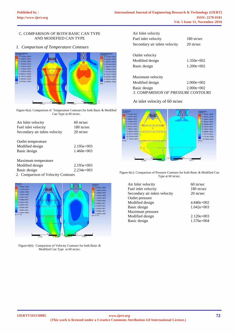
C. COMPARISON OF BOTH BASIC CAN TYPE
AND MODEFIED CAN TYPE
1. Comparison of Temperature Contours
Figure-6(a): Comparison of
Temperature Contours for both Basic & Modified
Can Type at 60 m/sec.
2. Comparison of Velocity Contours
Figure-6(b): Comparison of Velocity Contours for both Basic & Modified Can Type
at 60 m/sec.
3. COMPARISION OF PRESSURE CONTOURS
At inlet velocity of 60 m/sec
Figure-6(c): Comparison of Pressure Contours for both Basic & Modified Can
Type at 60 m/sec.
Air Inlet velocity
60 m/sec
Fuel inlet velocity
180 m/sec
Secondary air inlets velocity
20 m/sec
Outlet pressure
Modified design
4.840e+002
Basic design
1.042e+003
Maximum pressure
Modified design
2.120e+003
Basic design
1.576e+004
Air Inlet velocity
60 m/sec
Fuel inlet velocity
180 m/sec
Secondary air inlets velocity
20 m/sec
Outlet temperature
Modified design
2.195e+003
Basic design
1.460e+003
Maximum temperature
Modified design
2.195e+003
Basic design
2.234e+003
Air Inlet velocity
Fuel inlet velocity
180 m/sec
Secondary air inlets velocity
20 m/sec
Outlet velocity
Modified design
1.350e+002
Basic design
1.200e+002
Maximum velocity
Modified design
2.000e+002
Basic design
2.000e+002
ISSN: 2278-0181http://www.ijert.org
IJERTV5IS110085(This work is licensed under a Creative Commons Attribution 4.0 International License.)
Published by : International Journal of Engineering Research & Technology (IJERT)
Vol. 5 Issue 11, November-2016
72www.ijert.org
VII.
CONCLUSION
The design of Can-type combustion chamber,
modified can -type combustion chamber geometry and
numerical investigations is carried out. The k-ω model
used for analysis and also the mean temperature, reaction
rate, and velocity fields are almost insensitive to the grid
size. Numerical investigation on Can-type combustion
chamber and a modified can -type combustion chamber
geometry is gives less NO emission as the temperature at
the exit of combustion chamber is less. For methane as fuel
and with initial atmospheric conditions, the theoretical
flame temperature produced by the flame with a fast
combustion reaction is 1950 K. The predicted maximum
flame temperature is 1850 K of the combustion products
compares well with the theoretical adiabatic flame
temperature. Temperature profiles shows increment at
reaction zone due to burning of air-methane mixture and
decrement in temperature downstream of dilution holes
because more and more air will enter in combustion
chamber to dilute the combustion mixture along center line
. Specie namely NO is increasing and achieving peak point
at reaction zone because they are products of combustion
along center line. Due to increase in equivalence ratio,
temperature and mass fraction of NO increases because
more fuel is utilized. There in not much variation in
temperature and NO emission by shifting the axial location
of dilution holes. In modified can -type combustion
chamber geometry Temperature profiles shows increment
at reaction zone along the axis due to burning of air-
methane mixture and decrement in temperature
downstream the walls. In modified can -type combustion
chamber clearly shows that temperature and pressure
profiles decrease and contribute to cool the chamber walls
but the exit velocity profile contributes for some losses.
The streamline wall cooling is provided by installing the
vanes in the combustion chamber at different position
which enables the proper wall cooling for the design
considered.
REFERENCES
[1]
V. M. Reddy and S. Kumar, Development of high intensity
low emission combustor for achieving flameless
combustion, Propulsion and Power Research, Vol. 2, 2013,
pp. 139–147.
[2]
C. Ghenai, “Combustion of syngas fuel in gas turbine can
combustor,” Advances in Mechanical Engineering, Vol. 1,
2010, pp. 1-13.
[3]
P. S. Kumar and P. P. Rao, “Design and analysis of gas
turbine combustion chamber," International
Journal of
Computational Engineering Research, Vol. 3, 2012, pp. 1-6.
[4]
H. Pathan, K. Partel, and V. Tadvi, “Numerical investigation
of the combustion of methane air mixture in gas turbine
can-type combustion
chamber,” International Journal of
Scientific & Engineering Research, Vol. 3, No. 10, 2012,
pp. 1-7.
[5]
P. Koutmos and J. J. McGuirk, “Isothermal flow in a gas
turbine combustor–a benchmark experimental study,”
Experiments in Fluids, Vol.7, 1989, pp. 344-354.
[6]
Y. A. Eldrainy, J. Jeffrie, and M. Jaafar, “Prediction of the
flow inside a Micro Gas Turbine Combustor,” Journal of
Mechanical, vol. 25,2008, pp. 50-63.
[7]
J. A. Wunning, and J. G. Wunning, “Flameless oxidation to
reduce thermal NO-formation,” Progress
in Energy and
Combustion Science,Vol. 23, No. 1, 1997, pp. 81– 94.
[8]
B. E. Launder and D. B. Spalding, “The numerical
computation of turbulent flows,” Computer Methods in
Applied Mechanics and Engineering, Vol. 3, 1974, pp. 269-
289.
[9]
M. Y. Kim, “Effect of swirl on gas-fired combustion
behaviour in a 3-D rectangular combustion chamber,”
World Academy of Science,
ISSN: 2278-0181http://www.ijert.org
IJERTV5IS110085(This work is licensed under a Creative Commons Attribution 4.0 International License.)
Published by : International Journal of Engineering Research & Technology (IJERT)
Vol. 5 Issue 11, November-2016
73www.ijert.org