Embed Size (px)
Citation preview

DESIGN OPTIMIZATION STUDY ON THE FORMULA VARSITY CAR
CHASSIS
MUHAMMAD SHUKRI BIN AHMAD AZAZI
UNIVERSITI TEKNIKAL MALAYSIA MELAKA
“I hereby declare that I have read this thesis and my opinion this report is sufficient
in terms of scope and quality for the award of the degree of
Bachelor of Mechanical Engineering (Design & Innovation).”
Signature : ……………………………………....
Supervisor : DR. ABD RAHMAN BIN DULLAH
Date : ……………………………………....

DESIGN OPTIMIZATION STUDY ON THE FORMULA VARSITY CAR
CHASSIS
MUHAMMAD SHUKRI BIN AHMAD AZAZI
This report is presented in
Partial fulfillment of the requirements for the
Degree of Bachelor of Mechanical Engineering (Design & Innovation)
Faculty of Mechanical Engineering
Universiti Teknikal Malaysia Melaka
JUNE 2013
ii
DECLARATION
“I hereby declare that the work in this report is my own except for summaries and
quotations which have been duly acknowledgement.”
Signature : …………………………………………………
Author : MUHAMMAD SHUKRI BIN AHMAD AZAZI
Date : …………………………………………………
iii
DEDICATION
“To my beloved parents Mr. Ahmad Azazi bin Che Hin
and Mrs. Rohani binti Md Nor”
iv
ACKNOWLEDGEMENT
Alhamdullillah, thanks to Allah with it is consent I can finish this report for
successfully. I also would like to thanks to Dr. Abd Rahman Bin Dullah and
appreciative of his guide during the research I do and during prepare this report.
Furthermore, many thanks to my collage friend especially my housemate because
with them encouragement and support I can complete this Final Year Project report.
Without their cooperation it is difficult to me to complete this report. Not forgotten to
my beloved parents and family that always supporting and praying for my successful
to complete my degree study. Finally, I would like to thanks to everyone have
involved directly or indirectly in my research study until I finished this report.
Thank you very much.
JUNE 2013

vi
ABSTRACT
The design of a chassis contains all necessary components to support loads of
the car and the driver. A formula varsity race car chassis have different parts, among
them are chassis base. In this project the goal is to optimize the chassis base using
HyperWorks software. Furthermore, optimization have different methods but in this
project the method are used is topology optimization. Second chapter in this report is
about literature review of competition regulation, chassis design, types of material,
stiffness torsional and optimization method. Then, the methods are used along
conducted this project are shown in the third chapter. These projects basically use
Catia software to develop CAD data and HyperWorks software to do analysis. Only
linear static analysis is conducted in this project to identify the maximum
displacement and maximum von mises stress of the model. The basic idea of this
project is the load prediction come from the weight of the driver which is 1000N and
the constraint at front and rear wheel side. In HyperWorks software, linear static
analysis can only be done in Radioss or OptiStruct. Besides that, OptiStruct also act
as a solver for optimization problem. The objective of optimization in this is
minimum the compliance. After done the optimization process, the way to valid the
optimized design with make comparison between the existing model and optimized
design. Lastly, the percent are obtained from displacement reduction is 52 % and the
von mises stress reduction is 53%.

vii
ABSTRAK
Rekabentuk casis mempunyai semua keperluan dalam menyokong berat
daraipada kereta dan pemandu. Casis kereta lumba formula varsiti mempunyai
berlainan bahagian antaranya ialah tapak casis. Matlamat dalam projek ini adalah
dengan mengoptimumkan tapak casis menggunakan perisian HyperWorks. Selain
itu, pengoptimumnan mempunyai pelbagai cara tetapi di dalam projek ini kaedah
yang di gunakan ialah pengoptimunan secara topology. Tajuk kedua dalam laporan
ini adalah mengenai kajian ilmiah tentang peraturan perlumbaan, rekabentuk casis,
jenis – jenis bahan, kilasan ketegangan dan keadah pengoptiminan. Kemudian,
kaedah yang digunakan sepanjang menjalakan projek ini ditunjukkan di dalam tajuk
ketiga. Pada dasarnya projek ini menggunakan perisian Catia untuk membuat CAD
data dan perisian HyperWorks untuk membuat analisis. Hanya analisis statik linear
di dalam projek ini untuk mengenal pasti maximum anjakan dan maximum tekanan
von mises. Idea asas dalam projek adalah menjangkakan berat yang datang adalah
daripada berat pemandu dan kekangannya datang daripada bahagian depan dan
belakang tayar. Dalam perisian HyperWorks, analisis statik linear dilakukan dalam
Radioss dan Optistruct. Selain itu juga OptiStruct bertindak sebagai penyelesai dalam
masalah pengoptimuman. Objektif pengoptimuman adalah dengan meminimumkan
pelbagai masalah kepada hanya satu masalah sahaja. Selepas menyiapkan
pengoptimuman proses, cara untuk menilai rekabentuk yang telah dioptimumkan
dengan membuat perbandingan antara rekabentuk sedia ada dengan rekabentuk yang
telah dioptimumkan. Akhir sekali, peratus yang diperolehi daripada pengurangan
anjakan adalah 52 % dan pengurangan ketegangan von mises adalah 53%.

viii
CONTENTS
CHAPTER ITEMS PAGE
DECLARATION ii
DEDICATION iii
ACKNOWLEDGEMENT iv
ABSTRACT v
ABSTRAK vi
CONTENTS vii
LIST OF TABLES x
LIST OF FIGURES xi
LIST OF ABBREVIATIONS xiii
LIST OF APPENDIX xiv
CHAPTER 1 INTRODUCTION
1.1 Background 1
1.2 Objective 2
1.3 Problem Statement 2
1.4 Scope 2
CHAPTER 2 LITERATURE REVIEW
2.1 Competition Rule 3
2.2 Types of Chassis Design 5
2.2.1 Ladder Frame 5
2.2.2 Space Frame 5
2.2.3 Backbone Chassis 6
2.2.4 Monocoque 7
2.3 Types of Chassis used in Formula SAE 7

ix
2.3.1 Tubular Steel Space Frame 8
2.3.2 Metal Monocoque 8
2.3.3 Composite Semi Monocoque 9
2.4 Types of Materials 9
2.4.1 Steel 9
2.4.2 Plain Carbon Steel 9
2.4.5 Alloy Steel 10
2.4.6 Stainless Steel 10
2.4.7 Aluminum 10
2.5 Stiffness Torsional 11
2.5.1 Longitudinal Torsion 11
2.5.2 Vertical Bending 12
2.5.3 Lateral Bending 12
2.5.4 Horizontal Lozenging 13
2.6 Optimization Methods 14
2.6.1 Topology Optimization 14
2.6.2 Topometry Optimization 14
2.6.3 Topography Optimization 15
2.6.4 Size Optimization 15
2.6.5 Shape Optimization 15
CHAPTER 3 METHODOLOGY
3.1 Project Flow Chart 16
3.2 Literature Review 18
3.3 Create Existing Design 18
3.4 Generate Idea 19
3.5 Package Space 19
3.6 Analysis and Optimization Method 20
3.1.1 Pre – Processing 21
3.1.2 Solving 21
3.1.3 Post – Processing 21

x
CHAPTER 4 ANALYSIS AND OPTIMIZATION
4.1 Importing CAD Data 23
4.2 Shell Meshing 25
4.3 Linear Static Analysis for Existing Chassis Base 26
4.3.1 Analysis set up 27
4.4 Topology Optimization 33
4.4.1 Package Space 34
4.4.2 Create Mesh and Property 34
4.4.3 Set up the Design Variable 35
4.4.4 Creation of Response 36
4.4.5 Creation of Constraint 37
4.4.6 Define the Objective Function 38
4.4.7 Job Submitted 40
CHAPTER 5 RESULT AND DISCUSSION
5.1 Linear Static Result for Existing Chassis Base 42
5.2 Topology Optimization Result 42
5.3 Linear Static Result for Optimized Chassis Base 44
5.4 Comparison of Result 45
5.5 Discussion 46
5.5.1 To Generate Idea 46
5.5.2 Set up the Optimization Variable 46
5.5.3 Interpretation of the Result 47
5.5.4 Comparison of the Result 47
CHAPTER 6 CONCLUSIONS & RECOMMENDATION
6.1 Conclusion 48
6.2 Recommendation 49
REFERENCES 50
BIBLOGRAPHY 51
APPENDIX A 52
APPENDIX B 56
x
LIST OF TABLES
NO. TITLE PAGE
2.1 Range of plain carbon steel 9
5.1 Linear static analysis result for existing chassis base 42
5.2 Topology optimization result 43
5.3 Result for optimized chassis base 44
5.4 Comparison of maximum displacement result 45
5.5 Comparison of maximum von mises stress result 45

xi
LIST OF FIGURE
NO. TITLE PAGE
2.1 Illustrated of side impact member 4
2.2 Illustrated of helmet clearance 4
2.3 Illustrated of Ladder Frame 5
2.4 Space frame chassis 6
2.5 Example of Backbone Chassis 6
2.6 Example of Monocoque Chassis 7
2.7 Longitudinal Torsion 11
2.8 Vertical Bending 12
2.9 Lateral Bending Deformation Mode 12
2.10 Horizontal Lozenging 13
3.1 Project Flow Chart 17
3.2 3D model of existing formula varsity race car chassis base 18
3.3 Chassis base with force and constraints 19
3.4 Chassis base with package space 20
3.5 Flow chart of workflow in the HyperWorks 22
4.1 Importing icon in the HyperWorks panel 24
4.2 Importing CAD 24
4.3 Existing chassis base CAD data in HyperMesh 24
4.4 Panels in the HyperWorks for create mesh 25
4.5 Existing chassis base after mesh in HyperMesh working view 26
4.6 Material creating panel in HyperWorks 27
4.7 Material card edit panel in HyperWorks 28
4.8 PSHELL card edit panel in HyperWorks 29
4.9 Load collector panel. 29
4.10 Existing chassis base with forces 30
xii
4.11 Constraints panel in HyperWorks 30
4.12 Existing chassis base with constraint 31
4.13 LoadSteps panel in HyperWorks 31
4.14 Model panel in HyperWorks 32
4.15 Analysis panels using Radioss 32
4.16 Package space 34
4.17 Package Space with load and constraints 35
4.18 Panels in HyperWorks to create design variable 36
4.19 Panels in HyperWorks to create responses 37
4.20 Panels in HyperWorks to create constraints 38
4.21 Panels in HyperWorks to define objective 39
4.22 Model Browser 39
4.23 Panels in HyperWorks to submit the job 40
5.1 Result panel in HyperWorks 41
5.2 Displacement and Von Mises Stress for existing chassis base 42
5.3 Firts iteration 43
5.4 Last iteration 43
5.5 Displacement and Von Misses Stress for optimized design 44

xiii
LIST OF ABBREVIATIONS
UTeM = Universiti Teknikal Malaysia Melaka
mm = millimeter
MPa = Mega Pascal
2D = Two Dimension
3D = Three Dimension
CAD = Computer Aided Design
FEA = Finite Element Analysis
FEM = Finite Element Method
Catia = Computer Aided Three Dimension Interactive Application
minmemb = Minimum member size
mindim = Minimum diameter
PSHELL = Shell property
W = Objective function
g = Structural responses
F = Vector of load
k = Stiffness matrix
x = Displacement vector
= Stress
= Strain
E = Elasticity matrix
xiv
LIST OF APPENDIX
NO. TITLE PAGE
A HyperWorks Tools 52
B Technical Drawing 56

1
CHAPTER 1
INTRODUCTION
1.1 BACKGROUND
Formula Varsity is a mini F1 race was introduced by Faculty of Mechanical
Engineering, Universiti Teknikal Malaysia Melaka (UTeM) since 2006. The first
program was organized on 14 September 2006 with sole participation and
subsequently thrive with participation from fives Higher Education Institutions (HEI)
in 2008.
Formula Varsity is a biannual event, and on the third event in October 2010
marked its own record when it succeeded to get 25 teams from various Higher
Education Institutions (HEI) as well as nationwide polytechnics to participate.
However, Formula Varsity 2012 has received 44 requests from the Higher Education
Institutions (HEI) but only 25 teams were selected because of the advice from the
circuit management.
The tournament challenges engineering students to design, build and test their
self-developed formula style racing cars. It is also an event where student can test
their skill and apply the theory that they have learn in class to provides students
become creative problem solving and team working skill.

2
1.2 OBJECTIVE
The purpose of the study is to optimize a chassis base by using HyperWorks
software for UTeM Formula Varsity Race Car.
1.3 PROBLEM STATEMENT
The design of a chassis contains all the necessary components to support the
car and the driver. In order that many areas need to be studied and tested to produce a
competitive vehicle with optimum chassis performance.
The variables that can affect the formula varsity car chassis are the types of
material, the diameter or dimension of tubes use for built space frame chassis and the
design geometry of chassis. In order to optimize the chassis, analysis of the chassis
base will be done on the HyperWorks software.
1.4 SCOPE
i. Literature review on the chassis design, material, structural analysis,
and optimization methods.
ii. To study the previous chassis base and generates idea of optimization
the chassis base.
iii. To follow the finite element method by using HyperWorks.
iv. To optimize the chassis base according topology optimization method
by using OptiStruct.
v. To validate the design by compare the new chassis base design with
the existing chassis base design.

3
CHAPTER II
LITERATURE REVIEW
Here is the review about what are related or will be used in this project. This project
basically related to the formula varsity competition, the race car chassis design, types
of material, stiffness torsional and the optimization methods.
2.1 Competition Rules
Rules intended to give freedom to modify or replace some parts in the
interest of safety, research and development. The rule also intended to provide fair
competitions and maintain parity.
Participants must follow the rules to prevent the removed from the competition if one
small sub-section of chassis rule is not followed. Therefore, to simplify this process a
summary of the rules was created and focus on the primary structure such as main
hoop, front hoop, roll hoop braces and support, side impact structure, front bulkhead,
front bulkhead support and all frame member.
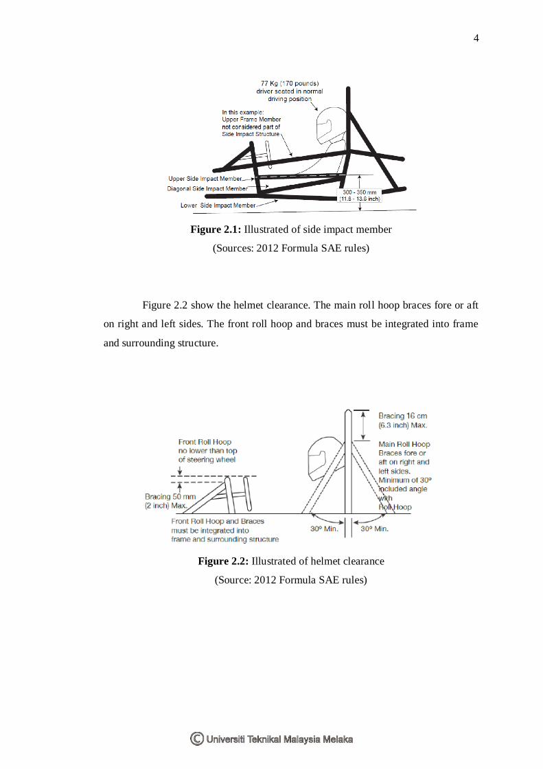
Figure 2.1 show the side impact structure and the normal driving position.
There are three side members in side impact structure, first is upper side impact
member, second is diagonal side impact member and lastly is lower side impact
member. These member are function to protect the driver if had an accident.
4
Figure 2.1: Illustrated of side impact member
(Sources: 2012 Formula SAE rules)
Figure 2.2 show the helmet clearance. The main roll hoop braces fore or aft
on right and left sides. The front roll hoop and braces must be integrated into frame
and surrounding structure.
Figure 2.2: Illustrated of helmet clearance
(Source: 2012 Formula SAE rules)

5
2.2 TYPES OF CHASSIS DESIGN
There are four types of chassis design. In this part will be discuss the four
types of chassis. The discussion is focus on the design in terms of load loading,
material, and the shape. The fact of the design had obtained from the Mr. Wakeham
book.
2.2.1 Ladder Frame
Ladder frame consists of two long beams that run the length of the vehicle
and provide a strong support for weight and originally based on a carriage design.
Body on frame architecture is a good example of this type of chassis. (Wakeham,
2009)
Figure 2.3: Illustrated of Ladder Frame
(Source: http://www.autozine.org/technical_school/chassis/tech_chassis.htm)
2.2.2 Space Frame
Space frame is a nodal triangulated truss network that attempts to distribute
all loads into axial directions so that no part of the frame is subjected to the harsher
bending forces. A good example of this type of chassis is most Formula SAE chassis
or a Lamborgini Countach. (Wakeham, 2009)
6
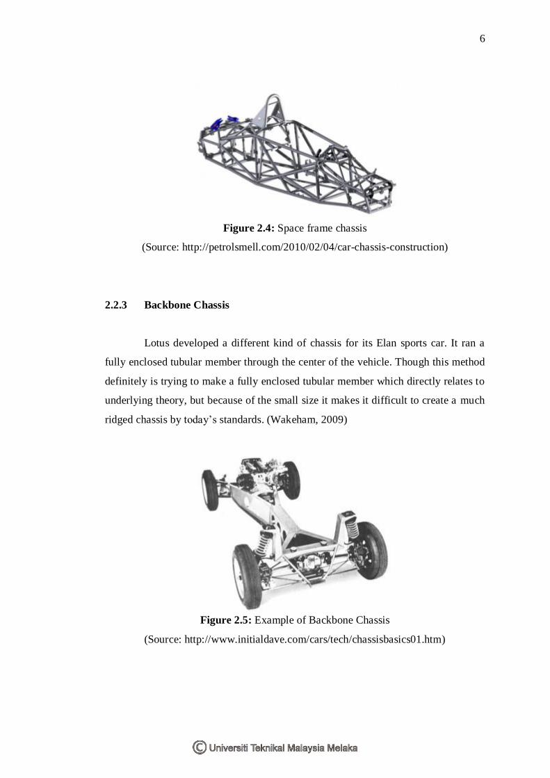
Figure 2.4: Space frame chassis
(Source: http://petrolsmell.com/2010/02/04/car-chassis-construction)
2.2.3 Backbone Chassis
Lotus developed a different kind of chassis for its Elan sports car. It ran a
fully enclosed tubular member through the center of the vehicle. Though this method
definitely is trying to make a fully enclosed tubular member which directly relates to
underlying theory, but because of the small size it makes it difficult to create a much
ridged chassis by today’s standards. (Wakeham, 2009)
Figure 2.5: Example of Backbone Chassis
(Source: http://www.initialdave.com/cars/tech/chassisbasics01.htm)
7
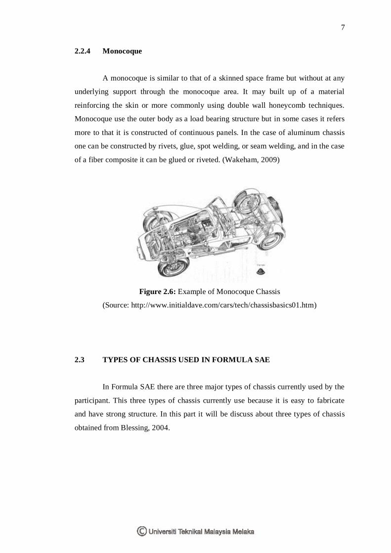
2.2.4 Monocoque
A monocoque is similar to that of a skinned space frame but without at any
underlying support through the monocoque area. It may built up of a material
reinforcing the skin or more commonly using double wall honeycomb techniques.
Monocoque use the outer body as a load bearing structure but in some cases it refers
more to that it is constructed of continuous panels. In the case of aluminum chassis
one can be constructed by rivets, glue, spot welding, or seam welding, and in the case
of a fiber composite it can be glued or riveted. (Wakeham, 2009)
Figure 2.6: Example of Monocoque Chassis
(Source: http://www.initialdave.com/cars/tech/chassisbasics01.htm)
2.3 TYPES OF CHASSIS USED IN FORMULA SAE
In Formula SAE there are three major types of chassis currently used by the
participant. This three types of chassis currently use because it is easy to fabricate
and have strong structure. In this part it will be discuss about three types of chassis
obtained from Blessing, 2004.
8
2.3.1 Tubular Steel Space Frame
Tubular steel space frames are possibly the most popular chassis design in
Formula SAE. Part of the competition process is the validation of your design to the
design judges; the tubular space frame is easiest. As the design judges have only a
limited amount of time to inspect the vehicles, they need to see that the chassis
performs as the claims. As tubular structures are common in motorsports, it is easy
for judges to visually access the design of a space frame. (Blessing, 2004)
2.3.2 Metal Monocoque
Metal Monocoque design can also be easily visually assessed for load paths
and expected forces, as they are usually a tubular space frame with bonded aluminum
panels used to increase stiffness and to act as bodywork. The aluminum sheeting is
only ¼” to ½” thick, but the claimed stiffness increase is significant. Instead of
aluminum, carbon fiber panels can be used to the same effect, which is more
effective for complicated geometry and sections that are out of plane. (Blessing,
2004)
2.3.3 Composite Semi Monocoque
Composite semi monocoque is usually a tub design, with the material used a
carbon fiber matrix with an epoxy resin. There are usually several materials included
in the lay-up process to modify the properties of composite materials available for
chassis construction compared to the known and familiar properties of steel. Because
of this there are significant equivalency rules in place to ensure that the minimum
safety requirements for the chassis are met. (Blessing, 2004)