Embed Size (px)
Citation preview
Design Overview of Design Overview of Shielded ContainersShielded Containers
Brad DayBrad DayJuly 8, 2008July 8, 2008Presentation to the NRCPresentation to the NRC

22
Governing Design Governing Design Requirements/ObjectivesRequirements/Objectives
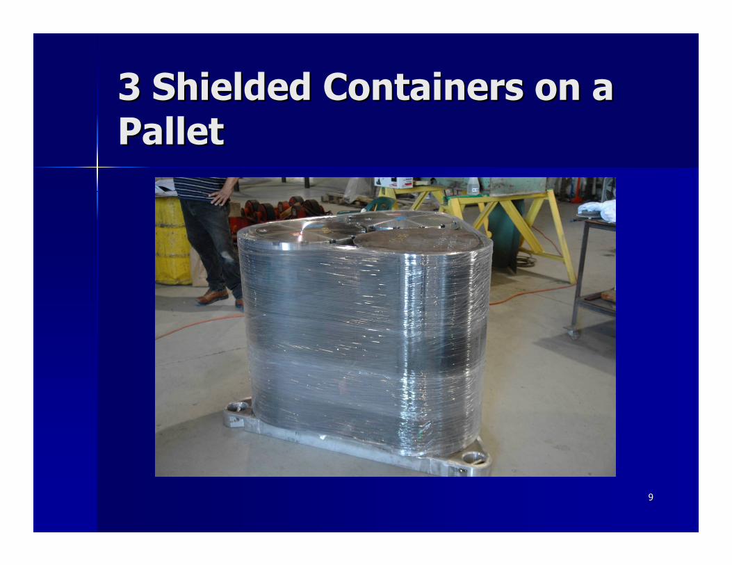
Three shielded containers are to be shipped Three shielded containers are to be shipped on a common pallet within a HalfPACTon a common pallet within a HalfPACT–– External size envelope for each container is External size envelope for each container is
approximately that of a standard 55approximately that of a standard 55--gallon drumgallon drum–– Each container contains up to a 440 lb, vented, Each container contains up to a 440 lb, vented,
3030--gallon drum of wastegallon drum of waste–– End and side shielding is maximized while End and side shielding is maximized while
staying within existing HalfPACT payload weight staying within existing HalfPACT payload weight limitslimits
–– Once assembled, the 3Once assembled, the 3--pack of shielded pack of shielded containers will remain intact all the way through containers will remain intact all the way through disposaldisposal

33
Governing Design Governing Design Requirements/Objectives Requirements/Objectives (cont.)(cont.)
Axial and radial shock absorbers are to Axial and radial shock absorbers are to surround the 3surround the 3--pack and are designed to:pack and are designed to:–– Preserve integrity of the HalfPACT containment Preserve integrity of the HalfPACT containment
boundariesboundaries–– Preserve confinement integrity of the shielded Preserve confinement integrity of the shielded
containerscontainers–– Minimize any changes in shielding characteristics Minimize any changes in shielding characteristics
during Hypothetical Accident Condition (HAC) during Hypothetical Accident Condition (HAC) eventsevents
44
Governing Design Governing Design Requirements/Objectives Requirements/Objectives (cont.)(cont.)
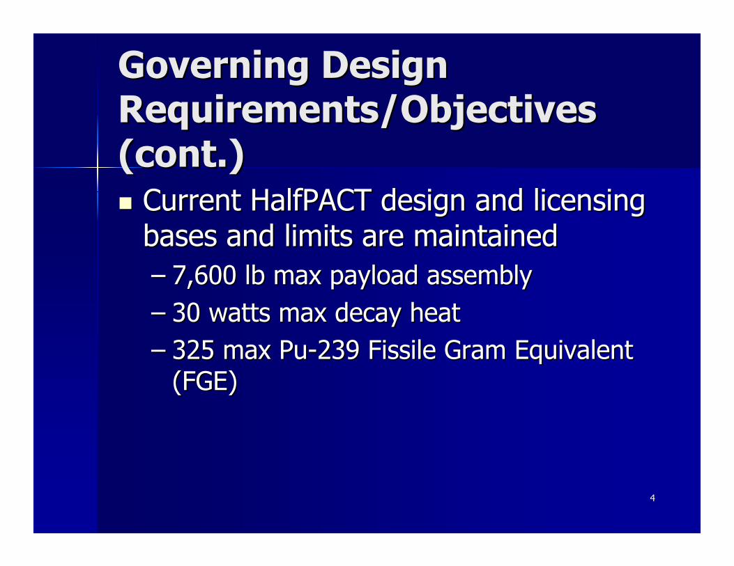
Current HalfPACT design and licensing Current HalfPACT design and licensing bases and limits are maintainedbases and limits are maintained–– 7,600 lb max payload assembly7,600 lb max payload assembly–– 30 watts max decay heat30 watts max decay heat–– 325 max Pu325 max Pu--239 Fissile Gram Equivalent 239 Fissile Gram Equivalent
(FGE)(FGE)
55
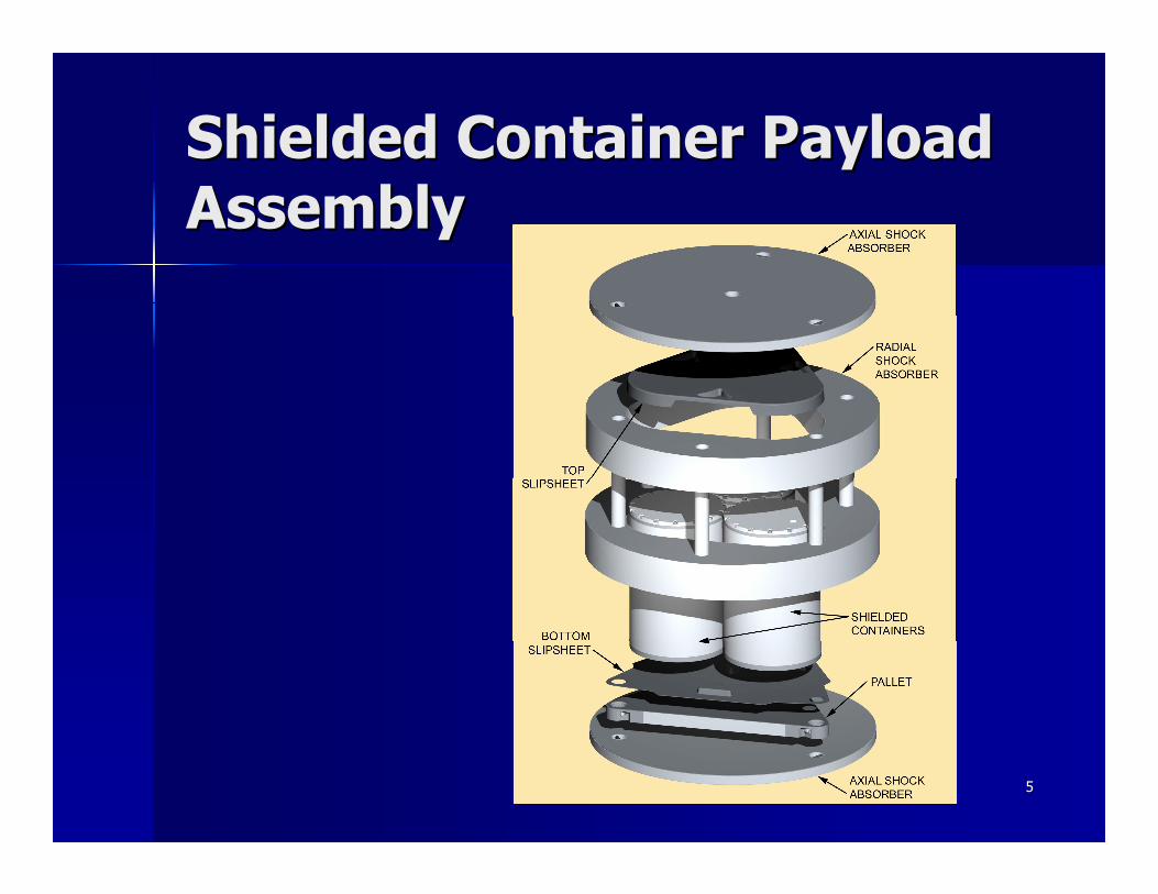
Shielded Container Payload Shielded Container Payload AssemblyAssembly
66
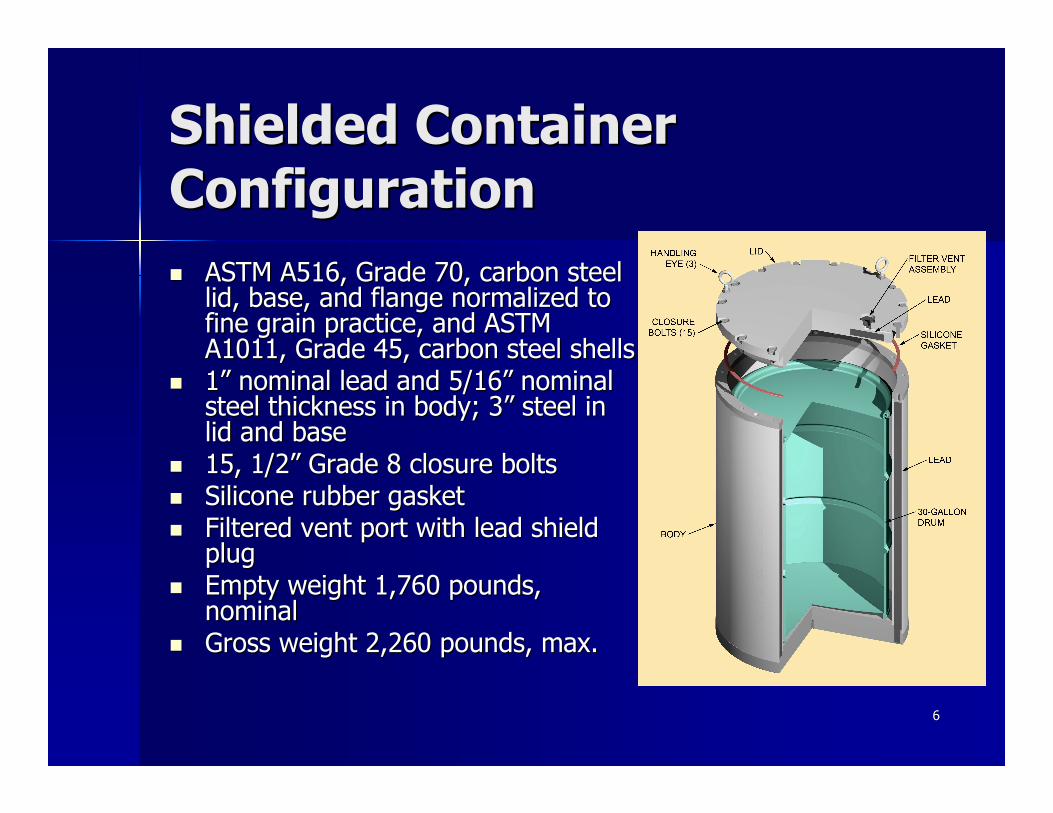
Shielded Container Shielded Container ConfigurationConfiguration
ASTM A516, Grade 70, carbon steel ASTM A516, Grade 70, carbon steel lid, base, and flange normalized to lid, base, and flange normalized to fine grain practice, and ASTM fine grain practice, and ASTM A1011, Grade 45, carbon steel shellsA1011, Grade 45, carbon steel shells1” nominal lead and 5/16” nominal 1” nominal lead and 5/16” nominal steel thickness in body; 3” steel in steel thickness in body; 3” steel in lid and baselid and base15, 1/2” Grade 8 closure bolts15, 1/2” Grade 8 closure boltsSilicone rubber gasketSilicone rubber gasketFiltered vent port with lead shield Filtered vent port with lead shield plugplugEmpty weight 1,760 pounds, Empty weight 1,760 pounds, nominalnominalGross weight 2,260 pounds, max.Gross weight 2,260 pounds, max.
77
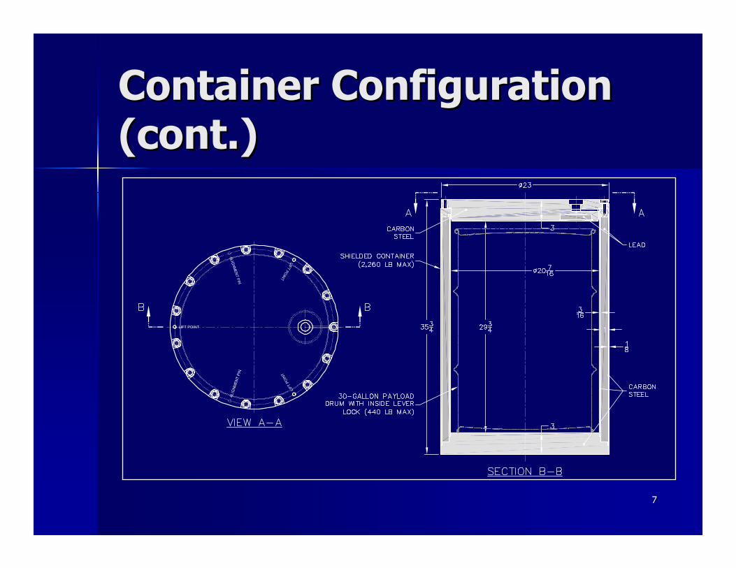
Container Configuration Container Configuration (cont.)(cont.)

88
Container Configuration Container Configuration (cont.)(cont.)
99
3 Shielded Containers on a 3 Shielded Containers on a PalletPallet

1010
Payload PalletPayload Pallet
1111
Shock Absorber Shock Absorber ConfigurationsConfigurations
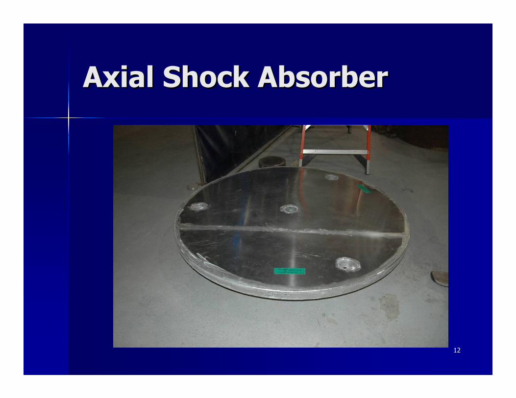
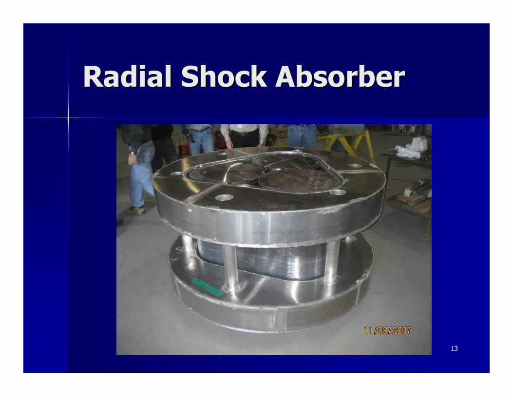
Both axial and radial shock absorbers are Both axial and radial shock absorbers are fabricated from aluminum and polyurethane fabricated from aluminum and polyurethane foam to absorb and distribute endfoam to absorb and distribute end-- and and sideside--oriented drop energyoriented drop energy–– Foam is of same type used in HalfPACT, Foam is of same type used in HalfPACT,
TRUPACTTRUPACT--II, and 72II, and 72--B PackagingsB Packagings–– Virtually all end drop energy is absorbed by axial Virtually all end drop energy is absorbed by axial
shock absorber and adjacent aluminum shock absorber and adjacent aluminum honeycomb end spacerhoneycomb end spacer
–– All side drop energy is absorbed by radial shock All side drop energy is absorbed by radial shock absorber absorber
1212
Axial Shock AbsorberAxial Shock Absorber
1313
Radial Shock AbsorberRadial Shock Absorber

1414
HAC Free Drop TestsHAC Free Drop Tests
30 foot free drops of a HalfPACT containing a 330 foot free drops of a HalfPACT containing a 3--pack of shielded containers was been performedpack of shielded containers was been performedTests conservatively ignored the presence of the Tests conservatively ignored the presence of the impact attenuating HalfPACT Outer Containment impact attenuating HalfPACT Outer Containment Assembly (OCA) and used a bare Inner Assembly (OCA) and used a bare Inner Containment Vessel (ICV)Containment Vessel (ICV)Bottom end and flat side drop test orientations are Bottom end and flat side drop test orientations are bounding bounding –– Other orientations will partially crush both axial and radial Other orientations will partially crush both axial and radial
energy absorbing components, but each to a lesser degree energy absorbing components, but each to a lesser degree than seen in the end and side drop teststhan seen in the end and side drop tests
Tests used a conservatively heavy, concreteTests used a conservatively heavy, concrete--filled, filled, 3030--gallon payload drum in each shielded container gallon payload drum in each shielded container (560 lb vs. 440 lb design basis)(560 lb vs. 440 lb design basis)
1515
HAC Free Drop Tests HAC Free Drop Tests (cont.)(cont.)
Results demonstrated:Results demonstrated:–– Overall design robustness of SCAsOverall design robustness of SCAs
Lid retained, bolt preloads unaffectedLid retained, bolt preloads unaffectedDeformations were insignificantDeformations were insignificant
–– Confinement of payloadConfinement of payloadNo release of flour/fluorescein from SCAsNo release of flour/fluorescein from SCAs
–– No significant change in shielding effectivenessNo significant change in shielding effectivenessDemonstrated by gamma scans and postDemonstrated by gamma scans and post--test test sectioning of test articlessectioning of test articles
–– No compromise to ICV containment integrity No compromise to ICV containment integrity

1616
HAC End Drop Test HAC End Drop Test DetailsDetails
End drop configuration had the ICV bottom End drop configuration had the ICV bottom stiffened to simulate the presence of the stiffened to simulate the presence of the OCAOCA–– Approach resulted in 385Approach resulted in 385gg bottombottom--end impact end impact
load measured during TRUPACTload measured during TRUPACT--II testing being II testing being significantly exceededsignificantly exceeded
One SCA inverted for bottom end drop to One SCA inverted for bottom end drop to conservatively represent top down dropconservatively represent top down drop–– Very conservative given OCA dished top head vs. Very conservative given OCA dished top head vs.
flat bottomflat bottom

1717
End Drop Test End Drop Test ConfigurationConfiguration
1818
HAC Free Drop Test VideoHAC Free Drop Test Video
1919
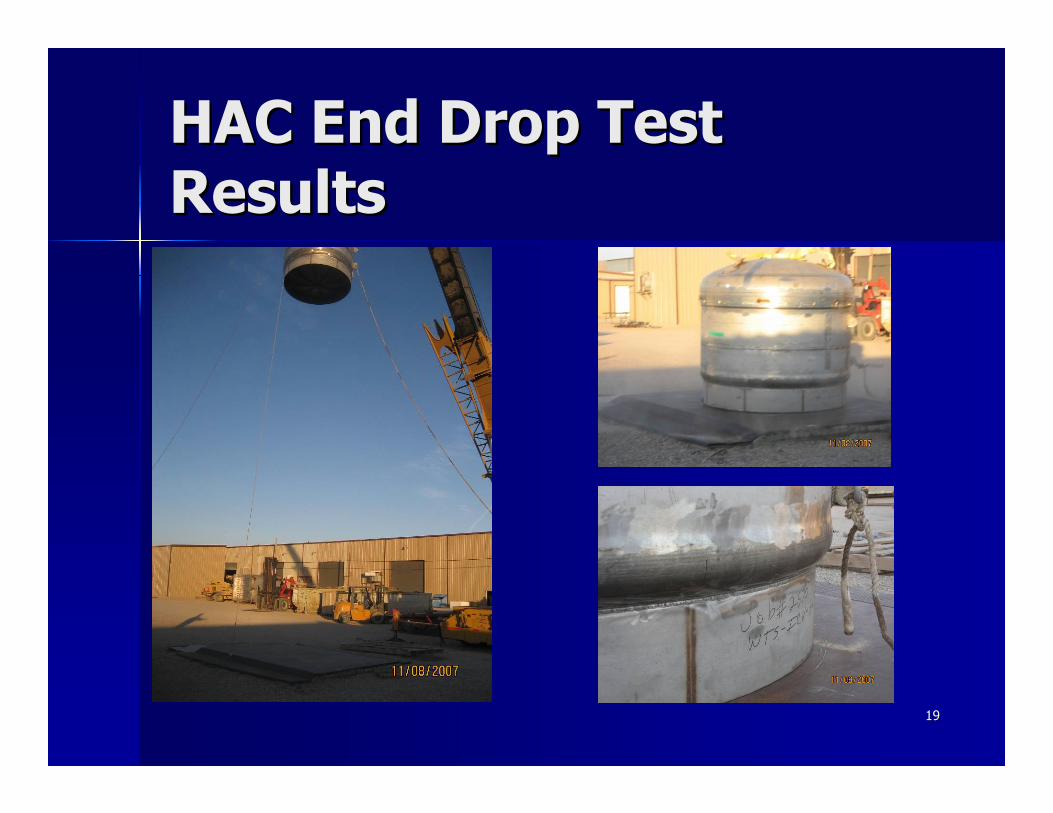
HAC End Drop Test HAC End Drop Test ResultsResults
2020
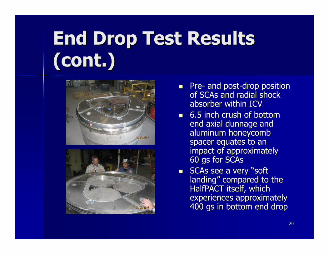
End Drop Test Results End Drop Test Results (cont.)(cont.)
PrePre-- and postand post--drop position drop position of SCAs and radial shock of SCAs and radial shock absorber within ICVabsorber within ICV6.5 inch crush of bottom 6.5 inch crush of bottom end axial dunnage and end axial dunnage and aluminum honeycomb aluminum honeycomb spacer equates to an spacer equates to an impact of approximately impact of approximately 60 gs for SCAs60 gs for SCAsSCAs see a very “soft SCAs see a very “soft landing” compared to the landing” compared to the HalfPACT itself, which HalfPACT itself, which experiences approximately experiences approximately 400 gs in bottom end drop400 gs in bottom end drop

2121
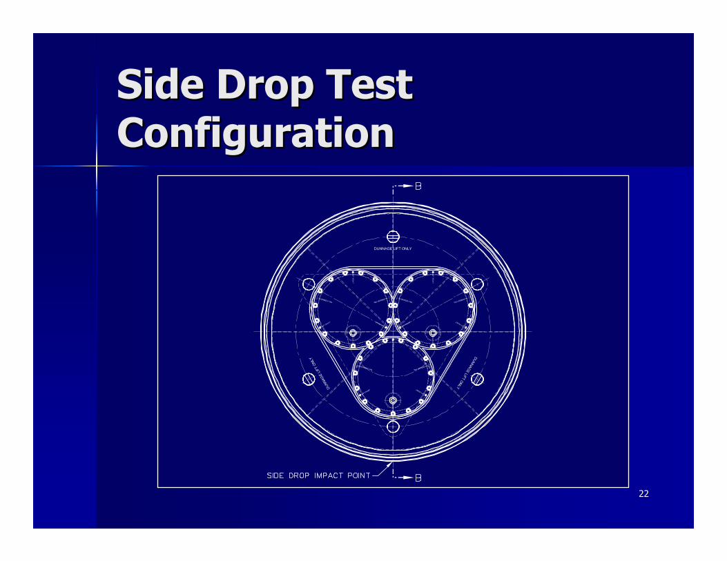
HAC Side Drop Test HAC Side Drop Test DetailsDetails
Side drop configuration aligned with Side drop configuration aligned with one shielded container vertically downone shielded container vertically down–– Maximized and concentrated load on the Maximized and concentrated load on the
bottom shielded containerbottom shielded container–– Minimized thickness of radial shock Minimized thickness of radial shock
absorber foam available to absorb impact absorber foam available to absorb impact energyenergy
9 inches at impact point9 inches at impact point
–– Maximized foam strainMaximized foam strain
2222
Side Drop Test Side Drop Test ConfigurationConfiguration

2323
HAC Side Drop Test HAC Side Drop Test ResultsResults
2424
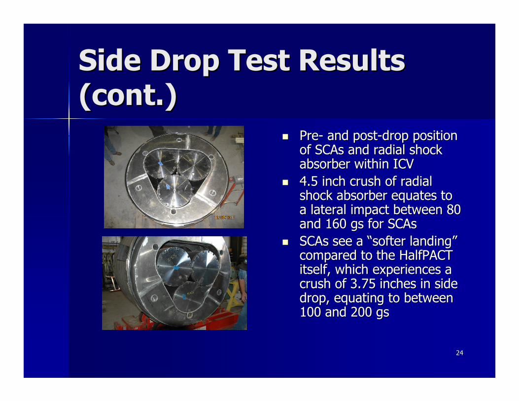
Side Drop Test Results Side Drop Test Results (cont.)(cont.)
PrePre-- and postand post--drop position drop position of SCAs and radial shock of SCAs and radial shock absorber within ICVabsorber within ICV4.5 inch crush of radial 4.5 inch crush of radial shock absorber equates to shock absorber equates to a lateral impact between 80 a lateral impact between 80 and 160 gs for SCAsand 160 gs for SCAsSCAs see a “softer landing” SCAs see a “softer landing” compared to the HalfPACT compared to the HalfPACT itself, which experiences a itself, which experiences a crush of 3.75 inches in side crush of 3.75 inches in side drop, equating to between drop, equating to between 100 and 200 100 and 200 gsgs
2525
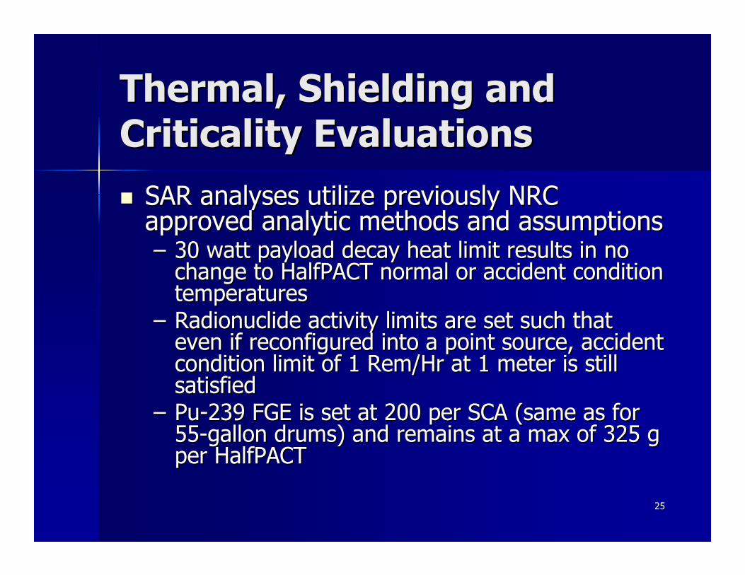
Thermal, Shielding and Thermal, Shielding and Criticality EvaluationsCriticality Evaluations
SAR analyses utilize previously NRC SAR analyses utilize previously NRC approved analytic methods and assumptionsapproved analytic methods and assumptions–– 30 watt payload decay heat limit results in no 30 watt payload decay heat limit results in no
change to HalfPACT normal or accident condition change to HalfPACT normal or accident condition temperaturestemperatures
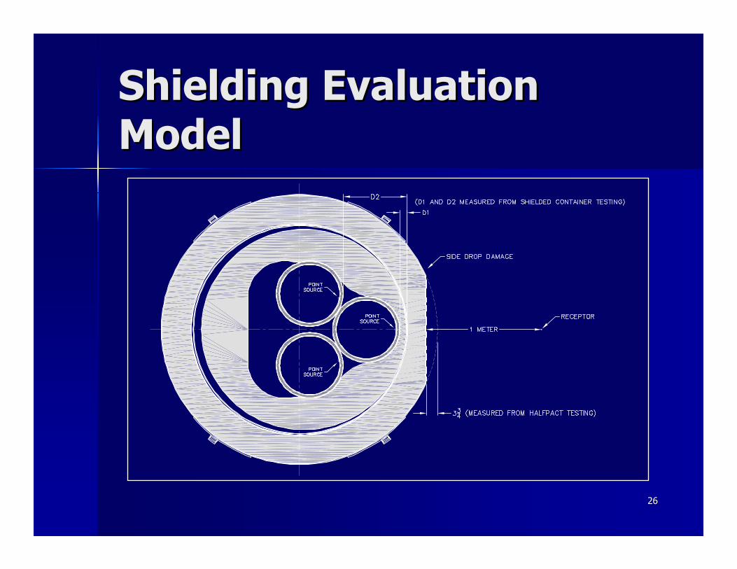
–– Radionuclide activity limits are set such that Radionuclide activity limits are set such that even if reconfigured into a point source, accident even if reconfigured into a point source, accident condition limit of 1 condition limit of 1 RemRem/Hr at 1 meter is still /Hr at 1 meter is still satisfiedsatisfied
–– PuPu--239 FGE is set at 200 per SCA (same as for 239 FGE is set at 200 per SCA (same as for 5555--gallon drums) and remains at a max of 325 g gallon drums) and remains at a max of 325 g per HalfPACTper HalfPACT
2626
Shielding Evaluation Shielding Evaluation ModelModel

2727
SummarySummary
Shielded containers are a robust, safe, and Shielded containers are a robust, safe, and more efficient alternative to shipping all RHmore efficient alternative to shipping all RH--TRU waste in the 72TRU waste in the 72--B caskB caskTesting has demonstrated that the radial Testing has demonstrated that the radial and axial shock absorbers in conjunction and axial shock absorbers in conjunction with the honeycomb end spacers protect with the honeycomb end spacers protect and preserve the shielding capabilities of and preserve the shielding capabilities of the shielded containers and protect the the shielded containers and protect the HalfPACT ICVHalfPACT ICV


![arXiv:1710.03098v2 [nucl-ex] 13 Mar 2018 · After removal from the pool, spent fuel is typically placed in long-term storage within large, heavily shielded containers called dry storage](https://img.pdfslide.net/doc/110x75/5ea6e67ccf7f1851e21bc389/arxiv171003098v2-nucl-ex-13-mar-2018-after-removal-from-the-pool-spent-fuel.jpg)