Embed Size (px)
Citation preview
Design Overview of the DM Radio Pathfinder Experiment
1Maximiliano Silva-Feaver, 1Saptarshi Chaudhuri, 3Hsaio-Mei
Cho, 2Carl Dawson, 1Peter Graham, 1,3Kent Irwin,
1Stephen Kuenstner, 3Dale Li, 1Jeremy Mardon, 5Harvey
Moseley, 2Richard Mule, 1Arran Phipps, 4Surjeet Rajendran,
2Zach Steffen, 2Betty Young
1Stanford University, Stanford, California 94305
2Santa Clara University, Santa Clara, California 95053
3SLAC National Accelerator Laboratory, Menlo Park, California 94025
4University of California Berkeley, Berkeley, California 94720
5NASA Goddard Space Flight Center, Greenbelt, Maryland 20771
Abstract
We introduce the DM Radio, a dual search for axion and hidden photon dark matter using a tun-
able superconducting lumped-element resonator. We discuss the prototype DM Radio Pathfinder
experiment, which will probe hidden photons in the 500 peV (100 kHz)-50 neV (10 MHz) mass
range. We detail the design of the various components: the LC resonant detector, the resonant fre-
quency tuning procedure, the differential SQUID readout circuit, the shielding, and the cryogenic
mounting structure. We present the current status of the pathfinder experiment and illustrate its
potential science reach in the context of the larger experimental program.
1
arX
iv:1
610.
0934
4v1
[as
tro-
ph.I
M]
28
Oct
201
6

I. INTRODUCTION
Over the past three decades, there have been numerous experimental efforts aimed at the
direct detection of dark matter, with the greatest focus on the theoretically favored Weakly
Interacting Massive Particle (WIMP). So far, all experiments have returned null results
despite having searched over a large range of mass and interaction cross-sections. Recently,
there has been increased theoretical and experimental interest in searching for ultra-light
dark matter candidates. [1]-[5] Chief among these candidates are the axion and the hidden
photon. The axion is a pseudoscalar, spin-0 particle. In addition to being a natural dark
matter candidate (owing to its theoretically predicted small couplings to baryonic matter),
it may also solve the strong CP problem, which addresses the apparent absence of CP
violation in quantum chromodynamics[6]. The hidden photon is a vector, spin-1 particle
that naturally appears in many extensions of the Standard Model. Hidden-photon dark
matter would likely be generated by cosmic inflation[4].
Both the axion and hidden photon are predicted to have a small, but nonzero, coupling
to photons. DM Radio is an experiment to search for hidden photons and axions using a
tunable superconducting lumped-element resonator. It will instrument ∼1 m3 of sample
volume at 10 mK temperature in a dilution refrigerator. The search will have sensitivity to
axions and hidden photons over a wide range of mass and coupling[7]. In this paper, we
discuss the experimental design of the initial DM Radio Pathfinder experiment.
II. METHOD OF DETECTION
While the full DM Radio experiment will probe both axions and hidden photons, the
DM Radio Pathfinder is designed to probe only hidden photon dark matter, which does not
require a large dc magnetic field for detection[8]. Hidden photons interact with photons via
a kinetic mixing interaction. The strength of this interaction is parametrized by a mixing
angle ε, which is known to be less than 10−6. We are interested in probing hidden photons of
mass below 1 meV, for which the local number density is extremely high–over 1014 particles
per cubic centimeter. Therefore, the hidden photon field may be represented as a classical
vector field–in particular, a time-varying effective current density field permeating all space.
The oscillation frequency is determined by the mass: νγ′ = mγ′c2/h, where mγ′ is the hidden
2
photon mass, c is the speed of light, and h is Planck’s constant. Because of the kinetic energy
of the hidden photon, which is set by the dark matter virial velocity 10−3c, the bandwidth
of the hidden-photon signal is 10−6νγ′ . Furthermore, the virial velocity endows the current
density field with a macroscopic coherence length 1000c/νγ′ , over which the field is spatially
uniform. For a 1 meV hidden photon, this coherence length is 1.2 meters and longer than
any detector that we discuss in this paper. As such, we can treat the hidden-photon field as
being uniform within our detector volume.
A superconducting shield encloses the detector. The cylindrical shield blocks external
electromagnetic fields, but is penetrated by the hidden photon field. The hidden photon
effective current density produces a circumferential magnetic field inside the shield. The
magnetic field generated by the hidden photon effective current is shown in Fig. 1 in the
case that the detector axis is aligned with the effective current. A toroidal sheath with a
circular slit (shown at the top in Fig. 2) couples to this field. A SQUID attached across
the slit senses the screening currents. This system is, in principle, sensitive to hidden
photons across a broad bandwidth; however, the signal to noise ratio is low. To increase the
sensitivity, a solenoidal inductor is wrapped around the sheath, and connected in series to a
parallel-plate capacitor. (Fig. 2) When the resonance frequency equals the hidden photon
frequency, the resonator rings up the screening current, increasing the signal to noise ratio.
We target a quality factor of Q ∼ 106, matching the resonator bandwidth with the dark
matter signal bandwidth. A tunable LC resonator may be realized by changing the number
of turns in the solenoid or by adjusting the position of an insertable sapphire dielectric
between the capacitor electrodes. Below, we discuss in more detail the various components
of the detector design: the resonant detector, the tuning procedure, the SQUID readout,
the shielding, and the cryogenic mounting structure. For a detailed discussion of the general
design constraints (not specific to the Pathfinder) and experiment sensitivity, see [7].
III. PROTOTYPE DESIGN
The full prototype instrument is shown in figure 3. The detection circuit, consisting of
a slitted pickup sheath and a tunable LC resonator, is located inside the superconducting
shield at the bottom of the probe.
The shield is attached to a stainless steel mounting structure which is used to secure
3

FIG. 1. The magnetic field generated in the closed toroidal sheath is shown in top view (left),
cross-sectional view (middle), and front view (right). The front view (right) also shows the super-
conducting shield that blocks external electromagnetic interference — this shield is not shown in
the left or middle view.
FIG. 2. To increase the signal-to-noise ratio of the signal, a superconducting solenoidal inductor
coil with (screened) inductance L is wrapped around the toroidal pickup sheath, and connected
in series to a superconducting tunable capacitor of value C (left). The sheath has a slit cut cir-
cumferentially at the top; screening currents are inductively coupled to a SQUID that is connected
across this slit (right). This high-Q circuit has a resonance ν0 = 12π√LC
. If a hidden-photon field
drives this circuit on resonance, the resonator rings up, increasing the amplitude of the screening
current driven through the SQUID.
the experiment in a cryoperm-lined liquid helium dewar. This mounting structure and
the shielding are described in section IIIB. The wiring and readout electronics have been
designed to minimize readout noise and pickup. The cold readout circuitry, including a
SQUID amplifier, will be housed in a separate shielded annex below the experiment (pink).
The annex, SQUID, and readout chain are discussed in section IIIC.
4
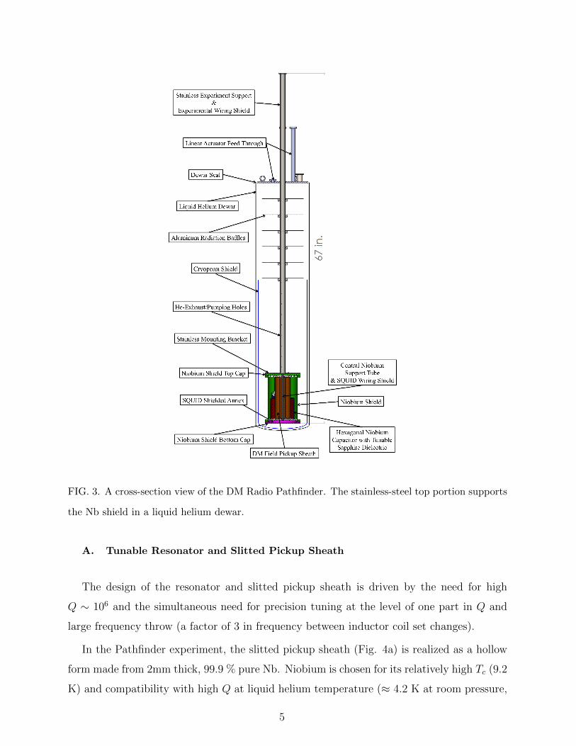
FIG. 3. A cross-section view of the DM Radio Pathfinder. The stainless-steel top portion supports
the Nb shield in a liquid helium dewar.
A. Tunable Resonator and Slitted Pickup Sheath
The design of the resonator and slitted pickup sheath is driven by the need for high
Q ∼ 106 and the simultaneous need for precision tuning at the level of one part in Q and
large frequency throw (a factor of 3 in frequency between inductor coil set changes).
In the Pathfinder experiment, the slitted pickup sheath (Fig. 4a) is realized as a hollow
form made from 2mm thick, 99.9 % pure Nb. Niobium is chosen for its relatively high Tc (9.2
K) and compatibility with high Q at liquid helium temperature (≈ 4.2 K at room pressure,
5
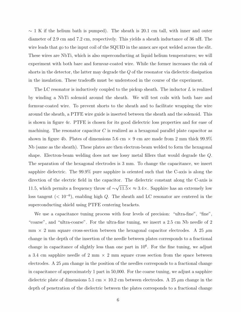
∼ 1 K if the helium bath is pumped). The sheath is 20.1 cm tall, with inner and outer
diameter of 2.9 cm and 7.2 cm, respectively. This yields a sheath inductance of 36 nH. The
wire leads that go to the input coil of the SQUID in the annex are spot welded across the slit.
These wires are NbTi, which is also superconducting at liquid helium temperatures; we will
experiment with both bare and formvar-coated wire. While the former increases the risk of
shorts in the detector, the latter may degrade the Q of the resonator via dielectric dissipation
in the insulation. These tradeoffs must be understood in the course of the experiment.
The LC resonator is inductively coupled to the pickup sheath. The inductor L is realized
by winding a NbTi solenoid around the sheath. We will test coils with both bare and
formvar-coated wire. To prevent shorts to the sheath and to facilitate wrapping the wire
around the sheath, a PTFE wire guide is inserted between the sheath and the solenoid. This
is shown in figure 4c. PTFE is chosen for its good dielectric loss properties and for ease of
machining. The resonator capacitor C is realized as a hexagonal parallel plate capacitor as
shown in figure 4b. Plates of dimensions 5.6 cm × 9 cm are made from 2 mm thick 99.9%
Nb (same as the sheath). These plates are then electron-beam welded to form the hexagonal
shape. Electron-beam welding does not use lossy metal fillers that would degrade the Q.
The separation of the hexagonal electrodes is 3 mm. To change the capacitance, we insert
sapphire dielectric. The 99.9% pure sapphire is oriented such that the C-axis is along the
direction of the electric field in the capacitor. The dielectric constant along the C-axis is
11.5, which permits a frequency throw of ∼√
11.5× ≈ 3.4×. Sapphire has an extremely low
loss tangent (< 10−6), enabling high Q. The sheath and LC resonator are centered in the
superconducting shield using PTFE centering brackets.
We use a capacitance tuning process with four levels of precision: “ultra-fine”, “fine”,
“coarse”, and “ultra-coarse”. For the ultra-fine tuning, we insert a 2.5 cm Nb needle of 2
mm × 2 mm square cross-section between the hexagonal capacitor electrodes. A 25 µm
change in the depth of the insertion of the needle between plates corresponds to a fractional
change in capacitance of slightly less than one part in 106. For the fine tuning, we adjust
a 3.4 cm sapphire needle of 2 mm × 2 mm square cross section from the space between
electrodes. A 25 µm change in the position of the needles corresponds to a fractional change
in capacitance of approximately 1 part in 50,000. For the coarse tuning, we adjust a sapphire
dielectric plate of dimensions 5.1 cm × 10.2 cm between electrodes. A 25 µm change in the
depth of penetration of the dielectric between the plates corresponds to a fractional change
6
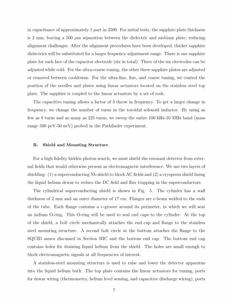
in capacitance of approximately 1 part in 2500. For initial tests, the sapphire plate thickness
is 2 mm, leaving a 500 µm separation between the dielectric and niobium plate, reducing
alignment challenges. After the alignment procedures have been developed, thicker sapphire
dielectrics will be substituted for a larger frequency adjustment range. There is one sapphire
plate for each face of the capacitor electrode (six in total). Three of the six electrodes can be
adjusted while cold. For the ultra-coarse tuning, the other three sapphire plates are adjusted
or removed between cooldowns. For the ultra-fine, fine, and coarse tuning, we control the
position of the needles and plates using linear actuators located on the stainless steel top
plate. The sapphire is coupled to the linear actuators by a set of rods.
The capacitive tuning allows a factor of 3 throw in frequency. To get a larger change in
frequency, we change the number of turns in the toroidal solenoid inductor. By using as
few as 8 turns and as many as 225 turns, we sweep the entire 100 kHz-10 MHz band (mass
range 500 peV-50 neV) probed in the Pathfinder experiment.
B. Shield and Mounting Structure
For a high fidelity hidden photon search, we must shield the resonant detector from exter-
nal fields that would otherwise present as electromagnetic interference. We use two layers of
shielding: (1) a superconducting Nb shield to block AC fields and (2) a cryoperm shield lining
the liquid helium dewar to reduce the DC field and flux trapping in the superconductors.
The cylindrical superconducting shield is shown in Fig. 5. The cylinder has a wall
thickness of 2 mm and an outer diameter of 17 cm. Flanges are e-beam welded to the ends
of the tube. Each flange contains a v-groove around its perimeter, in which we will seat
an indium O-ring. This O-ring will be used to seal end caps to the cylinder. At the top
of the shield, a bolt circle mechanically attaches the end cap and flange to the stainless
steel mounting structure. A second bolt circle at the bottom attaches the flange to the
SQUID annex discussed in Section IIIC and the bottom end cap. The bottom end cap
contains holes for draining liquid helium from the shield. The holes are small enough to
block electromagnetic signals at all frequencies of interest.
A stainless-steel mounting structure is used to raise and lower the detector apparatus
into the liquid helium bath. The top plate contains the linear actuators for tuning, ports
for dewar wiring (thermometry, helium level sensing, and capacitive discharge wiring), ports
7
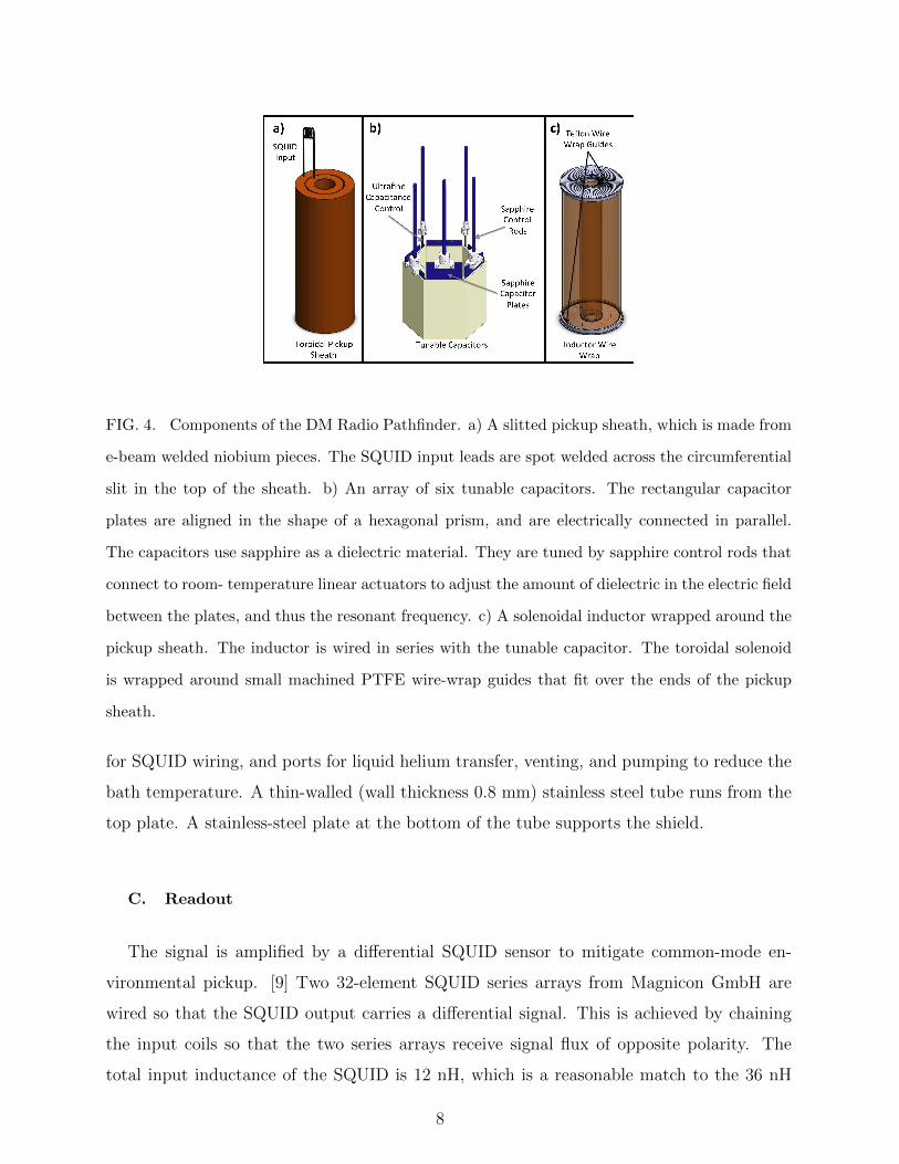
FIG. 4. Components of the DM Radio Pathfinder. a) A slitted pickup sheath, which is made from
e-beam welded niobium pieces. The SQUID input leads are spot welded across the circumferential
slit in the top of the sheath. b) An array of six tunable capacitors. The rectangular capacitor
plates are aligned in the shape of a hexagonal prism, and are electrically connected in parallel.
The capacitors use sapphire as a dielectric material. They are tuned by sapphire control rods that
connect to room- temperature linear actuators to adjust the amount of dielectric in the electric field
between the plates, and thus the resonant frequency. c) A solenoidal inductor wrapped around the
pickup sheath. The inductor is wired in series with the tunable capacitor. The toroidal solenoid
is wrapped around small machined PTFE wire-wrap guides that fit over the ends of the pickup
sheath.
for SQUID wiring, and ports for liquid helium transfer, venting, and pumping to reduce the
bath temperature. A thin-walled (wall thickness 0.8 mm) stainless steel tube runs from the
top plate. A stainless-steel plate at the bottom of the tube supports the shield.
C. Readout
The signal is amplified by a differential SQUID sensor to mitigate common-mode en-
vironmental pickup. [9] Two 32-element SQUID series arrays from Magnicon GmbH are
wired so that the SQUID output carries a differential signal. This is achieved by chaining
the input coils so that the two series arrays receive signal flux of opposite polarity. The
total input inductance of the SQUID is 12 nH, which is a reasonable match to the 36 nH
8
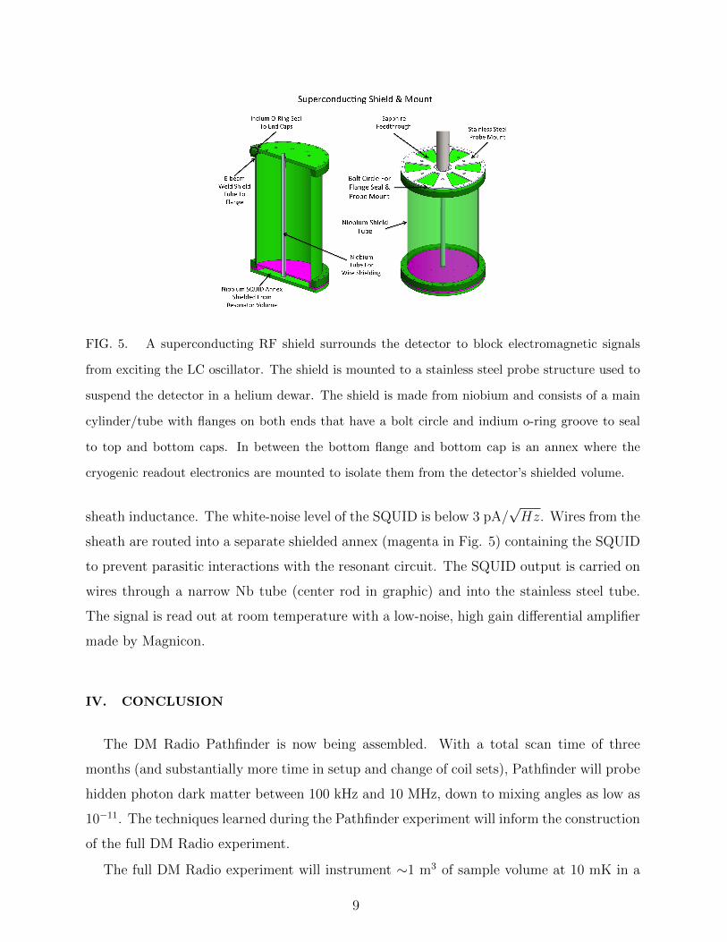
FIG. 5. A superconducting RF shield surrounds the detector to block electromagnetic signals
from exciting the LC oscillator. The shield is mounted to a stainless steel probe structure used to
suspend the detector in a helium dewar. The shield is made from niobium and consists of a main
cylinder/tube with flanges on both ends that have a bolt circle and indium o-ring groove to seal
to top and bottom caps. In between the bottom flange and bottom cap is an annex where the
cryogenic readout electronics are mounted to isolate them from the detector’s shielded volume.
sheath inductance. The white-noise level of the SQUID is below 3 pA/√Hz. Wires from the
sheath are routed into a separate shielded annex (magenta in Fig. 5) containing the SQUID
to prevent parasitic interactions with the resonant circuit. The SQUID output is carried on
wires through a narrow Nb tube (center rod in graphic) and into the stainless steel tube.
The signal is read out at room temperature with a low-noise, high gain differential amplifier
made by Magnicon.
IV. CONCLUSION
The DM Radio Pathfinder is now being assembled. With a total scan time of three
months (and substantially more time in setup and change of coil sets), Pathfinder will probe
hidden photon dark matter between 100 kHz and 10 MHz, down to mixing angles as low as
10−11. The techniques learned during the Pathfinder experiment will inform the construction
of the full DM Radio experiment.
The full DM Radio experiment will instrument ∼1 m3 of sample volume at 10 mK in a
9
dilution refrigerator. It will use dc SQUID amplifiers at the lowest frequency, dissipationless
ac SQUIDs[10] at mid-frequencies, and parametric amplifiers at higher frequencies. The full
DM Radio will incorporate a superconducting magnet, and will be sensitive to both axions
and hidden photons. In addition to being more sensitive, DM Radio will cover a larger
frequency range.
ACKNOWLEDGMENTS
We would like to thank Gary Sloan at Santa Clara University for machining the stainless
steel probe structure and the Stanford Physics Department machine shop staff for niobium
machining. The design of the DM Radio Pathfinder experiment was supported by the Kavli
Institute for Particle Astrophysics and Cosmology (KIPAC), and the construction and op-
eration of the DM-Radio Pathfinder Experiment is supported by the Department of Energy,
Laboratory Directed Research and Development funding. Arran Phipps acknowledges sup-
port from KIPAC through a Kavli fellowship.
[1] JL Rosner, et al. Planning the Future of US Particle Physics, (Snowmass 2013): Chapter 1:
Summary. arXiv:1401.6075, 2014.
[2] Ritz, S, et al. ”Building for Discovery: Strategic Plan for US Particle Physics in the Global
Context.” HEPAP Subcommittee (2014).
[3] Arias, Paola, et al. ”WISPy Cold Dark Matter.” Journal of Cosmology and Astroparticle
Physics 2012.06: 013, 2012.
[4] P.W. Graham, J. Mardon, and S. Rajendran. Vector Dark Matter From Inflationary Fluctu-
ations, Phys. Rev. D, Vol. 93, Iss. 10, May 2016.
[5] S. Thomas and B. Cabrera. ”Detecting String-Scale QCD Axion Dark Matter.” Ax-
ions 2010. Gainesville, Florida. http://www.physics.rutgers.edu/∼scthomas/talks/Axion-LC-
Florida.pdf
[6] Peccei, Roberto D. and Helen R. Quinn, ”CP Conservation in the Presence of Pseudoparticles,”
Phys. Rev. Lett, Vol. 38, Iss. 25, Sept 1977.
10
[7] S. Chaudhuri et al., A Radio for Hidden Photon Dark Matter, Phys. Rev. D, Vol. 92, Iss. 7,
Oct 2015.
[8] Asztalos, et al, ”SQUID-Based Microwave Cavity Search for Dark-Matter Axions,” Phys. Rev.
Lett, Vol. 104, 041301, Jan 2010.
[9] D. Drung et al., SQUID Current Sensor with Differential Output, IEEE Trans. Appl. Super-
cond. Vol. 23, No. 3, Jun 2013.
[10] J.A.B. Mates et al., “Demonstration of a multiplexer of dissipationless superconducting quan-
tum interference devices.” Applied Physics Letters Vol. 92, 023514, 2008.
11