Embed Size (px)
Citation preview
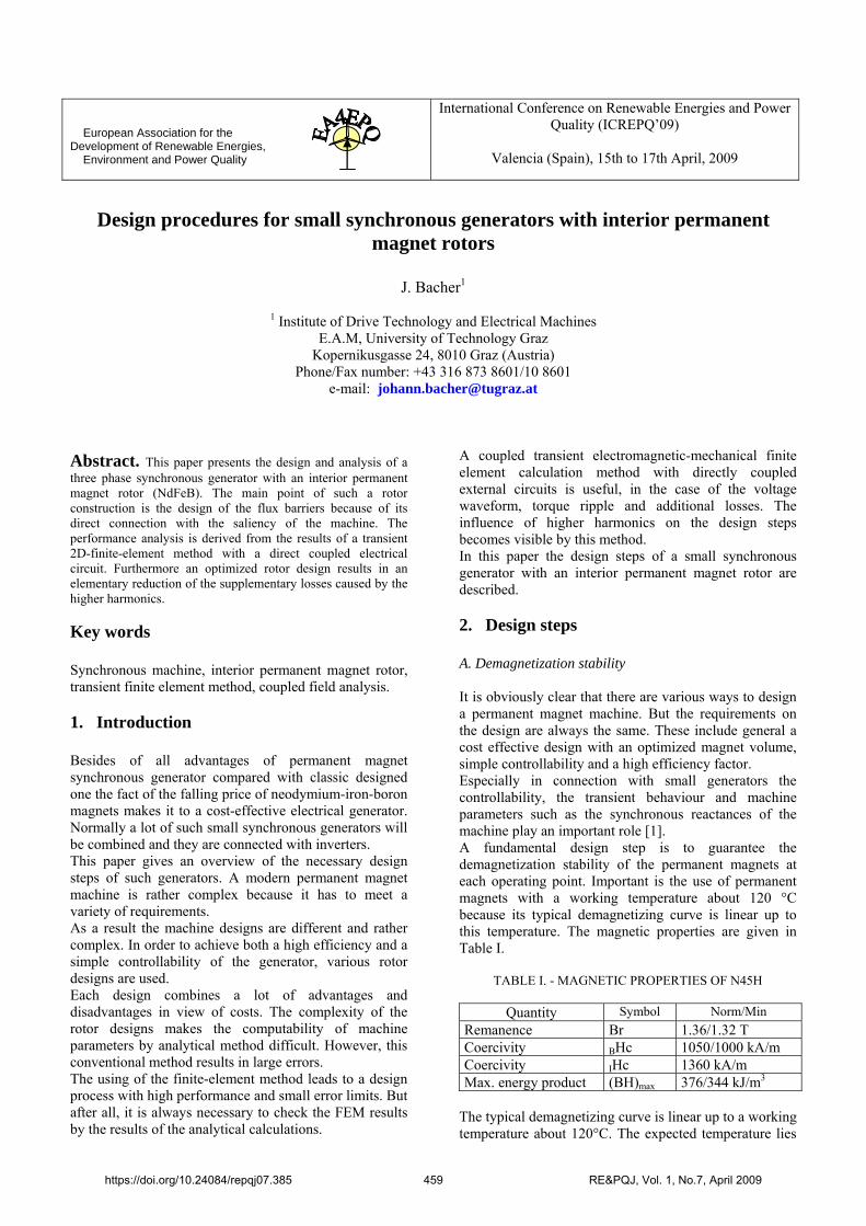
European Association for the Development of Renewable Energies, Environment and Power Quality
International Conference on Renewable Energies and Power Quality (ICREPQ’09)
Valencia (Spain), 15th to 17th April, 2009
Design procedures for small synchronous generators with interior permanent magnet rotors
J. Bacher1
1 Institute of Drive Technology and Electrical Machines E.A.M, University of Technology Graz
Kopernikusgasse 24, 8010 Graz (Austria) Phone/Fax number: +43 316 873 8601/10 8601
e-mail: [email protected]
Abstract. This paper presents the design and analysis of a three phase synchronous generator with an interior permanent magnet rotor (NdFeB). The main point of such a rotor construction is the design of the flux barriers because of its direct connection with the saliency of the machine. The performance analysis is derived from the results of a transient 2D-finite-element method with a direct coupled electrical circuit. Furthermore an optimized rotor design results in an elementary reduction of the supplementary losses caused by the higher harmonics. Key words Synchronous machine, interior permanent magnet rotor, transient finite element method, coupled field analysis. 1. Introduction Besides of all advantages of permanent magnet synchronous generator compared with classic designed one the fact of the falling price of neodymium-iron-boron magnets makes it to a cost-effective electrical generator. Normally a lot of such small synchronous generators will be combined and they are connected with inverters. This paper gives an overview of the necessary design steps of such generators. A modern permanent magnet machine is rather complex because it has to meet a variety of requirements. As a result the machine designs are different and rather complex. In order to achieve both a high efficiency and a simple controllability of the generator, various rotor designs are used. Each design combines a lot of advantages and disadvantages in view of costs. The complexity of the rotor designs makes the computability of machine parameters by analytical method difficult. However, this conventional method results in large errors. The using of the finite-element method leads to a design process with high performance and small error limits. But after all, it is always necessary to check the FEM results by the results of the analytical calculations.
A coupled transient electromagnetic-mechanical finite element calculation method with directly coupled external circuits is useful, in the case of the voltage waveform, torque ripple and additional losses. The influence of higher harmonics on the design steps becomes visible by this method. In this paper the design steps of a small synchronous generator with an interior permanent magnet rotor are described. 2. Design steps A. Demagnetization stability It is obviously clear that there are various ways to design a permanent magnet machine. But the requirements on the design are always the same. These include general a cost effective design with an optimized magnet volume, simple controllability and a high efficiency factor. Especially in connection with small generators the controllability, the transient behaviour and machine parameters such as the synchronous reactances of the machine play an important role [1]. A fundamental design step is to guarantee the demagnetization stability of the permanent magnets at each operating point. Important is the use of permanent magnets with a working temperature about 120 °C because its typical demagnetizing curve is linear up to this temperature. The magnetic properties are given in Table I.
TABLE I. - MAGNETIC PROPERTIES OF N45H
Quantity Symbol Norm/Min Remanence Br 1.36/1.32 T Coercivity BHc B 1050/1000 kA/m Coercivity IHc 1360 kA/m Max. energy product (BH)max 376/344 kJ/m3
The typical demagnetizing curve is linear up to a working temperature about 120°C. The expected temperature lies
https://doi.org/10.24084/repqj07.385 459 RE&PQJ, Vol. 1, No.7, April 2009

in the range between 70 and 80°C. The demagnetizing curve of the sintered NdFeB magnet N45H is shown in Fig. 1.
Fig. 1. The demagnetizing curve of the used magnet by
its working temperature about 120°C. The demagnetization stability of the permanent magnets must be checked for all possible electrical loads by Fig. 1. The time variation of the magnetic field strength at the nominal point presents Fig. 2. From Fig. 1 can be derived that the magnets are stable at all time.
Fig. 2. Variation of the Magnetic field strength at full load
B. Air gap flux density
Fig. 3. Computed variation of the radial air gap flux density when the motor is unloaded.
Basis of each machine design is the air gap flux density. By using of high energy permanent magnet material,
such as neodymium-iron-boron (NdFeB) the air gap flux density is around 1 Tesla. Fig. 3 shows the air gap density of the generator at no load. Fig. 4 shows the flux density plot of the 2D-FEM calculation at the working point of the machine.
Fig. 4. A 2D flux density plot of the permanent magnet
machine C. Flux barriers design Besides the stator winding layout, the air gap length and magnet material, the flux barriers design between the magnets is very important because magnetic and mechanical parameters will be influenced by it. In respect of the mechanical properties circular ends are useful. An optimum distance between the rotor surface and the hole of the magnets has to comply with the mechanical strength and the magnetic saturation. The sheet thickness of the laminated rotor is the smallest possible distance [2]. A smaller distance results in problems with the punching process of the lamina. Fig. 5 presents a principle useful rotor design.
Fig. 5. Rotor design of the test generator.
https://doi.org/10.24084/repqj07.385 460 RE&PQJ, Vol. 1, No.7, April 2009
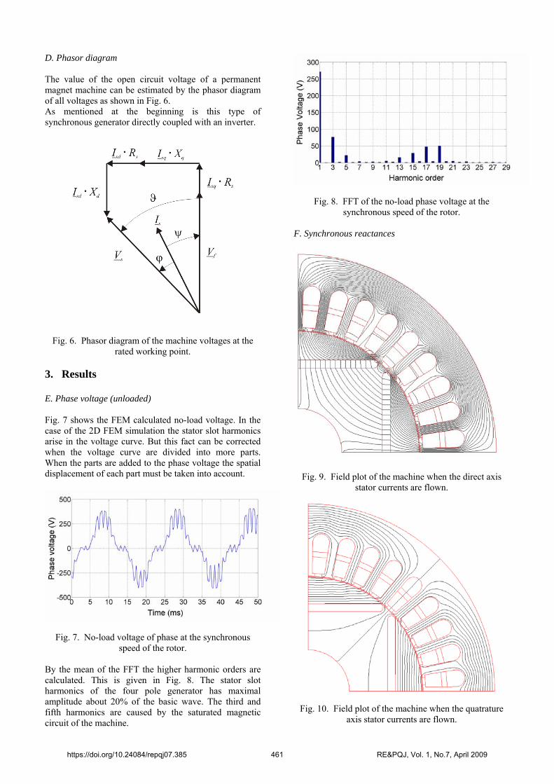
D. Phasor diagram The value of the open circuit voltage of a permanent magnet machine can be estimated by the phasor diagram of all voltages as shown in Fig. 6. As mentioned at the beginning is this type of synchronous generator directly coupled with an inverter.
Fig. 6. Phasor diagram of the machine voltages at the rated working point.
3. Results E. Phase voltage (unloaded) Fig. 7 shows the FEM calculated no-load voltage. In the case of the 2D FEM simulation the stator slot harmonics arise in the voltage curve. But this fact can be corrected when the voltage curve are divided into more parts. When the parts are added to the phase voltage the spatial displacement of each part must be taken into account.
Fig. 7. No-load voltage of phase at the synchronous speed of the rotor.
By the mean of the FFT the higher harmonic orders are calculated. This is given in Fig. 8. The stator slot harmonics of the four pole generator has maximal amplitude about 20% of the basic wave. The third and fifth harmonics are caused by the saturated magnetic circuit of the machine.
Fig. 8. FFT of the no-load phase voltage at the synchronous speed of the rotor.
F. Synchronous reactances
Fig. 9. Field plot of the machine when the direct axis stator currents are flown.
Fig. 10. Field plot of the machine when the quatrature axis stator currents are flown.
https://doi.org/10.24084/repqj07.385 461 RE&PQJ, Vol. 1, No.7, April 2009
The synchronous reactances of the internal permanent magnet motor are derived from the stored magnetic energy. For this the surface current density of the magnets are set to zero. Fig. 9 shows the field plot of the motor when the total magneto motive force (mmf), caused by the three currents of the stator winding, is aligned with the direct axis of the machine. The q-axis reaxtance can be found when the total mmf of the stator currents is aligned with the q-axis of the machine. Fig. 10 shows this field plot. The reactances can be derived by the sum of the magnetic energy. This means the magnetic energy and co-energy in the machine. The results are given in Table II.
TABLE II. - SYNCHRONOUS REACTANCES
Parameter Symbol Value d-axis reactance Xd 11.8 Ω q-axis reactance Xq 26.7 Ω
E. Losses The rotor iron losses play an important part in connection with permanent magnet motors. This is because of the higher harmonics of the magnetic field near the rotor surface. Below, the time behaviour of the magnetic flux density of the elements in the circle in Fig. 11 will be analyzed.
Fig. 11. Detail view of the rotor elements used by the FEM.
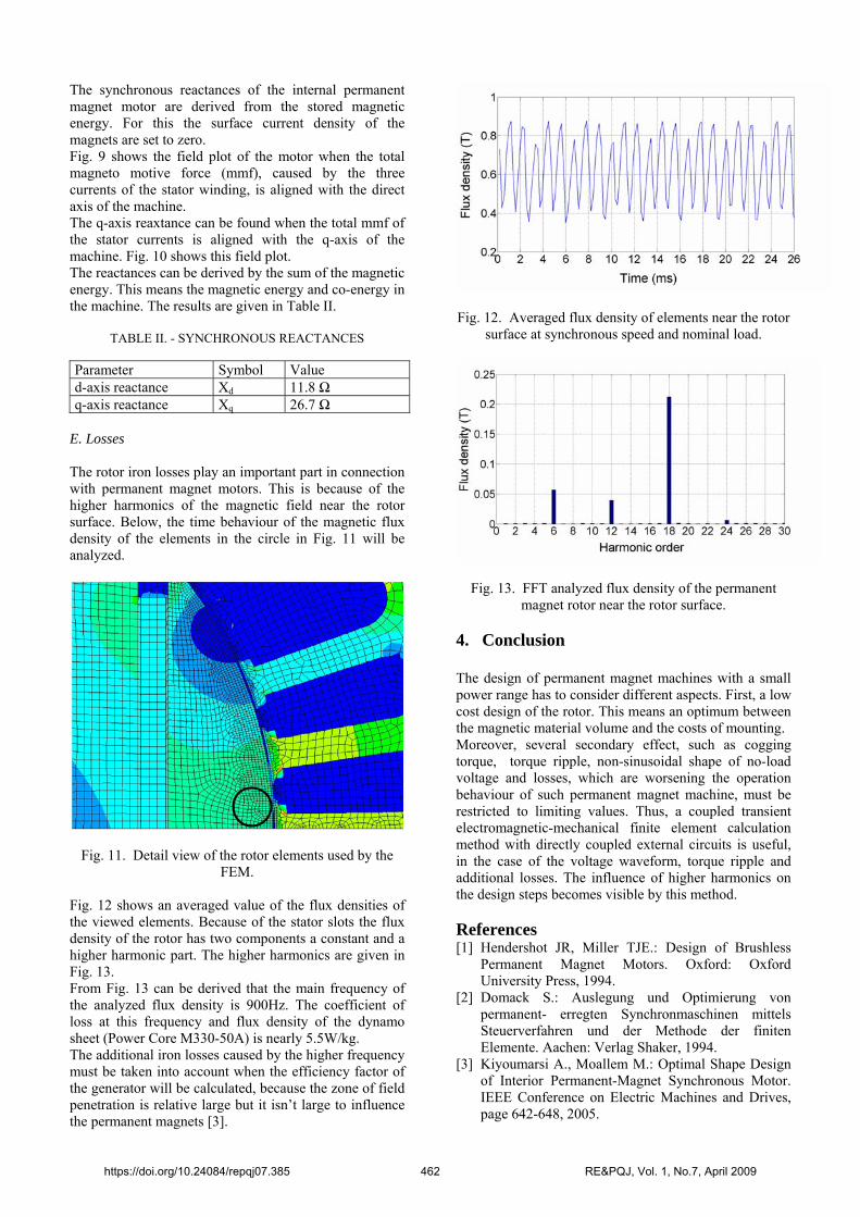
Fig. 12 shows an averaged value of the flux densities of the viewed elements. Because of the stator slots the flux density of the rotor has two components a constant and a higher harmonic part. The higher harmonics are given in Fig. 13. From Fig. 13 can be derived that the main frequency of the analyzed flux density is 900Hz. The coefficient of loss at this frequency and flux density of the dynamo sheet (Power Core M330-50A) is nearly 5.5W/kg. The additional iron losses caused by the higher frequency must be taken into account when the efficiency factor of the generator will be calculated, because the zone of field penetration is relative large but it isn’t large to influence the permanent magnets [3].
Fig. 12. Averaged flux density of elements near the rotor
surface at synchronous speed and nominal load.
Fig. 13. FFT analyzed flux density of the permanent magnet rotor near the rotor surface.
4. Conclusion The design of permanent magnet machines with a small power range has to consider different aspects. First, a low cost design of the rotor. This means an optimum between the magnetic material volume and the costs of mounting. Moreover, several secondary effect, such as cogging torque, torque ripple, non-sinusoidal shape of no-load voltage and losses, which are worsening the operation behaviour of such permanent magnet machine, must be restricted to limiting values. Thus, a coupled transient electromagnetic-mechanical finite element calculation method with directly coupled external circuits is useful, in the case of the voltage waveform, torque ripple and additional losses. The influence of higher harmonics on the design steps becomes visible by this method. References [1] Hendershot JR, Miller TJE.: Design of Brushless
Permanent Magnet Motors. Oxford: Oxford University Press, 1994.
[2] Domack S.: Auslegung und Optimierung von permanent- erregten Synchronmaschinen mittels Steuerverfahren und der Methode der finiten Elemente. Aachen: Verlag Shaker, 1994.
[3] Kiyoumarsi A., Moallem M.: Optimal Shape Design of Interior Permanent-Magnet Synchronous Motor. IEEE Conference on Electric Machines and Drives, page 642-648, 2005.
https://doi.org/10.24084/repqj07.385 462 RE&PQJ, Vol. 1, No.7, April 2009


![Book, The Electric Generators Handbook Synchronous Generators[1]](https://img.pdfslide.net/doc/110x75/552a938b55034689428b46a1/book-the-electric-generators-handbook-synchronous-generators1.jpg)