Embed Size (px)
Citation preview
5 . Design Process I
1 5.1 Introduction
~
i
This chapter presents the issues relevant to the design of flow-measuring flumes: satisfying flume design criteria, meeting the conditions of the channel in which the
Guidelines are provided for designing structures for some of the common conditions encountered, and the design process is presented and illustrated with examples.
I measuring structure is placed, and satisfying the objectives of the designer.
The methods presented in this book can be used to design a flow-measurement or flow-control structure in a channel of arbitrary shape and size, provided that an acceptable structure is feasible. The shapes of the approach and tailwater channels may be different. Most natural and artificial channels can be modeled using one of the following shapes:
Simple trapezoid, Rectangle, V-shape, Circle, U-shape, Parabola, or Complex trapezoid.
The size of the channel cross-section should be obtained from design drawings or measured in the field. Additional shapes are available for use in the flume throat to create flow contraction and provide for convenient construction. These shapes are shown in Figure 5.1.
5.2 Design Criteria
Design of long-throated flumes and broad-crested weirs should be based on the following criteria:
Critical flow should occur so that the relationship between upstream head and discharge is not influenced by the water level downstream from the structure. When this occurs, flow is considered modular (i.e., the structure is performing as a module). Obtaining critical flow conditions that can be reliably rated requires proper design of the throat section of the structure, i.e., sufficient sill height and appropriate width and length of the throat section (see Section 6.3.3). The structure should not raise the upstream water level so much that it overtops or damages the upstream channel, or interferes with operation of the channel (e.g., causes flow to be improperly divided upstream).
Chapter 5 167


5.3 Defining Existing-Channel Conditions
While we encourage flumes to be designed for new channel systems, it is recognized that most structures will be retrofitted into existing channels. The design procedures discussed below apply equally to both. However, our use of the term “existing channel” is also meant to apply to new channels that are proposed. Once the channel cross-section, elevations, location, etc. are proposed, from the standpoint of flume design, it becomes an existing channel.
5.3.1 Range of flows to be measured
As discussed in Section 2.4, one must consider the range of flows to be measured. This is the primary range over which an accurate flow measurement is required. There may be low flows that occur but are not of concern for accurate measurement, for example during the winter season when no water deliveries are being made from the channel. Some channels experience flood flows that also do not require accurate measurement, and thus do not influence the design of an accurate structure, except that one must ensure that the flume can pass these flood flows within the existing channel. Thus, a flume can be submerged by flood flows that are beyond the measurement range of interest, as long as it will pass the flow. (It is important to note that when a flume becomes submerged, the rating developed using the theory of Chapter 6 and the computer program in Chapter 8 is not accurate because critical depth does not occur. When submerged, the upstream head for a given flow rate will be greater than that predicted.) The range of flows can have a significant influence on the design of the structure, since all conditions must be satisfied over the full range of discharges-i.e., downstream submergence, accuracy, Froude number, freeboard, and flume dimensions.
5.3.2 Determining head-discharge relationship of existing channel
The water level at any particular point in a channel is influenced by the channel roughness and cross section properties, the flow rate, and backwater caused by flow obstructions downstream. In the absence of backwater (or drawdown) effects, the flow depth at a given discharge is uniform over the length of the channel. The flow depth under uniform flow is known as normal depth. Under uniform flow, the relationship between flow rate and water depth can be described by the well-known Manning equation
5.1
where C,, is a coefficient that depends upon units (1.0 for discharge in m3/s and distances in meters and 1.486 for discharge in ft3/s and distances in feet), A is the cross-sectional flow area, R is the hydraulic radius (area divided by wetted
Chapter 5 169

Table 5.1 Conservative values of Manning's roughness coefficient to estimate water levels downstream from a flume.
Float finished 0.018 0.020
Gunite 0.025 With algae growth 0.030
Float finished, with gravel on bottom
Earthen channels Straight and uniform, few weeds Winding, cobble bottom, clean sides Non-uniform, light vegetation on banks Not maintained, weeds and brush uncut
Masonry Cemented rubble Dry rubble, open joints
0.035 0.050 0.060 O. 150
0.030 0.035
perimeter), Sf is the friction slope (equal to the bottom slope under uniform flow), and n is the Manning roughness coefficient. Values of Manning's n for common channel materials are given in Table 5.1. If the depth-discharge relationship in the channel is governed by Equation 5.1, then we can use this equation to estimate conditions downstream from a proposed flume and to assist in flume design. When the Manning equation is valid, the relationship between depth and discharge is relatively well behaved and passes through zero depth and zero discharge. However, when the channel cross section is poorly defined, Equation 5.1 may be difficult to apply, and if the site is influenced by backwater, Equation 5.1 cannot be used at all because flow is no longer at normal depth. In either of these cases it may be easier to express the depth-discharge relationship empirically with a power equation such as
Q = K,Y," 5.2
where y2 is the water depth in the channel downstream from the proposed flume and K I is an empirical constant. The value of K I depends on the size of the channel, while the value of the power u depends on the shape of the channel. For wide and shallow channels under uniform flow (i.e., when Equation 5.1 applies), u is about 1.6, while for deep and narrow lined canals, u may be as high as 2.4. The values of K , and u can be determined by curve-fitting through two points of known discharge and depth. The necessary data can be obtained from field measurements or by analytical means, such as a detailed backwater analysis (for details, consult a hydraulics text or one of many available computer programs).
When the site is strongly influenced by backwater, the relationship given by Equation 5.2 is not adequate. For example, if the backwater is caused by a downstream weir, the depth-discharge relation will no longer pass through zero depth and zero discharge. In such cases, a modified form of Equation 5.2 has proven satisfactory for flume design work, namely
Q = K , ( Y ~ -4)' 5.3
170 Design Process
where K2 is an empirical constant that accounts for the fact that the depth is greater than zero at zero flow.
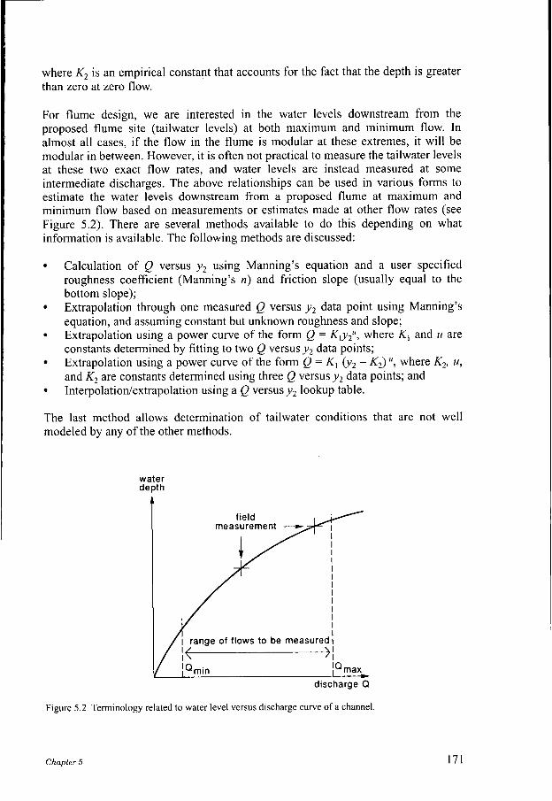
For flume design, we are interested in the water levels downstream from the proposed flume site (tailwater levels) at both maximum and minimum flow. In almost all cases, if the flow in the flume is modular at these extremes, it will be modular in between. However, it is often not practical to measure the tailwater levels at these two exact flow rates, and water levels are instead measured at some intermediate discharges. The above relationships can be used in various forms to estimate the water levels downstream from a proposed flume at maximum and minimum flow based on measurements or estimates made at other flow rates (see Figure 5.2). There are several methods available to do this depending on what information is available. The following methods are discussed:
Calculation of Q versus y2 using Manning's equation and a user specified roughness coefficient (Manning's n) and friction slope (usually equal to the bottom slope); Extrapolation through one measured Q versus y2 data point using Manning's equation, and assuming constant but unknown roughness and slope; Extrapolation using a power curve of the form Q = Kly2", where K , and u are constants determined by fitting to two Q versus y 2 data points; Extrapolation using a power curve of the form Q = KI ('y2 - K2) ", where K2, u, and K2 are constants determined using three Q versus y 2 data points; and Interpolatiodextrapolation using a Q versus y2 lookup table.
The last method allows determination of tailwater conditions that are not well modeled by any of the other methods.
water depth 4
I I I
1-1 discharge Q
Figure 5.2 Terminology related to water level versus discharge curve of a channel.
Chapter 5 171

Manning’s equation
If the flow in the downstream channel is s normal depth, tailwater depths at minimum and maximum flow can be determined using a combination of the continuity equation and Manning’s equation (5.1). When the flow in the downstream channel is at normal depth, the friction slope and bed slope of the channel are equal. For the flow in the downstream channel to be at normal depth, the downstream channel must be of uniform cross-section, slope, and roughness for a sufficient distance such that the water level at the flume site is controlled solely by the frictional resistance of the downstream channel (i.e., no backwater effects).
For a given discharge, Q, Equation 5.1 can be solved iteratively for y2 , which is embedded within the AR213 term. If a flume is to be designed in a new canal, the shape, dimensions, and bottom slope of the canal should be taken from the design drawings. However, a value of the Manning roughness coefficient should be selected that reflects the worst expected seasonal and maintenance conditions. This n-value should thus be higher than the n-value used in the canal design. The n-values given in Table 5.1 may be used for a preliminary estimate.
Manning’s equation using one Q versus y2 value
If values of the Manning roughness coefficient and bed slope are not available, a single field-measured value ofy, and the corresponding discharge can still be used to apply Manning’s equation, assuming that the slope and n-value are constant. Equation 5.1 can be rearranged to obtain
5.4
While C,,S’121n remains constant, Equation 5.4 can be applied to other discharges in the form
Q, = Q2
( A R 2 1 3 ) 2 5.5
With one depth-discharge pair known (e.g., the left side of Equation 5.5), Equation 5.5 can be solved for discharge at any other water depth. Specific values of S’and n do not need to be determined individually.
Power curve using two Q versus y 2 values
The two-point power curve method can be used regardless of whether or not the flow in the downstream channel is at normal depth. It should be noted that this method implies that at a discharge of zero, the tailwater level is also zero; The general procedure is to estimate the water depth in the channel at two discharges and then to solve Equation 5.2 based on these two data pairs. Applying Equation 5.2 to each data pair gives two equations and two unknowns, K , and u. The two data pairs can be
172 Design Process

obtained by measuring the discharge and tailwater levels at the site where the structure is to be built, by computing tailwater levels using a backwater analysis such as the standard-step or direct-step methods, or for new canals the data points may be taken from the design report. Then Equation 5.2 is used to compute water levels at Qmin and Q,u.r. To obtain the most accurate estimate of the tailwater depth at Qnlin and Q,,, the two measured data points should be as near as practical to the minimum and maximum discharges to be measured.
Power curve with offset using three Q versus y2 values
This method is similar to the two-point power curve method, except that it does not assume the tailwater level to be zero when the discharge is zero. This method might be appropriate when the downstream water level is controlled by a weir or overflow gate, so that the tailwater level is non-zero at zero discharge. Three sets of Q and y , values are required, and one of the data points must be the tailwater level at zero flow. These data are used to determine the coefficients K, , u, and K2 in Equation 5.3. Again, to obtain good estimates of the tailwater depth at Q,,, and Q,,, two of the measured data points should be as near as practical to the minimum and maximum discharges to be measured. If field data are used, the data should be obtained during the season when the downstream channel roughness is a maximum.
Q versus y, lookup table
The final method for determining tailwater levels is the use of a lookup table relating Q and y2. WinFlume can accept up to 20 pairs of Q-y2 values. Tailwater levels at discharges between the minimum and maximum flow provided in the lookup table are determined by linear interpolation; outside of the bounds of the lookup table, linear extrapolation is used. This method should only be used if none of the other methods properly describes the tailwater conditions at the site.
Example
Given:
Find:
Solution:
a canal with bottom width b = 0.30 m, side slopes of 1:1, depth d = 0.55 m, bottom slope S, = 0.00050 m/m, and a Manning roughness coefficient, n = 0.015, and a range of discharges from Qntin = 0.05 m3/s to Q,,, = O. 15 m3/s; the tailwater levels assuming water flows at normal depth (i.e., no backwater effects from downstream structures and S,= S,). Equation 5.1 can be used to determine the tailwater levels, which are y2 = 0.240 m at enli, and y , = 0.412 m at Q,u.r. Note that this requires trial and error or an iterative solution since depth is not expressed as a function of discharge. The WinFlume software described in Chapter 8 makes these calculations automatically. Solution of the Manning equation gives the following values:
Chapter 5 173
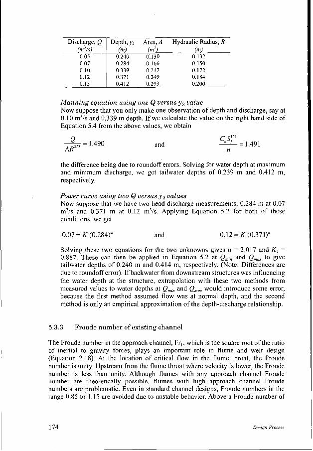
Discharge, Q I Depth, y2 Area, A Hydraulic Radius, R (m3/s) (m) (m2) (m)
0.07 0.10 0.12 0.15
e =1.490 AR^'^
0.284 0.166 0.150 0.339 0.217 O. 172 0.37 1 0.249 O. 184 0.4 12 0.293 0.200
and cusy
= 1.491 n
the difference being due to roundoff errors. Solving for water depth at maximum and minimum discharge, we get tailwater depths of 0.239 m and 0.412 m, respectively.
Power curve using two Q versus y2 values Now suppose that we have two head discharge measurements; 0.284 m at 0.07 m3/s and 0.371 m at 0.12 m3/s. Applying Equation 5.2 for both of these conditions, we get
0.07 = K, (0.284)" and 0.12 = K,(0.371)"
Solving these two equations for the two unknowns gives u = 2.017 and K, = 0.887. These can then be applied in Equation 5.2 at Qmin and Q,, to give tailwater depths of 0.240 m and 0.414 m, respectively. (Note: Differences are due to roundoff error). If backwater from downstream structures was influencing the water depth at the structure, extrapolation with these two methods from measured values to water depths at Qmin and Q,, would introduce some error, because the first method assumed flow was at normal depth, and the second method is only an empirical approximation of the depth-discharge relationship.
I 5.3.3 Froude number of existing channel
The Froude number in the approach channel, Fr,, which is the square root of the ratio of inertial to gravity forces, plays an important role in flume and weir design (Equation 2.18). At the location of critical flow in the flume throat, the Froude number is unity. Upstream from the flume throat where velocity is lower, the Froude number is less than unity. Although flumes with any approach channel Froude number are theoretically possible, flumes with high approach channel Froude numbers are problematic. Even in standard channel designs, Froude numbers in the range 0.85 to 1.15 are avoided due to unstable behavior. Above a Froude number of
174 Design Process

about 0.5, standing waves caused by channel transitions make determination of upstream water level and head subject to very large errors. To be conservative, we recommend that the Froude number in the approach channel be limited to 0.45 (although the computer design routine allows the Froude number to be as high as 0.5).
A low Froude number in the approach channel helps to reduce potential flow measurement errors in two ways. First, the measurement of upstream head is more accurate, due to the elimination of standing waves and excessive turbulence. When estimating errors in water level measurement, a Froude number of 0.2 or lower is recognized as providing a significant improvement in head-measurement un- certainty. Second, flume calibrations are less sensitive to construction anomalies at low Froude numbers. For this purpose, Froude numbers below 0.3 are preferred. However, where sedimentation is a potential problem, it may be necessary to have a large approach channel Froude number to keep sediment moving through the flume. Under these conditions, the idea is for the flume to cause a minimum reduction in approach flow velocity, regardless of the Froude number.
For a given discharge, an increase in upstream water depth will decrease the Froude number. The limit on the approach channel Froude number effectively establishes the minimum upstream water depth for that discharge, regardless of flume shape or configuration. If such a depth is feasible (i.e., does not overtop the canal) and provides adequate freeboard, then a flume can be designed that does not violate the Froude number criteria. Otherwise, a flume cannot be designed for that channel for that discharge, regardless of flume cross section or submergence considerations. The only recourse would be to enlarge the channel by increasing its width or depth.
5.3.4 Freeboard of existing channel
There is an inherent tradeoff in flume design between maximizing the amount of contraction to avoid submergence from downstream tailwater and minimizing the amount of contraction to provide adequate freeboard, to avoid overtopping the upstream channel. This is fundamental to the design process. Several methods can be used to define the required freeboard (percentage of depth, percentage of head on flume, numeric value), and even then, the designer may select a design that violates the freeboard requirements at maximum flow. In general, freeboard is provided to account for the uncertainty in the head-discharge relationship of the channel and allow for the possibility of wave action. Sources of uncertainty in the head-discharge relationship include changes in flow resistance over time, sediment deposition, or the presence of temporary obstructions. Wind and disturbances to the flow at the surface can cause waves that may overtop the canal or the lining and eventually cause damage, even though the normal water depth is within the canal prism. As discussed in Section 2.3, to estimate the risk associated with extreme events, consideration should be given to the flow rate at which the channel overtops.
The Natural Resources Conservation Service (formerly Soil Conservation Service) (SCS 1977) recommends that the freeboard be at least 20% of the maximum flow
Chapter 5 175

depth in a canal. This allows for the expected variation in normal depth in an operating canal, which can be considerable as channel roughness changes. However, when we have a flume in place, there is less uncertainty regarding the upstream depth for a given flow rate since the flume head-discharge relationship is well known. Thus for small, lined trapezoidal irrigation canals, we recommend that the canal freeboard be at least 20% of hlmUx, thus F , 2 0.2h,,,. This typically allows for an overage in discharge of about 40%, not including wave action, before the canal is overtopped. Naturally, if wave action or large operational surges are anticipated, then these must control the design freeboard. However, such conditions are not conducive to accurate flow measurement and should be avoided.
In some cases, the flume designer wants to consider a fixed freeboard depth (e.g., O. 1 m or 4 in.). This freeboard requirement does not vary as the upstream head varies with changes in the flume design. Setting a fixed freeboard allows one to set the upstream water depth for Qmux. It should be recognized that freeboard is based on the upstream water level, while the energy head of the flow may be higher. It is possible to design a flume so that it has adequate freeboard, but the energy head is actually above the top of the canal. In such cases, a disturbance to the surface of the flow could cause the canal to overtop, since the water depth, locally, can rise to the level of the energy head. Larger canals should have an engineering evaluation of the freeboard requirements, since the consequences of overtopping can be severe.
The freeboard requirement is only a concern at Q,,, while submergence of a flume is a concern at both Qmin and Q,,. Sometimes, to avoid submergence of a flume at low flows (e.g., emin), a design is required that causes violation of the freeboard requirements at Q,,. In many cases the decision must be made to provide adequate freeboard at high flows and allow the flume to become submerged at low flows. This effectively reduces the range of flows that can be measured in order to ensure the safety of the canal.
5.4 Flume Design Objectives and Issues
As discussed previously, the primary tradeoff in flume design is between enough contraction to avoid submergence, but not so much contraction that the freeboard requirement is violated. Where a canal is already flowing relatively full, it may not be possible to place a flume in the canal without overtopping at high flows or becoming submerged. In such cases, another site should be chosen for flow measurement or the canal banks must be raised. More frequently, there is a range of contraction amounts that will satisfy these two criteria. Then, within this range of contractions, other design criteria and objectives come into play.
5.4.1 Method of contraction change
One of the essential decisions in flume design is how to provide the contraction required to create critical flow within the control section. For existing lined
176 Design Process

trapezoidal irrigation canals, the most cost-effective method is to construct a broad- crested weir by placing a bottom contraction in the existing lining. However, if the properties of the resulting cross section do not satisfy one or more of the design considerations, then an alternative contraction is needed. Other options include creating a contraction from the side by bringing the sloping sidewalls in (e.g., reducing the bottom width), contracting from the side by changing the sidewalls to vertical walls (i.e., making the section rectangular), providing both a contraction from the side and bottom, or creating a complex shape that has different relative amounts of contraction over the range of discharges.
The flume design process starts with an assumed initial shape for the control section. The default is the same shape as the upstream approach channel. Then the designer must decide how the shape is to be modified to achieve the needed contraction. There are several common methods for changing the amount of contraction (Figure 5.3):
Add contraction from the bottom (raise height of sill), Raise or lower the entire section, Raise or lower the inner section (applies only to complex shapes), or Vary the amount of side contraction.
If these methods of contraction change do not provide a satisfactory design, one can combine some of the methods, for example making both a side and bottom contraction, or one can make changes to other throat cross-section dimensions, such as the side slope. The concerns here are functionality and constructability. One wants to construct the simplest, least expensive structure that will perform as needed. Thus, the general strategy is to start with the simplest shape to construct and then modify that shape if the design criteria cannot be met.
Raise or lower height of sill
With this option, the bottom of the control section is moved vertically while all the other parts remain in the same position relative to the approach channel. This, is the option to use for designing a broad-crested weir in a lined canal. In some cases, the shape actually changes with this option. For example, a sill in a U-shape could become a rectangle (bottom moved above the circular part of the U), or a trapezoid
Raise or Lower Sill Raise or Lower Entire Section
Raise or Lower Inner Section Vary Side Contraction
Figure 5.3 Methods for changing contraction amount for a flume.
Chapter 5 177

in a circle or in a parabola could become a sill in a circle or parabola, respectively. Although the newest flume design software can both raise and lower the sill, it is usually best to start with a low sill and raise it as needed.
Raise or lower entire section
With this option, the entire control section is moved up or down relative to the approach channel bottom to provide the desired amount of contraction. The shape and the dimensions of the control section do not change with this option. Hence, the amount of contraction is changed by raising or lowering the sill height, p , (p, will not be reduced below zero). This option is useful if a standard design (i.e., prefabricated) flume is to be placed in a channel. Examples include fiberglass rectangular flumes placed in an unlined channel, or a section of pipe used to make a flume throat. Such flumes are common for flow-survey work. This option could be used to test the feasibility of using standard-sized structures in an irrigation system, as opposed to designing custom structures for each site.
Raise or lower inner section
For some situations, it is necessary to construct a throat inside of an existing channel shape to provide the necessary contraction. An example would be a small trapezoid inside a pipe (i.e., Palmer-Bowlus flume). Under this contraction-change strategy, the inner trapezoid (the part that moves up and down) remains intact, with no changes in dimension values. The outer shape remains fixed, relative to the approach channel, while the inner trapezoid moves up and down. This option is useful for designing a complex flume in an existing channel, where the existing channel becomes the outer shape, or for designing a trapezoidal control within an existing channel that is circular, U-shaped, or parabolic. This option allows an efficient design without disturbing the existing channel section. (Note that the WinFlume program will not reduce the inner sill height below zero). A small trapezoid is sometimes placed within an existing trapezoidal channel to provide a wide flow measurement range, with the small trapezoid providing good measurement accuracy at low flows.
Vary side contraction
For trapezoidal flumes, as opposed to broad-crested weirs, very often the side slope angle is fixed and the design is based on changing the bottom width in the control section. Under this strategy, the vertical location of the throat does not move, and the width is adjusted to provide the needed contraction. Some shapes do not have a defined bottom width, and another appropriate dimension is changed instead to vary the width of the throat; for example, the diameter of U-shaped and circular cross sections, or the focal length of a parabola. For a trapezoid in another shape, the outer shape is assumed to match the upstream channel, so it typically is not adjustable, and the bottom width of the inner trapezoid is changed. For triangular control-section shapes, the only adjustable parameter is the side slope. For weirs with vertically movable crests as described in Section 3.5, varying the side contraction is the only design strategy that makes sense.
178 Design Process

5.4.2 Head loss design aims
For many channels, there is sufficient capacity so that at e,,, there is more available drop across the proposed flume than necessary. Under such a situation, there may be a wide range of contraction amounts (sill heights, bottom widths, etc.) that will produce an acceptable design. Assuming that other design criteria do not control the design (e.g., the Froude number limitation at maximum flow), there will be a maximum contraction amount that produces the minimum freeboard, but more head loss than needed, and there will be a minimum contraction amount that requires minimum head loss and provides more than enough freeboard (Figure 5.4). The design can be fine-tuned between these extremes by examining the tradeoffs among the various design objectives and selecting the contraction amount that provides the best overall performance.
The minimum amount of contraction often provides a good design, since under these conditions, the flume causes the least amount of change to the existing flow conditions, while still providing accurate measurement. At the same time, it provides the most safety against overtopping. If deposition of sediment being transported in the channel is a concern, this is one of the preferred options. (see Section 2.6.3 for additional options on design for sediment-laden channels). However, designing for the minimum amount of contraction also means that the design is on the verge of being submerged (unless the approach channel Froude number is controlling the design). Thus, such a design requires accurate knowledge of the tailwater conditions. Since such conditions are often not well known, such a design is a bit risky; the actual tailwater conditions may be slightly higher, causing non-modular flow and inaccurate flow measurement. Furthermore, in channels with relatively high Froude numbers, the minimum contraction amount may be limited by the approach channel Froude number requirement, so a minimum contraction design will produce a flume with a Froude number that is on the high end of the recommended range. A design with more contraction may produce a more satisfactory structure.
The maximum amount of contraction is a useful design alternative when the flow conditions in the channel are highly uncertain and the maximum flow is accurately known and controllable (as it is in many irrigation canals). Since the head-discharge relationship of the flume is accurately known, adequate freeboard can be ensured at Q,,,, and thus the design is relatively safe and requires less certain knowledge of the downstream depth-discharge relationship. For this amount of contraction, if the
I Top of canal V max v - V min
Required freeboard
--'--ff - l. 7 Tailwater
Figure 5.4 Tradeoffs in selection of contraction amount.
Chapter 5 179
Froude number is still too high, this is not a suitable site for flow measurement, unless the upstream water surface can be raised (e.g., raising the upstream sidewalls).
The usual course is to select a contraction amount that falls between these two extremes. Often the contraction amount is chosen so that the dimensions of the flume are whole numbers, if possible, or fractional numbers that do not complicate construction or imply a much higher degree of precision than needed. The exact value selected within this range depends upon the factors discussed above. However, it is usually much easier to add more contraction later than to take contraction away, especially when the contraction is made of concrete.
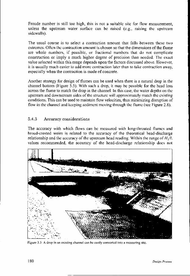
Another strategy for design of flumes can be used when there is a natural drop in the channel bottom (Figure 5.5). With such a drop, it may be possible for the head loss across the flume to match the drop in the channel. In this case, the water depths on the upstream and downstream sides of the structure will approximately match the existing conditions. This can be used to maintain flow velocities, thus minimizing disruption of flow in the channel and keeping sediment moving through the flume (see Figure 2.8).
5.4.3 Accuracy considerations
The accuracy with which flows can be measured with long-throated flumes and broad-crested weirs is related to the accuracy of the theoretical head-discharge relationship and the accuracy of the upstream head reading. Within the range of H,/L values recommended, the accuracy of the head-discharge relationship does not
Figure 5.5 A drop in an existing channel can be easily converted into a measuring site.
180 Design Process