Embed Size (px)
Citation preview
National Park Service
Repair and Upgrade Washington Monument Elevator –
Washington, DC NAMA-224923
Pre-Design Report Final Submission
September 2016
Prepared by: CH2M HILL, Inc.
Herndon, VA
Contract No. P15PC00018 Task Order No. P16PD01166
APPROVED FOR PUBLIC RELEASE

National Park Service U.S. Department of the Interior Repair and Upgrade Washington Monument Elevator National Mall and Memorial Parks, Washington, D.C.
Repair and Upgrade Washington Monument Elevator – Final September 2016 Table of Contents Page i
Table of Contents
Acronyms and Abbreviations ........................................................................................... iii
Executive Summary .................................................................................................. ES-1
Chapter 1 – Introduction .............................................................................................. 1-1
1.01 Project Description and History .................................................................... 1-1
1.02 Project Kickoff and Site Visit ........................................................................ 1-1
1.03 Deliverables ................................................................................................. 1-2
Chapter 2 – Existing Conditions .................................................................................. 2-1
2.01 Elevator ........................................................................................................ 2-1
2.02 Code Compliance ........................................................................................ 2-2
2.03 Structural ..................................................................................................... 2-3
2.04 Mechanical ................................................................................................... 2-4
2.05 Electrical ...................................................................................................... 2-5
Chapter 3 – Recommendations ................................................................................... 3-1
3.01 Elevator ........................................................................................................ 3-1
3.01.1 Maintenance and Reliability Items .......................................................... 3-1
3.02 Elevator Modernization ................................................................................ 3-1
3.03 Structural ..................................................................................................... 3-2
3.03.1 Maintenance Repairs .............................................................................. 3-2
3.03.2 Modernization Items................................................................................ 3-2
3.04 Mechanical ................................................................................................... 3-5
3.04.1 Maintenance Repairs .............................................................................. 3-5
3.04.2 Modernization ........................................................................................ 3-5
3.05 Electrical ...................................................................................................... 3-5
3.05.1 Maintenance Repairs .............................................................................. 3-5
3.05.2 Modernization ......................................................................................... 3-6
Chapter 4 – NPS Project Sustainability Checklist Summary ....................................... 4-1

National Park Service U.S. Department of the Interior Repair and Upgrade Washington Monument Elevator National Mall and Memorial Parks, Washington, D.C.
Repair and Upgrade Washington Monument Elevator – Final September 2016 Table of Contents Page ii
List of Figures Figure 1: Existing Equipment Maintenance Ratings ..................................................... 2-1
Figure 2: Elevator Access Platform at an Intermediate Level ....................................... 2-4
Figure 3: Observation Level Access to Machine Room Via Portable and Fixed Ladder ..................................................................................................................... 2-4
Figure 4: Draft Section of Proposed Ladder Access .................................................... 3-2
Figure 5: Draft Partial Plan of Proposed Platform for Access to the Elevator Machine Room ............................................................................... 3-3
Figure 6: Interior Trane PTAC Unit (AC-2) in Poor to Fair Condition ............................ 3-5
Figure 7: Peeling Skin on Cable (Left Conductor) in Siemens Circuit Breaker Panel ... 3-5
Figure 8: Mismatched Conductor Sizes (250 MCM vs 2/O) in Siemens Circuit Breaker Panel ............................................................................................................ 3-6
List of Appendices Appendix A – Operational Integrity Report Appendix B – Project Upgrade Repair Program Appendix C – Elevator Machine Test Report Appendix D – Elevator Modernization Study Appendix E – NPS Sustainability Checklist

National Park Service U.S. Department of the Interior Repair and Upgrade Washington Monument Elevator National Mall and Memorial Parks, Washington, D.C.
Repair and Upgrade Washington Monument Elevator – Final September 2016 Acronyms and Abbreviations Page iii
Acronyms and Abbreviations
AHU air-handling unit ASCE American Society of Civil Engineers ASME American Society of Mechanical Engineers ECP elevator control panel HHW heating hot water kVA kilovolt-amp(s) LED light-emitting diode LEED Leadership in Energy and Environmental Design MCM thousands of circular mils MI mineral insulated NPS National Park Service O&M operation and maintenance OSHA Occupational Safety and Health Administration PTAC packaged terminal air conditioner V Volt

National Park Service U.S. Department of the Interior Repair and Upgrade Washington Monument Elevator National Mall and Memorial Parks, Washington, D.C.
Repair and Upgrade Washington Monument Elevator – Final September 2016 Executive Summary Page ES-1
Executive Summary
In May 2016, the National Park Service (NPS) Denver Service Center contracted with CH2M for the repair and upgrade of the elevator in the Washington Monument at the National Mall and Memorial Parks in Washington, DC (Contract Number P15PC00018, Task Order P16PD01166). The scope of services consists of preparing a predesign report that focuses on the elevator repair and upgrade. Over the last several months, there have been a number of stoppages that have resulted in visitors being trapped inside the elevator cab for up to an hour. Each instance has resulted in media attention and increased scrutiny on the elevator. As a result, NPS has contracted with Quality Elevator Company, Inc. to employ a full-time onsite elevator technician to increase the repair response time when the elevator fails. CH2M and its elevator consultant Lerch Bates completed an elevator condition assessment and performed a test on the elevator motor to determine the elevator’s safety and reliability. The conclusion is that the Washington Monument elevator is safe from an operational perspective and does not require a full-time technician from Quality Elevator Company, Inc. to be onsite. However, several components of the Washington Monument, such as the portions of the elevator, controls, electrical supply, structure fire ratings, and life safety components are not up-to-date with the current code-compliant requirements. This report summarizes the existing conditions of the elevator and provides specific maintenance, reliability, and modernization recommendations and associated costs to provide a safer environment for visitors, staff, and contractors. Overall, the elevator is in good condition and the current level of maintenance is average. The assessment found the elevator system’s design and technology are outdated and cannot reliably keep up with daily demand. The elevator motor itself is in very good condition for its age (over 50 years old) and additional maintenance can prolong its life. The control system is outdated and should be upgraded as part of a modernization program. Although the majority of the elevator performance issues can be attributed to the maintenance concerns, both the maintenance and reliability recommendations should be implemented to improve the elevator’s dependability and longevity. In particular, the hoistway should be cleaned, the car sills restored, the gap on the car doors adjusted, and spare circuit board controllers kept on hand. This report also identifies modernization recommendations that should be included in an elevator modernization project, the goals of which would be to improve reliability, comply with current codes to the maximum extent feasible, and improve machine room access. At a minimum, a modernization project should include replacing the control system with microprocessor-based controls; installing new silicon controlled rectifier drive units, new closed-loop door operators, and new light-emitting diode car and hall lighting fixtures; and providing permanent ladder access to the machine room. Implementing the modernization project is anticipated to take 11 months to construct,

National Park Service U.S. Department of the Interior Repair and Upgrade Washington Monument Elevator National Mall and Memorial Parks, Washington, D.C.
Repair and Upgrade Washington Monument Elevator – Final September 2016 Executive Summary Page ES-2
and it is recommended the modernization project contract include 5 years of operation and maintenance (O&M) service.

National Park Service U.S. Department of the Interior Repair and Upgrade Washington Monument Elevator National Mall and Memorial Parks, Washington, D.C.
Repair and Upgrade Washington Monument Elevator – Final September 2016 Chapter 1 – Introduction Page 1-1
Chapter 1 – Introduction
1.01 Project Description and History Construction of the Washington Monument was completed in 1884. The obelisk structure has a bluestone gneiss foundation and walls of granite faced with marble. Throughout the years, the 125-year-old monument has been repaired and restored, with the most recent repairs occurring after the 2011 Virginia earthquake, which caused extensive damage. As the world’s tallest stone structure, an elevator is used by the public to access the 500-foot observation level. The monument has an estimated 550,000 visitors annually and the elevator is used up to 250 times per day to shuttle visitors to and from the observation deck at the top of the monument. The elevator has recurring problems, including shutdowns and stoppages that trap passengers or require visitors to walk down 896 steps to exit the monument. As a result, an elevator technician has been hired as a full-time employee and is on standby to increase the repair response time when the elevator fails. These circumstances are a financial burden to the National Park Service (NPS). In addition, accessing the elevator machine room located at the top of the monument for repairs is difficult, and remote monitoring is not available at the ground level. The elevator technician must climb 50 flights of stairs to the 500-foot level and then use two aluminum ladders to gain access to the only entry point to the elevator machine room, 19 feet above the current 500-foot level observation level.
1.02 Project Kickoff and Site Visit A kickoff meeting was held with NPS on May 25, 2016, at the National Mall and Memorial Parks Headquarters in Washington, DC. The team reviewed the project scope of services and addressed any issues or concerns. An orientation meeting was also conducted and included a tour of the Washington Monument elevator and work areas. The team also visited Bunker 1, which contains the electrical and heating, ventilation, and air conditioning equipment serving the monument. On June 8, 2016, Lerch Bates conducted a site visit and completed an audit of the elevator cab, hoistway, and elevator machine room. A representative from Quality Elevator Company, Inc., which has been contracted to be onsite for maintenance and repairs, was present to assist as necessary. This site visit was used to determine the condition of the system, the effectiveness of the maintenance activities, and code compliance. In addition to the visual review, performance measurements were taken and ride quality was evaluated with regard to operation and compared to established industry standards. The team that performed the assessments to repair and upgrade the Washington Monument elevator included the personnel listed below.

National Park Service U.S. Department of the Interior Repair and Upgrade Washington Monument Elevator National Mall and Memorial Parks, Washington, D.C.
Repair and Upgrade Washington Monument Elevator – Final September 2016 Chapter 1 – Introduction Page 1-2
Organization Team Member Role
CH2M
Mark Pratt Project Manager
Fawn Stinchcomb Assistant Project Manager
Greg Wilfley Cost Estimator
Matt Ludwig Mechanical Engineer
Roger Harte Electrical Engineer
Arnol Gillum Structural Engineer
Lerch Bates
John McGirt Regional Project Manager
Jim Turner Senior Consultant
David Curtis Field Technician
1.03 Deliverables An Operational Integrity Report was prepared and submitted to NPS to present the results of the visual observations and provide maintenance and reliability recommendations. The major concerns addressed by the maintenance recommendations are the quality of housekeeping and the lack of regular, low-cost repairs to the elevator and equipment. Routine maintenance of components can significantly reduce breakdowns, detect potential trouble spots, and fix worn components before malfunctions occur. The elevator performance evaluation and deficiency report is provided in Appendix A, Operational Integrity Report. An Upgrade Repair Program was developed to identify which elevator components should be upgraded and which should be repaired to enhance elevator safety and reliability. These recommendations are discussed in Appendix B, Project Upgrade Repair Program. On June 16, 2016, Lerch Bates performed an elevator machine test to evaluate the elevator motor. The test included an electrical signature analysis, magnetic properties test, and time-to-failure estimation. Overall, despite the age of the motor (over 50 years old), there appear to be no mechanical issues that would result in elevator malfunctions. The elevator machine test results are provided in Appendix C, Elevator Machine Test Report. A preliminary modernization plan was developed to assist NPS in providing superior reliability of the Washington Monument elevator. The condition of the existing equipment was evaluated and the components were assessed for their code compliance and whether they should be replaced or reused. It is recommended that the existing control system be replaced and new closed-loop operators and light-emitting diode (LED) fixtures be installed. Appendix D, Elevator Modernization Survey provides detailed recommendations of the preliminary modernization project.

National Park Service U.S. Department of the Interior
Repair and Upgrade Washington Monument Elevator National Mall and Memorial Parks, Washington, D.C.
Repair and Upgrade Washington Monument Elevator – Final Chapter 1 – Introduction
September 2016 Page 1-3
Appendix E contains the Project Sustainability Checklist.

National Park Service U.S. Department of the Interior Repair and Upgrade Washington Monument Elevator National Mall and Memorial Parks, Washington, D.C.
Repair and Upgrade Washington Monument Elevator – Final September 2016 Chapter 2 – Existing Conditions Page 2-1
Chapter 2 – Existing Conditions
2.01 Elevator The basic existing elevator equipment was installed in the late 1950s by Otis Elevator Company. A modernization upgrade was completed in 1997. Overall, the elevator system is in good condition for equipment from the 1950s era. However, changes in equipment design and technology have made the existing dispatching system and motor control obsolete. In addition, maintenance discrepancies observed for the elevator equipment and components can cause issues to occur more frequently than if the equipment and components were maintained on a regular schedule. Routine maintenance measures can significantly reduce breakdowns, detect potential trouble, and identify worn components before malfunction occurs. It was observed that 35% of the equipment is rated below average or unsatisfactory with regard to current operational maintenance quality.
Figure 1: Existing Equipment Maintenance Ratings
In summary, the elevator’s existing condition appears to be good, but it is likely the elevator’s performance issues are partially related to inadequate maintenance. However, despite the good condition of the existing equipment, it is likely that the design and existing technologies are outdated and cannot keep up with the high demand. Refer to Appendix A, Operational Integrity Report for more details.
Unacceptable (Rating of 1)10%
Below Average (Rating of 2)25%
Acceptable (Rating of 3)50%
Above Average (Rating of 4)10%

National Park Service U.S. Department of the Interior Repair and Upgrade Washington Monument Elevator National Mall and Memorial Parks, Washington, D.C.
Repair and Upgrade Washington Monument Elevator – Final September 2016 Chapter 2 – Existing Conditions Page 2-2
2.02 Code Compliance Significant improvements the design of the elevator components have made the elevator substantially more safe for the public and employees, as well as for first responders. However, there are many components that do meet current code requirements, such as the electrical supply, the structure’s fire ratings, and life safety elements. The list below indicates discrepancies in code compliance; additional details can be found in Section 3 of Appendix D, Elevator Modernization Survey.
Code Reference Code Compliant Discrepancies
American Society of Mechanical Engineers (ASME) A17.1 2.1.1 Partitions between hoistway and machine rooms are not fire rated.
2.1.5 No windows in the hoistway (or protected on outside).
2.1.6 Landing sills, hoistway doors, and door tracks project inside the hoistway enclosure. (See 2.11.10.1 for additional code compliance)
2.2.2.4 Drains in the pit area do not comply with code requirements and do not prevent gas and odors from entering the hoistway.
2.2.5 The lighting does not provide an illumination of not less than 100 lx (10 foot-candles) at the pit floor. The light bulbs in the elevator pit are not externally guarded to prevent contact or accidental breakage.
2.7.1.1 Machine room requires patching to be fire rated.
2.7.3.1.1 A permanent and unobstructed means of access must be provided to the machine room.
2.7.9.1.1 Light bulbs in the machine room are not externally guarded to prevent contact or accidental breakage.
2.8.3.4 Pipes must be covered to prevent leakage or condensate from entering the machinery space, machine room, control spaces, control room, or hoistway.
2.11.10.1
Landing sills are not guarded. The guard must have a straight vertical face extending below the sill not less than the depth of the leveling zone plus 3 inches. If required, the bottom of the guard must also be beveled at an angle of not less than 60 degrees and not more than 75 degrees.
2.26.10
The existing power source is incapable of absorbing the energy generated by an overhauling load. Additional means for absorbing sufficient energy to prevent elevator from attaining governor tripping speed, or a speed in excess of 125% of the rated speed, should be provided on the load side of each elevator power supply line disconnecting means.

National Park Service U.S. Department of the Interior Repair and Upgrade Washington Monument Elevator National Mall and Memorial Parks, Washington, D.C.
Repair and Upgrade Washington Monument Elevator – Final September 2016 Chapter 2 – Existing Conditions Page 2-3
Code Reference Code Compliant Discrepancies
National Electrical Code (NEC)
620-51
The 110-Volt (V) disconnect must be supplied in all elevator machine rooms such that it is in sight of elevator motor and controller and adjacent to the machine room entry door. A label on the disconnect is required that specifies the location of the overcurrent protection device.
620-85
Each 125V, single-phase, 15- and 20-ampere receptacle installed in the pits must be a ground-fault circuit-interrupter type. All 125V, single-phase, 15- and 20-ampere receptacles installed in the machine rooms and machinery spaces must have ground-fault circuit-interrupter protection for personnel.
International Building Code (IBC) 2015
1015.3
Required guards must not be less than 42 inches high measured vertically as follows: from the adjacent walking surfaces, or, on stairways and stepped aisles, from the line connecting the leading edges of the tread nosings.
1015.4 Required guards must not have openings that allow passage of a sphere 4 inches in diameter from the walking surface to the required guard height.
1607.2 and 1607.3
The Uniform Live Load must be 100 pounds per square foot. The Concentrated Live Load must be 300 pounds
2.03 Structural The Washington Monument is a freestanding stone structure with an interior steel-framed elevator core. In addition, a steel-framed stair provides access from the ground level to the 500-foot level where the observation desk is located. The stair has concrete landings every 10 feet, with concrete intermediate landings in-between each level. From a review of documents and information available at the time of this report, the elevator’s core steel framing remains from the original construction completed in 1885. It is suspected that alterations to the steel framing were made during elevator cab modifications performed since the installation of the passenger elevator in the 1950s. The elevator shaft is open between the 10-foot and 490-foot levels and is protected by wire mesh and two horizontal rails, that span between the steel elevator shaft supports; openings in the wire mesh are provided to access to the elevator shaft from the concrete stair landings on main and intermediate levels. The horizontal railing provided is approximately 36 inches high and does not meet the current building code minimum height (a minimum of 42 inches) required for a guard around an opening.

National Park Service U.S. Department of the Interior Repair and Upgrade Washington Monument Elevator National Mall and Memorial Parks, Washington, D.C.
Repair and Upgrade Washington Monument Elevator – Final September 2016 Chapter 2 – Existing Conditions Page 2-4
At 35 locations throughout the elevator’s length of travel (17 locations on the west stair landings, 18 locations on the east stair landings), a landing extending into the elevator shaft is provided for access/ emergency egress from the elevator cab (Figure 2). The platform and railing provided at these locations do not meet current building code requirements for live load (100 pounds per square foot) or the requirements for a guard system along an opening (a minimum height of 42 inches and no openings that can pass a sphere greater than 4 inches in diameter). The elevator machine room is approximately 8 feet 10 inches by 8 feet 10 inches in size and is supported by steel framing with an aluminum diamond plate flooring surface. No permanent access to the elevator machine room is provided from the observation level; access is gained using a modified aluminum ladder extension permanently attached to the elevator machine room support framing and a second portable extension ladder (Figure 3). The limited access is a concern for NPS staff and the elevator maintenance contractor. In summary, the elevator structure appears to be in good condition and it is unlikely that the structure is causing performance issues. It is likely the elevator’s performance issues are partially related to the difficulty in accessing the elevator machine room and the safety issues associated with accessibility. Further review of elevator structural framing and bracing for the elevator shaft rails will be necessary to confirm structural capacity and compliance with recommendations by the elevator manufacturer and as outlined in American Society of Mechanical Engineers (ASME) Standard 17.1.
2.04 Mechanical The elevator machine room of the Washington Monument is mechanically conditioned by a constant-volume air-handling unit (AHU) located on the 10-foot level. The system, AHU-1, is a four-pipe system with glycol cooling coils and heating hot water (HHW) coils that supplies air to the aboveground levels in the monument from the 0-foot level to the central stairwell and through the elevator machine room at the 519-foot level. This also includes the two observation decks at the 490-foot and 500-foot levels. Return
Figure 2: Elevator Access Platform at an Intermediate Level
Figure 3: Observation Level Access to Machine Room Via
Portable and Fixed Ladder

National Park Service U.S. Department of the Interior Repair and Upgrade Washington Monument Elevator National Mall and Memorial Parks, Washington, D.C.
Repair and Upgrade Washington Monument Elevator – Final September 2016 Chapter 2 – Existing Conditions Page 2-5
air is transferred back to the unit through transfer grilles and the central stairwell. AHU-1 also provides the code-required ventilation to these aboveground spaces. In Bunker 1, chilled glycol for AHU-1 is produced and distributed by the central chilled glycol plant, and HHW is supplied from a shell and tube heat exchanger that uses low pressure steam as its source. AHU-1 is controlled through the main direct digital control system, which uses temperature sensors located throughout the conditioned areas to maintain space temperature. Two packaged terminal air conditioners (PTACs) provide supplemental cooling to the elevator machine room. These units run 24/7, with the Trane unit (AC-2) running in fan mode only and the Applied Comfort unit (AC-3) maintaining a room temperature of 78 degrees Fahrenheit. Both units have integral controls. The Trane unit is in poor to fair condition; the Applied Comfort unit is in good condition. It is unlikely the elevator performance issues are related to the mechanical system.
2.05 Electrical Power comes into the Washington Monument through Switchboard 1 in Bunker 1, which is installed below ground directly adjacent to the monument. The power feed to the elevator machine room is 3-phase, 208-volts alternating current, 60 hertz, and is fed through a 400-ampere, 3-pole Cutler-Hammer thermomagnetic breaker to the 480-foot level, at which point it passes through a junction box in the stairwell. Following the 2011 earthquake, the wires from the junction box at the 480-foot level to the elevator machine room at the 519-foot level were replaced with mineral-insulated (MI) cables. In the elevator machine room, there is a main enclosed circuit breaker with a Siemens Sentron thermomagnetic 400-ampere, 3-pole breaker. NPS replaced this breaker in 2014 or 2015. The feed into the panel is 3-wire (no neutral). From the main circuit breaker, the power feeds the elevator control panel (ECP). From the ECP, power is fed to a 93-kilovolt-amp (kVA) Olsun dry-type isolation transformer in the elevator machine room. The power leaving the transformer is fed to an alternating current to direct current silicon-controlled rectifier to feed the elevator motor. Power from the isolation transformer is also fed to other components of the elevator control system. The elevator motor is an Otis Elevator 63-horsepower motor rated for 230 Volts direct current, 96 amperes. The 93-kVA transformer insulation was tested by the elevator motor subcontractor and passed (see Appendix C, Elevator Machine Test Report). In 2014 or 2015, PEPCO conducted a test of the power quality in Bunker 1 and no issues were observed. In addition, inside the main circuit breaker panel in the elevator machine room, the MI cables (coming from the 480-foot level) are spliced to copper conductors. After the splice, the copper conductors consist of mismatched sizes (see Section 3.04.1, Recommended Repairs).

National Park Service U.S. Department of the Interior Repair and Upgrade Washington Monument Elevator National Mall and Memorial Parks, Washington, D.C.
Repair and Upgrade Washington Monument Elevator – Final September 2016 Chapter 2 – Existing Conditions Page 2-6
In summary, the existing electrical system appears to be in fair condition. Further testing of the distribution system from the bunker to the elevator machine room is recommended to ensure the system is trouble free. It is anticipated NPS will issue a scope modification to CH2M to perform this testing. Any issues identified will be resolved in the detailed design as directed by NPS. The following items should be included in the electrical testing: 1. Dry type transformer (in the Elevator Machine Room) 2. Low voltage cables (600 Volt max) (from the bunker to the Elevator Machine
Room, and within the Elevator Machine Room) 3. Enclosed metal busways (from the bunker to the Elevator Machine Room,
including the support structure) 4. Molded circuit breaker (in the bunker and the Elevator Machine Room) 5. Grounding system 6. Compliance with National Electrical Testing Association Maintenance Testing
Specifications

National Park Service U.S. Department of the Interior Repair and Upgrade Washington Monument Elevator National Mall and Memorial Parks, Washington, D.C.
Repair and Upgrade Washington Monument Elevator – Final September 2016 Chapter 3 – Recommendations Page 3-1
Chapter 3 – Recommendations
3.01 Elevator Maintenance and Reliability Items A complete report of the recommended maintenance and reliability repairs, as well as photos of existing conditions, is provided in Appendix A, Operational Integrity Report. The following summarize the most critical issues:
• Replace broken sills on the elevator car door and the missing dust covers in the hoistway.
• Perform a complete cleaning of the machine room hoistway, car top, and pits to help reduce issues associated with dust, dirt, and debris. Throughout the year and upon completion of any renovation, NPS should require a complete cleaning of the elevator machine room, hoistway, car top, and pits.
• Because of the high volume of use, make adjustments to the rear door and return panel to reduce the gap and adjust the interrupted run time to more than 3.0 seconds.
• Purchase spare controller parts to keep on hand for repairs.
• Repair car-top light that is not functioning as intended. Appendix C, Elevator Machine Test Report includes the results of the test performed on the elevator motor. The report states the Otis gearless machine is in very good condition, based on usage and age, and is a good candidate for inclusion in a modernization program. The following measures should be taken to prolong the motor’s life:
• Armature should be blown out, vacuumed, and sprayed with black air-dry varnish.
• Brush holders/insulators should be sand blasted or cleaned thoroughly to clear the insulation material of static electricity.
• Bars should be cleaned by undercutting the commutator bars to remove carbon deposits.
3.02 Elevator Modernization Repairs and upgrades to improve long-term reliability are provided in Appendix B, Project Upgrade Repair Program. Higher importance items include replacement of the control system with microprocessor-based controls, new silicon controlled rectifier drive units, new closed-loop door operators, and new LED car and hall lighting fixtures. This report provides specific details and required features to ensure that the elevator is running at its full operating potential.

National Park Service U.S. Department of the Interior Repair and Upgrade Washington Monument Elevator National Mall and Memorial Parks, Washington, D.C.
Repair and Upgrade Washington Monument Elevator – Final September 2016 Chapter 3 – Recommendations Page 3-2
A preliminary Elevator Modernization Study has been provided to address major upgrades and code compliance issues with the long-term goal of providing a reliable system and safe environment for visitors and employees. Additional details of the recommended code compliance action items, as well as photos, are provided in Appendix D, Elevator Modernization Study.
3.03 Structural 3.03.1 Maintenance Repairs • No maintenance repairs were identified. Any structural repairs or upgrades would
require significant design to create a compliant and safer access.
3.03.2 Modernization Items • Permanent access to the elevator machine room should be provided from the
500-foot level to the 519-foot level. This would be accomplished by providing a fixed ladder and a hung platform at the entrance to the elevator machine room on the south side of the elevator shaft. The new permanent access would meet current Occupational Safety and Health Administration (OSHA) requirements for a fixed ladder and access platform; a section and partial plan layout of a proposed method for the platform and ladder to access the elevator machine room at the 519-foot level are provided on Figures 4 and 5. Alternate layouts will be considered during the Schematic Design phase.
Figure 4: Draft Section of Proposed Ladder Access

National Park Service U.S. Department of the Interior Repair and Upgrade Washington Monument Elevator National Mall and Memorial Parks, Washington, D.C.
Repair and Upgrade Washington Monument Elevator – Final September 2016 Chapter 3 – Recommendations Page 3-3
• To control access to the elevator machine room from the 500-foot level, a 6-foot high lockable access cover should be provided over the ladder to cover the ladder rungs.
• The proposed access platform provided at the elevator machine room should include an access hatch above the ladder and aluminum diamond-plate flooring. Provisions for a lift or davit crane system to assist in raising tools and maintenance equipment up to the elevator machine room is also recommended. A removable code compliant aluminum guardrail should be provided on all open edges of the platform.
Figure 5: Draft Partial Plan of Proposed Platform for Access to the
Elevator Machine Room Because of the limited amount of available open space, a fixed ladder would not meet the access requirements of ASME 17.1, Section 2.7.3.3, which requires provisions for a permanent stair to elevator machine rooms with controllers and motor generators. It is likely a variance from compliance of elevator code requirements from the local Authority Having Jurisdiction will be necessary to provide the proposed ladder and platform. The following design criteria will need to be applied for design of the new fixed ladder and platform.

National Park Service U.S. Department of the Interior Repair and Upgrade Washington Monument Elevator National Mall and Memorial Parks, Washington, D.C.
Repair and Upgrade Washington Monument Elevator – Final September 2016 Chapter 3 – Recommendations Page 3-4
Building Codes The current governing building codes used by NPS are based on the 2015 International Building Code (IBC) and 2015 International Existing Building Code (IEBC). Standards
• Current safety codes and standards for elevators is ASME 17.1-2007
• OSHA Part 1910 – Occupational Safety and Health Standards, most current version
• International Code Council evaluation reports concerning the installation of post-installed anchors into concrete and stone
• American Concrete Institute 530/530.1-11: Building Code Requirements and Specification for Masonry Structures
• American Institute of Steel Construction Manual of Steel Construction, 13th Edition
• American Society of Civil Engineers (ASCE) 7-10 (Supplement 1) – Minimum Design Loads for Buildings and Other Structures.
Design Loads • Minimum design loads follow those outlined in ASCE 7-10. The following
minimum criteria shall be used for the design:
– Dead Load–Weight of Structure and Super Imposed Loads from flooring systems, finishes and elevator support mechanisms.
– Live Loads
o Elevator Machine Room Weight of equipment plus a uniform load of 100 pounds per square foot or a concentrated load of 300 pounds
o Stairs and Exits 100 pounds per square foot
o Platforms and Ladders 100 pounds per square foot
o Railings 200 pound concentrated load or 50 pounds per lineal foot along top rail; 50-pound point load at any point of infill panels or lower rails
National Park Service U.S. Department of the Interior Repair and Upgrade Washington Monument Elevator National Mall and Memorial Parks, Washington, D.C.
Repair and Upgrade Washington Monument Elevator – Final September 2016 Chapter 3 – Recommendations Page 3-5
• As mentioned in Section 2.02, the elevator shaft does not have a code-compliant guardrail system around the open elevator shaft due to the height of the railing above the floor. Because this area is also an egress stair used during emergencies or an elevator outage, a code-compliant pedestrian guard system should be considered between the 1-foot and 500-foot levels.
• The elevator cab access platforms (35 locations) that are provided between the 10-foot and 480-foot levels are intended for emergency access or an elevator outage. Each platform should be upgraded to meet current building code requirements for anticipated loading and perimeter guard protection.
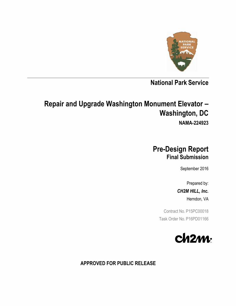
3.04 Mechanical 3.04.1 Maintenance Repairs • The only recommended repair to the
mechanical systems serving the elevator machine room is to replace the Trane PTAC unit. The unit is in poor-to-fair condition (Figure 6) and will need to be replaced within the next 2 to 5 years.
3.04.2 Modernization • It is suggested that, because of the age of the
system, additional testing should be conducted on AHU-1 serving the monument to verify the unit is properly balanced and operating correctly.
3.05 Electrical 3.05.1 Maintenance Repairs
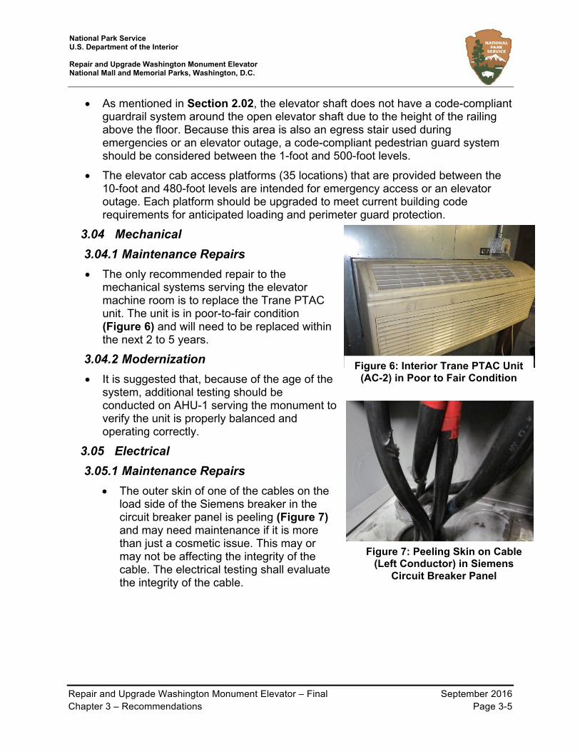
• The outer skin of one of the cables on the load side of the Siemens breaker in the circuit breaker panel is peeling (Figure 7) and may need maintenance if it is more than just a cosmetic issue. This may or may not be affecting the integrity of the cable. The electrical testing shall evaluate the integrity of the cable.
Figure 6: Interior Trane PTAC Unit (AC-2) in Poor to Fair Condition
Figure 7: Peeling Skin on Cable (Left Conductor) in Siemens
Circuit Breaker Panel

National Park Service U.S. Department of the Interior Repair and Upgrade Washington Monument Elevator National Mall and Memorial Parks, Washington, D.C.
Repair and Upgrade Washington Monument Elevator – Final September 2016 Chapter 3 – Recommendations Page 3-6
3.05.2 Modernization • Inside the main circuit breaker panel in the
elevator machine room, the MI conductors (coming from the 480-foot level) transition to copper conductors via splices. After the splices, the copper conductors consist of mismatched sizes (Figure 8): 1 set of 2-250 thousands of circular mils (MCM) cables, and 2 sets of 2-2/O cables. However, per NEC 2011 code, para. 310.10.I.2, parallel conductors should be the same size (2/O and 250 MCM are mismatched). Replacing the cables with all 250 MCM will require re-splicing the MI cable within the panel. While not critical to the performance of the elevator, it is recommended the wiring be upgraded to meet the NEC code. Specifically, the mismatched copper conductors between the MI cable splice and the 400-amp Siemens breaker in the elevator machine room main circuit breaker panel should be the same size and should be sized appropriately.
• Another item to address is the electrical cables associated with the Bunker and the main breakers. The best practice is to size the cables to carry at least 400 amperes. Some of the existing conductors are rated to carry less than 400 amperes (2-2/O cables have a capacity of 350 amperes). However, this is not an NEC code violation and is permissible per NEC para. 240.4.B and 240.6.A, which allow the next highest available breaker size above 350 amperes to be used (400 amperes).
Figure 8: Mismatched Conductor Sizes (250 MCM vs 2/O) in Siemens Circuit
Breaker Panel

National Park Service U.S. Department of the Interior Repair and Upgrade Washington Monument Elevator National Mall and Memorial Parks, Washington, D.C.
Repair and Upgrade Washington Monument Elevator – Final September 2016 Chapter 4 – NPS Project Sustainability Checklist Summary Page 4-1
Chapter 4 – NPS Project Sustainability Checklist Summary
In compliance with NPS’s commitment to sustainability practices, the NPS Project Sustainability Checklist was completed. The checklist, which assists in complying with sustainability standards and is organized around Leadership in Energy and Environmental Design (LEED) credits, was completed to determine how federal sustainability requirements apply to the project. The team worked collaboratively to identify credits that were applicable, as shown in the following chart. The checklist indicates LEED certification is not achievable because not all the prerequisites can be met. A more detailed outline of the Sustainability Checklist and details regarding each potential credit is provided in Appendix E, Project Sustainability Checklist.
SUSTAINABILITY FEATURES PRE-DESIGN Sustainable Site (SS) Maximum LEED NC 2009 Credits: 26
SS Prereq 1 Construction Activity Pollution Prevention Y N/A SS Credit 1 Site Selection Y 1 SS Credit 2 Development Density & Community Connectivity Y 2 SS Credit 3 Brownfield Redevelopment N 0
SS Credit 4.1 Alternative Transportation, Public Transportation Access Y 2
SS Credit 4.2 Alternative Transportation, Bicycle Storage & Changing Rooms N 0
SS Credit 4.3 Alternative Transportation, Low-Emitting & Fuel-Efficient Vehicles N 0
SS Credit 4.4 Alternative Transportation, Parking Capacity Y 1 SS Credit 5.1 Site Development, Protect or Restore Habitat Y 1 SS Credit 5.2 Site Development, Maximize Open Space N 0
SS Credit 6.1 Stormwater Design, Quantity Control (See EISA Section 438) N 0
SS Credit 6.2 Stormwater Design, Quality Control (See EISA Section 438) N 0
EISA 2007, Section 438 Protect Hydrology N N/A
SS Credit 7.1 Heat Island Effect, Non-Roof N 0 SS Credit 7.2 Heat Island Effect, Roof N 0 SS Credit 8 Light Pollution Reduction Y 1
2006 NPS Mgmt Policies (Para. 4.9) Soundscape Preservation Y N/A
2006 NPS Mgmt Policies (Para. 4.10) Dark Sky Preservation NA N/A
Sustainable Sites (SS) Subtotal 8 Water Efficiency (WE) Maximum LEED NC 2009 Credits: 10
WE Prereq 1 Water Use Reduction, 20% Reduction (see Guiding Principle III - Protect and Conserve Water) NA N/A
WE Credit 1 Water Efficient Landscaping, Reduce by 50% (see NA 0

National Park Service U.S. Department of the Interior Repair and Upgrade Washington Monument Elevator National Mall and Memorial Parks, Washington, D.C.
Repair and Upgrade Washington Monument Elevator – Final September 2016 Chapter 4 – NPS Project Sustainability Checklist Summary Page 4-2
SUSTAINABILITY FEATURES PRE-DESIGN Guiding Principle III - Protect and Conserve Water)
WE Credit 1 (cont'd)
Water Efficient Landscaping, No Potable Use or No Irrigation N 0
WE Credit 2 Innovative Wastewater Technologies N 0 NPS Policy Water Metering NA N/A
EPACT 2005, Section 109 Water Used for Energy Conservation NA N/A
WE Credit 3 Water Use Reduction (30%, 35%, 40%) N 0 Water Efficiency (WE) Subtotal 0
Energy & Atmosphere (EA) Maximum LEED NC 2009 Credits: 35
EA Prereq 1 Fundamental Commissioning of the Building Energy Systems * (see Guiding Principle I - Employ Integrated Design Principles)
Y N/A
EA Prereq 2 Minimum Energy Performance (see Guiding Principle II Optimize Energy Performance) NA N/A
EA Prereq 3 Fundamental Refrigerant Management (see Guiding Principle V - Reduce Environmental Impact of Materials) Y N/A
EA Credit 1
Optimize Energy Performance:** (Federal Regulations require 30% for New Construction and 20% for Existing Building Renovation. Note that this automatically equates to 10 Points for New Construction and 7 Points for Existing Building Renovation.) (see Guiding Principle II - Optimize Energy Performance)
NA 0
EISA 2007, Section 433 Reduce Fossil Fuel Derived Energy NA N/A
EO 13423, Sec. 2.(h)
Energy Efficient Electronic Products (Select EPEAT) (Predominantly relates to purchases of desktop/laptop computers and peripherals)
Y N/A
CFR Title 10, Part 436.4 Procure Energy Star or FEMP designated products Y N/A
EPACT 2005, Section 104 Premium Efficiency Electric Motors NA N/A
EISA 2007, Section 523
On-Site Renewable Energy*** Solar Thermal for Hot Water (Choose NA if proven not life cycle cost effective) N N/A
EA Credit 2
On-Site Renewable Energy*** 1%-13% Renewable Energy N 0
EA Credit 3 Enhanced Commissioning (required for projects with building size > 5,000 sf) (see Guiding Principle I - Employ Integrated Design Principles)
NA 0
EA Credit 4 Enhanced Refrigerant Management (see Guiding Principle V - Reduce Environmental Impact of Materials) N 0
EA Credit 5 Measurement & Verification (see Guiding Principle II - Optimize Energy Performance) NA 0
EA Credit 6 Green Power N 0 Energy & Atmosphere (EA) Subtotal 0
Materials & Resources (MR) Maximum LEED NC 2009 Credits: 14 MR Prereq 1 Storage & Collection of Recyclables N N/A MR Credit 1.1 Building Reuse, Maintain Existing Walls, Floors & Roof N 0

National Park Service U.S. Department of the Interior Repair and Upgrade Washington Monument Elevator National Mall and Memorial Parks, Washington, D.C.
Repair and Upgrade Washington Monument Elevator – Final September 2016 Chapter 4 – NPS Project Sustainability Checklist Summary Page 4-3
SUSTAINABILITY FEATURES PRE-DESIGN MR Credit 1.2 Building Reuse, Maintain Interior Nonstructural Elements N 0
MR Credit 2 Construction Waste Management, Divert 50% from Disposal (see Guiding Principle V - Reduce Environmental Impact of Materials)
NA 0
MR Credit 2 (cont'd)
Construction Waste Management, Divert 75% from Disposal N 0
MR Credit 3 Materials Reuse N 0
MR Credit 4 Recycled Content, 10% (post-consumer + ½ pre-consumer). Use EPA's CPG for designated products to use)
N 0
MR Credit 4 Recycled Content, 20% (post-consumer + ½ pre-consumer) N 0
MR Credit 5 Regional Materials, Extracted, Processed & Manufactured Regionally N 0
EO 13423, Sec. 2.(d) Biopreferred Products N N/A
MR Credit 6 Rapidly Renewable Materials N 0
MR Credit 7 Certified Wood (see Guiding Principle V - Reduce Environmental Impact of Materials) NA 0
Materials & Resources (MR) Subtotal 0 Indoor Environmental Quality (EQ) Maximum LEED NC 2009 Credits: 15
EQ Prereq 1 Minimum IAQ Performance (See Guiding Principle IV, Enhance Indoor Environmental Quality) Y N/A
EQ Prereq 2 Environmental Tobacco Smoke (ETS) Control Y N/A EQ Credit 1 Outdoor Air Delivery Monitoring Y 1 EQ Credit 2 Increased Ventilation N 0
EQ Credit 3.1 Construction IAQ Management Plan, During Construction (See Guiding Principle IV, Enhance Indoor Environmental Quality)
Y 1
EQ Credit 3.2 Construction IAQ Management Plan, Before Occupancy (See Guiding Principle IV, Enhance Indoor Environmental Quality)
Y 1
EQ Credit 4.1 Low-Emitting Materials, Adhesives & Sealants (See Guiding Principle IV, Enhance Indoor Environmental Quality)
Y 1
EQ Credit 4.2 Low-Emitting Materials, Paints & Coatings (See Guiding Principle IV, Enhance Indoor Environmental Quality) Y 1
EQ Credit 4.3 Low-Emitting Materials, Flooring Materials (See Guiding Principle IV, Enhance Indoor Environmental Quality) NA 0
EQ Credit 4.4 Low-Emitting Materials, Composite Wood & Agrifiber Products N 0
EQ Credit 5 Indoor Chemical & Pollutant Source Control N 0 MOU Guiding
Principles & EO 13423
Moisture Control NA N/A
EQ Credit 6.1 Controllability of Systems, Lighting (See Guiding Principle IV, Enhance Indoor Environmental Quality) N 0
EQ Credit 6.2 Controllability of Systems, Thermal Comfort N 0

National Park Service U.S. Department of the Interior Repair and Upgrade Washington Monument Elevator National Mall and Memorial Parks, Washington, D.C.
Repair and Upgrade Washington Monument Elevator – Final September 2016 Chapter 4 – NPS Project Sustainability Checklist Summary Page 4-4
SUSTAINABILITY FEATURES PRE-DESIGN
EQ Credit 7.1 Thermal Comfort, Design (See Guiding Principle IV, Enhance Indoor Environmental Quality) Y 1
EQ Credit 7.2 Thermal Comfort, Verification N 0
EQ Credit 8.1 Daylight & Views, Daylight 75% of Spaces (See Guiding Principle IV, Enhance Indoor Environmental Quality) NA 0
EQ Credit 8.2 Daylight & Views, Views for 90% of Spaces N 0 Indoor Environmental Quality (EQ) Subtotal 6
Innovation & Design Process (ID) Maximum LEED NC 2009 Credits: 6 ID Credit 1.1 Innovation in Design: Provide Specific Title
1
ID Credit 1.2 Innovation in Design: Provide Specific Title ID Credit 1.3 Innovation in Design: Provide Specific Title ID Credit 1.4 Innovation in Design: Provide Specific Title ID Credit 1.5 Innovation in Design: Provide Specific Title ID Credit 2 LEED® Accredited Professional Y
Innovation & Design Process (ID) Subtotal 1 Regional Priority (RP) Maximum LEED NC 2009 Credits: 4
RP Credit 1.1 Regional Priority Credit: Region Defined 0 RP Credit 1.2 Regional Priority Credit: Region Defined 0 RP Credit 1.3 Regional Priority Credit: Region Defined 0 RP Credit 1.4 Regional Priority Credit: Region Defined 0
Regional Priority (RP) Subtotal 0 Non-LEED-NC Federal Requirements Maximum LEED NC 2009 Credits: 26
MOU Guiding Principles & EO 13423 (pg. 3)
Complete Integrated Design Narrative During Predesign Only N/A N/A

National Park Service U.S. Department of the Interior Repair and Upgrade Washington Monument Elevator National Mall and Memorial Parks, Washington, D.C.
Repair and Upgrade Washington Monument Elevator – Final September 2016 Appendix A – Operational Integrity Report
Appendix A – Operational Integrity Report

4201 Northview Drive, Suite 314, Bowie, MD 20716 T 301-805-7944 F 301-805-8091 www.lerchbates.com
WASHINGTON MONUMENT WASHINGTON, DC
OPERATIONAL INTEGRITY REPORT
JUNE 24, 2016
ALL DOCUMENTS FURNISHED BY LERCH BATES INC. (LERCH BATES) ARE INSTRUMENTS OF SERVICE AND SHALL REMAIN THE SOLE PROPERTY OF LERCH BATES. LERCH BATES SHALL RETAIN ALL COMMON LAW,
STATUTORY AND OTHER RESERVED RIGHTS, INCLUDING THE COPYRIGHT THERETO. THEY ARE TO BE USED ONLY FOR THIS PROJECT AND ARE NOT TO BE MODIFIED, DISTRIBUTED OR USED FOR ANY OTHER PROJECT, IN WHOLE
OR IN PART, EXCEPT WITH THE WRITTEN AUTHORIZATION OF LERCH BATES. LERCH BATES ACCEPTS NO LIABILITY FOR ANY UNAUTHORIZED USE OR MODIFICATION OF THESE DOCUMENTS.

MAINTENANCE AUDIT SURVEY REPORT
TABLE OF CONTENTS
SECTION I EXECUTIVE SUMMARY ........................................................................................................................... 1 A. GENERAL ........................................................................................................................................................ 1 B. EVALUATION OF MAINTENANCE AND ADJUSTMENT ............................................................................... 1 C. IMMEDIATE ACTION ITEMS ........................................................................................................................... 2 D. CONCLUSION ................................................................................................................................................. 2
SECTION II ADJUSTMENT AND OPERATION OF INDIVIDUAL ELEVATORS ......................................................... 4 A. DISCUSSION ................................................................................................................................................... 4 B. PERFORMANCE CRITERIA ........................................................................................................................... 4 C. ELEVATOR PERFORMANCE EVALUATIONS ............................................................................................... 5
SECTION III MAINTENANCE REVIEW ........................................................................................................................ 6 A. DISCUSSION OF MAINTENANCE AND REPAIR .......................................................................................... 6 B. MAINTENANCE CONTRACTOR DEFICIENCY DESCRIPTION REPORTS ................................................. 7 C. OWNER DEFICIENCY DESCRIPTION REPORTS ........................................................................................ 7 D. SUPPORTING PHOTOGRAPHS .................................................................................................................... 7
SECTION IV RECOMMENDED OWNER IMPROVEMENTS ....................................................................................... 8 A. SHORT TERM UPGRADE RECOMMENDATIONS ........................................................................................ 8 B. LONG TERM UPGRADE RECOMMENDATIONS .......................................................................................... 8
APPENDIX A ELEVATOR PERFORMANCE EVALUATIONS APPENDIX B ELEVATOR MAINTENANCE CONTRACTOR DEFICIENCY REPORTS APPENDIX C OWNER DEFICIENCY REPORTS APPENDIX D SUPPORTING PHOTOGRAPHS

OPERATIONAL INTEGRITY REPORT APPENDIX A
Appendix A-1
SECTION I EXECUTIVE SUMMARY
A. GENERAL
This review was commissioned to evaluate the existing overall condition of the equipment and level of preventive maintenance being provided by Quality Elevator.
A visual review of the physical system components currently in use at the Washington Monument was conducted by David Curtis of Lerch Bates on June 8, 2016 to determine condition, effectiveness of maintenance and code compliance. In addition to the visual review, performance measurements were taken with regard to operation and compared to established Lerch Bates and industry standards. Ride quality was evaluated based on experience with similar installations and compared to Lerch Bates and industry standards.
The results of these tests and all noted deficiencies are specifically delineated within this report.
While we strongly urge you to review the entire report, for your convenience we have summarized our findings within this first section including any items requiring immediate attention of the Maintenance Contractor and/or Property Manager.
B. EVALUATION OF MAINTENANCE AND ADJUSTMENT
For the purpose of evaluating elevator maintenance, Lerch Bates divides the tasks into four general areas: 1) housekeeping, 2) lubrication, 3) replacement or repair of worn components and 4) adjustments. These areas sometimes overlap but are sufficiently independent to allow separate evaluation.
Based on our findings, which we have detailed in the Elevator Maintenance Contractor Deficiency Reports and Performance Evaluations, we rate the current maintenance program as follows:
Elevator(s)
Rating =1 to 5
Meets Requirements
Housekeeping 2 No
Adjustment 3 Yes
Replacement/Repair 2 No
Lubrication 3 Yes
Overall Average 2.5 No
Our evaluation of work is based on the following ratings:
1. A rating of “1” indicates unacceptable levels of maintenance. A concentrated effort on the part of your maintenance contractor is required in all areas in order to justify payment of the monthly contract fee. Approximately 10% of our equipment reviews result in this rating.

OPERATIONAL INTEGRITY REPORT APPENDIX A
Appendix A-2
2. A rating of “2” indicates below average levels of maintenance in most areas. Typically a short term concentrated effort is required by your maintenance contractor to avoid slipping to a “1” rating and or improve to the acceptable rating of 3. Approximately 25% of our equipment review results in this rating.
3. A rating of “3” indicates acceptable levels of maintenance are being provided by your maintenance contractor. However, improvement may be required in specific areas. Approximately 50% of our equipment review results in this rating.
4. A rating of “4” indicates above average levels of maintenance are being provided by your maintenance contractor. This results in very good overall performance and operational characteristics of the equipment with infrequent shutdown of equipment due to maintenance related issues. Approximately 10% of our equipment review results in this rating.
5. A rating of “5” indicates superior levels of maintenance is being provided by your maintenance contractor. We seldom see this rating.
C. IMMEDIATE ACTION ITEMS
1. Contractor Items: The major areas of concern requiring follow-up by the Maintenance Contractor are:
a. Elevators:
1) Due to the controller being custom built and public awareness of this project, we strongly advise the elevator contractor to keep on hand a replacement board for every circuit board in the controller.
2) Elevator hoistway, machine room, cartop and pits require immediate clean down.
3) The worn car sills need to be replaced and car and hoistway door equipment should be reviewed and made to like new condition.
4) Adjust the gap on car doors to a safe distance.
2. Owner Items: The following items require immediate correction but are not the responsibility of the Maintenance Company:
a. Elevators:
1) Repair cab ceiling.
D. CONCLUSION
Our current findings suggest with a thorough clean down of car hoistway and pit along with the replacement of worn car sills and a complete refurbishment and adjusting of car, hoistway and door operating equipment, reliability should improve. However, the car top and hoistway equipment must continue to be reviewed and adjusted on a regular basis in order to keep things running reliably Door issues, along with dust, dirt, and debris are the most common cause of elevator shut downs.
By implementing regular cleaning and adjustments, this should allow improved reliability until the full modernization can be implemented.

OPERATIONAL INTEGRITY REPORT APPENDIX A
Appendix A-3
We recommend that the Maintenance Contractor complete the deficiencies noted within 30 calendar days. For your use, we have attached a list of Owner Recommended Improvements, which are not covered under the Terms and Conditions of your maintenance agreement with your Maintenance Contractor(s) for your use in planning future capital expenditure budgets.
Copies of this report have should be sent to Quality Elevator for their review and action. We have requested that the column entitled “Contractor Completion Date” on the Deficiency Reports be completed prior to July 25, 2016 by the aforementioned contractor(s) and a copy forwarded to you and Lerch Bates for review and file.
This concludes our Report Summary. We trust you find it beneficial in evaluating your ongoing vertical transportation maintenance program. Should you have any questions regarding our review, report, etc., please contact us at your convenience.

OPERATIONAL INTEGRITY REPORT APPENDIX A
Appendix A-4
SECTION II ADJUSTMENT AND OPERATION OF INDIVIDUAL ELEVATORS
A. DISCUSSION
This section covers the factors associated with the operation of specific elements of the elevator system against standards which have been established either by Code, established Lerch Bates standards, or standards common to the elevator industry.
Operating efficiency of elevator groups is a combination of the efficiency of each elevator traveling from floor to floor loading and discharging passengers, and the effectiveness of the group control regulating the dispatch and spacing of elevators to meet traffic demand. Improper adjustment may reduce performance and lengthen response times 10% to 15%.
The criterion used to evaluate the performance measured on each elevator is defined below in Item B.
B. PERFORMANCE CRITERIA
1. Elevator Speed: Elevator speed is measured with a tachometer while the elevator makes a full run through the hoistway with no load in the car. Contract speed (to be found on the governor rating plate or the cross head on the car) should be maintained within criteria range indicated on individual performance evaluations under any load condition or travel direction.
2. Door Open Time: Measured from the instant the doors begin to open until the doors are fully open.
Door opening time should be as fast as possible to provide optimum adjustment of efficient elevator service. Our recommended door times are based on the door operator equipment installed while providing smooth operation and long equipment life.
3. Door Closing Time: Measured from the instant the doors begin to close until the doors are fully closed. The ASME A17.1 Code limits door closing time by defining the level of kinetic energy generated during door closing operation. We indicate the closing time, which approximates Code requirement based on average door weight.
4. Interrupted Ray Door Time: Initially measured from the instant the doors reach the fully open position until the doors begin to close after interrupting the door protective devices while doors are opening. Subsequently measured upon re-interrupting the door protective devices.
5. Door Closing Force: Measured with a spring pressure gauge as the doors begin to close. The measured value is the force required to prevent the doors from closing under power. ASME A17.1 Code requires that the force required to stall the closing door be no more than 30 force pounds.
6. Operation: Subjective evaluation of the quality of ride and door operation. The factors identified are: Acceleration Up, Acceleration Down, Deceleration Up, Deceleration Down, Elevator Stop, Door Open and Door Close.
7. Safety: The items listed (car door protective devices, car stop switch and alarm bell for the car) are those normally found on most elevators. We check them to make certain they are functioning properly.

OPERATIONAL INTEGRITY REPORT APPENDIX A
Appendix A-5
C. ELEVATOR PERFORMANCE EVALUATIONS
The Performance Evaluations in Appendix A (see page 9) tabulate the results of our survey based on the criteria outlined in Item B above. Items marked “NO” in the Meets Criteria column require adjustments/correction to ensure optimal performance and/or satisfy regulation and code requirements.

OPERATIONAL INTEGRITY REPORT APPENDIX A
Appendix A-6
SECTION III MAINTENANCE REVIEW
A. DISCUSSION OF MAINTENANCE AND REPAIR
Elevator maintenance can be broken into four general areas; housekeeping, lubrication, renewal or repair of worn components, and adjustments. These areas sometimes overlap but are sufficiently independent to allow separate evaluation.
1. Housekeeping
Housekeeping requires about 60% of the total time spent maintaining equipment. While at first glance, this would appear to be an excessive amount of time simply cleaning, it is time well spent. If a job is kept clean, the fire hazard (especially in hoistways) is lessened. Potential troubles and worn components are often detected during routine cleaning operations. Dirt is a major cause of elevator malfunction; a speck of dust between relay contacts can shut a unit down. Finally, a clean job makes routine inspection and maintenance easier.
a. Summary of Survey Results:
1) Clean machine room
2) Clean hoist machine
3) Clean governor
4) Clean out controller
5) Clean down hoistway
6) Clean cartop
7) Clean pit
2. Lubrication
Lubrication requires about 15% of the total time spent maintaining equipment. As with any mechanical equipment, proper lubrication minimizes wear, assures proper operation and lengthens trouble-free life of components.
a. Summary of Survey Results:
1) None at this time
3. Replacement and Repair
Replacement or repair of worn components represents about 15% of elevator maintenance. By detecting and replacing worn components, it is often possible to prevent elevator malfunction and unscheduled shutdown. Systematic repair and replacement of components ensures optimum useful life of the elevator.

OPERATIONAL INTEGRITY REPORT APPENDIX A
Appendix A-7
a. Summary of Survey Results:
1) Repair worn car sills, worn car, and hoistway door equipment.
2) Keep an extra set of controller boards on hand
4. Adjustments
Adjustments require about 10% of elevator maintenance time. Proper, timely adjustment keeps the equipment working smoothly and quietly.
a. Summary of Survey Results
1) Due to the extreme use of this elevator the doors need to be regularly adjusted
B. MAINTENANCE CONTRACTOR DEFICIENCY DESCRIPTION REPORTS
The items noted in the Elevator Maintenance Contractor Deficiency Reports require correction by the Maintenance Contractor to ensure optimum equipment reliability and performance.
C. OWNER DEFICIENCY DESCRIPTION REPORTS
The items noted in the Owner Deficiency Reports for elevators require correction to ensure optimum equipment reliability, performance and maintenance personnel safety. All of the items listed are not covered under the terms of the maintenance agreement and are, therefore, the responsibility of the Owner.
D. SUPPORTING PHOTOGRAPHS
See Appendix D

OPERATIONAL INTEGRITY REPORT APPENDIX A
Appendix A-8
SECTION IV RECOMMENDED OWNER IMPROVEMENTS
The following items represent short (maintenance) and long-term (modernization) upgrade recommendations. Short-term upgrades are recommended to be accomplished within 3 months; long-term upgrades are recommended to be accomplished within 1 to 2 years.
A. SHORT TERM UPGRADE RECOMMENDATIONS
1. Replace worn car sills and completely go through the car and hoistway door operating equipment.
B. LONG TERM UPGRADE RECOMMENDATIONS
1. Enclose hoistway where possible to limit volume of dust and debris on elevator equipment and improve safety of existing passengers using stairs.

OPERATIONAL INTEGRITY REPORT APPENDIX A
Appendix A-9
APPENDIX A
ELEVATOR PERFORMANCE EVALUATIONS

OPERATIONAL INTEGRITY REPORT APPENDIX A
Appendix A-10
PROJECT NAME: WASHINGTON MONUMENT OWNER ID NO.: ELEVATOR NO.: 1 REVIEW DATE: 6-8-16
PROJECT LOCATION: 2 15TH STREET NW PERMIT ID NO.: ELEVATOR GROUP:
CITY AND STATE: WASHINGTON DC MACHINE TYPE: GEARLESS
LB PROJECT NUMBER: 0100010124 ELEVATOR TYPE: PASSANGER
MANUFACTURER (OEM): OTIS FLOORS SERVED: G, 2 - 3 FRONT: 2 REAR: 2
CONTRACTOR: QUALITY CAPACITY: 6,800 LBS. CONTRACT SPEED: 500 FPM
DATE OF INSTALLATION: 1957 SAFETY TESTS: ANNUAL TEST 5 YEAR TEST
YES NO YES NO
DATE COMPLETED DATE COMPLETED 12/2012 DATE OF MODIFICATION: 1997
ELEVATOR INFORMATION
DOOR OPERATOR SPEED: MEDIUM DOOR TYPE: TWO SPEED CENTER OPENING DOOR WIDTH: 4’ – 0” AND HEIGHT: 7’ – 0” PRE-OPENING: NO
MEASURED CAR EMPTY TARGET CRITERIA MEETS CRITERIA COMMENTS
SPEED UP 6 3% 492 FPM 500 FPM YES SPEED DOWN 6 3% 493 FPM 500 FPM YES STOPPING ZONE 61/4” 61/4” YES MEASURED FRONT REAR CRITERIA FRONT / REAR MEETS CRITERIA COMMENTS DOOR OPEN 2.6 SEC 1.8 SEC 1.8 SEC 1.8 SEC NO/YES DOOR CLOSE 2.4 SEC 2.3 SEC 2.7 SEC 2.7 SEC YES/YES INTERRUPTED RAY HOLD OPEN *>3.0 INITIAL, .5-1.5 SUBSEQUENT .5 SEC .8 SEC >3.0* SEC >3.0* SEC NO
EXTENDED DOOR CLOSE TIME NUDGING) 1.68 X LB MINIMUM DOOR CLOSE TIME
4.0 SEC 3.8 SEC 4.5 SEC 4.5 SEC. YES
STALL PRESSURE 25 LBS. 25 LBS. 30 MAX 30 MAX YES
OBSERVATIONS MEETS CRITERIA COMMENTS FEATURES INSTALLED TESTED COMMENTS
ACCELERATION YES EMERGENCY LIGHT YES NO RIDE YES FIRE SERVICE PH1 YES NO DECELERATION YES FIRE SERVICE PH2 YES NO STOP YES FIRE PHONE JACK YES NO DOOR OPERATION YES STANDBY POWER NO DOOR PROTECTION YES TELEPHONE YES YES DOOR OPEN BUTTON YES INTERCOM N/A ALARM BUTTON YES STOP SWITCH NO CAR LIGHTING GUARDED YES SEISMIC SENSOR YES NO FALSE CALL CANCEL N/A DOOR RESTRICTION YES ADDITIONAL COMMENTS:

OPERATIONAL INTEGRITY REPORT APPENDIX C
APPENDIX B
ELEVATOR MAINTENANCE CONTRACTOR
DEFICIENCY REPORTS

OPERATIONAL INTEGRITY REPORT APPENDIX C
ELEVATOR DEFICIENCY REPORT ORIGINAL REVIEW DATE: JUNE 8, 2016
UPDATED AUGUST 30, 2016 UPDATED SEPTEMBER 13, 2016
CONTRACTOR
ELEVATOR NO. 1 CONTRACTOR
COMPLETION DATE
COMPLETED
BY
LERCH BATES
VERIFIED ESTIMATED ACTUAL
ITEM NO. MACHINE ROOM
1 CLEAN MACHINE ROOM 30 DAYS 9/13/16 DC COMPLETED
2 CLEAN HOIST MACHINE INSIDE AND OUT OF ACCUMULATION OF DIRT 30 DAYS
3 CLEAN GOVERNOR OF ACCUMULATION OF DIRT AND LUBRICATE 30 DAYS 9/13/16 DC COMPLETED
4 CLEAN OUT CONTROLLER 30 DAYS 9/13/16 DC COMPLETED
5 INSPECT AND FIX LEAKING MOTOR BEARINGS 30 DAYS 6 FIX GREENFIELD WIRING CONNECTING TO TOP OF MOTOR 30 DAYS ITEM NO. HOISTWAY
1 REVIEW AND ADJUST/REPAIR HOISTWAY DOOR EQUIPMENT 30 DAYS 9/13/16 DC
COMPLETED BUT NEEDS TO BE
DONE QUARTERLY
2 REVIEW AND ADJUST/REPAIR BOTH FRONT AND REAR CAR DOOR OPERATING EQUIPMENT
30 DAYS 9/13/16 DC COMPLETED
3 ADJUST HOISTWAY DOORS (FRONT AND REAR) AT THE GROUND FLOOR TO REDUCE SIZE OF GAP AT BOTTOM
30 DAYS 9/13/16 DC COMPLETED
4 CLEAN DOWN HOISTWAY (INCLUDING STAIRS, MESH, LEDGES, PIPING, BEAMS, ETC.) .CLEAN CARTOP SHEAVE AND OVERHEAD DEFLECTOR SHEAVE, CHECK SEALS AND LUBRICATE. CLEANDOWN NEEDS TO BE SCHEDULED YEARLY AND COORDINATED TO HAPPEN IN UNISON WITH CLEANDOWN OF STAIRS
30 DAYS
5 CLEAN CARTOP 30 DAYS 9/13/16 DC COMPLETED
6 CARTOP LIGHT NEEDS TO BE OPERATIONAL 30 DAYS 9/13/16 DC COMPLETED
7 REPLACE MISSING DUST COVERS 30 DAYS 9/13/16 DC COMPLETED
8 CONFIRM THE TRAVELING CABLES DO NOT HAVE SHORTS IN THE WIRES AS THERE IS TAPE ON THE TRAVELING CABLE AT THE TOP AND BOTTOM OF THE HOISTWAY
30 DAYS 9/13/16 DC
COMPLETED
ITEM NO. PIT
1 CLEAN PIT 30 DAYS 9/13/16 DC COMPLETED
2 ELECTRICAL CONDUIT IN THE PIT APPEARS TO BE CORRODED WITH CONDUIT TO THE COUNTERWEIGHT BUFFER SWITCH BEING THE WORST. CONDUIT IN THE PIT NEEDS TO BE MONITORED AND WATER LEAKAGE IN PIT ELIMINATED.
30 DAYS
ITEM NO. CAR ENCLOSURE
1 REDUCE GAP BETWEEN REAR DOOR AND RETURN PANEL 30 DAYS 9/13/16 DC COMPLETED
2 SAND CAB SILLS WITH 800 GRIT SAND PAPER TO REMOVE GOUGES 30 DAYS
3 CLEAN DEBRIS FROM INSIDE AND OUTSIDE THE CAB 30 DAYS 9/13/16 DC COMPLETED

OPERATIONAL INTEGRITY REPORT APPENDIX C
ITEM NO. REQUIRED TESTING
1 PROVIDE DOCUMENTATION AND TAG OF ANNUAL NO LOAD TEST
30 DAYS
ITEM NO. PERFORMANCE 1 ADJUST THE INTERRUPTED RAY TIME (TIME DOORS REMAIN OPEN AFTER
THE RAYS HAVE BEEN INTERRUPTED) TO INITIAL TIME OF >3.0 SECONDS 30 DAYS COMPLETED

OPERATIONAL INTEGRITY REPORT APPENDIX C
APPENDIX C
OWNER
DEFICIENCY REPORTS

OPERATIONAL INTEGRITY REPORT APPENDIX C
ELEVATOR DEFICIENCY REPORT ORIGINAL REVIEW DATE: JUNE 8, 2016
UPDATED AUGUST 30, 2016 UPDATED SEPTEMBER 13, 2016
OWNER
ELEVATOR NO. 1 OWNER
COMPLETION DATE COMPLETED
BY
LERCH BATES
VERIFIED ESTIMATED ACTUAL
ITEM NO. MACHINE ROOM
1 PROVIDE COVERS ON VENT IN MACHINE ROOM/AIR REGISTER (WE SUGGEST A FILTER BE INSTALLED TO REDUCE THE AMOUNT OF DUST BEING BLOWN ON THE HOIST MACHINE.)
30 DAYS
2 FIX GREENFIELD WIRING CONNECTING TO TOP OF MOTOR 30 DAYS
ITEM NO. HOISTWAY 1 PROVIDE CONDUIT FOR CCTV CAMERA ON CARTOP 30 DAYS 2 REPLACE MISSING ELECTRICAL COVER ON JUNCTION BOX FOR
CCTV CAMERA 30 DAYS
3 CLEAN INSIDE/OUTSIDE OF OBSERVATION GLASS LOCATED AT 280’, 270’, 140’ AND 130’
30 DAYS
ITEM NO. PIT
1 ELEVATOR PIT WAS WET. WATER APPEARS TO HAVE ENTERED THE PIT ON MULTIPLE OCCASIONS CAUSING CORROSION OF ELECTRICAL BOXES AND CONDUIT. WHILE ON SITE, WATER WAS LEAKING OVER ELECTRICAL CONDUIT AND ELECTRICAL BOXES. THE COUNTERWEIGHT BUFFER SWITCH CONDUIT APPEARED TO BE IN THE WORST SHAPE AND ELEVATOR CONTRACTOR HAS BEEN REQUESTED TO MONITOR. WATER LEAKAGE IN PIT MUST BE ELIMINATED.
ITEM NO. CAR ENCLOSURE
1 REPAIR CEILING WHERE A PORTION APPEARS TO BE COMING LOOSE 30 DAYS COMPLETED

OPERATIONAL INTEGRITY REPORT APPENDIX D
APPENDIX D
SUPPORTING PHOTOGRAPHS

OPERATIONAL INTEGRITY REPORT APPENDIX D
1. Clean Machine Room 2. Clean hoist machine of accumulation of dirt
3. Clean hoist machine of accumulation of dirt 4. Clean out controller
OPERATIONAL INTEGRITY REPORT APPENDIX D
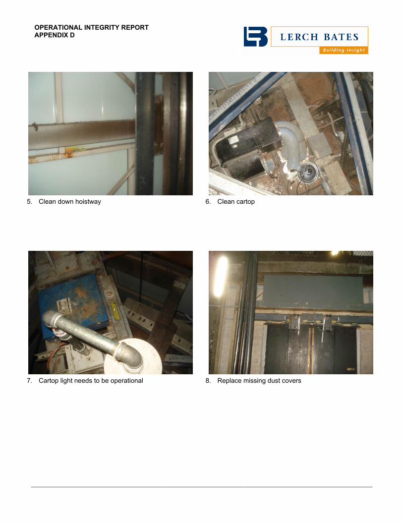
5. Clean down hoistway 6. Clean cartop
7. Cartop light needs to be operational 8. Replace missing dust covers

OPERATIONAL INTEGRITY REPORT APPENDIX D
9. Confirm the traveling cables do not have shorts in the
wires as there is tape on the traveling cable at the top and bottom of the hoistway
10. Clean pit
11. Reduce gap between rear door and return panel 12. Car sill is worn and requires replacement

OPERATIONAL INTEGRITY REPORT APPENDIX D
13. Replace electrical cover on cartop fan and clean
cartop 14. Provide covers on A/C vent
15. It is recommended that during the modernization, all
CCTV wiring be placed in conduit. 16. Replace missing electrical cover on junction box for
CCTV camera at cartop

OPERATIONAL INTEGRITY REPORT APPENDIX D
17. Repair ceiling where a portion appears to be coming
loose 18. Remove dumbells from machine room. By code, only
elevator equipment is allowed in machine room.
19. Repair position indicator in machine room 20. Repair position indicator in fire control room at ground
floor

OPERATIONAL INTEGRITY REPORT APPENDIX D
21. Clean hoistway outside of dust, dirt and debris 22. Clean inside hoistway of dust, dirt and debris
23. Chain link fence around hoistway is not safe or code compliant
24. All wiring on car top should be protected

OPERATIONAL INTEGRITY REPORT APPENDIX D
25. All wiring on car top should be protected.

National Park Service U.S. Department of the Interior Repair and Upgrade Washington Monument Elevator National Mall and Memorial Parks, Washington, D.C.
Repair and Upgrade Washington Monument Elevator – Final September 2016 Appendix B – Project Upgrade Repair Program
Appendix B – Project Upgrade Repair Program

PROJECT UPGRADE REPAIR PROGRAM APPENDIX B
2
1. Control System: Motion Controllers (Current control system is MCE, Date: 3/4/1998). New electronic components will be designed and installed to provide a more reliable operation of the elevator and its movement.
Selective Collective Microprocessor-Based: Operate car without attendant from pushbuttons in car and located at each floor. When car is available, automatically start car and dispatch it to floor corresponding to registered car or hall call. Once car starts, respond to registered calls in direction of travel and in the order the floors are reached.
Do not reverse car direction until all car calls have been answered, or until all hall calls ahead of car and corresponding to the direction of car travel have been answered.
Slow car and stop automatically at floors corresponding to registered calls, in the order in which they are approached in either direction of travel. As slowdown is initiated for a hall call, automatically cancel hall call. Cancel car calls in the same manner. Hold car at arrival floor an adjustable time interval to allow passenger transfer.
Answer calls corresponding to direction in which car is traveling unless call in the opposite direction is highest (or lowest) call registered.
Illuminate appropriate pushbutton to indicate call registration. Extinguish light when call is answered.
Approved microprocessor-based, group dispatch, car and motion control systems as follows: KONE: Resolve Otis: Elevonic Schindler: Miconic TXR5 ThyssenKrupp: TAC 32-T Elevator Controls Corp: G900-XL MCE: icontrols Swift: Futura
Optional Dispatch: Approved microprocessor-based, dispatch with Destination Dispatch and motion control systems as follows: KONE: Resolve w/AI with Destination Dispatch Otis Elevonic: Compass Schindler: Miconic 10 ThyssenKrupp: TAC 32-T w/Destination Dispatch MCE: i w/AI w/Destination Dispatch Swift: Futura w/Destination Dispatch
Include, as a minimum, the following features: Register service calls from pushbuttons located at each floor. Slow cars and stop automatically at floors corresponding to registered calls. Make stops at successive floors for each direction of travel irrespective of order. Simultaneous to initiation of slow

PROJECT UPGRADE REPAIR PROGRAM APPENDIX B
3
down of a car for a hall call, cancel that call. Render hall pushbutton ineffective until car doors begin to close after passenger transfer. Hall lantern shall sound again and illumination shall pulse just prior to car arrival. Accomplish car direction reversal without closing and reopening doors. Use easily reprogrammable system software. Provide manual means to force a stop at the main floor when passing to or from lower levels. Required Features:
Special exhibit operation – Car lights and runs at a reduced speed.
Dispatch Protection: Backup dispatching shall function in the same manner as the prima0yr dispatching.
Position Sensing: Update car position when passing or stopping at each landing.
Hall Pushbutton Failure: Provide multiple power sources and separate fusing for pushbutton risers.
This new motion controller will be a non-proprietary system. Consideration should be given to locating this equipment in the old mg room. Please confirm if this space is still available and no other equipment has been used for this equipment.
2. Machines and Brakes
Gearless Traction Hoist Machine: Retain existing.
Restore, clean and paint to function and appear in like new condition.
Drain, flush and provide new machine lubricant.
Replace worn bearings.
Provide supplemental rope and sheave guards as required.
Retrofit new direct drive, digital, closed-loop velocity encoder on hoist machine.
Clean and true motor commutator. Provide new commutator brushes.
Other work deemed required to provide “like new” operation. Like new refers to the parts (existing machine and brake in this case) being refurbished to like new condition (original specs).
Completely disassemble, clean, and inspect all brake components. Replace all worn or damaged parts. Reassemble and test for proper operation.
Emergency Brake:

PROJECT UPGRADE REPAIR PROGRAM APPENDIX B
4
Provide means to prevent ascending car over-speed and unintended car movement per Code.
Acceptable emergency brake devices:
BODE Rope Brake
Hollister-Whitney Rope Gripper
Mount the auxiliary brake on suitable structural steel supports. Provide a drawing showing the supports, stamped by Professional Engineer verifying the adequacy of the support provided.
Provide control circuits to enable the device to function as required by Code.
3. Cab Door Equipment and Operators: Replacement of the cab and hoistway door equipment operator will reduce the amount of failed sensor readings which currently shut down the operation of the elevator. The proposed scope of work is as follows:
Entrance Equipment:
Door Hangers: Two-point hanger roller with neoprene roller surface and suspension with eccentric upthrust roller adjustment.
Door Tracks: Bar or formed, cold-drawn removable steel tracks with smooth roller contact surface.
Door Interlocks: Operable without retiring cam. Paint interlock box flat black.
Door Closers: Spring, spirator, or jamb/strut mounted counterweight type. Design and adjust to insure smooth, quiet mechanical close of doors.
Hoistway Door Unlocking Device: Provide unlocking device with escutcheon in door panel at all floors, with finish to match adjacent surface.
Hoistway Access Switches: Mount in wall at top and bottom floors. Provide switch with faceplate.
Door Clutch: Heavy-duty clutch, linkage arms, drive blocks and pickup rollers or cams to provide positive, smooth, quiet door operation. Design clutch so car doors can be closed, while hoistway doors remain open.
Restricted Opening Device: Restrict opening of car door(s) outside unlocking zone. Plunger type restrictors not acceptable.
Door Operator: High speed, heavy-duty door operator capable of opening doors at no less than 2-1/2 f.p.s. Accomplish reversal in no more than 2-1/2" of door movement.

PROJECT UPGRADE REPAIR PROGRAM APPENDIX B
5
Provide solid-state door control with closed loop circuitry to constantly monitor and automatically adjust door operation based upon velocity, position, and motor current. Maintain consistent, smooth, and quiet door operation at all floors, regardless of door weight or varying air pressure. Acceptable closed-loop door operators:
KONE AMD 2.0
Otis i Motion II (Geared)
Schindler QKS 15 Heavy Duty
ThyssenKrupp HD91 StarTrac
G.A.L. MOVFR
Door Control Device:
Infrared Reopening Device: Black fully enclosed device with full screen infrared matrix or multiple beams extending vertically along leading edge of each door panel to minimum height of 7'-0" above finished floor. Provide extension of housing and lens. Device shall prevent doors from closing and reverse doors at normal opening speed if beams are obstructed while doors are closing, except during nudging operation. In event of device failure, provide for automatic shutdown of car at floor level with doors open
Acceptable Infrared Reopening Device:
Cegard/MAX-154 by CEDES
Gatekeeper by Adams
Lambda II by Otis
Magic Edge by Tri-Tronics
Microlite by ThyssenKrupp
Microscan E by T.L. Jones
Pana40 Plus by Janus
Door pressure elements need to be explored, as occupants press against doors. This current equipment is over 11 years old and beyond its lifecycle. Cadmium plated car and hoistway door equipment is recommended.

PROJECT UPGRADE REPAIR PROGRAM APPENDIX B
6
4. Safety Device: Retain existing. Check and tighten all fastenings. Disassemble, clean, and inspect components. Replace all worn or damaged parts. Reassemble and test for proper operation.
5. Buffer Switch and Leveling Unit Indicator: New buffer switch indicator in the pit, which activates prior to the counterweight system activating, will allow for a scheduled shortening of the hoist ropes and prevent a premature shut down of the elevator.
6. New Cab Top Lighting: Design replacement cab top lighting system with energy efficient lighting and produces low glare as not to affect security cameras and to improve illumination of commemorative stones in shaft. Add GFCI outlet.
7. Digital Video Display: Provide digital, wireless, flat panel active matrix video display screen in each car front return panel. Provide site programmable, system control unit, upload interface, antenna, and all required monitoring hardware, shielded wiring or fibre optic cabling and power source wiring, etc. Program the current monument’s protocol used by the Rangers. Coordinate installation details, including required cut-outs and video display mounting provisions in car front return panel(s). Provide “15" video display unit.
8. Pushbuttons: Provide 1 riser with flush mounted faceplates. Include pushbuttons for each direction of travel which illuminate to indicate call registration. Include approved engraved message and pictorial representation prohibiting use of elevator during fire or other emergency situation as part of faceplate. Pushbutton design shall match car operating panel pushbuttons. Provide vandal resistant pushbutton and light assemblies. Provide enlarged faceplate to cover existing wall blockout and facilitate handicapped access requirements. Provide any cutting and patching required. Provide an illuminated signal marked "Elevator Emergency Power" to indicate emergency or standby power is in effect.
Hall Lanterns: Provide at each entrance to indicate travel direction of arriving car. Locate as detailed on architectural drawings. Illuminate up or down LED lights and sound tone once for up and twice for down direction prior to car arrival at floor. Sound level shall be adjustable from 20-80 dBA measured at 5''-0" in front of hall control station and 3'-0" off floor. Illuminate light until the car doors start to close. Provide advanced predictive hall lantern notification to comply with ADA hall call notification time. Car direction lenses shall be arrow shaped with faceplates. Lenses shall be minimum 2-1/2" in their smallest dimension. Provide vandal resistant lantern and light assemblies consisting of series of dots or lines for maximum visibility.
Security Control Panel: Provide a control panel and color SVGA with the capability to activate, display, monitor, or control the following functions.

PROJECT UPGRADE REPAIR PROGRAM APPENDIX B
7
On/off means to place car in or out of service. When placed in “off” position return car(s) nonstop to designated floor and park with door(s) open for adjustable period of 1-3 minutes. At expiration of time, restore car to service.
Car operating on normal/standby power.
Car position and direction of travel.
Car calls.
Hall calls.
Operating mode.
Door status.
Delayed car.
Load weighing and by-pass.
Car to lobby feature.
Car in/out of service.
Seismic operation.
Secured floor control and code entry.
Alarm distress signal.
Card reader override. Individual car on/off provisions.
Fixtures and monitor shall be located as directed by Architect. Where applicable, identify all indicators and manual switches with appropriate engraving. Provide conduit and wiring to control panel. Coordinate size and location with Building Console Supplier.
9. Machine Room Access: To address accessibility and safety/access issues for the machine room located 19’ above 500’ observation level, a new ladder access with platform will need to be designed and installed. Currently there is a temporary aluminum ladder anchored to the structure. A new ladder will provide compliant, safer means to access the machine room space and be sympathetic to the resource. An access protocol needs to be provided as part of this system.
10. Remote Diagnostic System at 0-foot level: Specify a remote control system to allow the diagnostics and operation of the elevator for both normal and emergency situations. This will be able to access the system as found in the 519’ level. System should allow complete control of elevator as well as troubleshooting capabilities.

PROJECT UPGRADE REPAIR PROGRAM APPENDIX B
8
11. Compensation and Hoist Ropes: Study reliability of existing ropes. Recommend and
specify any adjustments. Also, check MI cables.
12. Elevator Inspection Key Switch: Replacement of the inspection switch would regain the Park Service’s control over the key switch that has been widely distributed. Analyze and recommend adjustments to cab control panel to minimize or eliminate the need for traditional keys (smartcard, ID’s, etc.).
13. Seismic Operations and Equipment: Include provisions to tie in to the existing seismic sensor.
14. Electrical: Analyze and prepare repair plan, as needed, to electrical system from the main breaker to the main drives in the machine room; to include all power supplies.
15. Machine Room Ventilation: Evaluate HVAC unit(s) in machine room and prepare documents to address any ventilation deficiencies. Evaluate whether the building HVAC system that feeds the machine room and elevator shaft is anyway contributing to failures.
16. Cab Ventilation: Explore options for improved ventilation control and effectiveness. Providing HVAC on the elevator could improve temperature in car.
17. Evaluate and make recommendations for cab phone/communication device to allow for more effective communication between operators and on-site staff at the ground level. Installation of an intercom system that allows immediate, reliable communication between the US Park Police booth at the bottom of the monument, the control room(s), and the elevator cab. It appears that the Motorolla communication system used by National Park Police may interfere with controls so an on site intercom may work better. Intercom and Distress Signal System
General: Provide intercommunication system. Include all wiring between elevator hoistways and control panels. Include the following stations:
Station Location Type Station Selection Buttons to Call
Elevator Machine Room Master Control Panels
Security Control Panel Master Machine Rooms

PROJECT UPGRADE REPAIR PROGRAM APPENDIX B
9
Firefighters’ Control Panel Master Machine Rooms
Elevator Remote Lobby Control Panel
Basic Equipment:
Amplifier providing static-free voice transmission with adequate volume and minimum distortion at all stations, with pre-amplifier capable of receiving voice and music inputs from building and emergency building communication system.
Activation of emergency building communication system overrides all other conversations and permits one-way conversation to all master stations in system.
Master Stations:
Speaker-microphone combination, and/or handset for two-way communication.
Selection buttons to enable communication with all master stations. Maintain continual reception of hands-free reply from station when a selected button is depressed.
Two-Position “Talk/Listen” Button: Press to talk; release to listen.
Illuminate “in use” light when any master station is being used.
Reset button to make system available for use by any master station.
Volume control knob for adjustment of incoming volume.
Button to establish communications with all stations.
Distress light in lobby panel which illuminates when “push to call” button or alarm button in car is actuated. Energize distress light and buzzer or chime until intercom selection button for that car has been depressed. Sound buzzer or chime in lobby panel simultaneously with illumination of distress light.
Remote Stations:
Station in car shall be activated by “push to call” two-way communication button. “Push to call” button shall illuminate and flash when call is acknowledged. Button shall match car operating panel pushbutton design. Provide uppercase “PUSH TO CALL,” “HELP ON THE WAY” engraved signage adjacent to button. Provide “push to call” button tactile symbol, engraved signage, and Braille adjacent to button.

PROJECT UPGRADE REPAIR PROGRAM APPENDIX B
10
Locate car microphone and speaker, or transceiver/speaker combination in car canopy behind front return panel with drilled speaker pattern, with shielded wiring to machine room junction box.
Station Housings:
House master station in machine room in a metal compartment with baked enamel finish. Attach to the group elevator supervisory control panel or wall mount. Provide communication handset with 25'-0" long cord.
Provide control center master intercoms with stainless steel satin finish faceplates and engraved operating instructions. Coordinate faceplate size and installation of units with building Console Supplier.
18. Evaluate and make recommendations for cab operator options to include ways to expedite descent in case of passenger needs. It appears that Destination type control system may be able to provide the level of service desired and eliminate the need for buttons in the car.

National Park Service U.S. Department of the Interior Repair and Upgrade Washington Monument Elevator National Mall and Memorial Parks, Washington, D.C.
Repair and Upgrade Washington Monument Elevator – Final September 2016 Appendix C – Elevator Machine Test Report
Appendix C – Elevator Machine Test Report


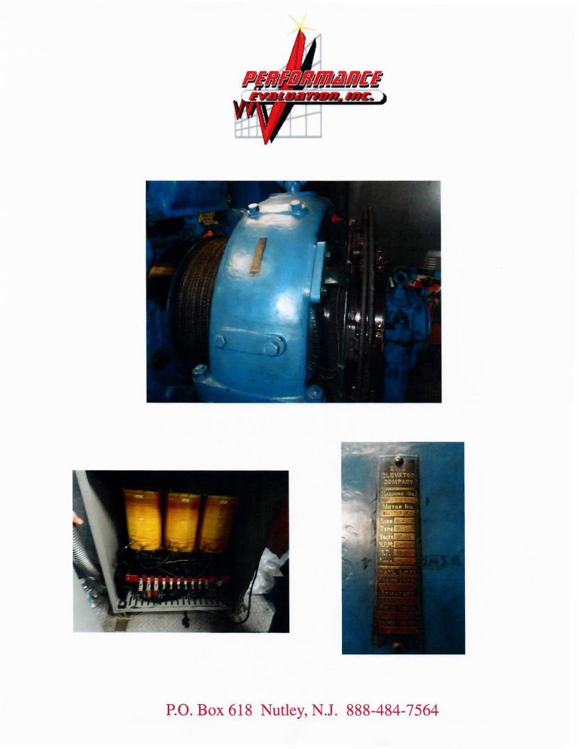


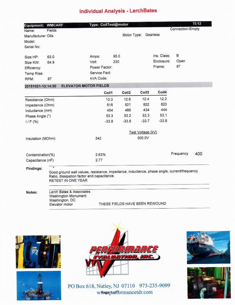


National Park Service U.S. Department of the Interior Repair and Upgrade Washington Monument Elevator National Mall and Memorial Parks, Washington, D.C.
Repair and Upgrade Washington Monument Elevator – Final September 2016 Appendix D – Elevator Modernization Study
Appendix D – Elevator Modernization Study

4201 Northview Drive, Suite 314, Bowie, MD 20716 T 301.805.7944 F 301.805.8091 www.lerchbates.com
WASHINGTON MONUMENT ELEVATOR WASHINGTON, DC
DRAFT ELEVATOR MODERNIZATION SURVEY
MAY 27, 2016
ALL DOCUMENTS FURNISHED BY LERCH BATES INC. (LERCH BATES) ARE INSTRUMENTS OF SERVICE AND SHALL REMAIN THE SOLE PROPERTY OF LERCH BATES. LERCH BATES SHALL RETAIN ALL COMMON LAW,
STATUTORY AND OTHER RESERVED RIGHTS, INCLUDING THE COPYRIGHT THERETO. THEY ARE TO BE USED ONLY FOR THIS PROJECT AND ARE NOT TO BE MODIFIED, DISTRIBUTED OR USED FOR ANY OTHER PROJECT, IN WHOLE
OR IN PART, EXCEPT WITH THE WRITTEN AUTHORIZATION OF LERCH BATES. LERCH BATES ACCEPTS NO LIABILITY FOR ANY UNAUTHORIZED USE OR MODIFICATION OF THESE DOCUMENTS.

ELEVATOR MODERNIZATION SURVEY
TABLE OF CONTENTS
SECTION 1 EXECUTIVE SUMMARY AND RECOMMENDATIONS ........................................................... 1
A. GENERAL ...................................................................................................................................... 1
B. MODERNIZATION OBJECTIVES .................................................................................................. 1
C. CONCLUSION ................................................................................................................................ 1
D. RECOMMENDATIONS .................................................................................................................. 2
SECTION 2 EXISTING EQUIPMENT REVIEW ............................................................................................ 3
A. GENERAL ...................................................................................................................................... 3
B. DISCUSSION ................................................................................................................................. 3
C. EQUIPMENT DISPOSITION .......................................................................................................... 3
SECTION 3 CODE RELATED ITEMS .......................................................................................................... 6
A. GENERAL ...................................................................................................................................... 6
B. CONCLUSIONS ............................................................................................................................. 6
SECTION 4 MODERNIZATION PLANS ....................................................................................................... 7
A. GENERAL ...................................................................................................................................... 7
B. MODERNIZATION SCOPE ............................................................................................................ 7
C. RECOMMENDATIONS .................................................................................................................. 8
APPENDIX A SUPPORTING PHOTOGRAPHS ....................................................................................... 10

ELEVATOR MODERNIZATION SURVEY
Washington Monument Elevator, Washington, DC Lerch Bates Project No. R0100010124 © 2010 Lerch Bates Inc.
May 27, 2016 Page 1
SECTION 1 EXECUTIVE SUMMARY AND RECOMMENDATIONS
A. GENERAL
Lerch Bates Inc. was commissioned to review the elevator equipment for the Washington Monument located in the District of Columbia in consideration of a potential modernization. The existing elevator equipment condition was evaluated to determine proper component replacement as well as reuse. Existing building conditions in the elevator machine room, hoistway, and pit were also reviewed for Code compliance, which becomes incumbent with a modernization project.
B. MODERNIZATION OBJECTIVES
In our judgment, a comprehensive elevator modernization at Washington Monument should consider the following objectives:
1. Improved system reliability.
2. Improved stopping accuracy and ride quality.
3. Improved door operation.
4. Compliance with current Fire Recall Requirements.
5. Compliance with existing elevator and building Code requirements where possible.
6. Improved machine room access
C. CONCLUSION
The basic existing elevator equipment was engineered and installed in the late 1950’s by Otis Elevator Company. A modernization was conducted in 1997. Overall the elevator system is in average condition for this vintage of equipment. However, changes in equipment design and technology have made the existing dispatching system and motor control obsolete.
Existing controls are original MCE engineered in 1997. Parts are still available for the product, however, the technology is outdated, and the support and technician's knowledge of this custom product is becoming scarce.
The door operation is GAL equipment which appears to have been provided during the modernization equipment. Advances in door technology have resulted in improved passenger safety via closed loop operation.
Planning for replacement should also include new hall and car fixtures as well as replacement of the position indicators at the machine room and fire control room. Consideration should be given to providing a destination type system, which would remove buttons from in the car.
The elevator cab interiors are in good condition. The National Park Service is to let us know of any additional needs, other than upgrading the cab lights.
ELEVATOR MODERNIZATION SURVEY
Washington Monument Elevator, Washington, DC Lerch Bates Project No. R0100010124 © 2010 Lerch Bates Inc.
May 27, 2016 Page 2
Finally, a modernization of the elevator equipment will require upgrades to existing building or a code variance for Code compliance within limitations of existing structure to ensure acceptability of the new installation by GSA. A summary of Code deviations noted during our site survey is included for review and discussion in Section 3.
D. RECOMMENDATIONS
We recommend planning proceed for the replacement of the existing control systems with new microprocessor based controls, new SCR drive units, new closed loop door operators, and new LED car and hall fixtures. Various existing mechanical and structural components can be reconditioned and reused.
We recommend that the specifications include an alternate for providing HVAC on the elevator cab.
The modernization project duration will be approximately eleven (11) months, depending on project scope and manufacturing. Contractor selection should be based upon a fair tendering process with final award based upon initial cost, five year cost of ownership, mutually acceptable contract terms and conditions, and contractor's track record in the local market.

ELEVATOR MODERNIZATION SURVEY
Washington Monument Elevator, Washington, DC Lerch Bates Project No. R0100010124 © 2010 Lerch Bates Inc.
May 27, 2016 Page 3
SECTION 2 EXISTING EQUIPMENT REVIEW
A. GENERAL
During our survey, existing passenger elevator components were checked to determine overall condition and suitability for continued use. In addition, machine room, hoistway, and pit spaces were reviewed for compliance with current codes. This section reviews the results of our equipment survey.
B. DISCUSSION
The existing corner post gearless traction passenger elevator system at the Washington Monument was manufactured and installed by Otis Elevator Company.
This elevator has a rated capacity of 6,800 pounds and travels at a speed of 500 f.p.m. The car serves 1 – 3 landings (Floor Labels, 1, 1R, 2, 3). Platform size is approximately 8’-0” wide x 9’-5” deep. Entrances are 4’-0” wide x 7’-0” high, power operating two speed center opening doors.
C. EQUIPMENT DISPOSITION
The following provides details on the existing component condition and recommendations for replacement or reuse:
1. Controls
The existing custom control was engineered by Motion Control Engineering in 1997. The product line was replaced with the icontrol system. Consequently, the existing control system is several generations old and is becoming obsolete.
Significant changes in design have made substantial improvements in operation and reliability through the use of contemporary “microprocessor” based systems. Existing controls were retrofitted in 1997 with life safety improvements for fire fighters' operation, however the operation does not meet today’s requirements. The current requirements of the elevator code for fire fighters operation will be included with new controls.
Significant changes in design have made substantial improvements in operation and reliability via microprocessor based systems. In addition, new drive systems are available from various manufacturers who can potentially reduce energy consumption.
2. Hoist Machine and Deflector Sheave
The existing Otis gearless hoist machine is suitable for re-use. The deflector sheaves should be reviewed during the modernization for replacement of bearings. The specification will be inclusive of this work.
3. Governor
The existing Dover governor assembly is a life safety device and should be replaced as a matter of course with the modernization. The existing governor tail sheave provides sufficient tension on the governor rope.

ELEVATOR MODERNIZATION SURVEY
Washington Monument Elevator, Washington, DC Lerch Bates Project No. R0100010124 © 2010 Lerch Bates Inc.
May 27, 2016 Page 4
4. Car Frame and Safety
The existing car frame is simply structural steel and should be reused. The roller guides are of similar design to today’s installations; replacement will not result in noticeable ride quality improvements. Existing Dover safety mechanism is a flexible guide clamp type safety and is suitable for reuse.
5. Platform
The existing platform is suitable for reuse.
6. Counterweight
The existing counterweight frame is suitable for reuse. The existing counterweight roller guides are suitable for reuse.
7. Hoist Ropes
The existing traction steel hoist ropes appear to be in good condition. Further conversations will take place with the existing maintenance contractor to determine their suitability going forward.
8. Car and Hoistway Door Equipment
The original G.A.L. door operator was a standard in the industry as they were reliable and easy to maintain. Today, there are several “closed loop” door operators that can be retrofitted to this system and used with the existing hoistway door tracks, hangers, rollers, and interlocks. The “closed loop” door control provides a variable speed drive that can adjust the door motor for potential stack affect. The “closed loop” control also improves passenger safety by its ability to adjust for door closing force.
The existing passenger elevator hoistway door sills are in good condition and will be cleaned and securely tightened and retained. Consideration may be given to changing out the existing car sills if they have not already been replaced.
9. Cab Enclosure
The elevator cab interior is in good condition except one item noted at the ceiling. The fronts do show some wear. Options under the modernization include:
a. Reuse as is b. Refinishing of the fronts. c. Addition of HVAC to the elevator cab.
We recommend further consideration of such options by ownership with bid documents including an alternate price for upgrade.
10. Car and Hall Station Fixtures
The main car control station and the hall pushbutton stations should be replaced with new long lasting LED registration buttons. The hall buttons were mounted at 42" above finish

ELEVATOR MODERNIZATION SURVEY
Washington Monument Elevator, Washington, DC Lerch Bates Project No. R0100010124 © 2010 Lerch Bates Inc.
May 27, 2016 Page 5
floor; this will enable reuse of the existing fixture boxes and eliminate any hall cutting and patching. Consideration should be given to providing a destination type control system. This will eliminate buttons in the car.
11. Guide Rail Supports
Existing passenger elevator car and counterweight guide rails are in generally good condition and are suitable for reuse under any modernization program where speed and capacity are not changed. They will be cleaned with all fastenings tightened.
12. Traveling Cables and Hoistway Wiring
Existing traveling cables and hoistway wiring will be replaced as a result of the new controls and fixtures. New traveling cables should be provided with minimum 10% spare conductors and should include a minimum of four (4) sets of twisted shielded pairs of communication wires to facilitate installation of new car controls and to provide sufficient spares to accommodate future devices if desired. Provisions for cameras and card readers will also be provided.
13. Buffers and Pit Equipment
Existing Dover passenger elevator car and counterweight buffers are in fair condition and will be reconditioned for reuse.
14. Fire Command Panel
The existing Fire Command Panel located in the Fire Command Center requires replacement.
15. Security Control Panel
The ability to stop the elevator and have it immediately return to the main lobby and then security can opens doors will be added back.

ELEVATOR MODERNIZATION SURVEY
Washington Monument Elevator, Washington, DC Lerch Bates Project No. R0100010124 © 2010 Lerch Bates Inc.
May 27, 2016 Page 6
SECTION 3 CODE RELATED ITEMS
A. GENERAL
By ASME A17.1 Elevator Code the initiation of an elevator modernization requires upgrade to related building components. Such items can include the electrical supply, structure fire ratings, and life safety components. Listed below are building deviations from current codes; some items can be “grandfathered” by local code authority (AHJ), other items require installation of an additional feature or device. ASME RULE NO.
REQUIREMENT COMMENT
2.1.1 HOISTWAY VENTS N/A
2.1.1 HOISTWAY FIRE RATING HOISTWAY NOT FIRE RATED
2.1.5 NO WINDOWS IN HOISTWAY (OR PROTECTED ON OUTSIDE)
2.1.6 SILL TOE GUARDS AND NO PROJECTIONS 4" OR OVER IN HOISTWAY WITHOUT 60% - 75% GUARDS
2.2.2.4 PIT DRAINS MUST PREVENT GAS AND ODORS FROM ENTERING PIT
2.2.5 PIT LIGHTING NOT LESS THAN 100LX AT FLOOR
2.7.1.1 MACHINE ROOM FIRE RATING MACHINE ROOM REQUIRES PATCHING FOR FIRE RATING
2.7.3.1.1 PERMANENT ACCESS TO MACHINE ROOM REQUIRED. DOORS CLOSED AND LOCKED
A VARIANCE WILL BE REQUIRED FOR ANY NEW ACCESS
2.7.9.1, 2.2.5 MACHINE ROOM & ELEVATOR PIT LIGHTING REQUIRES GUARDS
2.8.3.4 GUARD ANY PIPES IN MACHINE ROOM SO DISCHARGE WOULD NOT AFFECT ELEVATOR
2.26.10 MEANS TO ABSORB REGENERATED POWER
N.E.C 620-51 110V POWER SUPPLY LINE DISCONNECTING MEANS
NOT LOCATED BY THE STRIKE SIDE OF DOOR
N.E.C. 620-85 GROUND FAULT CIRCUIT – INTERRUPTER PROTECTION OF UTILITY OUTLETS
NONE PROVIDED IN MACHINE ROOM OR PITS. WILL BE INCLUDED IN MODERNIZATION
NFPA STANDBY POWER FOR >75' OF TRAVEL NONE AVAILABLE
B. CONCLUSIONS
The building will require significant modifications for code compliance. Several items will require a variance. It is our recommendation that the specifications narrate that the required changes and the scope of work be included in the elevator modernization contract.
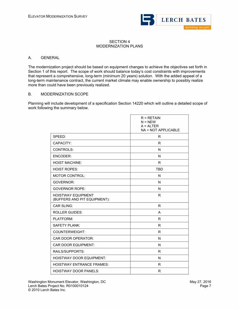
ELEVATOR MODERNIZATION SURVEY
Washington Monument Elevator, Washington, DC Lerch Bates Project No. R0100010124 © 2010 Lerch Bates Inc.
May 27, 2016 Page 7
SECTION 4 MODERNIZATION PLANS
A. GENERAL
The modernization project should be based on equipment changes to achieve the objectives set forth in Section 1 of this report. The scope of work should balance today’s cost constraints with improvements that represent a comprehensive, long-term (minimum 20 years) solution. With the added appeal of a long-term maintenance contract, the current market climate may enable ownership to possibly realize more than could have been previously realized.
B. MODERNIZATION SCOPE
Planning will include development of a specification Section 14220 which will outline a detailed scope of work following the summary below.
R = RETAIN N = NEW A = ALTER NA = NOT APPLICABLE
SPEED: R
CAPACITY: R
CONTROLS: N
ENCODER: N
HOIST MACHINE: R
HOIST ROPES: TBD
MOTOR CONTROL: N
GOVERNOR: N
GOVERNOR ROPE: N
HOISTWAY EQUIPMENT (BUFFERS AND PIT EQUIPMENT):
R
CAR SLING: R
ROLLER GUIDES: A
PLATFORM: R
SAFETY PLANK: R
COUNTERWEIGHT: R
CAR DOOR OPERATOR: N
CAR DOOR EQUIPMENT: N
RAILS/SUPPORTS: R
HOISTWAY DOOR EQUIPMENT: N
HOISTWAY ENTRANCE FRAMES: R
HOISTWAY DOOR PANELS: R

ELEVATOR MODERNIZATION SURVEY
Washington Monument Elevator, Washington, DC Lerch Bates Project No. R0100010124 © 2010 Lerch Bates Inc.
May 27, 2016 Page 8
R = RETAIN N = NEW A = ALTER NA = NOT APPLICABLE
HOISTWAY DOOR SILLS: R
HOISTWAY WIRING TRAVELING CABLES: N
SIGNALS :
CAR OPERATING PANELS: N
HALL PUSHBUTTONS: N
HALL LANTERNS: N
CAR POSITION INDICATORS: N
CAB INTERIOR FINISHES: BASE BID RETAIN, ALTERNATE BID FOR UPGRADES AND
HVAC
MACHINE ROOM: R & A
MACHINE ROOM LIGHTING: A
MACHINE ROOM OUTLETS: A
MACHINE ROOM ACCESS: N
MACHINE DISCONNECT SWITCH: N
PIT LIGHTING: N
PIT OUTLETS: A
As most new microprocessor based car and motor controls are “proprietary” in nature, the specifications should include the requirements to provide the necessary diagnostic service tools and technical manuals to provide maximum flexibility in contracting for future maintenance. As an alternative, non-proprietary controls could be specified, however, they will result in an increased initial installation cost of approximately 10%.
C. RECOMMENDATIONS
We recommend implementation of modernization scope outlined above to provide comprehensive modernization of the existing elevator. We recommend that Lerch Bates prepare our standard contracting package for ownership review. Final documents should include any scope and contractual modifications required by ownership.
In order to secure the most competitive prices, bid documents will include a Five Year Maintenance specification for pricing by all bidders.
We recommend inviting the four (4) major elevator companies, KONE, Otis Elevator, Schindler Elevator, and ThyssenKrupp. Consideration of award should be based upon the initial modernization investment as well as the five year cost of ownership.
Planning should include consideration of long lead times for fabrication of equipment and installation. Approximate time periods for the project are as follows.

ELEVATOR MODERNIZATION SURVEY
Washington Monument Elevator, Washington, DC Lerch Bates Project No. R0100010124 © 2010 Lerch Bates Inc.
May 27, 2016 Page 9
PREPARATION OF BID SPECIFICATION/OWNER REVIEWS 3 WEEKS
CONTRACT/BID REVIEW AND AWARD OF CONTRACT 3-4 WEEKS
SHOP DRAWING APPROVAL 6 WEEKS
EQUIPMENT FABRICATION 12 TO 20 WEEKS*
EQUIPMENT DELIVERY 2 WEEKS
INSTALLATION 18 WEEKS
FINAL ADJUSTING AND TESTING 2 WEEKS
TOTAL ELAPSED TIME FOR PROJECT 46 TO 55 WEEKS
Durations can vary by manufacturer. The bid documents will include solicitation of each contractor’s time frames. Installation could be completed on shift work to reduce time.
*Due to the custom nature of the control system, it could take up to 20 weeks to manufacture the control.

ELEVATOR MODERNIZATION SURVEY
Washington Monument Elevator, Washington, DC Lerch Bates Project No. R0100010124 © 2010 Lerch Bates Inc.
May 27, 2016 Page 10
APPENDIX A
SUPPORTING PHOTOGRAPHS

ELEVATOR MODERNIZATION SURVEY
Washington Monument Elevator, Washington, DC Lerch Bates Project No. R0100010124 © 2010 Lerch Bates Inc.
May 27, 2016 Page 11
1. Existing lobby entrance doors to be retained. 2. A new fire alarm panel should be provided.
3. Existing wall mounted hoistway access switch 4. Existing car station is to be replaced.

ELEVATOR MODERNIZATION SURVEY
Washington Monument Elevator, Washington, DC Lerch Bates Project No. R0100010124 © 2010 Lerch Bates Inc.
May 27, 2016 Page 12
5. Existing observation doors to be retained. 6. Existing machine room does not appear to be fire
rated.
7. Dover Governor should be replaced. 8. MCE controls need to be replaced.
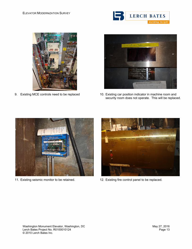
ELEVATOR MODERNIZATION SURVEY
Washington Monument Elevator, Washington, DC Lerch Bates Project No. R0100010124 © 2010 Lerch Bates Inc.
May 27, 2016 Page 13
9. Existing MCE controls need to be replaced 10. Existing car position indicator in machine room and security room does not operate. This will be replaced.
11. Existing seismic monitor to be retained. 12. Existing fire control panel to be replaced.

National Park Service U.S. Department of the Interior Repair and Upgrade Washington Monument Elevator National Mall and Memorial Parks, Washington, D.C.
Repair and Upgrade Washington Monument Elevator – Final September 2016 Appendix E – NPS Sustainability Checklist
Appendix E – NPS Sustainability Checklist

Fund Source: Gross Project Construction Cost:Predesign Begin Date:FY of Const. Funding
Park:State: Region:
Type of Building
Y, N, NA PointsConcisely explain how
credit/requirement is met at this milestone:
Y, N, NA PointsConcisely explain how
credit/requirement is met at this milestone:
Y, N, NA PointsConcisely explain how
credit/requirement is met at this milestone:
Y, N, NA PointsConcisely explain how
credit/requirement is met at this milestone:
Y, N, NA PointsConcisely explain how
credit/requirement is met at this milestone:
Y, N, NA PointsConcisely explain how
credit/requirement is met at this milestone:
SS Prereq 1Construction Activity Pollution Prevention
Y N/A Interior work only.
SS Credit 1 Site Selection Y 1
Site is not in flood plain, not prime farmland, no nearby wetlands, no endangered species, land is in public parkland
SS Credit 2 Development Density & Community Connectivity Y 2
Site is in a previously within 1/2 mi of basic services and has pedestrian access between buildings and services
SS Credit 3 Brownfield Redevelopment N 0
SS Credit 4.1 Alternative Transportation, Public Transportation Access Y 2
Project located within walking distance of public transportation and within 1/4 mile walking distance of 1 or more public or private bus lines
SS Credit 4.2Alternative Transportation, Bicycle Storage & Changing Rooms
N 0 No bike storage will be provided
SS Credit 4.3Alternative Transportation, Low-Emitting & Fuel-Efficient Vehicles
N 0 No parking or fueling stations will be provided
SS Credit 4.4 Alternative Transportation, Parking Capacity Y 1 Provide no new parking
NPS Project Sustainability Checklist Building and Non-Building Projects
(For New Construction or Renovation) LEED 2009 Edition
Project Title: Repair and Upgrade the Washington Monument Elevator Other $682,000
Not Certified/Missing Prereq.
Total LEED-NC Credits
Building Size (Square Feet)
0%
Architect/Engineer Firm:National CapitalDate: July 5, 2016 DC
LEED Certification Level Not Certified/Missing Prereq. Not Certified/Missing Prereq. Not Certified/Missing Prereq.
Construction
0%% Federal Regulations Achieved
Sustainable Sites (SS)Maximum LEED NC 2009 Credits: 26
Construction Documents
Missed Prereq.
CH2M Hill NAMA
Missed Prereq.
Not Certified/Missing Prereq.
Gross Building Construction Cost:
Missed Prereq. Missed Prereq. Missed Prereq.
Sustainability FeaturesPMIS Submission Predesign Schematic Design Design Development
Missed Prereq.
Gross Non Building (i.e. Site) Cost:
0% 0%
If Renovation, Exist. Bldg. CRV $0
Description:Park/PMIS: NAMA 224923 2017
Not Certified/Missing Prereq.
Repair, upgrade and modernize the Washington Monument Elevator 2016
0% 1300%
Project Type No Building
Form E 62 (5/26/10) 1

Y, N, NA PointsConcisely explain how
credit/requirement is met at this milestone:
Y, N, NA PointsConcisely explain how
credit/requirement is met at this milestone:
Y, N, NA PointsConcisely explain how
credit/requirement is met at this milestone:
Y, N, NA PointsConcisely explain how
credit/requirement is met at this milestone:
Y, N, NA PointsConcisely explain how
credit/requirement is met at this milestone:
Y, N, NA PointsConcisely explain how
credit/requirement is met at this milestone:
Construction Construction DocumentsSustainability Features
PMIS Submission Predesign Schematic Design Design Development
SS Credit 5.1 Site Development, Protect or Restore Habitat Y 1
Construction activity will minmize disturbance to existing site
SS Credit 5.2 Site Development, Maximize Open Space N 0 No new construction will be
conducted.
SS Credit 6.1Stormwater Design, Quantity Control (See EISA Section 438)
N 0 No new construction will be conducted.
SS Credit 6.2Stormwater Design, Quality Control (See EISA Section 438)
N 0
EISA 2007, Section 438 Protect Hydrology N N/A
No strategies to protect hydrology may be incorporated.
SS Credit 7.1 Heat Island Effect, Non-Roof N 0 No heat island effects, non-roof, are to be incorporated.
SS Credit 7.2 Heat Island Effect, Roof N 0 No heat island effects, roof, are to be incorporated.
SS Credit 8 Light Pollution Reduction Y 1
Interior light fixture replacements will produce no direct light spillage thorugh windows.
2006 NPS Mgmt Policies (Para.
4.9)Soundscape Preservation Y N/A No exterior noise producing
equipment.
2006 NPS Mgmt Policies (Para.
4.10)Dark Sky Preservation NA N/A Dark sky preservation is not
applicable to this project.
Missed Prereq. 8 Missed
Prereq.Missed Prereq.
Missed Prereq.
Missed Prereq.LEED-NC Subtotal
Form E 62 (5/26/10) 2

Y, N, NA PointsConcisely explain how
credit/requirement is met at this milestone:
Y, N, NA PointsConcisely explain how
credit/requirement is met at this milestone:
Y, N, NA PointsConcisely explain how
credit/requirement is met at this milestone:
Y, N, NA PointsConcisely explain how
credit/requirement is met at this milestone:
Y, N, NA PointsConcisely explain how
credit/requirement is met at this milestone:
Y, N, NA PointsConcisely explain how
credit/requirement is met at this milestone:
Construction Construction DocumentsSustainability Features
PMIS Submission Predesign Schematic Design Design Development
Y, N, N/A PointsConcisely explain how
credit/requirement is met at this milestone:
Y, N, N/A PointsConcisely explain how
credit/requirement is met at this milestone:
Y, N, N/A PointsConcisely explain how
credit/requirement is met at this milestone:
Y, N, N/A PointsConcisely explain how
credit/requirement is met at this milestone:
Y, N, N/A PointsConcisely explain how
credit/requirement is met at this milestone:
Y, N, N/A PointsConcisely explain how
credit/requirement is met at this milestone:
WE Prereq 1Water Use Reduction, 20% Reduction (see Guiding Principle III ‐Protect and Conserve Water)
NA N/A No water use reduction measures included in project.
WE Credit 1
Water Efficient Landscaping, Reduce by 50% (see Guiding Principle III ‐ Protect and Conserve Water)
NA 0
The project will not affect the landscape of the Monument Grounds nor will it require irrigation.
WE Credit 1(cont'd)
Water Efficient Landscaping, No Potable Use or No Irrigation
N 0
WE Credit 2 Innovative Wastewater Technologies N 0
NPS Policy Water Metering NA N/A
EPACT 2005, Section 109
Water Used for Energy Conservation NA N/A
WE Credit 3 Water Use Reduction (30%, 35%, 40%) N 0
Missed Prereq.
Missed Prereq. 0 Missed
Prereq.Missed Prereq.
Missed Prereq.
Y, N, N/A PointsConcisely explain how
credit/requirement is met at this milestone:
Y, N, N/A PointsConcisely explain how
credit/requirement is met at this milestone:
Y, N, N/A PointsConcisely explain how
credit/requirement is met at this milestone:
Y, N, N/A PointsConcisely explain how
credit/requirement is met at this milestone:
Y, N, N/A PointsConcisely explain how
credit/requirement is met at this milestone:
Y, N, N/A PointsConcisely explain how
credit/requirement is met at this milestone:
EA Prereq 1
Fundamental Commissioning of the Building Energy Systems * (see Guiding Principle I ‐ Employ Integrated Design Principles)
Y N/A
Fundamental Commisioning will be performed . Commisioning Plan will be developed during subsequant phases.
Construction
Water Efficiency (WE)Maximum LEED NC 2009 Credits: 10
Sustainability FeaturesPMIS Submission Predesign Schematic Design Design Development Construction Documents Construction
LEED-NC Subtotal
Energy & Atmosphere (EA)Maximum LEED NC 2009 Credits: 35
Sustainability FeaturesPMIS Submission Predesign Schematic Design Design Development Construction Documents
Form E 62 (5/26/10) 3

Y, N, NA PointsConcisely explain how
credit/requirement is met at this milestone:
Y, N, NA PointsConcisely explain how
credit/requirement is met at this milestone:
Y, N, NA PointsConcisely explain how
credit/requirement is met at this milestone:
Y, N, NA PointsConcisely explain how
credit/requirement is met at this milestone:
Y, N, NA PointsConcisely explain how
credit/requirement is met at this milestone:
Y, N, NA PointsConcisely explain how
credit/requirement is met at this milestone:
Construction Construction DocumentsSustainability Features
PMIS Submission Predesign Schematic Design Design Development
EA Prereq 2Minimum Energy Performance (see Guiding Principle II Optimize Energy Performance)
NA N/A
EA Prereq 3
Fundamental Refrigerant Management (see Guiding Principle V ‐ Reduce Environmental Impact of Materials)
Y N/AZero use of CFC based refrigerants in HVAC and refrigerant systems.
EA Credit 1
Optimize Energy Performance:** (Federal Regulations require 30% for New Construction and 20% for Existing Building Renovation. Note that this automatically equates to 10 Points for New Construction and 7 Points for Existing Building Renovation.) (see Guiding Principle II ‐ Optimize Energy Performance)
NA 0
EISA 2007, Section 433
Reduce Fossil Fuel Derived Energy NA N/A
No new construction or renovation exceeding $2.5 million.
EO 13423, Sec. 2.(h)
Energy Efficient Electronic Products (Select EPEAT) (Predominantly relates to purchases of desktop/laptop computers and peripherals)
Y N/AEnergy Efficient Electronic products are anticpated to be used by NPS
CFR Title 10, Part 436.4
Procure Energy Star or FEMP designated products
Y N/AEnergy Star lighting and HVAC equipment is anticipated to be incorproated
EPACT 2005, Section 104
Premium Efficiency Electric Motors NA N/A
EISA 2007, Section 523
On-Site Renewable Energy*** Solar Thermal for Hot Water (Choose NA if proven not life cycle cost effective)
N N/A No availability for installation.
EA Credit 2 On-Site Renewable Energy*** 1%-13% Renewable Energy N 0 No on site renewable energy
systems are anticipated.
EA Credit 3
Enhanced Commissioning (required for projects with building size > 5,000 sf) (see Guiding Principle I ‐ Employ Integrated Design Principles)
NA 0 No enhanced commissioning is anticipated
EA Credit 4Enhanced Refrigerant Management (see Guiding Principle V ‐ Reduce Environmental Impact of Materials)
N 2
Refrigerant selection minimizes or eliminates ozone depletion and global climate change.
Form E 62 (5/26/10) 4

Y, N, NA PointsConcisely explain how
credit/requirement is met at this milestone:
Y, N, NA PointsConcisely explain how
credit/requirement is met at this milestone:
Y, N, NA PointsConcisely explain how
credit/requirement is met at this milestone:
Y, N, NA PointsConcisely explain how
credit/requirement is met at this milestone:
Y, N, NA PointsConcisely explain how
credit/requirement is met at this milestone:
Y, N, NA PointsConcisely explain how
credit/requirement is met at this milestone:
Construction Construction DocumentsSustainability Features
PMIS Submission Predesign Schematic Design Design Development
EA Credit 5Measurement & Verification (see Guiding Principle II ‐ Optimize Energy Performance)
NA 0 No M&V plan anticipated for project.
EA Credit 6 Green Power N 0
Missed Prereq.
Missed Prereq. 0 Missed
Prereq.Missed Prereq.
Missed Prereq.
Y, N, N/A PointsConcisely explain how
credit/requirement is met at this milestone:
Y, N, N/A PointsConcisely explain how
credit/requirement is met at this milestone:
Y, N, N/A PointsConcisely explain how
credit/requirement is met at this milestone:
Y, N, N/A PointsConcisely explain how
credit/requirement is met at this milestone:
Y, N, N/A PointsConcisely explain how
credit/requirement is met at this milestone:
Y, N, N/A PointsConcisely explain how
credit/requirement is met at this milestone:
MR Prereq 1 Storage & Collection of Recyclables N N/A
No recylcing bins are currently provided near the visitors facility. Accommodations are made at the Monument Lodge. This practice will continue to be in place for the proposed facility.
MR Credit 1.1 Building Reuse, Maintain Existing Walls, Floors & Roof N 0 No opportunities to reuse
materials are available
MR Credit 1.2Building Reuse, Maintain Interior Nonstructural Elements
N 0 No opportunities to reuse materials are available
MR Credit 2
Construction Waste Management, Divert 50% from Disposal (see Guiding Principle V ‐ Reduce Environmental Impact of Materials)
NA 0 No waste management plan anticipated.
MR Credit 2(cont'd)
Construction Waste Management, Divert 75% from Disposal
N 0 No waste management anticipated.
MR Credit 3 Materials Reuse N 0 No opportunities to reuse materials are available
MR Credit 4
Recycled Content, 10% (post‐consumer + ½ pre‐consumer). Use EPA's CPG for designated products to use)
N 0 No opportunities to reuse materials are available
MR Credit 4 Recycled Content, 20% (post-consumer + ½ pre-consumer) N 0 No opportunities to reuse
materials are available
MR Credit 5Regional Materials, Extracted, Processed & Manufactured Regionally
N 0
It is uncertain if all regionally manufactured materials will be used but it is anticpated that some will be used.
LEED-NC Subtotal
Materials & Resources (MR)Maximum LEED NC 2009 Credits: 14
Sustainability FeaturesPMIS Submission Construction Predesign Schematic Design Design Development Construction Documents
Form E 62 (5/26/10) 5

Y, N, NA PointsConcisely explain how
credit/requirement is met at this milestone:
Y, N, NA PointsConcisely explain how
credit/requirement is met at this milestone:
Y, N, NA PointsConcisely explain how
credit/requirement is met at this milestone:
Y, N, NA PointsConcisely explain how
credit/requirement is met at this milestone:
Y, N, NA PointsConcisely explain how
credit/requirement is met at this milestone:
Y, N, NA PointsConcisely explain how
credit/requirement is met at this milestone:
Construction Construction DocumentsSustainability Features
PMIS Submission Predesign Schematic Design Design Development
EO 13423, Sec. 2.(d)
Biopreferred Products N N/A
MR Credit 6 Rapidly Renewable Materials N 0It is not anticipated that rapidly renewable materials will be used
MR Credit 7Certified Wood (see Guiding Principle V ‐ Reduce Environmental Impact of Materials)
NA 0
No certified wood is anticipated to be used for permanent installation. Some may be used during construction.
Missed Prereq.
Missed Prereq. 0 Missed
Prereq.Missed Prereq.
Missed Prereq.
Y, N, N/A PointsConcisely explain how
credit/requirement is met at this milestone:
Y, N, N/A PointsConcisely explain how
credit/requirement is met at this milestone:
Y, N, N/A PointsConcisely explain how
credit/requirement is met at this milestone:
Y, N, N/A PointsConcisely explain how
credit/requirement is met at this milestone:
Y, N, N/A PointsConcisely explain how
credit/requirement is met at this milestone:
Y, N, N/A PointsConcisely explain how
credit/requirement is met at this milestone:
EQ Prereq 1Minimum IAQ Performance (See Guiding Principle IV, Enhance Indoor Environmental Quality)
Y N/A
Only anticipated to replace a small DX mechanical system but the goal is to meet the requirements of ASHRAE 62.1
EQ Prereq 2 Environmental Tobacco Smoke (ETS) Control Y N/A
Eating, drinking (with the exception of water), and smoking are prohibited in the Washington Monument, inside and around the plaza within the flagpoles.
EQ Credit 1 Outdoor Air Delivery Monitoring Y 1 Outdoor air delivery monitoring
could be used.
EQ Credit 2 Increased Ventilation N 0 No increased ventilation proposed for this project.
EQ Credit 3.1
Construction IAQ Management Plan, During Construction (See Guiding Principle IV, Enhance Indoor Environmental Quality)
Y 1 An IAQ will be prepared in Design Development
EQ Credit 3.2
Construction IAQ Management Plan, Before Occupancy (See Guiding Principle IV, Enhance Indoor Environmental Quality)
Y 1 An IAQ will be prepared in Design Development
EQ Credit 4.1
Low‐Emitting Materials, Adhesives & Sealants (See Guiding Principle IV, Enhance Indoor Environmental Quality)
Y 1 Low VOC materials are anticipated to be used.
EQ Credit 4.2
Low‐Emitting Materials, Paints & Coatings (See Guiding Principle IV, Enhance Indoor Environmental Quality)
Y 1 Low VOC materials are anticipated to be used.
PMIS Submission Predesign
LEED-NC Subtotal
Indoor Environmental Quality (EQ)Maximum LEED NC 2009 Credits: 15
Schematic Design Design Development Construction Documents Construction Sustainability Features
Form E 62 (5/26/10) 6

Y, N, NA PointsConcisely explain how
credit/requirement is met at this milestone:
Y, N, NA PointsConcisely explain how
credit/requirement is met at this milestone:
Y, N, NA PointsConcisely explain how
credit/requirement is met at this milestone:
Y, N, NA PointsConcisely explain how
credit/requirement is met at this milestone:
Y, N, NA PointsConcisely explain how
credit/requirement is met at this milestone:
Y, N, NA PointsConcisely explain how
credit/requirement is met at this milestone:
Construction Construction DocumentsSustainability Features
PMIS Submission Predesign Schematic Design Design Development
EQ Credit 4.3
Low‐Emitting Materials, Flooring Materials (See Guiding Principle IV, Enhance Indoor Environmental Quality)
NA 0No low emitting flooring systems are anticipated to be used.
EQ Credit 4.4Low-Emitting Materials, Composite Wood & Agrifiber Products
N 0No low emitting composite wood materials are anticipated to be used.
EQ Credit 5 Indoor Chemical & Pollutant Source Control N 0
MOU Guiding Principles & EO
13423Moisture Control NA N/A No moisture control needs
anticipated for the project.
EQ Credit 6.1Controllability of Systems, Lighting (See Guiding Principle IV, Enhance Indoor Environmental Quality)
N 0 No lighting controls upgrades are anticipated for this project.
EQ Credit 6.2 Controllability of Systems, Thermal Comfort N 0 Individual thermal control is
not anticipated.
EQ Credit 7.1Thermal Comfort, Design (See Guiding Principle IV, Enhance Indoor Environmental Quality)
Y 1
Thermal comfort design is anticipated to meet requirements of ASHRAE 55-2004
EQ Credit 7.2 Thermal Comfort, Verification N 0Thermal comfort verification is not anticipated as part of the project.
EQ Credit 8.1
Daylight & Views, Daylight 75% of Spaces (See Guiding Principle IV, Enhance Indoor Environmental Quality)
NA 0 Daylighting is not anticipated as part of this project.
EQ Credit 8.2 Daylight & Views, Views for 90% of Spaces N 0
Missed Prereq. 6 0 Missed
Prereq.Missed Prereq.
Missed Prereq.
Y, N, N/A PointsConcisely explain how
credit/requirement is met at this milestone:
Y, N, N/A PointsConcisely explain how
credit/requirement is met at this milestone:
Y, N, N/A PointsConcisely explain how
credit/requirement is met at this milestone:
Y, N, N/A PointsConcisely explain how
credit/requirement is met at this milestone:
Y, N, N/A PointsConcisely explain how
credit/requirement is met at this milestone:
Y, N, N/A PointsConcisely explain how
credit/requirement is met at this milestone:
ID Credit 1.1 Innovation in Design: Provide Specific Title TBD
ID Credit 1.2 Innovation in Design: Provide Specific Title TBD
ID Credit 1.3 Innovation in Design: Provide Specific Title TBD
ID Credit 1.4 Innovation in Design: Provide Specific Title TBD
Design Development Construction DocumentsSchematic DesignPMIS Submission Predesign
Innovation & Design Process (ID)Maximum LEED NC 2009 Credits: 6
Sustainability FeaturesConstruction
LEED-NC Subtotal
1
Form E 62 (5/26/10) 7

Y, N, NA PointsConcisely explain how
credit/requirement is met at this milestone:
Y, N, NA PointsConcisely explain how
credit/requirement is met at this milestone:
Y, N, NA PointsConcisely explain how
credit/requirement is met at this milestone:
Y, N, NA PointsConcisely explain how
credit/requirement is met at this milestone:
Y, N, NA PointsConcisely explain how
credit/requirement is met at this milestone:
Y, N, NA PointsConcisely explain how
credit/requirement is met at this milestone:
Construction Construction DocumentsSustainability Features
PMIS Submission Predesign Schematic Design Design Development
ID Credit 1.5 Innovation in Design: Provide Specific Title TBD
ID Credit 2 LEED® Accredited Professional
Y LEED AP will be included in Design Development process
0 1 0 0 0 0
Y, N, N/A PointsConcisely explain how
credit/requirement is met at this milestone:
Y, N, N/A PointsConcisely explain how
credit/requirement is met at this milestone:
Y, N, N/A PointsConcisely explain how
credit/requirement is met at this milestone:
Y, N, N/A PointsConcisely explain how
credit/requirement is met at this milestone:
Y, N, N/A PointsConcisely explain how
credit/requirement is met at this milestone:
Y, N, N/A PointsConcisely explain how
credit/requirement is met at this milestone:
RP Credit 1.1 Regional Priority Credit: Region Defined 0 TBD
RP Credit 1.2 Regional Priority Credit: Region Defined 0 TBD
RP Credit 1.3 Regional Priority Credit: Region Defined 0 TBD
RP Credit 1.4 Regional Priority Credit: Region Defined 0 TBD
0 0 0 0 0 0
Y, N, N/A PointsConcisely explain how
credit/requirement is met at this milestone:
Y, N, N/A PointsConcisely explain how
credit/requirement is met at this milestone:
Y, N, N/A PointsConcisely explain how
credit/requirement is met at this milestone:
Y, N, N/A PointsConcisely explain how
credit/requirement is met at this milestone:
Y, N, N/A PointsConcisely explain how
credit/requirement is met at this milestone:
Y, N, N/A PointsConcisely explain how
credit/requirement is met at this milestone:
MOU Guiding Principles & EO 13423 (pg. 3)
Complete Integrated Design Narrative During Predesign Only
N N/A N/A N/A N/A N/A N/A N/A N/A N/A N/A N/A N/A N/A
LEED Certification Rating SystemCertified: 40-49 points, Silver: 50-59 points, Gold: 60-79 points, Platinum: 80+ points
For more information on LEED Certification and credits, visit www.usgbc.org
LEED-NC Subtotal
Sustainability FeaturesPMIS Submission Predesign Schematic Design Design Development Construction Documents
Construction Documents Construction
LEED-NC Subtotal
Construction
Non-LEED-NC Federal RequirementsMaximum LEED NC 2009 Credits: 26
Predesign
** For new building projects of 5,000 GSF or more, perform whole building energy simulation(s) in accordance with ASHRAE 90.1, 2007 (or IECC 2006 for residential) to show performance at least 30% better (20% for major renovations) than a code compliant similar building. If it can be shown that meeting the 30% performance standard for new construction (or 20% for major renovations) is not life cycle cost effective (over 40 years ‐ not 25 years per a recent regulatory change) then the project must incorporate the maximum energy savings that can be shown to be life cycle cost effective. For new building projects with a lower net construction value, an alternative method is to meet or exceed the minimum requirements prescribed by the ASHRAE Advanced Energy Design Guide (a much simpler prescriptive method for achieving the target) appropriate for the project's building. For buildings without an appropriate Advanced Energy Design Guide perform whole building energy simulation(s) in accordance with ASHRAE 90.1, 2007 (or IECC 2006 for residential).
Schematic Design
Regional Priority (RP)Maximum LEED NC 2009 Credits: 4
Design Development
Fulfillment of Guiding Principles for HPSB completes 18 LEED NC credits and 6 prerequisites.
*** The federal requirement (from EISA 2007) that relates to these LEED‐NC credits is "Where life cycle cost effective, design systems to provide not less than 30 percent of the hot water demand through the installation and use of solar hot water heaters." The LEED credits for this item stipulates a percentage of total energy consumption to be provided by on site renewable sources. In some cases meeting the federal requirement will also meet the LEED requirement for these credits.
Sustainability FeaturesPMIS Submission
* For new buildings of 5,000 GSF or more and major renovations to buildings greter than or equal to 5,000 GSF, contract with an independent Commissioning Authority and comply with ASHRAE 0‐2005, "The Commissioning Process". For smaller projects, comply with the requirements of LEED NC 2009, EA Prerequisite 1, "Fundamental Commissioning of the Building Energy Systems" (which allows the commissioning authority to be an employee of the design firm).
Form E 62 (5/26/10) 8