Embed Size (px)
Citation preview

POSIVA OY
POSIVA 99·18
Design report of the disposal canister
for twelve fuel assemblies
Heikki Raiko
VTT Energy
Jukka-Pekka Salo Posiva Oy
May 1999
Mikonkatu 15 A. FIN-001 00 HELSINKI, FINLAND
Phone (09) 2280 30 (nat.). (+358-9-) 2280 30 (int.)
l=<>v /nQ\ ??Rn ':!71Q fnAt \ f+~FiR-Q-\ ??RO ~71~ lint.)

-tTT- ENERGY Research organisation and address
VTT Energy, Nuclear energy P.O. Box 1604 FIN-02044 VTT, FINLAND
Project manager
Heikki Raiko
Diary code
ENE4-53T -98
Project title and reference code
Encapsulation technology (N6SU00017, 45KAPSELI)
Report title and author(s)
Customer
POSIVAOY Mikonkatu 15 A FIN-00 1 00, Helsinki, FINLAND
Contact person
Jukka-Pekka Salo :i '/, Y. I 1VJj {!;; 1,~ • 7 ~· ';> '"" . ... "'\1' . Order reference
'-1.. ~ . \ ~~")·~ ~~);J.. -Report identification & Pages Date V, J ;-..cz c( t, ENE4/18/99 26.4.1999
9789/98/JPS, 1.12.1998
64 p. (This revised version substitutes the 6.4.1999 version)
DESIGN REPORT OF THE DISPOSAL CANISTER FOR TWELVE FUEL ASSEMBLIES
Heikki Raiko
Summary
The design of the canister for nuclear fuel disposal is presented in this report. The canister structure consists of a massive nodular graphite cast iron insert with emplacement holes for twelve fuel assemblies and a 50 mm thick overpack of copper. The structural details are given, the manufacturing processes are discussed and assessed, the handling, seal welding and transport to the deposition hole in the repository is described. All manufacturing and handling methods are based on technologies available today.
The mechanical dimensioning calculations of the canister design with two variations (for BWR and for VVER 440 fuel) are documented in this report. The mechanical strength of the design is excellent. The collapse external pressure load is about 100 MP a.
The subcriticality analysis of the canister shows that the required safety criteria are met even in case where the fuel assemblies are fresh and the void of the canister is filled with water.
The radiation dose level analysis shows that the design requirements are met with a good margin. The maximum of the average gamma dose rate on the canister surface is less than 150 mSvlh and the local maximum is less than 250 mSvlh. Neutron dose rates outside the canisters are much lower than gamma dose rates. The maximum average value of neutron dose is 10- 15 mSv/h.
The thermal analysis of the canister and the surrounding rock in repository gives the minimum grid distances of the canisters in the repository configuration. The span between canisters in the disposal tunnels shall be 7.5 - 8.0 metres. Site specific thermal properties of the rock are used in the analyses. The limiting thermal criteria is that the temperature of the bentonite buffer outside the canister shall not exceed + 100 °C.
Reviewed by Principal author or Project manager
~«< (JZCA-v-Ct-Product manager, Heikki Raiko
I - ./;.1,~; i· ~·'··'-:"~,
.{;;up'M~~g~r, Seppo Vuori
Availability statement
To be published as the Posiva Report 99-18 Lasse Mattila Research Manager, Nuclear Energy
The use of the name of the Technical Research Centre of Finland (VTT) in advertising or publication in part of this report is only permissible by written authorisation from the Technical Research Centre of Finland

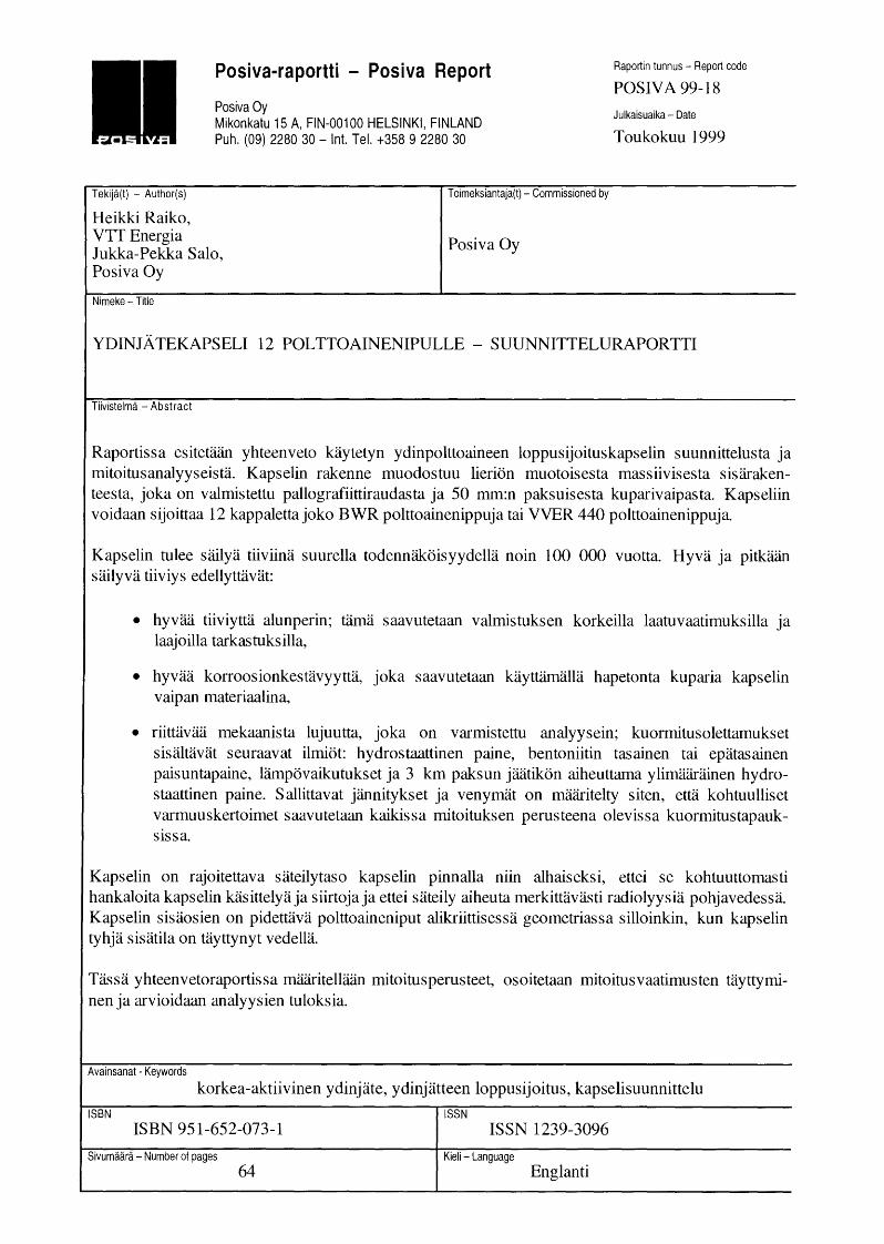
Posiva-raportti - Posiva Report
Posiva Oy Mikonkatu 15 A, FIN-001 00 HELSINKI, FINLAND Puh. (09) 2280 30- lnt. Tel. +358 9 2280 30
Tekija(t) - Author(s)
Heikki Raiko, VTIEnergy Jukka-Pekka Salo, Posiva Oy
Nimeke- Title
Toimeksiantaja(t)- Commissioned by
Posiva Oy
Raportin tunnus - Report code
POSIVA 99-18
Julkaisuaika- Date
May 1999
DESIGN REPORT OF THE DISPOSAL CANISTER FOR TWELVE FUEL ASSEMBLIES
Tiivistelma - Abstract
The report provides a summary of the design of the canister for final disposal of spent nuclear fuel. The canister structure consists of a cylindrical massive nodular graphite cast iron insert covered by a 50 mm thick copper overlay. The capacity of the canister is 12 assemblies of BWR or VVER 440 fuel.
The canister shall be tight with a high probability for about 100 000 years. The good and long lasting tightness requires:
• good initial tightness that is achieved by high quality requirements and extensive quality control,
• good corrosion resistance, which is obtained by the overpack of oxygen free copper and
• mechanical strength of the canister, that is ensured by analyses; the following loads are considered: hydrostatic pressure, even and uneven swelling pressure of bentonite, thermal effects, and elevated hydrostatic pressure during glaciation. The allowed stresses and strains are set in such a way that reasonable engineering safety factors are obtained in all assessed design base loading cases.
The canister shall limit the radiation dose rate outside the canister to minimise the radiolysis of the water in the vicinity of the canister. The canister insert shall keep the fuel assemblies in a subcritical configuration even if the void in the canister is filled with water due to postulated leakage.
The design basis of the canister is set, the performed analyses are summarised and the results are assessed and discussed in the report.
Avainsanat- Keywords
high active nuclear waste, nuclear fuel disposal, canister design
ISBN ISSN ISBN 951-652-073-1 ISSN 1239-3096
Sivumaara- Number of pages Kieli - Language 64 English
Posiva-raportti - Posiva Report
Posiva Oy Mikonkatu 15 A, FIN-001 00 HELSINKI, FINLAND Puh. (09) 2280 30- lnt. Tel. +358 9 2280 30
Raportin tunnus - Report code
POSIV A 99-18
Julkaisuaika- Date
Toukokuu 1999
Tekija(t) - Author(s)
Heikki Raiko, VTI Energia Jukka-Pekka Salo, Posiva Oy
Toimeksiantaja(t)- Commissioned by
Posiva Oy
Nimeke- Title
YDINJATEKAPSELI 12 POLTTOAINENIPULLE- SUUNNITTELURAPORTTI
Tiivistelma -Abstract
Raportissa esitetaan yhteenveto kaytetyn ydinpolttoaineen loppusijoituskapselin suunnittelusta ja mitoitusanalyyseista. Kapselin rakenne muodostuu lierion muotoisesta massiivisesta sisarakenteesta, joka on valmistettu pallografiittiraudasta ja 50 mm:n paksuisesta kuparivaipasta. Kapseliin voidaan sijoittaa 12 kappalettajoko BWR polttoainenippuja tai VVER 440 polttoainenippuja.
Kapselin tulee sailya tiiviina suurella todennakoisyydella noin 100 000 vuotta. Hyva ja pitkaan sailyva tiiviys edellyttavat:
• hyvaa tiiviytta alunperin; tama saavutetaan valmistuksen korkeilla laatuvaatimuksilla ja laa j o ill a tarkas tuks ill a,
• hyvaa korroosionkestavyytta, joka saavutetaan kayttamalla hapetonta kuparia kapselin vaipan materiaalina,
• riittavaa mekaanista lujuutta, joka on varmistettu analyysein; kuormitusolettamukset sisaltavat seuraavat ilmiot: hydrostaattinen paine, bentoniitin tasainen tai epatasainen paisuntapaine, lampovaikutukset ja 3 km paksun jaatikon aiheuttama ylimaarainen hydrostaattinen pain e. S allittavat jannitykset ja venymat on maaritelty si ten, etta kohtuulliset varmuuskertoimet saavutetaan kaikissa mitoituksen perusteena olevissa kuormitustapauksissa.
Kapselin on rajoitettava sateilytaso kapselin pinnalla nun alhaiseksi, ettei se kohtuuttomasti hankaloita kapselin kasittelya ja siirtoja ja ettei sateily aiheuta merkittavasti radiolyysia pohjavedessa. Kapselin sisaosien on pidettava polttoaineniput alikriittisessa geometriassa silloinkin, kun kapselin tyhja sisatila on tayttynyt vedella.
Tassa yhteenvetoraportissa maaritellaan mitoitusperusteet, osoitetaan mitoitusvaatimusten tayttyminen ja arvioidaan analyysien tuloksia.
Avainsanat- Keywords
korkea-aktiivinen ydinjate, ydinjatteen loppusijoitus, kapselisuunnittelu
ISBN ISSN ISBN 951-652-073-1 ISSN 1239-3096
Sivumaara- Number of pages Kieli - Language 64 Englanti

1
TABLE OF CONTENTS
page Abstract
Tiivistelma
1 INTRODUCTION ........................................................................................................ 5
2 BASIC REQUIREMENTS ........................................................................................... 7 2.1 Spent fuel characteristics ..................................................................................... 8 2.2 Radiation shielding .............................................................................................. 9 2.3 Corrosion resistance, life time and leak tightness .............................................. 9 2.4 Dimensional constraints .................................................................................... 1 0 2.5 Manufacturing tolerances .................................................................................. 1 0 2. 6 Heat loads and allowable temperatures ............................................................ 11 2. 7 Mechanical design load .................................................................................... 11 2.8 Allowable stresses and strains and required safety factors ............................... 14 2.9 Safety classification ........................................................................................... 15
3 MATERIAL SELECTION AND SPECIFICATION OF PROPERTIES ................. 17 3.1 Specification of manufacturing materials ......................................................... 1 7 3.2 Quality controls for the materials manufacture ................................................ 19
4 CANISTER DESCRIPTION ...................................................................................... 21 4.1 General description and dimensions of the canister ......................................... 21 4.2 Insert variations for BWR and VVER 440 fuel ................................................ 23 4.3 Encapsulation process ....................................................................................... 26 4.4 Canister handling operations ............................................................................. 26 4.5 Opening and unloading of the canister ............................................................. 27
5 MANUFACTURING PROCEDUR£ ........................................................................ 29 5.1 Pre-fabrication of the canister ........................................................................... 29 5.2 Installation tolerances ........................................................................................ 29 5.3 Quality controls for the pre-fabrication ............................................................ 30 5.4 Sealing weld of the canister lid ......................................................................... 30 5.5 Sealing weld quality control.. ............................................................................ 32 5.6 Repair procedures .............................................................................................. 34
6 MECHANICAL AND THERMAL-MECHANICAL DIMENSIONING ................ 35 6.1 Strength analysis of the insert ........................................................................... 35 6.2 Flat cover dimensioning .................................................................................... 41 6.3 Screws and gasket of the flat ends ................................................................... .42 6.4 Copper overpack and the lifting shoulder ......................................................... 42 6.5 Operation temperature ....................................................................................... 45

2
6.6 Cooling properties of the canister .................................................................... .47 6.7 Thermal stresses and deformations ................................................................... 47 6.8 Creep strains caused by shrinking in cooling period ....................................... .47
7 RADIATION SHIELDING ........................................................................................ 49
8 CRITICALITY SAFETY ........................................................................................... 51
9 SUMMARY ................................................................................................................ 53
REFERENCES ............................................................... , ..................................................... 55
APPENDIX A: FEM-results from the collapse load analysis of the canister insert ........... 59

3
FOREWORD
The report is prepared by VTT Energy for Posiva Oy on contract. The project manager in Posiva has been Jukka-Pekka Salo. Special thanks are addressed to doctors Lars Werme of SKB Ab and Timo Vieno of VTT Energy, who have patiently discussed and commented on the critical topics of the design, and colleagues from VTT Energy, Kari Ikonen and Markku Anttila, who have prepared and documented the analyses of strength, criticality safety and radiation shielding of the canister.

4

5
1 INTRODUCTION
The report constitutes a summary of the research and development work made for the design and dimensioning of the canister for nuclear fuel disposal. The basic requirements for dimensioning are set, the design is introduced, and the manufacturing processes and technology are described and assessed in the report. The mechanical strength of the canister in various loading conditions is analysed. In addition, the corrosion, thermal, radiation shielding and criticality analyses of the canister are summarised and discussed.
The canister construction type introduced here is a copper canister with a cast insert, which is designed for nuclear fuel disposal in a deep repository in the crystalline bedrock. Two canister types are dimensioned: one for BWR fuel and another for VVER 440 type PWR fuel.
The copper canister with a cast insert consists of two major components: the massive nodular graphite cast iron insert and the corrosion resistant overpack of oxygen free copper. The insert provides mechanical strength and radiation shielding, and keeps the fuel assemblies in a fixed configuration. During the final welding of the lid of the copper overpack, the insert acts as a gas tight vessel keeping the fuel assemblies with the possible inert gas atmosphere in the void space isolated from the EB-welding process made in vacuum. During the transfer and handling operations the canister is gripped from the shoulder at the top lid corner with a mechanical gripping device.
The canisters presented here contain 12 positions for fuel assemblies. The amount of uranium in each canister ranges from 1.44 to 2.16 tons depending on the fuel type. The total weight of the canister including the 12 fuel assemblies is 18.7 to 24.5 tons, respectively. The outside diameter of the canister for both types is 1.052 m and the total length is either 3.6 or 4.8 m.

6

7
2 BASIC REQUIREMENTS
The basic design requirements of the canister for nuclear waste disposal are as follows:
• The canister must not be penetrated by corrosion during the first 100 000 years after disposal.
• The fuel to be disposed of has an average bumup of 35- 36 MWd/kgU, the estimated maximum bumup per fuel assembly is 50 MW d/kgU, the minimum cooling time of the assemblies is 20 years.
• The maximum dose rate on the outer surface of the canister shall be less than 1 Gy/h to minimise the radiolysis of water or altering the bentonite buffer outside the canister.
• The canisters shall be subcritical even if the void inside the canister is filled with water. The subcriticality is to be checked for a single canister and a set of canisters in the buffer storage of the encapsulation plant and in the disposal holes of the repository.
• The canister surface temperature in repository condition shall not exceed + 100 °C to guarantee the chemical stability of the surrounding bentonite.
• The canister shall be designed to withstand the loads caused by disposal at a depth of 400 to 700 m, which entails an evenly distributed load of 7 MP a hydrostatic pressure from ground water and 7 MP a pressure from swelling of bentonite.
• The canister strength shall be demonstrated also in non-symmetric cases of bentonite swelling without groundwater pressure and in a case of additional hydrostatic load caused by 3 kilometres of ice during a glaciation.
• The strength of the copper overpack is to be checked for handling and operational loads during the disposal process.
• The manufacturing tolerance of the gap between the copper overpack and the iron insert has to be limited in such a way that the plastic or creep strain in copper will be less than 5% in case the copper overpack is deformed against the insert.

8
2.1 Spent fuel characteristics
The spent fuel characteristics for both ABB Atom BWR reactor and VVER 440 reactor are given in Table 1. The length of fuel rods and assemblies grows in the reactor some 10 to 25 mm depending on the bumup.
TABLE 1. Fuel characteristics for BWR and VVER 440 fuel. VVER 440 fuel assembly with integral fuel channel, BWRfuel assembly with separable channel.
FUEL TYPE ABBAtomBWR VVER440PWR Assembly configuration square hexagonal Total length (m) 4.1275 3.195 Fuel rod length (m) 4.008 2.572 Sectional dimension (mm) 132 * 144 Number of rods per assembly 63- 100 126 Mass of uranium (kg) 172- 180 120 Assembly mass without channel_(kg) 256-257 180 Flow channel mass (kg) 40 30-34 Flow channel dimension(mm) 139 (square) 144 (hexagonal) Nominal length with flow channel (m) 4.398 3.195 Maximum average bumup of a fuel 50 38 assembly (MW d/kgU) Average bum up of all the fuel 35 36 (MWdlkgU) Enrichment U-235 (%) 3.3- 3.8 3.6-4.0 Minimum cooling time (years) 20 20 Average cooling time (years) 28 27 Decay heat at average cooling time (W /tU) 832 880 Decay heat at 20 y, aver. (W/tU) 951 988 Decay heat at 200 y, aver. (W/tU) 176 190 Deca_yheat at 2000 y, aver. (W/tU) 29.1 32.7
*) The top end handle of the BWR fuel assembly has some more extensive details, max. dimension 151 mm.
The BWR fuel assemblies will be inserted with fuel channels into the canister. The canister is dimensioned for 8x8-, 9x9- and 1 Ox1 0-type fuel assemblies with the standard fuel channel.
The VVER 440 fuel assembly is an integral structure with the fuel channel. The channel makes the assembly much longer than the fuel pin.
The maximum average bumup of a fuel assembly is assumed to be 50 MWd/kgU. Modem BWR fuel assemblies have the so-called axial reflectors made of natural uranium at their
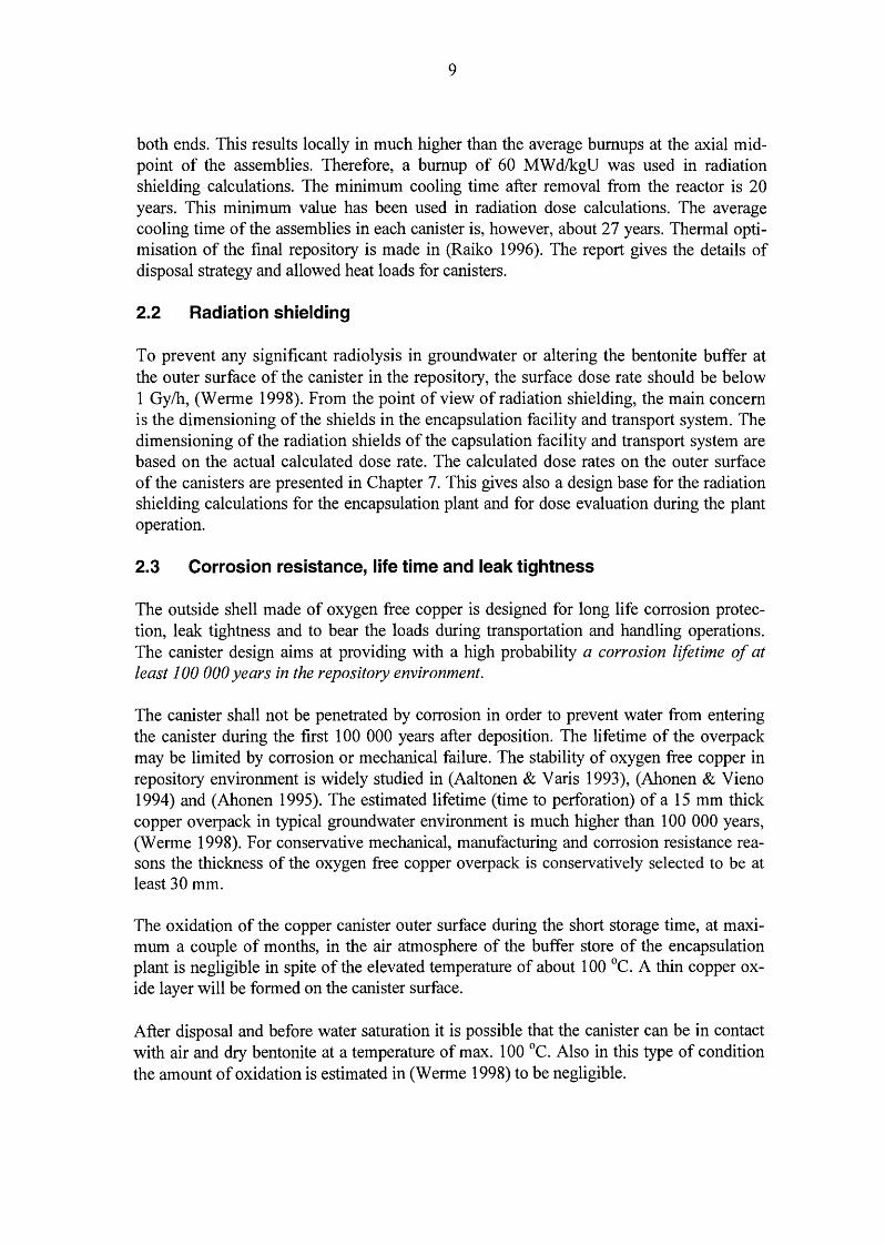
9
both ends. This results locally in much higher than the average burnups at the axial midpoint of the assemblies. Therefore, a bumup of 60 MW d/kgU was used in radiation shielding calculations. The minimum cooling time after removal from the reactor is 20 years. This minimum value has been used in radiation dose calculations. The average cooling time of the assemblies in each canister is, however, about 27 years. Thermal optimisation of the final repository is made in (Raiko 1996). The report gives the details of disposal strategy and allowed heat loads for canisters.
2.2 Radiation shielding
To prevent any significant radiolysis in groundwater or altering the bentonite buffer at the outer surface of the canister in the repository, the surface dose rate should be below 1 Gylh, (W erme 1998). From the point of view of radiation shielding, the main concern is the dimensioning of the shields in the encapsulation facility and transport system. The dimensioning of the radiation shields of the capsulation facility and transport system are based on the actual calculated dose rate. The calculated dose rates on the outer surface of the canisters are presented in Chapter 7. This gives also a design base for the radiation shielding calculations for the encapsulation plant and for dose evaluation during the plant operation.
2.3 Corrosion resistance, life time and leak tightness
The outside shell made of oxygen free copper is designed for long life corrosion protection, leak tightness and to bear the loads during transportation and handling operations. The canister design aims at providing with a high probability a corrosion lifetime of at least 100 000 years in the repository environment.
The canister shall not be penetrated by corrosion in order to prevent water from entering the canister during the first 1 00 000 years after deposition. The lifetime of the overpack may be limited by corrosion or mechanical failure. The stability of oxygen free copper in repository environment is widely studied in (Aaltonen & Varis 1993), (Ahonen & Vieno 1994) and (Ahonen 1995). The estimated lifetime (time to perforation) of a 15 mm thick copper overpack in typical ground water environment is much higher than 100 000 years, (Werme 1998). For conservative mechanical, manufacturing and corrosion resistance reasons the thickness of the oxygen free copper overpack is conservatively selected to be at least 30 mm.
The oxidation of the copper canister outer surface during the short storage time, at maximum a couple of months, in the air atmosphere of the buffer store of the encapsulation plant is negligible in spite of the elevated temperature of about 100 °C. A thin copper oxide layer will be formed on the canister surface.
After disposal and before water saturation it is possible that the canister can be in contact with air and dry bentonite at a temperature of max. 100 °C. Also in this type of condition the amount of oxidation is estimated in (Werme 1998) to be negligible.

10
The insert structure is designed to be leak tight only during the sealing process of the copper overpack. The seal welding of the copper lid is planned to be made in vacuum. In the postclosure safety analysis (Vieno & Nordman 1999) the insert is not assumed to provide any hindrance for the release of radionuclides.
The canister insert will be exposed to internal corrosion if the void in the insert is filled with air. The total void of the canister is about 0.6 to 0.96 m3 in VVER 440 and BWR type canister inserts, respectively. In addition, the water remains in the fuel and the air inside the canister insert may cause nitric acid formation with the assistance of irradiation. The nitric acid increases the risk for stress corrosion cracking (SCC). To avoid the risk, the canister atmosphere is planned to be replaced by inert gas (helium or argon) during encapsulation process, if the SCC-risk cannot be shown negligible by further investigations.
The massive insert structure made of nodular graphite cast iron is not prone to creep in disposal temperatures and, thus, the shape and size of the externally pressure loaded canister will remain stable.
2.4 Dimensional constraints
The size and shape of the canisters for B WR and VVER 440 fuel will be kept as close to each other as possible for manufacturing and operational reasons and standardisation. Both of the canister types have the same outer diameter and the lid design with the shoulder for the gripping device is identical. This is useful in manufacture and handling operations and minimises the need of special tools and equipment. The length of canister is, however, different for BWR and VVER 440 type fuel. Accordingly, the dead weight of the canisters varies. The holes for the assemblies in the canister insert have some tolerance to assure the installation of fuel assemblies without friction drag or risk of jamming when using the fuel handling machine in the encapsulation station. The maximum size of the canister is limited by the cooling capacity of the bentonite and rock surrounding the canister in the repository. The canister structure is dimensioned according to the required strength, radiation shielding and subcriticality properties, tightness and lifetime. Subcriticality is required even if the canister void space is filled with water.
2.5 Manufacturing tolerances
Manufacturing tolerances mean in this context dimensional (geometric) tolerances, alignment, roundness and surface roughness. The geometric design has been made so that the planned properties of the canister can be achieved with reasonable workshop tolerances, that do not require any special machining tools or processes.
The openings in the insert are designed so wide, that the alignment and dimensions achieved directly in the casting process are sufficient. Especially the square shaped openings for BWR fuel assemblies can not easily be machined, the surface of the openings is only cleaned by sand blasting. The nominal width of the opening is, at least, 5 mm more than the nominal width of the fuel assemblies. This tolerance allows reasonable inaccuracies in the shape of the openings caused by the casting process.

11
The machining tolerance of ±0.5 mm in diameter in cylindrical products with a typical diameter of 1 m and length of 4 m is achieved with a normal "good manufacturing practise". The nominal inside diameter of the copper overpack and the outside diameter of the insert has a nominal difference of 2 mm, which corresponds to a nominal 1 mm gap between the cylinders. This allowance will guarantee a free installation of the insert into the copper overpack.
The surface roughness requirement for the weld preparation of electron-beam weld between the lid and the cylinder is Ra = 3.2 Jlm according to (Aalto 1998).
2.6 Heat loads and allowable temperatures
The maximum operation temperature at the canister surface is limited to be below + 100 °C to assure the chemical stability of the highly-compacted bentonite in the disposal hole and to avoid the concentration of salt in the vicinity of the canister due to vaporisation of groundwater in the early years after the sealing of repository. The design temperature of the metal parts of the canister is set for the strength analyses, however, to + 120 °C to achieve a reasonable margin in required mechanical properties of the materials.
The decay heat generation in canisters will depend on the amount, burnup and cooling time of the fuel. The initial decay heat load in a canister will be between 1 and 2 kW. The thermal conductivity of the metal body of the canister is two orders of magnitude higher than the conductivity of the surrounding bentonite and rock in the repository. Therefore the metallic canister will be practically at a uniform temperature and all the thermal gradient will prevail in the bentonite and rock around the canister.
The allowable heat load per canister depends on the heat conductivity properties of the surrounding buffer and rock and the distance between neighbouring canisters in the repository. Heat conduction and thermal optimisation are studied and discussed in more detail in (Raiko 1996).
The highest fuel pin temperature inside the canister is calculated to be less than + 150 °C. This is calculated assuming radiation heat transfer and conduction through the gas between the fuel pins and the canister insert, when the canister surface temperature is + 1 00 °C. Thermal phenomena inside a canister are more closely analysed in (Raiko 1993) and (Rossi et al. 1999).
2. 7 Mechanical design load
The mechanical design load for the canister is 14 MPa external pressure. The design load consists of 7 MPa hydrostatic pressure (0.7 km water pillar) and a maximum of 7 MPa swelling pressure of bentonite according to (Werme 1998) and (Kamland 1998). The swelling pressure of 7 MP a corresponds to the dry bentonite density of 1590 kg/m3 or density of 2020 kg/m3 at water saturation. Both of the primary dimensioning pressure components are conservative estimates. The planned disposal depth is between 400 and 700 m below the ground surface in the bedrock. The swelling pressure of the buffer depends on the density of the bentonite-water mixture. The design pressure is assumed to be evenly

12
distributed and acting on all faces of the vessel. This is the basic design load in operating condition, case 1.
The insert with flat lids is also analysed in case of 0.1 MPa internal overpressure. This is the load case during the encapsulation process when the normal atmospheric pressure is prevailing inside the insert and the canister is in a vacuum chamber for the electron beam weld of the copper lid. This is case 2, see Figure 1.
The basic dimensioning calculations are performed for the normal operating conditions and in some upset conditions. The hydrostatic pressure loads are always evenly distributed, but the swelling pressure of bentonite may have some disturbances, especially in the early years after the sealing of the repository, when the bentonite starts to wet. These types of special loads are depicted in Figure 2, cases 3 to 5. All of these cases 3 - 7 do not have a real physical base, but they are very conservatively defined different type of load conditions.
The bentonite swelling pressure is assumed to be unevenly distributed also in the saturated condition, cases 6 to 7, see Figure 3. This kind of swelling pressure conditions may be due to a tilted canister in the disposal hole, variations of bentonite density, heterogeneous rock properties, or a curved disposal hole.
The strength of the canister is studied also with a postulated hydrostatic load during a glaciation. In this load case the groundwater pressure component 7 MPa is replaced by 34 MPa, which is the sum of 700 meter high pillar of groundwater and 3.0 km of ice (average density 900 kg/m3
) floating on the groundwater. In this extreme load case (p = 41 MPa, the sum of 700 meter groundwater + 3000 meter ice pressure + 7 MPa swelling pressure of bentonite) no additional safety margin is applied. This is case 8.
The integrity of the canister can be damaged due to shear type rock movements if the shear plane happens to intersect the deposition hole and the shear amplitude is large enough. When the bentonite buffer around the canister is 350 mm thick it can be estimated that the shear movements of the rock up to 1 00 mm can be tolerated without the direct break of the canister (SKB 1992). No completely verified analysis of the critical shear amplitude has, however, been presented due to very sensitive and complicated numerical modelling of the mechanical material behaviour of saturated bentonite under compression (Borgesson 1992). The risk caused by large rock movements, which may occur during the melting phase of a major continental glacier, is minimised by locating the disposal gallery outside major fracture zones in the bedrock. (Vieno & Nordman 1999).
The lifting equipment and the shoulder in the copper lid collar are dimensioned for the gravity load of the loaded canister multiplied by the dynamic factor of handling loads and required safety factor.

13
Case 1. Basic design load, external pressure of 14 M Pa
p (atmospheric) 0.1 M Pa
~:::::: :~~~:~~~~:~:::::: :~ Case 2. Internal pressure of 0.1 M Pa
FIGURE 1. Basic design pressure loads.
Fixed ends
L/1 0 p = 7 M Pa L/1 0
Case 3: Wetting phase, local excentric swelling pressure
Simple supports
L/1 0 p = 7 M Pa L/1 0
Case 4: Wetting phase, local excentric swelling pressure
Fixed one end
p = 7 M Pa
1 CANISTER
Case 5: Wetting phase, local excentric swelling pressure
FIGURE 2. Special local swelling loads postulated during wetting phase. Groundwater hydrostatic pressure is not present simultaneously.

14
p (swelling) 100%
120%
Case 6. Locally excentric bentonite swelling pressure
p (swelling) 100%
80%
100%
Case 7: A xi symmetric but variable bentonite swelling pressure
FIGURE 3. Special swelling pressure loads postulated in fully saturated phase. Groundwater hydrostatic pressure can be present simultaneously.
2.8 Allowable stresses and strains and required safety factors
Design stress
The design stress of the material in the basic dimensioning calculation is the yield strength in the design temperature divided by the required safety factor. The minimum yield strength of the manufacturing materials is given in material standards, e.g. in (SFS 3345) and (SFS-EN 1 0028-2).
Safety factors
Safety factor is the ratio of the design strength (usually the yield strength) and the actual allowable general membrane stress intensity. The stress intensity is a reduced stress, that is defined in stress analysis standard (SFS 3292) as the difference between the major and minor principal stress component. For pressure vessels made of steel the required safety factor is typically 1.5. For pressure vessels made of nodular cast iron the required safety factor in pressure vessel standards is typically 3.5- 4.5.
The disposal canister cannot be compared to a pressure vessel due to the fact that pressure vessels are designed for cyclic operation (usually thousands of operation cycles) whereas the disposal canister has only one or a few load cycles. This is why the fatigue control is not relevant. An other requirement, toughness, is not very relevant due to the fact that in the design load case the canister is loaded by external pressure only, which leads to compressive stresses in major parts of the canister. Keeping these facts in mind, the required safety factor in the design load case for membrane stress intensity is set to 2.0. The stress

15
state in the canister is typically compression in all three dimensions and the risk of elastic buckling is totally eliminated by the integral support structure, the bulkheads or separating walls of the insert.
The primary bending stress intensity is allowed to be 1.5 times the design stress according to (SFS 3292) that is typically adapted for pressure vessels designed by stress analysis.
For the steel lids the safety factor is taken conservatively as 2.0. According to the Finnish pressure vessel standard (SFS 261 0) the required safety factor for pressure vessel steel is 1.5 at minimum.
The safety factor for the stresses due to handling loads in copper vessel is taken 1.5 to avoid plastic deformation and residual stresses.
In addition, the strength of the structure is checked in many postulated upset conditions. These loads are caused by either local irregularities in bentonite swelling or ice age loading, which is conservatively assumed to cause an additional hydrostatic pressure by 3 km thick ice floating on groundwater. These load cases are specified in section 2.8, cases 3 to 8, see Figures 2 and 3. The canister is checked not to break or collapse due to these loads. Local plasticity and moderate irreversible deformation is allowed during the postulated upset load conditions in the canister structure, but the leak tightness shall not be lost. Reasonable margin against rupture or collapse in all upset load cases shall be verified.
2.9 Safety classification
Systems, structures and components important to safety shall be designed, manufactured , installed and operated in such a way that their quality level and the inspections and tests needed to verify their quality level are commensurate with the importance to safety of each item. The YVL-guide 2.1, published by the national authority, sets the principles and criteria of the classification.
According to the YVL-guide 2.1 components shall be assigned to safety class 2, if their failure to operate would cause a considerable risk of uncontrolled criticality. On the other hand, components shall be assigned to safety class 3, if their fault or failure would prevent decay heat removal from spent fuel, or cause the dispersal of radioactive material. The appendix of the YVL-guide 2.1 gives an example, that the storage racks for fresh and spent fuel are assigned to safety class 2 and the storage of spent fuel and liquid wastes, including pools and tanks, are assigned to safety class 3 .
From these rules and examples given in the YVL-guide it can be concluded that the canister for nuclear fuel disposal shall be classified to safety class 2.

16

17
3 MATERIAL SELECTION AND SPECIFICATION OF PROPERTIES
The insert is made of nodular graphite cast iron. The iron quality is selected in such a way that adequate strength is achieved and the ductility of the material can be maximised. The proposed quality is GRP-400 according to the Finnish national standard (SFS 2113). The manufacturing material, nodular cast iron, is selected instead of cast steel or welded steel structure due to its superior manufacturing aspects.
The material for the overpack is oxygen free high conductivity copper (Cu-OF according to the standard (SFS 2905)) with an addition of 40 to 60 ppm phosphorus. We call this micro alloyed quality in this report 'Cu-OFP'. The micro alloying is made to improve the creep strain properties of Cu-OF copper in higher temperature (+200 to +300 °C). Copper is selected as a corrosion protection layer due to its chemical stability. It is a very noble metal, it is available at reasonable cost, and it does not require an oxide film on the surface to withstand the corrosion as many other passive metals like titanium or aluminium do.
3.1 Specification of manufacturing materials
The insert is made of nodular graphite cast iron. The proposed quality is GRP-400 according to the Finnish national standard (SFS 2113). The quality corresponds to GGG-40 according to the German norm DIN 1693-73 or quality 0717-00 according to the Swedish SIS 1407 norm. The design strength of the GRP-400 quality is 250 MPa in room temperature and 240 MP a in design temperature + 120 °C. Minimum ultimate strength is according to the standard 400 MPa and the elongation to fracture 15% for section of 50 mm thick or less. Other relevant physical properties of the nodular graphite iron are: density 7200 kg/m3
, Young's modulus 170 GPa, Poisson's ratio 0.28, linear coefficient of thermal expansion 10 to 12·10-6 1!°C according to (SFS 2113) and (SFS 3345).
The flat covers of the insert are made of pressure vessel steel P265GH defined according to (SFS-EN 1 0028-2) or any equivalent quality. All the specified strength and ductility values are shown in Table 2.
TABLE 2. Minimum specified strength and ductility properties for nodular graphite cast iron GRP-400 and pressure vessel steel P265GH in room temperature and in design temperature (+ 120 °C). Respective typical properties for oxygen free copper are added on the bottom line for comparison.
Material Ultimate Elongation to Yield strength Yield strength quality strength fracture in +20 °C in +120 °C
(MP a) (o/o) (MP a) (MP a) GRP-400 400 15 250 240 P265GH 410-530 23 245 210 Cu-OF 200 50 50 45
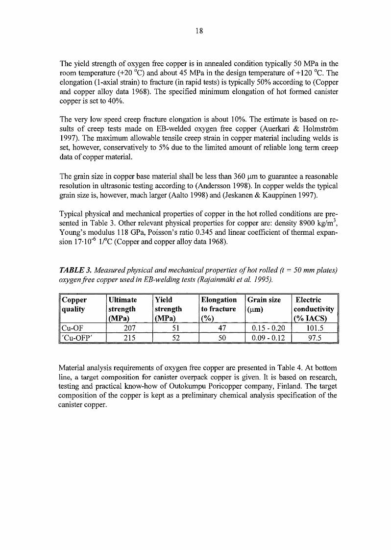
18
The yield strength of oxygen free copper is in annealed condition typically 50 MPa in the room temperature ( + 20 °C) and about 45 MP a in the design temperature of+ 120 °C. The elongation (1-axial strain) to fracture (in rapid tests) is typically 50% according to (Copper and copper alloy data 1968). The specified minimum elongation of hot formed canister copper is set to 40%.
The very low speed creep fracture elongation is about 1 0%. The estimate is based on results of creep tests made on EB-welded oxygen free copper (Auerkari & Holmstrom 1997). The maximum allowable tensile creep strain in copper material including welds is set, however, conservatively to 5% due to the limited amount of reliable long term creep data of copper material.
The grain size in copper base material shall be less than 360 1-lm to guarantee a reasonable resolution in ultrasonic testing according to (Andersson 1998). In copper welds the typical grain size is, however, much larger (Aalto 1998) and (Jeskanen & Kauppinen 1997).
Typical physical and mechanical properties of copper in the hot rolled conditions are presented in Table 3. Other relevant physical properties for copper are: density 8900 kg/m3
,
Young's modulus 118 GPa, Poisson's ratio 0.345 and linear coefficient of thermal expansion 17·10-6 lfC (Copper and copper alloy data 1968).
TABLE 3. Measured physical and mechanical properties of hot rolled (t =50 mm plates) oxygen free copper used in EB-welding tests (Rajainmaki et al. 1995).
Copper Ultimate Yield Elongation Grain size Electric quality strength strength to fracture (!-lm) conductivity
(MP a) (MP a) (o/o) (0/o IACS)
Cu-OF 207 51 47 0.15- 0.20 101.5 'Cu-OFP' 215 52 50 0.09-0.12 97.5
Material analysis requirements of oxygen free copper are presented in Table 4. At bottom line, a target composition for canister overpack copper is given. It is based on research, testing and practical know-how of Outokumpu Poricopper company, Finland. The target composition of the copper is kept as a preliminary chemical analysis specification of the canister copper.

19
TABLE 4. Standard requirements of oxygen free copper according to ASTM standard and a target composition ofCu-OFP.
Cu-specification I Contents S (ppm) 0 (ppm) p (ppm) H(ppm) Cu (0/o) ASTM UNS C10100, Cu-OFE ~15 ~5 ~3 - ;;::: 99.99 ASTM UNS C10200, Cu-OF - ~10 - - ;;::: 99.95 target composition of ~8 ~5 40-60 ~ 0.6 ;;:::99.99 'Cu-OFP' for canisters
3.2 Quality controls for the materials manufacture
The quality assurance of the canister material manufacture is to be carried out according to the normal procedures used in nuclear power plant component manufacture. The quality control plan shown on Table 5 is drafted accordingly. The material manufacturing operations are controlled to fulfil the requirements that are set in the design report. The examination procedure codes (type TM-Ot-xxx) are given as an example. They refer to the validated procedures used by Teollisuuden Voima Oy (TVO).
TABLE 5. Quality control plan for canister material manufacture.
EQUIPMENT: CANISTER FOR NUCLEAR FUEL DISPOSAL
Requirements for material manufacturing test reports:
Name of item: copper overpack
Chemical composition:
Grain size determination:
Tensile test:
Material identification:
Certificate* 1)
3.1B
3.1B
3.1B
3.1B
Name of item: nodular graphite cast iron insert and steel lids Certificate
Chemical composition: 3.1B
Tensile test:
Material identification:
*1) Test reports according to requirements of DIN 50049
3.1B
3.1B
Exam. procedure
TM-Ot-003
TM-Ot-004
TM-Ot-210
Exam. procedure
TM-Ot-003
TM-Ot-004
TM-Ot-210

20
21
4 CANISTER DESCRIPTION
4.1 General description and dimensions of the canister
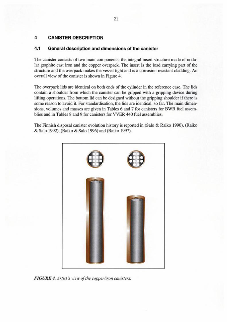
The canister consists of two main components: the integral insert structure made of nodular graphite cast iron and the copper overpack. The insert is the load carrying part of the structure and the overpack makes the vessel tight and is a corrosion resistant cladding. An overall view of the canister is shown in Figure 4.
The overpack lids are identical on both ends of the cylinder in the reference case. The lids contain a shoulder from which the canister can be gripped with a gripping device during lifting operations. The bottom lid can be designed without the gripping shoulder if there is some reason to avoid it. For standardisation, the lids are identical, so far. The main dimensions, volumes and masses are given in Tables 6 and 7 for canisters for BWR fuel assemblies and in Tables 8 and 9 for canisters for VVER 440 fuel assemblies.
The Finnish disposal canister evolution history is reported in (Salo & Raiko 1990), (Raiko & Salo 1992), (Raiko & Salo 1996) and (Raiko 1997).
FIGURE 4. Artist 's view of the copper/iron canisters.

22
TABLE 6. Mass and dimensional data of the canister for 12 BWR assemblies.
Cast Steel lid Copper Copper Fuel insert cylinder lid assembly
Outside diameter [m l 0.950 0.950 1.052 1.052 Wall thickness [m l 0.050 0.050 0.050 Len~h [m] 4.450 4.754* 4.398 Density [kg/m3
] 7200 7850 8900 8900 8555 Material volume [m3
] 1.7818 0.0354 0.740 0.052 0.0347 Mass [kg] 12829 278 6586 463 297 Number of items f-l 1 2 1 2 12 Total mass [kg l 12829 556 6586 926 3564
* Total length of the canister may vary depending on the lifting shoulder design in the lid.
TABLE 7. Mass and volume balances of the canister for 12 BWR assemblies.
Copper Steel or Fuel Void space Total iron assemblies
Mass [kg] 7512 13385 3564 - 24461 Volume [m3
] 0.844 1.853 0.416 0.956 4.069
TABLE 8. Mass and dimensional data of the canister for 12 VVER 440 assemblies.
Cast Steel lid Copper Copper Fuel insert cylinder lid assembly
Outside diameter fml 0.950 0.950 1.052 1.052 Wall thickness [m] 0.050 0.050 0.050 Length [m] 3.250 3.554* 3.20
Density fkwm3l 7200 7850 8900 8900 8168 Material volume [m3
] 1.353 0.0354 0.551 0.050 0.0262
Mass fkgl 9742 278 4903 463 214 Number of items [-] 1 2 1 2 12
Total mass [kg] 9742 556 4903 926 2568
* Total length of the canister may vary depending on the lifting shoulder design in the lid.
23
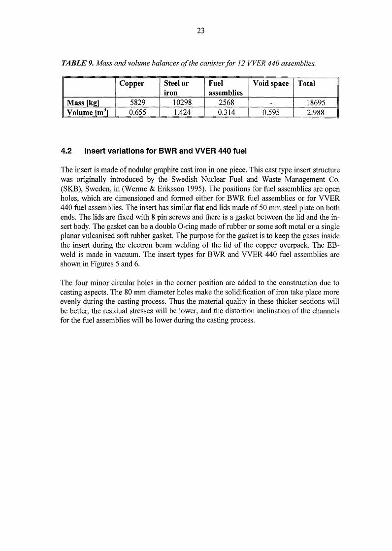
TABLE 9. Mass and volume balances of the canister for 12 VVER 440 assemblies.
Copper Steel or Fuel Void space Total iron assemblies
Mass [kg] 5829 10298 2568 - 18695 Volume _[m3J 0.655 1.424 0.314 0.595 2.988
4.2 Insert variations for BWR and VVER 440 fuel
The insert is made of nodular graphite cast iron in one piece. This cast type insert structure was originally introduced by the Swedish Nuclear Fuel and Waste Management Co. (SKB), Sweden, in (Werme & Eriksson 1995). The positions for fuel assemblies are open holes, which are dimensioned and formed either for BWR fuel assemblies or for VVER 440 fuel assemblies. The insert has similar flat end lids made of 50 mm steel plate on both ends. The lids are fixed with 8 pin screws and there is a gasket between the lid and the insert body. The gasket can be a double 0-ring made of rubber or some soft metal or a single planar vulcanised soft rubber gasket. The purpose for the gasket is to keep the gases inside the insert during the electron beam welding of the lid of the copper overpack. The EBweld is made in vacuum. The insert types for B WR and VVER 440 fuel assemblies are shown in Figures 5 and 6.
The four minor circular holes in the corner position are added to the construction due to casting aspects. The 80 mm diameter holes make the solidification of iron take place more evenly during the casting process. Thus the material quality in these thicker sections will be better, the residual stresses will be lower, and the distortion inclination of the channels for the fuel assemblies will be lower during the casting process.

CANISTER INSERT FOR BWR-FU EL
24
NODULAR CAST IRON INSERT FOR NUCLEAR FUEL DISPOSAL CANISTER
INSERT WEIGHT: 12.8 I 9. 7 ton INSERT LENGTH: 4.45/3.25 m INSERT Dl AM ETER: 0.95 m
CANISTER INSERT FOR VVER 440-FUEL
FIGURE 5. The schematic view-· of the inserts for BWR and VVER 440 fuel assemblies.

25
I nsert section for BWR-fuel 50
I nsert section for VVER 440-fuel 58
~ 0 .,...
FIGURE 6. The sections of the inserts for BWR and VVER 440 fuel assen1blies.

26
4.3 Encapsulation process
The canister is transferred into the hot cell of the encapsulation plant and the fuel assemblies are moved one by one from the storage rack through safeguards measurements into the positions in the disposal canister insert by the fuel handling machine. Finally the steel lid with gasket is installed, the gas atmosphere in the canister cavity is then, according to proposed procedure, changed to some inert gas and the lid fastening nuts are tightened with a manipulator. The inert fill gas proposed is helium or argon and the fill gas pressure is equal to the atmospheric pressure 0.1 MPa. The leak tightness of the lid gasket is tested. The schematic presentation of the encapsulation process is shown in Figure 7.
HOT CELL
)
EB-WELDING CHAMBER
ENCAPSULATION PROCESS SCHEME
TESTING
FIGURE 7. Schematic presentation of the encapsulation process.
4.4 Canister handling operations
LIFT
The canister is transferred into the hot cell of the encapsulation plant and the fuel assemblies are moved one by one from the storage rack into the positions in the canister insert by the fuel handling machine. Finally the steel lid with gasket is installed and the nuts are tightened with a manipulator. The gas atmosphere in the canister cavity is then changed. The air atmosphere inside the canister is changed to some inert gas. The inert fill gas proposed is argon or helium and the fill gas pressure is equal to the atmospheric pressure 0.1 MPa. The leak tightness of the lid gasket is tested. After accepted tightness test the canister in hot-cell is covered with a gas tight cover, the sealing system pressure in the seal between the canister and the hot -cell docking penetration is released, the canister is lowered to the transfer corridor, the copper lid is set on the top of the canister and the canister is

27
transferred to welding position for the sealing weld of the copper lid. The canister is transferred in the corridor on a railway trolley, which has a hoisting device.
4.5 Opening and unloading of the canister
In case of not achieving an acceptable copper lid weld after several repair attempts, or for some other reason, the copper canister can be machined open and the insert can then be opened in the hot cell. The copper vessel opening process takes place in the position, where the weld surface is also machined and the ND-examination for the lid weld is done. The same machining device is equipped with a narrow cutting tool and the copper cylinder is cut through the wall some centimetres below the EB-weld position. After this the copper lid can be lifted up and removed. Then the canister is moved back to the loading position in the encapsulation station and the screws of the inner steel lid are loosened and the lid is lifted up and removed. Now the fuel assemblies can be handled with the fuel handling device in the same way as during loading. All the fuel is removed and the empty canister is moved to decontamination. After decontamination the canister can be sent back to canister assembling workshop for further actions.

28
29
5 MANUFACTURING PROCEDURE
The canister is pre-fabricated in various workshops of subcontractors outside the encapsulation site. The canister components are manufactured, tested and quality controlled and then assembled. The assembled canister with one end open and the lids, screws and gaskets are transported to the encapsulation site, where the loading, final closing and final controls are made.
5.1 Pre-fabrication of the canister
The insert is cast in a foundry, and no separate thermal treatment is needed. The openings for fuel assemblies are formed to the cast body by setting an equivalent steel structure into the mould. The prefabricated structure is welded together from steel tubes with strict dimensional tolerances. After casting the block is cleaned up, cut into the right length and the outer surfaces are machined. Then a volumetric ND-examination is made. In addition, the dimensions and machined surfaces are examined. The lids are manufactured by machining from rolled steel plate. The pin screws are installed and the bottom lid with a gasket is assembled.
The cylinder of the overpack is manufactured either by welding hot rolled and bent copper plates together or by extrusion or pierce and draw process from a single cast and preheated billet. The cylinder is then machined. The copper lids are manufactured by casting a cylindrical billet, hot pressing and machining. The bottom lid is welded onto the cylinder. The pre-fabricated overpack is examined as for dimensions, surface roughness and unacceptable flaws.
The pre-fabricated components are then assembled together, the insert is put inside the copper overpack. The canister with loose top lids is transported to the encapsulation plant. A special cradle is used for handling and transportation of a pre-fabricated canister. Manufacturing processes of the canister components are described in more details in (Aalto et al. 1996) and (Aalto 1998).
5.2 Installation tolerances
The nominal inside diameter of the copper overpack is 2 mm larger than the outer diameter of the insert. This corresponds to a radial 1 mm gap between the cylinders. This is needed due to the fact that the machining of the inside of the large soft copper cylinder cannot possibly be made with more strict tolerances. An equal nominal gap ( + 2 mm axial tolerance) is also designed between the lids of the insert and the overpack.
The magnitude of the maximum (positive) strain in the copper material is evaluated in (Raiko & Salo 1992) to be about 2% in case the soft copper shell is plastically deformed the amount of the gap against the insert.

30
5.3 Quality controls for the pre-fabrication
The quality assurance of the canister pre-fabrication is to be carried out according to the normal procedures adapted for nuclear power plant component manufacturing. The quality control plan shown on Table 10 is drafted accordingly. The workshop operations in prefabrication are controlled to fulfil the requirements that are set in the design report. The examples of the named examination procedure codes (type TM-Ot-xxx) refer to the validated procedures used by Teollisuuden Voima Oy (TVO).
The copper plates or tubes are examined not to include large laminar defects by means of ultrasonic test before machining. The copper welds manufactured in workshop are examined by radiography and the weld surface is tested with liquid penetrant after machining. The acceptance criteria in volumetric examination are drafted according to existing standards, for example (SFS 23 79) or equivalent. The surface shall not contain detectable cracks.
The nodular graphite cast iron block is ND-examined before or after machining. The outer circumference is examined with ultrasonic test not to include large buried indications within the 50 to 60 mm depth measured from the outer circumference. The planar faces on the top and bottom end of the block are surface tested with liquid penetrant or magnetic particle examination for surface cracks.
The planar lids are surface tested for cracks.
5.4 Sealing weld of the canister lid
After loading and sealing of the insert, the canister is moved from the hot cell in vertical position to the electron beam welding position in a vacuum chamber. After evacuating the chamber and the canister, the copper lid is installed, fixed with a tool and welded. The welding is made in at least two phases, first a tag weld all around the lid to ensure the lid positioning during the full penetration weld. The positioning of the electron beam must be targeted to the lid seam with an adequately accurate tolerance during all the welding process. The positioning and the compensation of thermal deformations during the welding process is made with a programmed steering automation or mechanical steering device, which follows the pre-fabricated trail close to the seam to be welded. This kind of a local steering device allows the possible use of a front bar on the seam to give additional material to the weld and to minimise the surface craters caused by leaking of liquid weld metal. After welding the weld surface is machined and the weld is surface tested and NDexamined by radiography or ultrasonic equipment.
Figure 8 shows the details of the lid and lid weld construction. The optimal welding position of the copper lid with the procedures developed in the Finnish EB-welding development program is vertical according to the know-how and experience gained so far. The construction details may, however, change as a result of the continued procedure development. A program for the development of EB-welding for 50 mm thick copper was carried out in Finland in 1994 -1997. The results from welding tests are presented in (Aalto 1998).

31
TABLE 10. Quality control plan for canister pre-fabrication and assembly.
EQUIPMENT: CANISTER FOR NUCLEAR FUEL DISPOSAL
Requirements for component fabrication test reports:
Name of item: copper overpack
Visual inspection:
Dimensional test:
Material identification:
Ultrasonic test of the cylinders or rolled plates:
Final examination:
Name of item: nodular graphite cast iron insert
Visual inspection:
Dimensional test:
Material identification:
Ultrasonic test of the outer circumference:
Surface test of the machined end surfaces:
Final examination:
Name of item: steel lids
Visual inspection:
Dimensional test:
Material identification:
Surface test of the machined surfaces:
Final examination:
Name of item: copper overpack, EB-welds
Welding operator's performance qualification:
Weld process control:
Weld surface prefabrication:
Welding procedure qualification test:
Radiographic examination of welds *2):
Visual inspection of the welds:
Surface test for EB-weld surface:
Ultrasonic test *3):
*1) Test reports according to requirements of DIN 50049
*2) Workshop welds only
*3) Weld class WB (SFS 2379) for workshop welds
Certificate *1)
3.1B
3.1B
3.1B
3.1C
3.1C
Certificate
3.1B
3.1B
3.1B
3.1C
3.1C
3.1C
Certificate
3.1B
3.1B
3.1B
3.1C
3.1C
Certificate
3.1B
3.1B
3.1B
3.1C
3.1C
3.1B
3.1C
3.1C
Exam. procedure
TM-Ot-099
TM-Ot-202
TM-Ot-210
TM-Ot-123
Exam. procedure
TM-Ot-099
TM-Ot-202
TM-Ot-210
TM-Ot-123
TM-Ot-113
Exam. procedure
TM-Ot-099
TM-Ot-202
TM-Ot-210
TM-Ot-113
Exam. procedure
TM-Ot-100
TM-Ot-102
TM-Ot-103
TM-Ot-104
TM-Ot-106
TM-Ot-111
TM-Ot-123

32
01052
0802 I 50 50 :< -r---....,....-------,........-----........ - ----
MAX5
50 EB-weld
50
50
2
50
·=.:::;:.::·
FIGURE 8. The details of the lid construction, vertical seal weld and dimensions.
5.5 Sealing weld quality control
After EB-welding in the encapsulation plant the weld surface and possible front bar is machined to get a clean and even surface. The seal weld quality requirements are set in Table 11.

33
The outer surface of the weld is examined with a magnetic particle examination device or liquid penetrant testing or visually by optical TV -devices to detect surface flaws. The weld itself is examined with an ultrasonic device. The weld is examined with a scanning ultrasonic device, single or multi-channel type. To make the ultrasonic test with a manipulator, the top part of the welded canister is surrounded with a leak tight collar, which is then filled with water. The ultrasonic detectors are running in the water pool thus getting a good sound contact with the body to be detected. The use of water as a contact media makes it easier to keep the canister surface clean before disposal. If the EB-weld for the lid is made in vertical position, as shown in Figure 8, the ultrasonic testing can be made radially from the cylindrical outer surface of the vessel. Both normal incidence and angle beam probes can be used.
TABLE 11. Quality control plan for canister lid sealing weld.
EQUIPMENT: CANISTER FOR NUCLEAR FUEL DISPOSAL
Name of item: copper overpack, lid EB-weld
Welding operator's performance qualification:
Weld process control:
Weld surface prefabrication:
Welding procedure qualification test:
Visual inspection of the welds:
Surface test for EB-weld surface:
Ultrasonic test *1):
* 1) Weld class WD (SFS 23 79) for the lid sealing weld
Certificate * 1)
3.1B
3.1B
3.1B
3.1C
3.1B
3.1C
3.1C
Exam. procedure
TM-Ot-100
TM-Ot-102
TM-Ot-103
TM-Ot-104
TM-Ot-111
TM-Ot-123
An additional test possibility is the use of Computed X-ray Tomography (CT) to verify the canister EB-weld integrity. The actual wall thickness of 50 mm copper is beyond the capability of the equipment available today. However, the use of this method is under consideration.
CT creates cross section images by projecting a thin-beam x-ray through one plane of an object from many different angles. As the X-rays pass through the object, some radiation is absorbed, some is scattered, and some is transmitted through the object.
The radiation transmitted through the object at each angle is measured and referred to as attenuation data. It is a measure of the reduction in X-ray intensity that results from absorption and scattering by the object.
In CT scanning, the attenuation data is summed over the many different angles from which it is collected using a computer in a method called, reconstruction. Reconstruc-

34
tion essentially "builds" the CT image from the data collected and represents a cross section of the object.
CT scanners typically consist of 4 hardware subsystems: a radiation source, a radiation detector system, a mechanical manipulator, and a computer with display. The radiation detector system is composed of detection elements, such as scintillating crystals and photodiodes. A data acquisition system (DAS) measures radiation data transmitted through the object and digitises it into a format that can be handled by the scanner's computer system.
A mechanical manipulator is needed to precisely move the object relative to the X-ray source and detector system. Finally, aCT system requires a computer to control the scan motion and the timing of data acquisition. The computer then also reconstructs the image from raw scan data.
5.6 Repair procedures
If the ND-examination result of the lid weld is not acceptable, the EB-weld can be repaired by making a new weld in a partial or total circumference of the weld. This means that the defected area of the weld is re-melted and solidified.
In case of not achieving an acceptable copper lid weld after several repair attempts, or for some other reason, the canister can be technically opened. Opening and unloading of the canister is described in chapter 4.5.

35
6 MECHANICAL AND THERMAL-MECHANICAL DIMENSIONING
The mechanical strength of the canister is checked in load conditions specified in Section 2. 7. The insert structure is checked in design pressure load cases to have a reasonable margin (safety factor 2) in general membrane stresses when compared to the material design strength (yield strength) in the design temperature. Secondly, the structure is checked in postulated upset load conditions (special local bentonite swelling loads during wetting phase, non-symmetric swelling loads in saturated phase, and the extreme pressure load during ice age) to have a reasonable margin against collapse failure.
In addition, the copper overpack is checked to withstand the lifting and handling device loads during encapsulation, transport and disposal operations.
6.1 Strength analysis of the insert
Design pressure loads, cases 1 and 2
The insert is dimensioned in two basic design load cases:
1. external pressure 14 MPa (the sum of7 MPa pressure of the 700 m groundwater and 7 MP a pressure of the expanding bentonite), and
2. internal pressure 0.1 MPa (during the vacuum of the lid EB-weld).
The load cases 1 and 2 are first checked according to the Finnish pressure vessel norm (SFS 2862) and (SFS 2611), respectively. Load case 2 leads to a very low stress in the cylinder, less than 1 MPa. In load case 1 the integral structure is conservatively modelled for manual calculation as a cylinder continuously stiffened against unstable buckling. The required minimum wall thickness (s) of the cylinder is calculated according to (SFS 2862) formula (1) as follows:
where
p·D0
·n s=
2 · O"o.2 '
p is the external pressure (14 MPa), Do is the outside diameter of the cylinder (0.950 m), n is the safety factor (2.0), and
(1)
cro.2 is the yield strength of the material in the design temperature (240 MPa).
The required wall thickness is obtained to be s =55 mm. The actual 'equivalent cylinder' wall thickness is about 120 mm in both of the canister variants, see Figures 6 and 9. The equivalent wall thickness is defined by summing the load bearing section thicknesses in the weakest section of the insert, e.g. the sum of the thickness of the bulkheads and the outer circumference 25 mm+ 50 mm+ 50 mm for BWR-type insert. The measure 25 mm is the half of the 50 mm bulkhead at the centre.
36
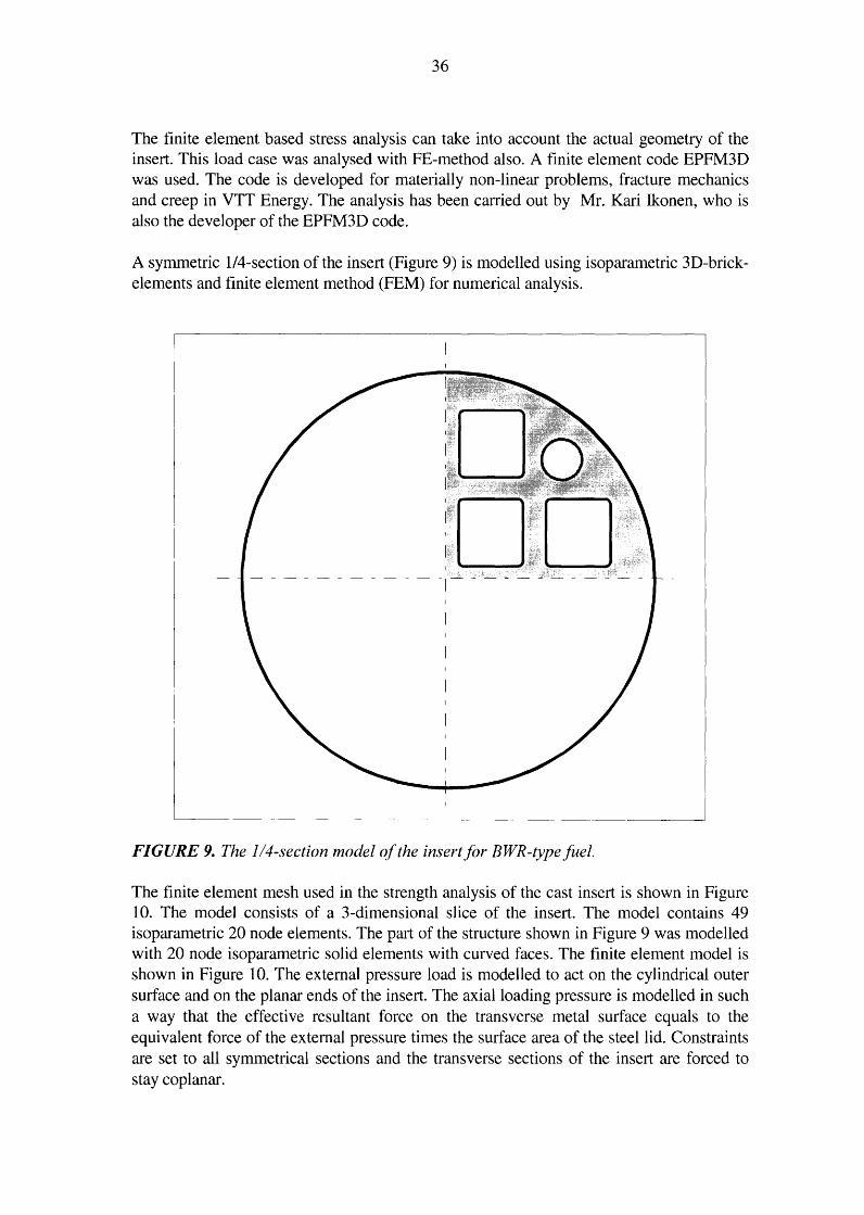
The finite element based stress analysis can take into account the actual geometry of the insert. This load case was analysed with FE-method also. A finite element code EPFM3D was used. The code is developed for materially non-linear problems, fracture mechanics and creep in VTT Energy. The analysis has been carried out by Mr. Kari Ikonen, who is also the developer of the EPFM3D code.
A symmetric 114-section of the insert (Figure 9) is modelled using isoparametric 3D-brickelements and finite element method (FEM) for numerical analysis.
FIGURE 9. The 114-section model of the insert for BWR-typefuel.
The finite element mesh used in the strength analysis of the cast insert is shown in Figure 10. The model consists of a 3-dimensional slice of the insert. The model contains 49 isoparametric 20 node elements. The part of the structure shown in Figure 9 was modelled with 20 node isoparametric solid elements with curved faces. The finite element model is shown in Figure 10. The external pressure load is modelled to act on the cylindrical outer surface and on the planar ends of the insert. The axial loading pressure is modelled in such a way that the effective resultant force on the transverse metal surface equals to the equivalent force of the external pressure times the surface area of the steel lid. Constraints are set to all symmetrical sections and the transverse sections of the insert are forced to stay coplanar.

37
U ISU3D UTT Energy 16 th FEB 99 INI<R (J. D
FIGURE 10. The 3-dimensional finite element mesh of the 1/4-section of the insert for BWR-type fuel. The model is made very coarse, because the local compressive peak stresses in the rounded corners of the square openings are of no interest when there are no cyclic loads and no risk for fatigue.
The corresponding stress analysis is reported in Appendix A. The numerical threedimensional stress analysis shows that the stress intensity level in case 1 is very low, in average about 35 MPa in the circumference, see Figure 3 in Appendix A. When assessing the stress intensity results of the numerical analyses one should keep in mind that the canister insert is in compressed condition in all the three dimensions simultaneously due to external pressure load. Furthermore, the numerical stress analysis result shows that the stiffening and load bearing effect of the internal bulkheads of the iron insert is very remarkable.

38
Non-symmetric and bending loads, cases 3 to 7
The section properties of the cast insert relevant for bending strength are presented in Table 12.
TABLE 12. Sectional properties of the cast insert.
Sectional area Section modulus Flexural rigidity A_{m2
) W(m3) I (m4
)_
BWR -tyl!_e insert 0.40042 0.05633 0.02676
VVER 440 1YI!e insert 0.41634 0.05671 0.02694
The maximum bending stress in the insert can be calculated according to the linear beam theory from the bending moment according to formula (2)
where M is the bending moment in the section, and W is the section modulus.
(2)
The ultimate loading capacity of a beam in the bending case can be calculated according to formula (3)
where Mu is the ultimate bending moment capacity, W is the section modulus, cru is ultimate strength (400 MPa), and
(3)
<1> is the rupture factor of the bending beam (1.35 for thick walled cylinder).
Using the above formula for the ultimate bending capacity of a beam we get the ultimate bending capacity of the insert Mu= 400 MPa · 0.05633 m3
· 1.35 = 30.42 MNm.
The bending effect in load cases 3 to 6 can be calculated from the actual maximum bending moment of the case and the section modulus given in Table 12. The bending stress results are presented in Table 13. The yield stress is exceeded remarkably only in case 5, but even in that case the ultimate bending capacity (at ultimate strength 400 MPa) is not reached. The stiffening effect of the copper cylinder is conservatively ignored. As discussed in chapter 2. 7, the load cases 3 to 7 are very conservative assumptions, because the bentonite is assumed to be able to anchor the canister rigidly.

39
TABLE 13. Bending moment and bending stress (according to linear beam theory) in load cases 3 to 6. Legend: L = length of the canister 4. 8 m, D = outside diameter of the canister 1. 052 m, and p = specified maximum bentonite swelling pressure 7 MP a.
Load case Maximum bending Maximum bending Maximum bending moment moment (MNm) stress (MP a)
3 1 I 12 · p · D · ( 4/5 · L )7 9.0 160 4 118 · p · D · ( 4/5 · L )7 13.6 241
5 1 /2 · p · D · ( 1/2 · L )'1 21.2 376
6 0.2 · 1116 · p · D · L7 2.1 37.7
Load case 7 (see section 2.8, Figure 3) is the only one, that possibly causes some other stresses than pure compression to the copper overpack. If we consider the axial force balance (in load case 7) between the ends of the canister, we see that the unbalance must be compensated by axial friction forces between bentonite and copper overpack. The unbalanced reaction force between the ends in this case is
where
(4)
~F is the unbalanced axial force, ~p is the pressure difference (20% of the maximum bentonite swelling
pressure 7 MPa) between the ends, and D is the outside diameter of the canister overpack (1.052 m).
We get the unbalanced force ~F = 1.22 MN. If we conservatively ignore the friction between the copper overpack and the inside insert structure, we can presume that the unbalanced force is transferred by the copper overpack only. The maximum possible axial stress in copper overpack in this load case is the unbalanced force divided by the sectional area of the copper cylinder. We get the maximum axial stress of 7.8 MPa. This is a very low stress when compared to the copper yield strength (45 MPa) in the design temperature. The unbalanced axial force is, in practice, balanced by the friction between the copper cylinder and the iron insert, which causes some shear stresses on the copper cylinder. However, these are one or two orders of magnitude lower than the axial stress and can be thus ignored.
Ice load, case 8
The extreme loading condition, case 8, external pressure 41 MPa (hydrostatic pressure of 7 MP a+ bentonite swelling pressure of 7 MP a + extra hydrostatic pressure of 27 MP a due to three kilometres of ice) is checked not to cause a collapse failure of the canisters.
This load case can be analysed by numerical methods. The linear-elastic finite element calculation of the ice load case, load case 8, was made and the stress intensity result is shown in Figure 4 in Appendix A. The resulting average stress intensity is about 1 00 MP a

40
in the circumference meaning that even in this case the safety factor against global collapse is more than 2.
Analysis of collapse load
In addition and for comparison, the collapse load of the insert was assessed with the same finite element model and program. The extreme load case leads to limited plasticity in the insert structure. The material behaviour is modelled in this ultimate case including the post-yield condition. The critical measures in this kind of analysis are the maximum strain and the maximum deformation.
The limit load analysis for the insert structure was made with finite element method using non-linear (elastic-plastic) material modelling. Limit load means the pressure load that starts the plastic collapse of the insert structure.
The yielding and strain hardening material behaviour was modelled with RambergOsgood stress-strain relation based on the yield (240 MP a at + 120 °C) and ultimate strength (400 MPa) and respective maximum plastic strain (15%) of the cast material. The load, external pressure, was incrementally increased acting on the model surface. The nonlinear analysis was continued in 22 load increments as far as to 110 MP a external load. The stepwise balance iteration converged with all increments. The ratio between load and maximum displacement was very stable until about 100 MPa pressure and after that the displacements started to increase more rapidly. However, the analysis was stable with 110 MPa external load but the maximum radial displacement was more than 2.5 mm and the cylindrical shape of the insert was deformed to more polygon-like. As far as the iteration is converging the strain state is stable and the load carrying capacity is not exceeded.
The results show that the pressure load carrying capacity of the cast insert is at least about 100 MPa, see Figure 2 in Appendix A. This gives a safety factor of more than two against collapse even in load case 8, ice load during glaciation.
The element mesh was intentionally not detailed enough to model the rounded corners of the openings. Thus the openings were conservatively modelled as sharp squares. The singularity of the sharp corners of the FEM -mesh gives some extra local stress concentration but the effects of stress concentrations are vanishing when wide plasticity is present in the elastic-plastic collapse analysis. The stresses in the sharp corners remain compressive even in case of slightly asymmetric load.
The collapse analysis was made for the canister insert for BWR fuel assemblies. The structure and material for the insert for VVER 440 fuel assemblies is mechanically so identical that no separate analysis was seen necessary for that special structure.
The FEM-analysis was made with Silicon Graphics Indigo workstation. The number of degrees of freedom of the model is 969, and the number of effective elements in the stiffness matrix is 203 255. The non-linear solution was made in 22 load increments and the balance between loads and stresses was iterated during each of the load increments. The required processing time for one non-linear analysis was about 400 seconds.

41
6.2 Flat cover dimensioning
The mechanical strength of the flat cover is checked in three (of the eight) relevant load cases:
1. external pressure 14 MP a (7 MP a pressure of the groundwater + 7 MP a pressure of the expanding bentonite)
2. internal pressure 0.1 MP a (during the vacuum of the lid EB-weld), and
8. external pressure 41 MP a (extreme loading condition during ice age, canister temperature +20 °C, no safety factor requirements).
The flat cover is made of pressure vessel steel P265GH according to (SFS-EN 1 0028-2). The yield strength of the steel is 245 MPa in room temperature and 210 MPa in the design temperature + 120 °C. Flat covers are dimensioned according to the Finnish standard (SFS 2615). The safety factor used for design load is 2.0 that is more than the pressure vessel standard requirement 1.5. The required cover plate thickness is calculated according to the formula (5):
where
(5)
C is 0.35 (constant depending on the lid joint type), a is side length of the square opening (mm), z is a shape factor of the opening (1.0 for circle, 1.1 for square) p is the loading pressure (14 MPa), n is the safety factor (2.0 in design condition), cry is the yield strength of the material (210 MPa) in the design temperature,
and s is the required plate thickness (mm).
In the case of external pressure the dimension (a) is the size of the square openings of the cast insert, 155 mm. In case of internal pressure (case 2) the supporting structure diameter (a) is equal to the gasket diameter 900 mm and the shape factor of a circle is 1.0.
In load case 1 we get the minimum dimension for the steel lid thickness s = 21.8 mm and in case 2 thickness s = 9. 7 mm. In load case 8 the required lid thickness without safety factor is s = 45.1 mm. In this extreme load case the calculational safety factor is still 1.11 for the lid thickness and thus the case is lower than yield load and very far from rupture load.

42
6.3 Screws and gasket of the flat ends
The flat cover screws are loaded only in the internal pressure load case, load case 2 according to 5.2:
2. internal pressure 0.1 MP a (during the vacuum of the lid EB-weld).
The sum of the loading force, that is acting on the screws is calculated according to the formula (6):
where p D
(6)
is 0.1 MPa, and is the average diameter of the gasket (0.900 m).
The formula gives F = 0.0636 MN = 63.6 kN. The force is divided by the number of screws (8) and thus the force acting on a single screw is 63.6 kN I 8 = 8 kN.
The designed screws are M 16x2 and the strength class 8.8. The area of the load bearing section of the M 16 screw is 157 mm2 and the yield strength of the material is 640 MP a. The actual stress in the screws in the load case 2 is 8 kN I 157 mm2 =51 MPa, which leads to a safety factor of 12.5. The required safety factor for screws is 1.5 (SFS 2610).
6.4 Copper overpack and the lifting shoulder
The canister is handled either by supporting through the bottom end or by hanging from the top end shoulder in the copper lid. In the following the strength of the shoulder is verified. The shoulder is calculated as a cantilever beam, whose length is 25 mm and height is 30 mm, the load bearing width is assumed to be 75% of the circumference. The total width or circumference of the shoulder is 2.52 m. Thus the grip is assumed to load the length 75%·2.52 = 1.89 m of the circumference. The shape of the shoulder is shown in Figure 11.
The maximum shear mode and bending mode stresses are calculated at the root of the cantilever. The maximum shear stress is calculated according to the formula (7)
F·f F·f r------
- A - b·h' (7)
where F is the maximum weight of the canister (240 kN), f is the additional dynamic load factor (1.3) A is the sectional area of the loaded part of the shoulder, b is the load bearing width of the shoulder circumference (1.89 m), and h is the section height of the shoulder (0.03 m).
The resulting maximum shearing stress is t = 5.5 MPa.

43
01052
30r Loading fore~-; f-!--R-1-0-,~ :
The weakest section
I I
I
50
I I
I I
~
~ --------------
FIGURE 11. The details of the shoulder for the lifting grip and the dimensions.
50
The maximum bending stress is calculated assuming that all the dead weight load is concentrated onto the inner edge of the shoulder, see Figure 11. The bending stress component is calculated according to the formula (8) for cantilever beam:
M F·f·l (J'h = w = b. h2 '
(8)
6
where M is the bending moment in the section, W is the section modulus, F is the weight of the canister (240 kN), f is the additional dynamic load factor (1.3), 1 is the distance of the acting force from the section (0.025 m), b is the load bearing width of the shoulder circumference (1.89 m), and h is the height of the shoulder section (0.03 m).
The resulting maximum bending stress is crb = 27.5 MPa.
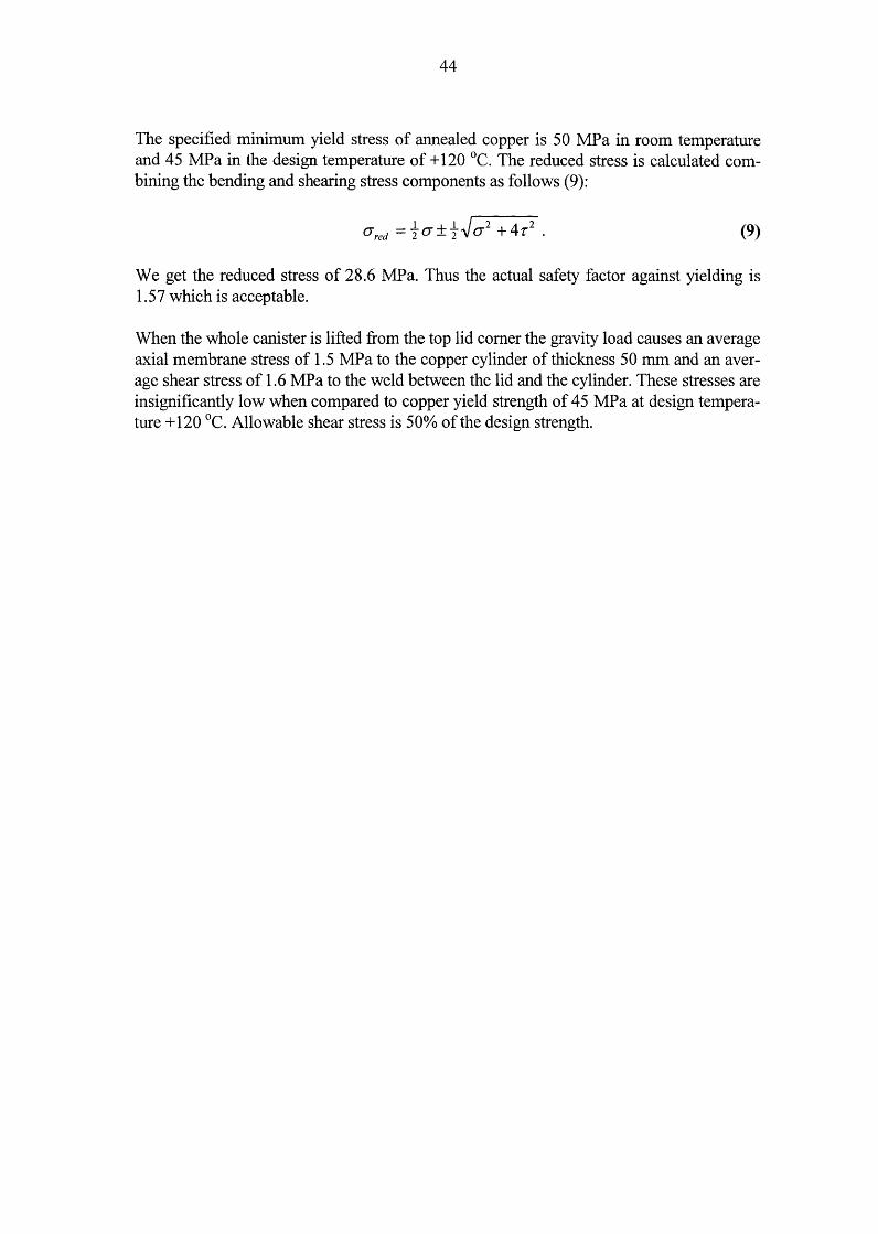
44
The specified minimum yield stress of annealed copper is 50 MPa in room temperature and 45 MP a in the design temperature of+ 120 °C. The reduced stress is calculated combining the bending and shearing stress components as follows (9):
- .l + .l.J 2 4 2 a red - 2 a - 2 a + r . (9)
We get the reduced stress of 28.6 MPa. Thus the actual safety factor against yielding is 1. 57 which is acceptable.
When the whole canister is lifted from the top lid corner the gravity load causes an average axial membrane stress of 1.5 MP a to the copper cylinder of thickness 50 mm and an average shear stress of 1.6 MPa to the weld between the lid and the cylinder. These stresses are insignificantly low when compared to copper yield strength of 45 MPa at design temperature+ 120 °C. Allowable shear stress is 50% of the design strength.

45
6.5 Operation temperature
The typical maximum temperature of a disposal canister in the repository is presented in Figure 12. The maximum temperature is reached within 20 years after the disposal. The canisters are planned to be emplaced in disposal holes in tunnels with a span of 7.5 to 8.0 m depending on the rock properties. The distance between parallel tunnels is 25 m. Thermal dimensioning and optimisation of the repository is made in (Raiko 1996). The maximum increase in the interface temperature of the canister surface and the bentonite is given in Figures 13 and 14 as a function of the surrounding rock thermal conductivity (A.) for both the canister types.
MAXIMUM TEMPERATURES IN REPOSITORY
100
90
80 . -· . -. -.. . . . .... ... . . . . . ..
. . . .. . . -··· .
70 . ' . ..-.. 60 u 50 ._, ~
40
30
r---- ' . ~------ ---- .,
,-' ~ -~ -~ ~---~ ,. . ' v~ ~
, ,., - - · · - · - CANISTER '. ~ ,-- ~ SURFACE ~ _.....-----DISPOSAL HOlE
20 EDGE
ROCK BETWEEN 10 TUNNELS
0 I I I I
1 2 5 10 20 50 100 200 500 1000 2000
TIME (a)
FIGURE 12. The maximum temperature of a disposal canister and near-field materials. The initial temperature of the ambient rock is assumed to be + 10 °C that is a typical value in Finland in depth of 5 00 m. The canister surface temperature is calculated with dry bentonite properties. The bentonite is assumed to be in contact with the canister outer surface. If the bentonite is or becomes water saturated, the gap between the canister surface temperature and the disposal hole edge temperature will be reduced by 50%. The hole edge and rock temperatures are not dependent on the bentonite condition.

90
85
75
70
46
MAX SURF ACE TEMPERATURE INCREASE IN BWR CANISTER
lambda=3.0 ~
~ -- - - - - lambda=2.7 ~ .. -~
~~~ -........... --~ ~ -- .. ............... ~
-- -- - - .. ............ ---~ --. - - -r----------- -7 8 9 10
Span between canisters in the repository (m)
FIGURE 13. The maximum temperature increase in BWR canister/bentonite interface.
90
85 ,-... u "-"
~ 80 ..... -~ "'C
75
70
MAX SURF ACE TEMPERATURE INCREASE IN VVER 440 CANISTER
lambda=3.0 ---- - - - - lambda=2.7 .. .. '-
. ~ ~-
~---~
~ - --~~ -~ ~
- .. -~ ----- -r--- - ---............. r---._ ....... --
-~ 7 8 9 10
Span between canisters in the repository (m)
FIGURE 14. The maximum temperature increase in VVER 440 canister/bentonite interface.
47
6.6 Cooling properties of the inserts
The decay heat generation in canisters depends on the amount, burnup and cooling time of the fuel. The initial decay heat generation in a BWR canister will be 2 kW or less and 1.4 kW or less in a VVER 440 canister.
The highest fuel pin temperature inside the cast insert type canister with 12 assemblies is calculated to be about + 150 °C. This is calculated conservatively assuming only radiation heat transfer and conduction in gas with air properties but ignoring possible effects of convection between the fuel pins and the canister insert. If the void inside the canister is filled with helium, the thermal conduction will be even better between the fuel pins and the iron insert. This would lead to even lower fuel pin temperatures (Rossi et al. 1999).
6. 7 Thermal stresses and deformations
The thermal conductivity of the metal body of the canister is two orders of magnitude higher than the conductivity of the surrounding bentonite and rock in the repository. This is why the metallic canister will be practically in an uniform temperature and the whole thermal gradient will prevail in bentonite and rock around the canister.
The same type of cooling condition situation prevails when the canister is stored in natural air cooling conditions immediately after loading in the encapsulation plant. The canister body temperature will rise about 25 °C above the ambient temperature within a couple of days according to calculation in (Rossi et al. 1999). The minimal thermal gradient in the metallic canister body will cause no significant stresses.
The bimetallic structure of the canister will react on the temperature increase as follows: the copper overpack will expand more than the iron insert due to the higher thermal expansion coefficient. The nominal gap between the insert and the overpack is 1 mm in radius after manufacture in room temperature. When the operation temperature stays below + 100 °C the gap will be increased not more than about 20%. If the temperature of the canister is below room temperature the gap will decrease. However, the nominal gap cannot vanish totally due to thermal deformation, because the temperature should then theoretically be below absolute zero.
6.8 Creep strains caused by shrinking in cooling period
The canisters reach their maximum temperature in the repository within 20 years after the disposal. A typical maximum temperature history is shown in Figure 12. The calculated canister temperature assumes conservatively that the bentonite around the canister is in dry condition. If the bentonite buffer is water saturated before the maximum temperature is reached, the value of maximum temperature will be some 15 °C lower.
Now we presume that simultaneously when reaching the maximum temperature the canister overpack is deformed due to creep or plastic deformation under the external pressure load. As a result of these deformations all the radial 1 mm gap between the cylindrical overpack and insert is closed. The copper overpack will be deformed until a full contact is

48
reached on all surfaces between the overpack and the iron insert due to the possibly very slowly increasing external pressure load. The actual maximum local strain in the copper overpack will be about 2% according to (Raiko & Salo 1992) when the 1 mm radial gap between the overpack and the insert is forced to close due to creep (or plastic) deformation caused by external pressure load.
The temperature of this bimetallic structure is then cooled within a few thousands of years from the maximum of+ 100 °C to about + 10 °C. The temperature decrease will cause now a tensile strain into the copper overpack due to the fact that the copper is shrinking more than iron when the temperature is decreasing, which can be estimated with the formula (10)
where
(10)
~E is the increase of the tensile strain ~ T is the temperature change of the system (1 0 - 100 = -90 °C), and ~a is the difference of linear thermal expansion coefficients of the materi
als in the overpack and canister insert (17 ·1 o-6 -11·1 o-6 = 6·1 o-6 1fC).
We get ~E = 0.00054 = 0.054%, which is of no importance when compared to the allowable creep strain in copper (5%).

49
7 RADIATION SHIELDING
Gamma and neutron dose rates on the outer surface of the canisters have been calculated with the Monte Carlo code MCNP and the point kernel code MARMER. The two canister types, one for the square BWR fuel assemblies and the other for the hexagonal VVER 440 fuel have been analysed in (Anttila 1998). A summary of the calculation results is shown in Tables 14 and 15.
TABLE 14. Average gamma dose rates at the axial middle level on the outer surface of the canisters.
Cooling time of the fuel assemblies assumed to be 20 years. Flux-to- Average dose conversion factors based on the AN SI/ ANS-6.1.1-1991 standard gamma applied. dose rate
(mSv/h) Rounded results from the MCNP4B calculations. BWR canister, discharge bumup 60 MWd/kgU 116 VVER 440 canister, discharge bum up 60 MW d/kgU 136
TABLE 15. Average neutron dose rates at the axial middle level on the outer surface of the canisters.
Cooling time of the fuel assemblies assumed to be 20 years. Flux-to- Average dose conversion factors based on the ICRP-74 report applied. neutron
dose rate Rounded results from the MCNP4B calculations. (mSvlh) BWR canister, discharge bumup 60 MWd/kgU 14 VVER 440 canister, discharge bum up 60 MW d/kgU 9
The average dose rates on the outer surface of the BWR canister are a little lower than those outside the VVER 440 canister. The variation of the dose rate on the canister surface is large, the local maximum rate is typically twice the average rate, see Figure 15. The maximum radiation dose rate on the surface of the canister ends is similar as on the cylindrical surface.

50
Gamma dose rate on the canister smface in a symmetric 45 degree sector
250~--------~--------~--------~--------~--~
, :2 200 +------+----;;;;•.....::...'---~---~:----+-----t-----1 ~ •' e '-" ~I ~ 150 +---~~--~~~--~---~-+-----~-~ ~ ~ .. ~ ~ 0 ~ 100 -+----21'c..._--+------t-----~!lr-----+----l ~ Oll ~ .. ~
--BWR canister ~ 50 -+-------1
- - - - VVER 440 canister
0 +---------~--------~----------+---------~--~
0 10 20 30 40
Azimuthal angle (degrees
FIGURE 15. The calculated average dose rate on the outer surface of the BWR and VVER 440 disposal canister. Discharge burnup is 60 MWdlkgU, cooling time 20 years, nominal canister geometry, 12 fuel assemblies.

51
8 CRITICALITY SAFETY
Subcriticality analyses are reported in (Anttila 1999). A canister used for final disposal of nuclear fuel must be subcritical also under very unfavourable conditions, i.e. for instance, when:
• the fuel in the canister is in the most reactive credible configuration,
• the moderation by water is at its optimum and
• the neutron reflection on all sides is as effective as credibly possible.
The criticality safety criteria require that the effective multiplication factor of the system studied is less than 0.95. If the calculation methods are not thoroughly enough validated or if the codes applied are known to predict too low values for reactivity, then the limit shall be even lower.
Concerning the criticality safety calculations of the disposal canisters the application of the so-called bumup credit would be a reasonable procedure, because the canisters are planned to be filled with irradiated fuel assemblies. However, all the calculations were carried out for the fresh fuel assemblies. Besides, the presence of burnable absorbers were omitted in the case of the BWR canisters
According to the results of MCNP4B calculations the VVER 440 canister loaded with twelve similar fresh VVER 440 assemblies with the initial enrichment of 4.2% fulfils the criticality safety criteria. The BWR canister loaded with twelve fresh BWR assemblies of so-called ATRIUM lOxlO type with the initial enrichment of 3.8% and without burnable absorbers meets the same criteria.

52

53
9 SUMMARY
The new design of the canister for nuclear fuel disposal is presented in this report. The canister structure consists of a massive nodular graphite cast iron insert with emplacement holes for twelve fuel assemblies and a 50 mm thick overpack of copper. The structural details are given, the manufacturing processes are discussed and assessed, the handling, seal welding and transport to the deposition hole in the repository is described. All manufacturing and handling methods are based on technologies available today.
The mechanical dimensioning calculations of the canister design with two variations (for BWR and for VVER 440 fuel) are documented in this report. The mechanical strength of the design is excellent. The collapse external pressure load is about 1 00 MP a.
The subcriticality of the canister configuration is analysed in (Anttila 1999). The subcriticality analysis of the canister shows that the required safety criteria are met even in case where the fuel assemblies are fresh and the void of the canister is filled with water.
The radiation dose level on the surface of the canister is analysed in (Anttila 1998). The results show that the design requirements are met with a good margin. The maximum of the average gamma dose rate on the canister surface is less than 150 mSvlh and the local maximum is less than 250 mSv !h. Neutron dose rates outside the canisters are much lower than gamma dose rates. The maximum average value of neutron dose is 10- 15 mSv/h.
The thermal analysis of the canister and the surrounding rock in repository is presented in (Raiko 1996). The analysis gives the minimum grid distances of the canisters in the repository configuration. Site specific thermal properties of the rock are used in the analyses. The limiting thermal criteria is that the temperature of the bentonite buffer outside the canister shall not exceed + 100 °C at any time.

54

55
REFERENCES
Aalto, H. 1998. EB-welding of the copper canister for nuclear waste disposal. Final report of the development programme 1994- 1997. Report POSIVA 98-03, Posiva Oy, Helsinki. 43 p. ISBN 951-652-041-3.
Aalto, H., Rajainmaki, H. & Laakso, L. 1996. Production methods and costs of oxygen free copper canisters for nuclear waste disposal. Report POSIV A 96-08, Posiva Oy, Helsinki. 30 p. ISBN 951-652-007-3.
Aaltonen, P. & Varis, P. 1993. Long term corrosion tests of OFHC-coppers in simulated repository conditions - Final report. Report YJT-93-05, Nuclear Waste Commission of Finnish Power Companies, Helsinki. 32 p.
Ahonen, L. 1995. Chemical stability of copper canisters in deep repository. Report YJT-95-19, Nuclear Waste Commission of Finnish Power Companies, Helsinki. 101 p.
Ahonen, L. & Vieno, T. 1994. Effects of glacial meltwater on corrosion of copper canisters. Report YJT-94-13, Nuclear Waste Commission of Finnish Power Companies, Helsinki. 20 p.
Anttila, M. 1998. Radiation protection calculations for an encapsulation plant. Working Report 98-81, Posiva Oy, Helsinki. 36 p.
Anttila, M. 1999. Criticality safety calculations of the nuclear waste disposal canisters for twelve spent fuel assemblies. Working Report 99-03, Posiva Oy, Helsinki. 20 p.
Auerkari, P. & Holmstrom, S. 1997. Long-term strength of EB welds of the canister for nuclear fuel disposal. Working Report 97-35e, Posiva Oy, Helsinki. 21 p.
Borgesson, L. 1992. Interaction between rock, bentonite buffer and canister. FEM calculations of some mechanical effects of canister in different disposal concepts. Technical report TR 92-20. Swedish Nuclear Fuel and Waste Management Co. (SKB), Stockholm. 83 p. +appendixes. ISSN 0284-3757.
Copper and copper alloy data. 1968. Permanent file No 1 issued by CDA. Data sheet No A 4, Cu-OF. 1968 Edition. Copper Development Association. London. 10 p.
J eskanen, H. & Kauppinen, P. 1997. Ultrasonic inspection of electron beam welded joints in copper. Working Report 97-34e, Posiva Oy, Helsinki. 35 p.
Karnland, 0. 1998. Bentonite swelling pressure in strong NaCl solutions. Report POSIVA 98-01, Posiva Oy, Helsinki. 36 p. ISBN 951-652-039-1.

56
Raiko, H. 1993. The Effect of Filling Material on Temperature Profiles in Copper/steel Canisters for Spent Nuclear Fuel. TVO Work Report TEKA-93-09, Teollisuuden Voima Oy, Helsinki. 20 p.
Raiko, H. 1996. Thermal optimisation of the final disposal of spent nuclear fuel. Report POSIV A 96-03, Posiva Oy, Helsinki. (In Finnish). 57 p.
Raiko, H. 1997. Description and cost estimate of the canisters for disposal. W ark Report 97-24, Posiva Oy, Helsinki. 14 p. (In Finnish).
Raiko, H. & Salo, J.-P. 1992. The design analysis of ACP-canister for nuclear waste disposal. Report YJT-92-05, Nuclear Waste Commission of Finnish Power Companies, Helsinki. 39 p. ISSN-0359-548X.
Raiko, H. & Salo, J.-P. 1996. Design report of the canister for nuclear fuel disposal. Report POSIVA 96-13, Posiva Oy, Helsinki. 51 p. ISBN 951-652-012-X.
Rajainmald, H., Aalto, H., Raiskio, J., Pohjavirta, J., Laakso, L. & Raiko, H. 1995. EBwelding procedure development for the manufacture of a massive copper canister. Optimisation of the parameters for basic welding. Working Report TEKA-95-08, Teollisuuden Voima Oy, Helsinki. 67 p. (In Finnish).
Rajainmaki, H., Nieminen, M. & Laakso, L. 1991. Production methods and costs of oxygen free copper canisters for nuclear waste disposal. Report YJT-91-17, Nuclear Waste Commission of Finnish Power Companies, Helsinki.
Rossi, J., Raiko, H., Suolanen, V. & Ilvonen, M. 1999. Assessment of radiation doses due to normal operation, incidents and accidents of the final disposal facility. Report POSIVA 99-16. Posiva Oy, Helsinki. 85 p. ISBN 951-652-071-5. (In Finnish).
Salo, J.-P. & Raiko, H. 1990. The copper/steel canister design for nuclear waste disposal. TVO/KPA Turvallisuus ja tekniikka, Work Report 90-10, Rev. 1., Teollisuuden Voima Oy, Helsinki. 26 p.
SFS 2113 standard, Spheroidal or nodular graphite cast iron. Qualities and designation. 1975. Suomen Standardisoimisliitto. Helsinki. 2 p.
SFS 2379 standard, Welding. Fusion welded joints in steel. Classification. 1983. Suomen Standardisoimisliitto. Helsinki. 13 p.
SFS 2610 standard, Design of pressure vessels, Basic requirements. 1990. Suomen Standardisoimisliitto. Helsinki. 8 p.
SFS 2611 standard, Design of pressure vessels, Cylindrical and spherical shell subject to internal pressure. 1981. Suomen Standardisoimisliitto. Helsinki. 4 p.

57
SFS 2615 standard, Design of pressure vessels, Flat end and flat cover. 1985. Suomen Standardisoimisliitto. Helsinki. 14 p.
SFS 2862 standard, Design of pressure vessels, Shell subject to external pressure. 1987. Suomen Standardisoimisliitto. Helsinki. 8 p.
SFS 2905 standard, Oxygen free copper for electrical purposes. 1975. Suomen Standardisoimisliitto. Helsinki. 6 p. SFS 3292 standard, Design of pressure vessels. Stress analysis. 1979. Suomen Standardisoimisliitto. Helsinki. 10 p.
SFS 3345 standard, Materials for pressure vessels. Grey iron and nodular iron. 1987. Suomen Standardisoimisliitto. Helsinki. 6 p.
SFS-EN 10028-2 standard, Flat products made of steel for pressure purposes. Part 2: Nonalloy and alloy steels with specified elevated temperature properties. 1993. Suomen Standardisoimisliitto. Helsinki. 22 p.
SKB 1992. Treatment and final disposal of nuclear waste - Detailed R&D-Programme 1993 - 1998. Swedish Nuclear Fuel and Waste Management Co. (SKB), Stockholm. 187 p. ISSN 1100-8113.
Vieno, T. & Nordman, H. 1999. Safety assessment of spent fuel disposal in Hastholmen, Kivetty, Olkiluoto and Romuvaara TILA-99. Report POSIVA 99-07, Posiva Oy, Helsinki. 253 p. ISBN 951-652-062-6.
Werme, L. 1998. Design premises for canister for spent nuclear fuel. Technical Report TR-98-08, Swedish Nuclear Fuel and Waste Management Co. (SKB), Stockholm. 46 p. ISSN 0284-3757.
Werme, L. & Eriksson, J. 1995. Copper canister with cast inner component. Technical Report TR-95-02, Swedish Nuclear Fuel and Waste Management Co. (SKB), Stockholm. 14 p. ISSN 0284-3757.
YVL-guide 2.1, Safety classification of nuclear power plant systems, structures and components. 1992. Finnish Centre for Radiation and Nuclear Safety (current name Radiation and Nuclear Safety Authority), Helsinki. 13 p. ISBN 951-47-6891-4.

58

59 APPENDIX A
FEM-RESUL TS FROM THE COLLAPSE LOAD ANALYSIS OF THE CANISTER INSERT
Following figures show the element mesh used for the collapse load analysis (Figure 1 ), the increase of the maximum radial deformation of the canister insert as a function of the increasing load (Figure 2) and isoband plots of the stress intensity in case of pressure load of 14 MPa (Figure 3) and 41 MPa (Figure 4). The results of the non-linear analysis for collapse load with pressure load of 110 MP a are shown in Figure 5 (distribution of the reduced von Mises stress) and in Figure 6 (distribution of effective plastic strain).
Figure 1 shows the finite element mesh of the 90 degree section of the insert. The total number of the 20-node elements is 49. The number of nodes is 484. The integration order of the element stiffness is 2x2x2. The model has symmetric constraints on all cut surfaces, also on both the transverse sections. The transverse sections are forced to deform as parallel surfaces. Both radial and axial component of the pressure are modelled in the 3-dimensional finite element model. The material properties used in the analysis are according to the specification in chapter 3 .1.
U ISU3D UTT Energy 16 th FEB 99 INKR 0.0
FIGURE 1. Finite element mesh of the 90 degree section of the insert.

60 APPENDIX A
Figure 2 shows the maximum radial displacements (deformation) as a function of the increasing load. The maximum load in the non-linear plastic analysis is 110 MPa. The corresponding maximum deformation is 2.5 mm which still is small when compared to general dimensions of the structure. Thus the geometric effects of the large deformations in the finite element model are ignored. The total external pressure load is divided into 22 equal load increments in the non-linear load range. The curve tells that the plastic collapse of the canister insert starts at about 100 MP a pressure but the final collapse requires more load due to the strain hardening effect of the metal.
3
2,5
-.. e 2 e ...._,
= 0 ... 1,5 .....
~ e &..
~ 1 ~
~
0,5
I I
/ V
...,...,. V ~ ~
--------0 ------0 20 40 60 80 100 120
Pressure (MPa)
FIGURE 2. The increase of the maximum radial deformation of the canister insert as a function of increasing load

61 APPENDIX A
0 9
19 28 38 48 57 67 76 86 96
105 115 124 134 144 153 163 172 182 192 201 211 220 230 240 :S IGASN NPa
FIGURE 3. Isoband plot of the stress intensity distribution at 14 MPa (design pressure) load. Analysis is linear-elastic. The maximum stress intensity in the corners is about 100 MP a but the average membrane stress intensity on the circumference is about 35 MP a.

62 APPENDIX A
0 9
19 28 38 48 57 67 76 86 96
105 115 124 134 144 153 163 172 182 192 2()1 211 220 230 240 =S IGASN NPo
FIGURE 4. Isoband plot of the stress intensity distribution at 41 MPa (design pressure with 3 km ice) load. Analysis is linear-elastic. The maximum stress intensity in the corners is about 300 MPa but the average membrane stress intensity on the circumference is about 100 MP a.
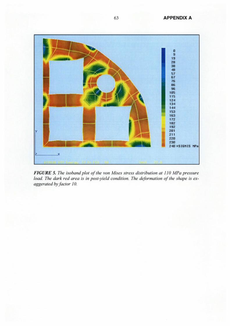
63 APPENDIX A
0 9
19 28 38 48 57 67 76 86 96
105 115 124 134 144 153 163 172 182 192 201 211 220 230 240 :SIGN IS NPa
FIGURE 5. The isoband plot of the von Mises stress distribution at 110 MP a pressure load. The dark red area is in post-yield condition. The deformation of the shape is exaggerated by factor 1 0.
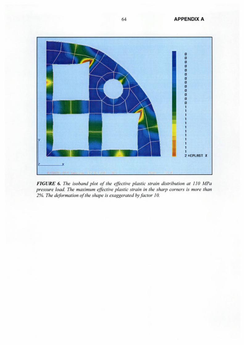
64
y
APPENDIX A
0 0 0 0 0 0 0 0 0 0 0 0 0 1 1 1 1 1 1 1 1 1 1 1 1 2 =EPLAST %
FIGURE 6. The isoband plot of the effective plastic strain distribution at 110 MP a pressure load. The maximum effective plastic strain in the sharp corners is more than 2%. The deformation of the shape is exaggerated by factor 10.

LIST OF REPORTS
POSIV A REPORTS 1999, situation 5/99
POSIVA 99-01
POSIV A 99-02
POSIV A 99-03
POSIVA 99-04
POSIV A 99-05
POSIVA 99-06
POSIV A 99-07
Measurement of thermal conductivity and diffusivity in situ: Literature survey and theoretical modelling of measurements Ilmo Kukkonen, Ilkka Suppala Geological Survey of Finland January 1999 ISBN 951-652-056-1
An overview of a possible approach to calculate rock movements due to earthquakes at Finnish nuclear waste repository sites Paul R. LaPointe, Trenton T. Cladouhos Golder Associates Inc., Washington, USA February 1999 ISBN 951-652-057-X
Site Scale Groundwater Flow in Olkiluoto Jari wfman VTTEnergy March 1999 ISBN 951-652-058-8
The psychosocial consequences of spent fuel disposal Jura Paavola, Liisa Eriinen University of Helsinki Department of Social Psychology March 1999 (in Finnish) ISBN 951-652-059-6
The effects of the final disposal facility for spent nuclear fuel on regional economy Seppo Laakso Seppo Laakso Urban Research March 1999 (in Finnish) ISBN 951-652-060-X
Radwaste management as a social issue Ismo Kantola University of Turku Department of Sociology March 1999 (in Finnish) ISBN 951-652-061-8
Safety assessment of spent fuel disposal in Hastholmen, Kivetty, Olkiluoto and Romuvaara- TILA-99 Timo Vieno, Henrik Nordman VTTEnergy March 1999 ISBN 951-652-062-6
1 (4)

POSIV A 99-08
POSIV A 99-09
POSIV A 99-10
LIST OF REPORTS 2 (4)
Final disposal of spent nuclear fuel in Finnish bedrock - Hastholmen site report P ekka Anttila, Fortum Engineering Oy Henry Ahokas, Fintact Oy Kai Front, VTT Communities and Infrastructure Heikki Hinkkanen, Posiva Oy Erik Johansson, Saanio & Riekkola Oy Seppo Paulamiiki, Geological Survey of Finland Reijo Riekkola, Saanio & Riekkola Oy J ouni Saari, Fortum Engineering Oy Pauli Saksa, Fintact Oy Margit Snellman, Posiva Oy Liisa Wikstrom, Posiva Oy Antti Ohberg, Saanio & Riekkola Oy March 1999 (to be published) ISBN 951-652-063-4
Final disposal of spent nuclear fuel in Finnish bedrock- Kivetty site report Pekka Anttila, Fortum Engineering Oy Henry Ahokas, Fintact Oy Kai Front, VTT Communities and Infrastructure Eero Heikkinen, Fintact Oy Heikki Hinkkanen, Posiva Oy Erik Johansson, Saanio & Riekkola Oy Seppo Paulamiiki, Geological Survey of Finland Reijo Riekkola, Saanio & Riekkola Oy Jouni Saari, Fortum Engineering Oy Pauli Saksa, Fintact Oy Margit Snellman, Posiva Oy Liisa Wikstrom, Posiva Oy Antti Ohberg, Saanio & Riekkola Oy March 1999 (to be published) ISBN 951-652-064-2
Final disposal of spent nuclear fuel in Finnish bedrock - Olkiluoto site report Pekka Anttila, Fortum Engineering Oy Henry Ahokas, Fintact Oy Kai Front, VTT Communities and Infrastructure Heikki Hinkkanen, Posiva Oy Erik Johansson, Saanio & Riekkola Oy Seppo Paulamiiki, Geological Survey of Finland Reijo Riekkola, Saanio & Riekkola Oy Jouni Saari, Fortum Engineering Oy Pauli Saksa, Fintact Oy Margit Snellman, Posiva Oy Liisa Wikstrom, Posiva Oy Antti Ohberg, Saanio & Riekkola Oy March 1999 (to be published) ISBN 951-652-065-0

POSIV A 99-11
POSIVA 99-12
POSIV A 99-13
POSIV A 99-14
POSIVA 99-15
POSIVA 99-16
LIST OF REPORTS 3 (4)
Final disposal of spent nuclear fuel in Finnish bedrock - Romuvaara site report Pekka Anttila, Fortum Engineering Oy Henry Ahokas, Fintact Oy Kai Front, VTT Communities and Infrastructure Heikki Hinkkanen, Posiva Oy Erik Johansson, Saanio & Riekkola Oy Seppo Paulamiiki, Geological Survey of Finland Reijo Riekkola, Saanio & Riekkola Oy J ouni Saari, Fortum Engineering Oy Pauli Saksa, Fin tact Oy Margit Snellman, Posiva Oy Liisa Wikstrom, Posiva Oy Antti Ohberg, Saanio & Riekkola Oy March 1999 (to be published) ISBN 951-652-066-9
Site scale groundwater flow in Hastholmen Jari LOfman VTTEnergy March 1999 (to be published) ISBN 951-652-067-7
Regional-to-site scale groundwater flow in Kivetty Eero Kattilakoski VTTEnergy Ferenc Meszaros The Relief Laboratory, Harskut, Hungary April1999 ISBN 951-652-068-5
Regional-to-site scale groundwater flow in Romuvaara Eero Kattilakoski, Lasse Koskinen VTTEnergy April1999 ISBN 951-652-069-3
Site-to-canister scale flow and transport at the Hastholmen, Kivetty, Olkiluoto and Romuvaara sites Antti Poteri, Mikko Laitinen VTTEnergy March 1999 (to be published) ISBN 951-652-070-7
Assessment of radiation doses due to normal operation, incidents and accidents of the final disposal facility Jukka Rossi, Heikki Raiko, Vesa Suolanen, Mikko Ilvonen VTTEnergy March 1999 (in Finnish) ISBN 951-652-071-5

POSIV A 99-17
POSIV A 99-18
POSIV A 99-19
POSIV A 99-20
POSIVA 99-21
POSIV A 99-22
LIST OF REPORTS
Assessment of health risks brought about by transportation of spent fuel Vesa Suolanen, Risto Lautkaski, Jukka Rossi VTTEnergy March 1999 (in Finnish) ISBN 951-652-072-3
Design report of the disposal canister for twelve fuel assemblies Heikki Raiko VTTEnergy Jukka-Pekka Salo Posiva Oy May 1999 ISBN 951-652-073-1
Estimation of block conductivities from hydrologically calibrated fracture networks - description of methodology and application to Romuvaara investigation area Auli Niemi1,2, Kimmo Kontio2
,
Auli Kuusela-Lahtinen2, Tiina Vaittinen2
4 (4)
1Royal Institute of Technology, Hydraulic Engineering, Stockholm 2VTT Communities and Infrastructure March 1999 ISBN 951-652-074-X
Porewater chemistry in compacted bentonite Arto Muurinen, Jarmo Lehikoinen VTT Chemical Technology March 1999 ISBN 951-652-075-8
Ion diffusion in compacted bentonite Jarmo Lehikoinen VTT Chemical Technology March 1999 ISBN 951-652-076-6
Use of the 14C-PMMA and He-gas methods to characterise excavation disturbance in crystalline rock forma Autio, Timo Kirkkomiiki Saanio & Riekkola Oy Marja Siitari-Kauppi University of Helsinki Laboratory of Radiochemistry Jussi Timonen, Mika Laajalahti, Tapani Aaltonen, ]ani Maaranen University of JyvaskyHi Department of Physics April1999 ISBN 951-652-077-4