Embed Size (px)
Citation preview

UCL Estates
Page 1 of 33 UCL Estates Design Requirements for Connections to the UCL District Heating Network
Version V.1
Date 06/07/2017
Uncontrolled when printed
Design Requirements for Connections to the UCL District Heating Network

UCL Estates
Page 2 of 33 UCL Estates Design Requirements for Connections to the UCL District Heating Network
Version V.1
Date 06/07/2017
Uncontrolled when printed
Contents
1 Glossary ............................................................................................................................................... 3
2 Who is this guide for? ......................................................................................................................... 4
3 Scope of this guide ............................................................................................................................. 5
4 Introduction .......................................................................................................................................... 6
5 Design approval process ................................................................................................................. 10
6 Project responsibilities ..................................................................................................................... 14
7 Heat substation room design .......................................................................................................... 17
8 Secondary heating system design ................................................................................................. 20
9 Appendix: Typical required secondary heat system schematic ................................................. 32

UCL Estates
Page 3 of 33 UCL Estates Design Requirements for Connections to the UCL District Heating Network
Version V.1
Date 06/07/2017
Uncontrolled when printed
1 Glossary
Term Definition
AHU Air handling unit
BMS Building management system
CHP Combined heat and power (refers to engine for low-carbon heat generation)
CIBSE Chartered Institution of Building Services Engineers
CT Constant temperature
Delta T Temperature differential
DEN District energy network
DHW Domestic hot water
DHWS Domestic hot water service
dP Differential pressure
EM&I Engineering, Maintenance and Infrastructure (relating to team within UCL’s Estates department)
MEP Mechanical, electrical and plumbing
MID Measuring Instruments Directive (European directive 2004/22/EC)
PEX Plate heat exchanger
PPE Personal protective equipment
RIBA Royal Institute of British Architects
TRV Thermostatic radiator valve
VRF Variable refrigerant flow
VSD Variable speed drive
VT Variable temperature
Disclaimer
This guidance is for information only, UCL accepts no liability for any loss, damage or
inconvenience caused as a result of reliance on this information.
Before signing agreements for any design work, appropriate legal and engineering professionals
should be consulted.

UCL Estates
Page 4 of 33 UCL Estates Design Requirements for Connections to the UCL District Heating Network
Version V.1
Date 06/07/2017
Uncontrolled when printed
2 Who is this guide for?
The following guidance should be provided to all parties relevant in connecting buildings to
UCL’s Bloomsbury campus district heating network. This may include, but is not limited to:
“The UPO/ EPM”
Building developers and the wider client-side project stakeholders, project
teams/sponsors etc. who are developing buildings on the Bloomsbury campus, i.e.
UCL Capital and SMP Project Management teams and their consultants,
“The Building Operator”
Building operators who manage buildings’ heating systems, generally UCL Estates
but not exclusively,
“The Designer”
Any M&E or other engineers designing buildings for connection to the district heating
network,
“The District Heating Operator”
UCL Estates – Facilities and Infrastructure, represented by the Head of Engineering,
Maintenance and Infrastructure (EM&I) and the “CHP Team”.
UCL Estates
Page 5 of 33 UCL Estates Design Requirements for Connections to the UCL District Heating Network
Version V.1
Date 06/07/2017
Uncontrolled when printed
3 Scope of this guide
This document provides guidance for connection of new, existing (see definition below) and
refurbished buildings to the district heating network, as well as disconnections and network
diversions. These are defined as:
Any building proposed for construction on the Bloomsbury campus that is to be
connected to the district heating network,
Any existing building to be added to the district heating network,
Any works that require the existing network to be diverted or modified,
Any existing building being refurbished where there is an opportunity to rearrange the
building’s mechanical heating systems,
Any building being extended or where significant alterations or additions are being made
to the building’s mechanical services (e.g. consequential improvements).
It is not possible in this document to go into the details of all types and permutations of heating
systems within existing buildings, which either are connected or could be connected, to the
district heating network. However, the principles set out herein should be used by the Designer
when refurbishing existing buildings or connecting existing building to the district heating
network. Where a wider refurbishment is not envisaged, it is essential that connection of existing
buildings to the district heating network are subject to a feasibility study to achieve the standards
for connection identified herein.
Projects wishing to connect to UCL’s high voltage network should refer to the standards
contained within UCL’s “Design Guide for Mechanical, Electrical and Public Health Services”.
UCL Estates
Page 6 of 33 UCL Estates Design Requirements for Connections to the UCL District Heating Network
Version V.1
Date 06/07/2017
Uncontrolled when printed
4 Introduction
4.1 Context
UCL has a comprehensive district heating network serving buildings on its main Bloomsbury
campus, which is part of its aim to improve energy efficiency and reduce carbon emissions. UCL
is determined to reduce its carbon footprint through good standards of design of its buildings and
services.
The purpose of this guide is to set a standard in assisting the Designer in implementing the
connection of buildings and/or heating systems to the district heating network. These standards
are applicable to a variety of building types found on the main campus and elsewhere, and
consideration is made for new developments and major refurbishments.
The standards are intended to ensure that any new or altered connections are fully considered
and authorised by UCL, so that the network can be operated in the most efficient manner. The
aim is to help the UPO/ EPM and the Designer to understand the system and provide secondary
heating networks that achieve UCL’s ambitions for cost and carbon emission reductions. If these
standards are not adhered to permission to take heat from the network will be withheld.
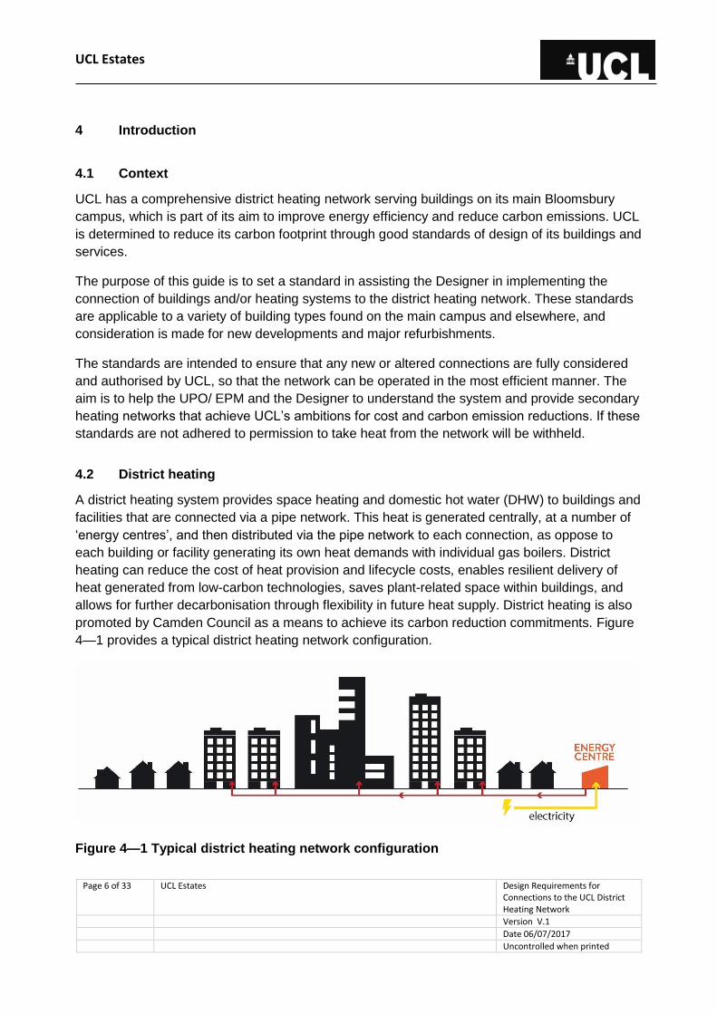
4.2 District heating
A district heating system provides space heating and domestic hot water (DHW) to buildings and
facilities that are connected via a pipe network. This heat is generated centrally, at a number of
‘energy centres’, and then distributed via the pipe network to each connection, as oppose to
each building or facility generating its own heat demands with individual gas boilers. District
heating can reduce the cost of heat provision and lifecycle costs, enables resilient delivery of
heat generated from low-carbon technologies, saves plant-related space within buildings, and
allows for further decarbonisation through flexibility in future heat supply. District heating is also
promoted by Camden Council as a means to achieve its carbon reduction commitments. Figure
4—1 provides a typical district heating network configuration.
Figure 4—1 Typical district heating network configuration
UCL Estates
Page 7 of 33 UCL Estates Design Requirements for Connections to the UCL District Heating Network
Version V.1
Date 06/07/2017
Uncontrolled when printed
UCL supplies space heating and DHW to connected buildings on its Bloomsbury campus via a
primary hot water network, fed from four energy centres (as well as a number of contaminated
gas-fired boilers, e.g. stand-alone boilers at BSUs). The system uses 2no. combined heat and
power (CHP) engines as a low-carbon heat source. CHP engines generate heat and power
simultaneously, providing carbon savings through off-setting the use of grid electricity. Heat from
the engines is supplemented directly by gas and oil boilers, as well as indirectly by steam.
A district heating network has specific operational criteria that must be achieved, in order to
deliver reliable and efficiently-generated heat to connected buildings on the campus. One
example is achieving a large temperature differential, which is a function of how the buildings
interact with the network.
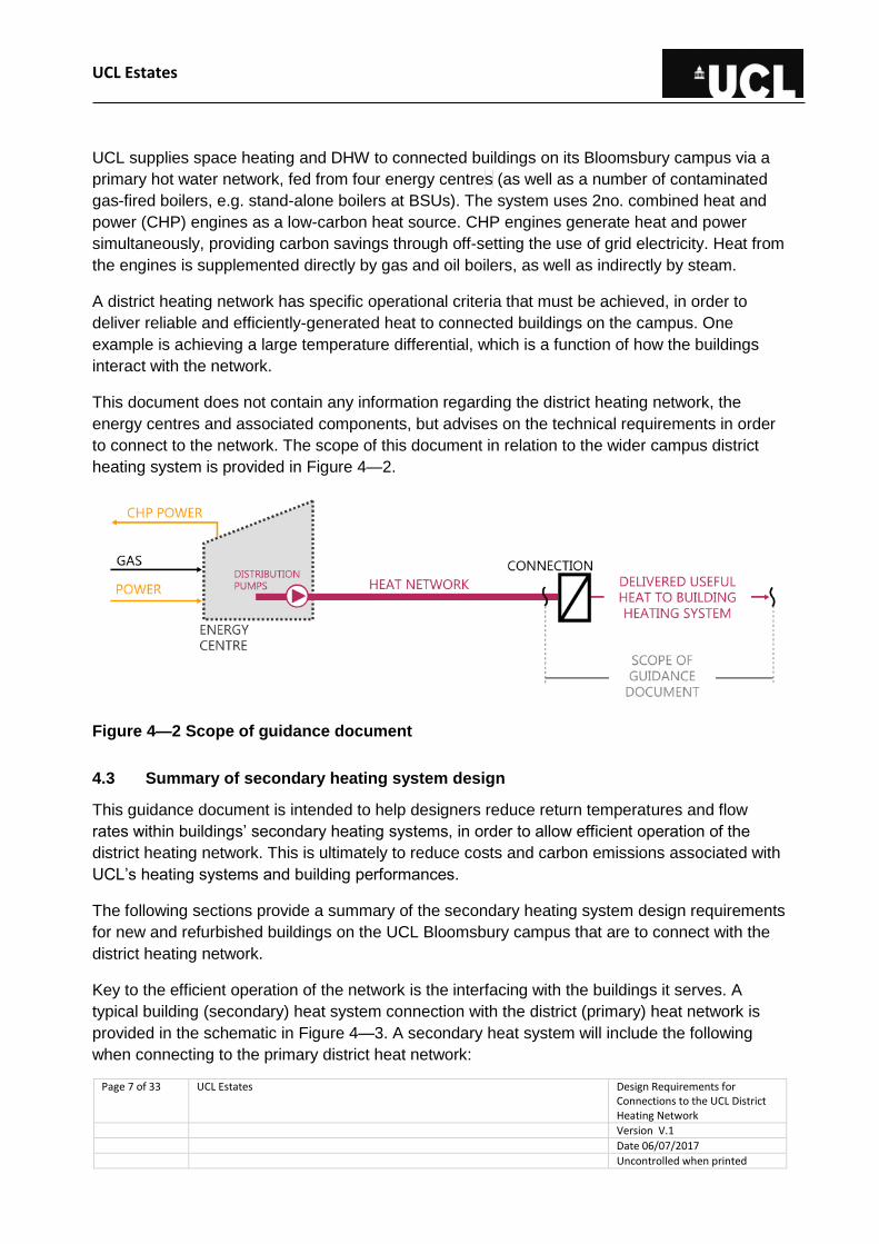
This document does not contain any information regarding the district heating network, the
energy centres and associated components, but advises on the technical requirements in order
to connect to the network. The scope of this document in relation to the wider campus district
heating system is provided in Figure 4—2.
Figure 4—2 Scope of guidance document
4.3 Summary of secondary heating system design
This guidance document is intended to help designers reduce return temperatures and flow
rates within buildings’ secondary heating systems, in order to allow efficient operation of the
district heating network. This is ultimately to reduce costs and carbon emissions associated with
UCL’s heating systems and building performances.
The following sections provide a summary of the secondary heating system design requirements
for new and refurbished buildings on the UCL Bloomsbury campus that are to connect with the
district heating network.
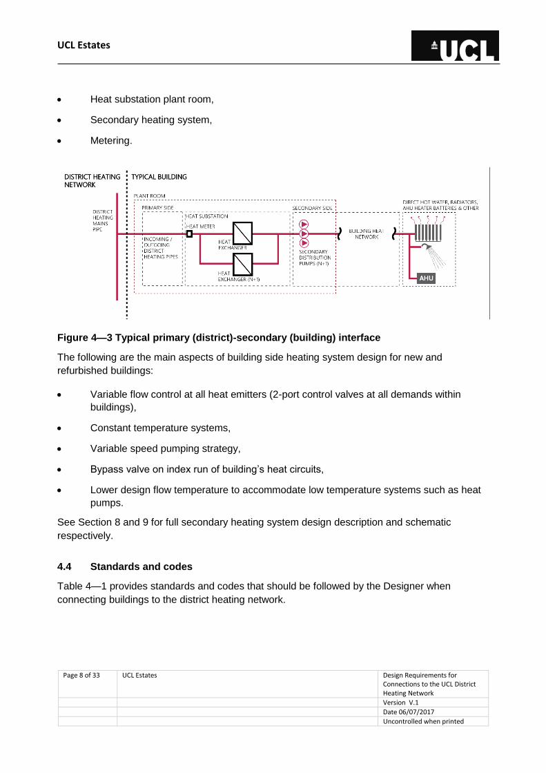
Key to the efficient operation of the network is the interfacing with the buildings it serves. A
typical building (secondary) heat system connection with the district (primary) heat network is
provided in the schematic in Figure 4—3. A secondary heat system will include the following
when connecting to the primary district heat network:
UCL Estates
Page 8 of 33 UCL Estates Design Requirements for Connections to the UCL District Heating Network
Version V.1
Date 06/07/2017
Uncontrolled when printed
Heat substation plant room,
Secondary heating system,
Metering.
Figure 4—3 Typical primary (district)-secondary (building) interface
The following are the main aspects of building side heating system design for new and
refurbished buildings:
Variable flow control at all heat emitters (2-port control valves at all demands within
buildings),
Constant temperature systems,
Variable speed pumping strategy,
Bypass valve on index run of building’s heat circuits,
Lower design flow temperature to accommodate low temperature systems such as heat
pumps.
See Section 8 and 9 for full secondary heating system design description and schematic
respectively.
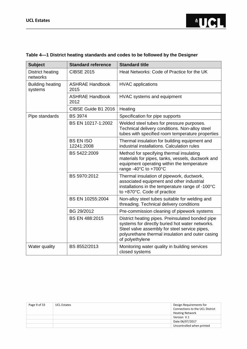
4.4 Standards and codes
Table 4—1 provides standards and codes that should be followed by the Designer when
connecting buildings to the district heating network.
UCL Estates
Page 9 of 33 UCL Estates Design Requirements for Connections to the UCL District Heating Network
Version V.1
Date 06/07/2017
Uncontrolled when printed
Table 4—1 District heating standards and codes to be followed by the Designer
Subject Standard reference Standard title
District heating networks
CIBSE 2015 Heat Networks: Code of Practice for the UK
Building heating systems
ASHRAE Handbook 2015
HVAC applications
ASHRAE Handbook 2012
HVAC systems and equipment
CIBSE Guide B1 2016 Heating
Pipe standards BS 3974 Specification for pipe supports
BS EN 10217-1:2002 Welded steel tubes for pressure purposes. Technical delivery conditions. Non-alloy steel tubes with specified room temperature properties
BS EN ISO 12241:2008
Thermal insulation for building equipment and industrial installations. Calculation rules
BS 5422:2009 Method for specifying thermal insulating materials for pipes, tanks, vessels, ductwork and equipment operating within the temperature range -40°C to +700°C
BS 5970:2012 Thermal insulation of pipework, ductwork, associated equipment and other industrial installations in the temperature range of -100°C to +870°C. Code of practice
BS EN 10255:2004 Non-alloy steel tubes suitable for welding and threading. Technical delivery conditions
BG 29/2012 Pre-commission cleaning of pipework systems
BS EN 488:2015 District heating pipes. Preinsulated bonded pipe systems for directly buried hot water networks. Steel valve assembly for steel service pipes, polyurethane thermal insulation and outer casing of polyethylene
Water quality BS 8552/2013 Monitoring water quality in building services closed systems

UCL Estates
Page 10 of 33 UCL Estates Design Requirements for Connections to the UCL District Heating Network
Version V.1
Date 06/07/2017
Uncontrolled when printed
5 Design approval process
The UPO/ EPM and the Designer will comply with this document and follow the approval and
acceptance process. Key stages and the UPO/ EPM’s responsibilities are demonstrated in
Figure 5—1 in line with the recommended RIBA 2013 plan of work and UCL’s Stage Gate
process. Additional information is provided in the sections below on aspects of the design
approval process specific to UCL’s district heating network (bold and italic). The District
Heating Operator can request to review the design, inspect the installation and if deemed
necessary ask for changes to be made, in order for the installation/design to comply with the
standards, as detailed in this document.
Figure 5—1 Key project stages
•Notification of interest and permission request to connect
•Agreement with the District Heating Operator and the DEN Work Group
•Issue of design document
Stage 1
Agreement to connect
•Workshop between the District Heating Operator, the DEN Working Group and the Designer
•Introduction of connection protection and technical requirements
•Load assessment development, review and sign-off
Stage 2
Design Guidance issued to MEP team workshop
•The design shall be submitted to the District Heating Operator and the DEN Working Group for review and approval
•The District Heating Operator to confirm that services and equipment meet requirements of this specification
Stage 3
Concept design review
Sign-off by network operator
•Services and equipment shall be inspected by the Building Developer, District Heating Operator and the DEN Working Group
•Both parties shall sign off acceptance that the requirements of this document are met
Stage 4
Detailed design review and sign-off
Timing approval
•Witness testing and proof of performance
Stage 5
Construction and use
UCL Estates
Page 11 of 33 UCL Estates Design Requirements for Connections to the UCL District Heating Network
Version V.1
Date 06/07/2017
Uncontrolled when printed
5.1 Notification of interest and permission request to connect
Connection to the district heating network is prioritised over installation of a standalone heating
system. Serving heat demands from a district heating network provides cost and carbon
reduction benefits, which aids in achieving UCL’s ambitions for more sustainable operation of its
estates.
Any works taking place which may impact the campus either directly or indirectly should be
brought to the attention of the Head of Engineering, Maintenance and Infrastructure as early as
possible and definitely before Stage 2 is complete (see Figure 5—1). This will ensure that
consideration of how the works may affect the wider system can be given and mitigation
measures if required can be investigated. It will also allow an impact assessment to be made to
ensure other consumers are not adversely affected by any works elsewhere on the system.
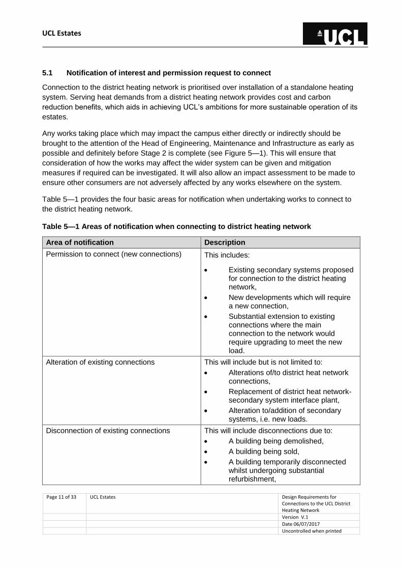
Table 5—1 provides the four basic areas for notification when undertaking works to connect to
the district heating network.
Table 5—1 Areas of notification when connecting to district heating network
Area of notification Description
Permission to connect (new connections) This includes:
Existing secondary systems proposed for connection to the district heating network,
New developments which will require a new connection,
Substantial extension to existing connections where the main connection to the network would require upgrading to meet the new load.
Alteration of existing connections This will include but is not limited to:
Alterations of/to district heat network connections,
Replacement of district heat network-secondary system interface plant,
Alteration to/addition of secondary systems, i.e. new loads.
Disconnection of existing connections This will include disconnections due to:
A building being demolished,
A building being sold,
A building temporarily disconnected whilst undergoing substantial refurbishment,
UCL Estates
Page 12 of 33 UCL Estates Design Requirements for Connections to the UCL District Heating Network
Version V.1
Date 06/07/2017
Uncontrolled when printed
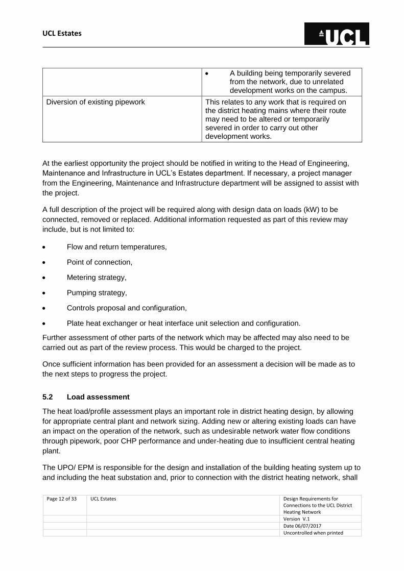
A building being temporarily severed from the network, due to unrelated development works on the campus.
Diversion of existing pipework This relates to any work that is required on the district heating mains where their route may need to be altered or temporarily severed in order to carry out other development works.
At the earliest opportunity the project should be notified in writing to the Head of Engineering,
Maintenance and Infrastructure in UCL’s Estates department. If necessary, a project manager
from the Engineering, Maintenance and Infrastructure department will be assigned to assist with
the project.
A full description of the project will be required along with design data on loads (kW) to be
connected, removed or replaced. Additional information requested as part of this review may
include, but is not limited to:
Flow and return temperatures,
Point of connection,
Metering strategy,
Pumping strategy,
Controls proposal and configuration,
Plate heat exchanger or heat interface unit selection and configuration.
Further assessment of other parts of the network which may be affected may also need to be
carried out as part of the review process. This would be charged to the project.
Once sufficient information has been provided for an assessment a decision will be made as to
the next steps to progress the project.
5.2 Load assessment
The heat load/profile assessment plays an important role in district heating design, by allowing
for appropriate central plant and network sizing. Adding new or altering existing loads can have
an impact on the operation of the network, such as undesirable network water flow conditions
through pipework, poor CHP performance and under-heating due to insufficient central heating
plant.
The UPO/ EPM is responsible for the design and installation of the building heating system up to
and including the heat substation and, prior to connection with the district heating network, shall

UCL Estates
Page 13 of 33 UCL Estates Design Requirements for Connections to the UCL District Heating Network
Version V.1
Date 06/07/2017
Uncontrolled when printed
commission the Designer to conduct a heat load analysis, including a hydraulic simulation, to be
provided to the District Heating Operator and the DEN Working Group for sign-off.
The Designer shall refer to section 2.1 of the CIBSE Heat Network Code of Practice (2015) for
best practice guidance on estimating heat loads. Where the proposal is to connect a refurbished
building to the district heating network, advice should be sought from UCL’s Energy Manager to
help determine the load based on existing meter data.
The Designer shall provide the calculated heat loads to the District Heating Operator as per
Table 5—2. which will be reviewed and approved at the third stage of the project (see Figure 5—
1).
Overstating the required capacities must be avoided in order to maintain good control at low
demands, and to avoid unnecessary network and heat substation equipment costs.
Table 5—2 Heat loads to be provided to the District Heating Operator by the Designer for
approval
Heat load to provide Space heating DHW
Peak load excluding warm-up from cold (kW)
Peak load including warm-up from cold (kW)

UCL Estates
Page 14 of 33 UCL Estates Design Requirements for Connections to the UCL District Heating Network
Version V.1
Date 06/07/2017
Uncontrolled when printed
6 Project responsibilities
6.1 General principles of project responsibility
For clarity of responsibilities for projects connecting buildings to the district heating network, the
general principles are:
The project pays for the connection, which includes design, enabling works, civil works,
all mechanical, electrical and control works and any other elements which enable
connection to the network, including time spent by the District Heating Operator (CHP
Team) operatives / engineers to arrange and attend network shutdowns and other
necessary works,
District heating network design will be through consultants designated or approved by the
District Heating Operator,
The District Heating Operator will set the specification and type of equipment to be
installed on the district heating side,
Installation of district heating equipment and pipework may fall to the Building District
Heating Operator to implement or may be carried out by the project contractors subject to
permissions,
No system is to be made live without sign-off from the District Heating Operator (Figure
5—1),
No system will be connected or services provided until the controls and monitoring are in
place to ensure the services can be managed effectively.
Where any third party connections are to be made a heat supply agreement (including details on
agreed pricing) must be in place prior to construction.
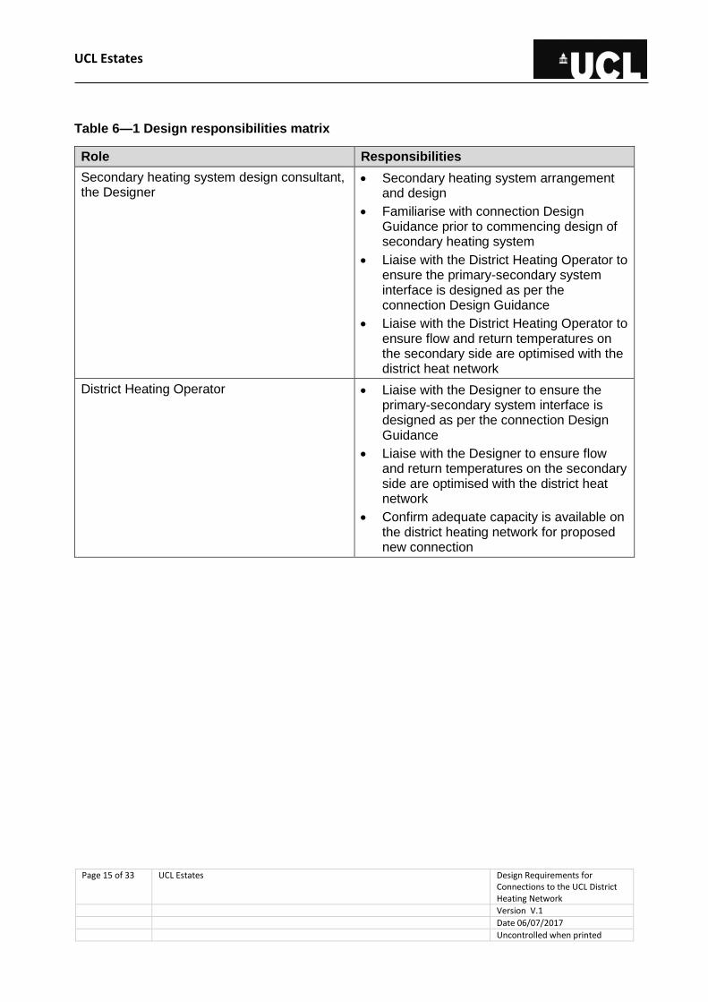
6.2 Design responsibilities
Table 6—1 provides the design responsibilities that include, but are not limited to, the various
parties that may be involved in connecting buildings to the district heating network.
Further detail on the responsibilities of each party for designing, building, operation,
maintenance, repair and plant replacement is provided in Figure 6—1.
UCL Estates
Page 15 of 33 UCL Estates Design Requirements for Connections to the UCL District Heating Network
Version V.1
Date 06/07/2017
Uncontrolled when printed
Table 6—1 Design responsibilities matrix
Role Responsibilities
Secondary heating system design consultant, the Designer
Secondary heating system arrangement and design
Familiarise with connection Design Guidance prior to commencing design of secondary heating system
Liaise with the District Heating Operator to ensure the primary-secondary system interface is designed as per the connection Design Guidance
Liaise with the District Heating Operator to ensure flow and return temperatures on the secondary side are optimised with the district heat network
District Heating Operator Liaise with the Designer to ensure the primary-secondary system interface is designed as per the connection Design Guidance
Liaise with the Designer to ensure flow and return temperatures on the secondary side are optimised with the district heat network
Confirm adequate capacity is available on the district heating network for proposed new connection
UCL Estates
Page 16 of 33 UCL Estates Design Requirements for Connections to the UCL District Heating Network
Version V.1
Date 06/07/2017
Uncontrolled when printed
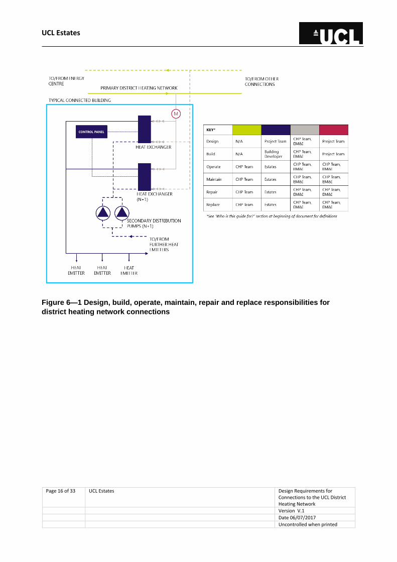
Figure 6—1 Design, build, operate, maintain, repair and replace responsibilities for
district heating network connections
UCL Estates
Page 17 of 33 UCL Estates Design Requirements for Connections to the UCL District Heating Network
Version V.1
Date 06/07/2017
Uncontrolled when printed
7 Heat substation room design
The substation acts as an interface between the district (primary) heating network and building
(secondary) heating systems to serve the needs of the connected buildings, allowing the pre-
defined operating conditions to be met. It ensures that the higher operating temperatures of the
district heat network are not being routed directly to the buildings.
The UPO/ EPM is responsible for providing adequate space within the building’s plant room for a
heat substation, i.e. the interface between the district heat network and secondary system. This
should be located on the ground floor or at a step-free basement level. It should be easy and
safe to access the plant room for maintenance, operation and equipment replacement purposes.
Access to the plant room shall be permanent. It must also be possible for the district heating
network to be accessed within the plant room (e.g. for metering and isolation purposes).
The substation room consists of incoming district heating pipework and the secondary heating
system equipment, interfaced at the plate heat exchangers. The Designer shall consider in their
design the following items:
Plate heat exchangers,
Substation plant room,
Secondary heating system equipment,
Easily maintained plant room,
A suitable and sufficient plant replacement strategy,
Ensuring Principal Designer duties are carried out as per CDM Regulations 2015.
The following sections consider the plate heat exchanger and substation plant room design.
Guidance for BMS, metering and other secondary heating system equipment design is provided
in section 8.
7.1 Heat exchanger design
All plate heat exchangers shall be duplex in an N+1 configuration, i.e. an additional heat
exchanger for resiliency. Each heat exchanger shall be sized to carry 100% of the heat load, but
under normal conditions shall run at 50% capacity. In the event that one heat exchanger fails,
the other shall run at full capacity to ensure adequate heat is delivered to the building.
If two separate building heating systems are to be served from a single plant room, the
redundant heat exchanger can be used for resiliency for both systems.
Where an N+1 configuration is not feasible (e.g. in a refurbished building with restricted plant
room space) a spare plate heat exchanger unit shall be kept onsite in case of a failure. This

UCL Estates
Page 18 of 33 UCL Estates Design Requirements for Connections to the UCL District Heating Network
Version V.1
Date 06/07/2017
Uncontrolled when printed
should not be the preferred option for heat exchanger design and it must be demonstrated by
the Designer why the preferred N+1 configuration is not feasible.
Strainers shall be used to protect the plate heat exchangers, and flushing loops installed on the
secondary side to bypass the heat exchanger. Heat exchangers have relatively small clearances
and can become partially or fully blocked by debris, which is true particularly with new buildings
that are connected without adequate flushing systems. Use of strainers will marginally increase
pumping energy requirements; this should be accounted for by the Designer. Preference for
DHW generation is via use of plate heat exchangers connected to the district heating network.
Where storage is required, this should be provided using buffer vessels, i.e. calorifiers with coils
shall not be used.
All plate heat exchangers shall include insulation jackets which are fully removable for
maintenance purposes.
7.2 Plant room design
The Designer shall design the plant room to ensure adequate space is provided for the district
heating-building system interconnection. The following minimum space requirement guidance
shall be adhered to:
Buildings with peak heating loads < 2,000kW – 5m x 6m = 30m2,
Buildings with peak heating loads > 2,000kW – 7.5m x 7.5m = 56m2.
In addition to plant heating equipment, adequate space shall be provided for the plant room
components listed in Table 7—1.
Table 7—1 Non-heating equipment components of plant room
Category Component
Electrical requirements Electrical supply for control panel
Small power electrical sockets, 240V, IP55 rated
Lighting
Signals from secondary heating system
Maintenance and replacement
Area for maintenance of plant equipment
Space and route for removal and replacement of plant equipment
Water requirements Water supply to feed secondary heating system
Water drainage
Ventilation Ventilation system for plant room
Health and safety Visible floor plan with accompanying schematic
Visitor sign-in and sign-out book
Anti-slip floor finish
Noise and vibration attenuation

UCL Estates
Page 19 of 33 UCL Estates Design Requirements for Connections to the UCL District Heating Network
Version V.1
Date 06/07/2017
Uncontrolled when printed
Category Component
Fire detection, suppression and means of escape
PPE requirements
Fire stopping in all walls and floor perforations
All UCL Health and Safety standards to be followed
Building Water tight/penetration sealed
Concrete stands for heating equipment
Equipment protection
Trench/pit covers
Lockable doors (UCL electronic access control)
Minimum door dimension requirement:
- 1.5m W x 2.5m H for 30m2 plant room
- 2.0m W x 2.5m H for 56m2 plant room
Pipework labelling All district heating pipework through each wall penetration and/or duct of plant room should identify:
- Size of pipework
- Type of service and temperatures
- Area of building served (including via, where applicable)
- Area of building returning from
UCL Estates
Page 20 of 33 UCL Estates Design Requirements for Connections to the UCL District Heating Network
Version V.1
Date 06/07/2017
Uncontrolled when printed
8 Secondary heating system design
This section sets out the specific requirements – design, conditions, noise and vibration, heat
losses, materials, and water quality – for secondary (building) heating systems, to allow a
building to receive heat from the primary district heating network in an efficient manner.
The secondary heating system refers to the network and associated services between the
secondary side of the heat exchanger, located in the substation plant room, and each
connection point for space heating or DHW purposes. This includes the associated mechanical
components such as pumps, speed controllers, pipes, pressurisation units, control panels and
electrical supplies. Plate heat exchanger and plant room design guidance is provided in section
7.
Failure to comply with the following secondary system design requirements will be detrimental to
the efficient operation of UCL’s district heating network, hindering potential cost and carbon
reductions from its use, and could result in the building connection being refused. It is essential
that the Designer adheres to the following guidelines for any building proposed for connection to
the district heating network.
8.1 General requirements
As discussed in the following sections, the secondary heat system should be designed in order
to:
Be compatible with the primary district heating network,
Be reliable, efficient and easily accessible for maintenance,
Minimise operating costs and optimise carbon savings,
Accommodate the variations in demand-side and environmental conditions (load and
temperature),
Minimise heat losses, avoiding wasted heat and overheating during summer,
Lower the operating temperature of the district heating network.
Each secondary system will be indirectly connected to the district heating network via a plate
heat exchanger, which hydraulically separates the two systems (see section 7).
8.2 Specific design requirements
The key design principle of the district heating network is that it operates with a large
temperature differential (delta T). A large delta T:
Increases the network’s capacity for carrying heat,
UCL Estates
Page 21 of 33 UCL Estates Design Requirements for Connections to the UCL District Heating Network
Version V.1
Date 06/07/2017
Uncontrolled when printed
Reduces required sizes of pipes,
Reduces pump power requirements,
Maximises operation of the CHP plant.
UCL Estates
Page 22 of 33 UCL Estates Design Requirements for Connections to the UCL District Heating Network
Version V.1
Date 06/07/2017
Uncontrolled when printed
8.2.1 Flow control strategy
The flow control strategy for secondary heat systems will be to utilise variable flow-constant
temperature (CT) circuits, as shown in Figure 8—1.
Variable temperature (VT) circuits shall only be permitted for radiator circuits, to reduce
temperatures under low load or high external ambient temperatures. The temperature variation
shall be achieved by a 3-port mixing valve between the flow and return. This arrangement
requires separate pumping for VT and CT circuits. Designers shall ensure the pump control
principles described below are applied in each case. Radiators shall be equipped with 2-port
control via TRV. For radiator circuits multi-zone control via the building management system
(BMS) is preferred.
The BMS for each individual terminal load within buildings shall control the secondary system
motorised valves. This regulates the flow of heating water to the heat emitters at the loads based
on demand.
The secondary system pump shall be variable speed drive (VSD) in order to maintain the
required differential pressure (dP) set point as the regulation valves open and close to meet
demands. A dP sensor at the index run of the secondary system shall control the VSD pump to
maintain this pressure difference. In the case of extreme low building heat load (e.g. out of term-
time in summer) when all regulation valves are shut, an automatic 2-port bypass valve, located
on the index run of the secondary circuit, will divert secondary heating water to the return. This
ensures minimum flow through the pump is achieved as a safety measure, i.e. to avoid damage
caused by operating at low flow. Should this extreme low heat demand persist for a period of
time (to be agreed with UCL on a project-specific basis) the BMS shall be programmed to switch
of the pumps until the heat demand increases (using a logic to be agreed with UCL on a project-
specific basis).
The automatic bypass valve on the index run is closed under normal operation. Utilisation of the
bypass arrangement shall be kept to an absolute minimum as this decreases delta T.
VSD pumping with 2-port control at heat emitters reduces pumping energy consumption as the
pump reacts to fluctuations in demand, i.e. it only pumps the volume of water necessary to meet
demand.
It must be noted that under no circumstance should 3-port control valves be installed at heat
emitters with a VSD flow control strategy in place. This will return high temperatures to the plate
heat exchanger, reducing delta T on the district heating network and ultimately reducing its
overall efficiency.
The flow of district heating network water circulating through the plate heat exchanger within the
heat substation is regulated by a motorised valve, which is controlled by a temperature sensor
on the secondary flow side, i.e. if secondary flow temperature drops the valve is opened to allow
more primary flow through the heat exchanger. The measures described herein should help to
UCL Estates
Page 23 of 33 UCL Estates Design Requirements for Connections to the UCL District Heating Network
Version V.1
Date 06/07/2017
Uncontrolled when printed
reduce return temperature on the district side (see Section 8.2.2 for details). As a further
precaution, return temperature limiting should be employed at each substation.
The flow control strategy described above provides pumping energy savings over other
arrangements due to the VSD pumps which can match building demand.
The secondary heating system shall be designed as a single circuit (note comments above on
use of VT circuits). Using a single circuit reduces return water temperatures to the plate heat
exchangers as the water passes through the full heating system, maximising the opportunities to
lose heat. A single circuit also reduces complexity and costs of the system as fewer pumps are
required.
The secondary system shall not use low loss headers. Use of low loss headers diverts a
significant portion of the flow in the primary circuit from the terminal units, meaning it is not
cooled. This approach is often used with boiler systems but is not compatible with district heating
connections, where the temperature differential is a key factor in efficient operation of the district
heat network (see section 8.2).

UCL Estates
Page 24 of 33 UCL Estates Design Requirements for Connections to the UCL District Heating Network
Version V.1
Date 06/07/2017
Uncontrolled when printed
Figure 8—1 Secondary heating system and connection with district heating network
8.2.2 Flow and return temperatures
The CIBSE Heat Network Code of Practice (2015) states that approach temperatures for heat
exchangers at primary-secondary plate heat exchanger interfaces should not exceed 3°C

UCL Estates
Page 25 of 33 UCL Estates Design Requirements for Connections to the UCL District Heating Network
Version V.1
Date 06/07/2017
Uncontrolled when printed
(Figure 8—2). The Designer must check whether sufficient heat transfer occurs at low loads and
flow rates with the chosen heat exchanger and these approach temperatures. Consultation with
the heat exchanger supplier is recommended.
The Designer should liaise with the District Heating Operator to confirm flow and return
temperatures available from the district heat network, in order to achieve these approach
temperatures and to optimise the building’s connection with the network.
Guidance on flow and return temperatures for the district heating network and secondary
systems is provided in Table 8—1. These temperatures are indicative of typical buildings –
actual design temperatures must be confirmed through liaison between the Designer and the
District Heating Operator (see section 5).
It may be the case that the district heating network’s operating temperatures are reduced during
summer months to reduce standing pipe heat losses. The Designer must liaise with the District
Heating Operator to confirm this operating strategy, and shall incorporate this into their design.
The secondary heating system flow temperature shall be designed to avoid the risks of
Legionella occurring in the hot water systems, and accounts for heat losses within the secondary
system.

UCL Estates
Page 26 of 33 UCL Estates Design Requirements for Connections to the UCL District Heating Network
Version V.1
Date 06/07/2017
Uncontrolled when printed
Figure 8—2 Approach temperatures for building connections to the district heating
network
It should be noted that a long-term ambition (over the next 15 years) for UCL is to reduce district
heating network operating temperatures, in order to reduce operating costs associated with
heating equipment and standing network losses. It is the responsibility of the UPO/ EPM to
confirm the district heating operating temperatures for the building being proposed for
connection, at the planned time of connection. These temperatures should be incorporated into
the secondary heat system design.
Table 8—1 Indicative district heating and secondary system operating temperatures
Building for connection
Season District heating network Secondary heating
system
- - Tflow Treturn Tflow Treturn
New Winter 95 65 70 40
Summer 70 40 60 30
Refurbished Winter 95 65 80 60
Summer 70 40 70 50
8.2.3 Pumping strategy
Secondary pumps shall be VSD to match supply with demand and save pumping power. As
shown Figure 8—3 the secondary pumps shall be installed on the return leg, just before the
primary-secondary heat exchanger interface, to avoid cavitation issues within heat exchangers.
Pumps shall be installed in parallel to accommodate any buildings with a wide variety in loading,
i.e. a staged pumping strategy to reduce power consumption by reducing pump modulation. By
employing multiple pumps in parallel, the system will be able to meet the required return
temperature at all times.
Pumps connected to the district heating network where a run and standby unit is required must
not be twin head units and must be piped and connected independently. This avoids interrupting
service during maintenance or replacement.
The number of pumps selected is a function of the maximum and minimum flow rates
experienced on the secondary heating system, i.e. the daily and annual variations in heat
demand. As a general rule each secondary heating system should have:
2no. main flow pumps,
1no. spare pump (for main flow pump redundancy),
1no. low flow jockey pump (covers secondary system heat losses and very low loads,
e.g. DHW loads during summer).

UCL Estates
Page 27 of 33 UCL Estates Design Requirements for Connections to the UCL District Heating Network
Version V.1
Date 06/07/2017
Uncontrolled when printed
For buildings with high maximum loads it may be necessary for the secondary system to have
more than the 2no. recommended main flow pumps. It is up to the Designer to justify the
installation of more than the recommended main flow pumps.
For buildings with low maximum loads it may be necessary for the secondary system to have
only 1no. main flow pump.
The minimum turndown of a single main flow pump shall be 25% of its peak flow, and shall meet
the minimum winter demand of the secondary heating system, so that the system’s minimum
flow can always be met by the pumps. The jockey pump shall be sized for very low loads, e.g. to
cover secondary system heat losses.
Given that pump speed and flow rate are not proportional in a variable volume system, care
must be taken to adhere to the manufacturer’s minimum operating conditions.
Figure 8—3 Secondary heat circuit pumping strategy
8.2.4 Plate heat exchangers
See section 7 for general design and section 8.2.4 for district heating and secondary system
design temperatures.
8.2.5 Pipework
The following are pipework design requirements for the secondary heating system within the
building.

UCL Estates
Page 28 of 33 UCL Estates Design Requirements for Connections to the UCL District Heating Network
Version V.1
Date 06/07/2017
Uncontrolled when printed
Materials
The pipes to be used for the secondary heating system within the substation plant room shall be
of steel, constructed from standard pipe and fittings, i.e. no “cut-and-shut” joints. No plastic
pipework shall be used. The support pipeline system shall comply with BS 3974. Additionally, the
standards EN 10217-1, EN 10217-2, EN 253 should apply. See Table 4—1.
Heat losses
Heat losses in pipes depend on the following:
Pipe lengths – reducing pipework lengths should be the first priority in the design.
Unnecessary bends should be avoided and direct routes should be preferred. Risers that
help minimise long pipe runs should be adopted,
Pipe insulation – adequate pipe insulation should be installed to minimise heat losses
(see next section),
Fluid temperature in pipe – this is specified by the secondary system operation
requirements set by the Building Operator,
Internal surface finish.
The CIBSE Heat Network: Code of Practice (2015) suggests that pipe route design should follow
the example installation shown in image (a) in Figure 8—4, using multiple risers that reduces
overall pipe lengths.
Figure 8—4 Heat losses reduced in (a) compared to (b) via use of multiple risers,
therefore reducing pipe lengths (CIBSE Heat Networks: Code of Practice, 2015)
UCL Estates
Page 29 of 33 UCL Estates Design Requirements for Connections to the UCL District Heating Network
Version V.1
Date 06/07/2017
Uncontrolled when printed
Insulation
All pipework and pipeline auxiliaries shall be fully insulated and physical characteristics in
accordance with BS 5422. The insulating materials should follow BS 5970. See standards and
codes (Table 4—1) in Section 4.4.
Note that heat loss in practice will be higher than calculated at the design phase due to installation
imperfections (e.g. lack of insulating material when joining pipes with their auxiliaries). The
Designer should therefore ensure that:
All plant components are fully insulated, e.g. pumps, expansion vessels, valves,
strainers, flanges, pipe ends, etc. The type of insulation shall be easily removed for
inspection and maintenance purposes and it should not interfere with any electrical or
electronic parts, or with cooling of motors,
All pipework supports should include an insulation level between the support and the
pipe,
All insulated components in external areas shall be polyisobutene (PIB) clad to provide a
weather proof finish,
Mechanical protection is provided where required, with clear labelling not to step on
equipment.
The quality of installation is the responsibility of the contractor appointed by the UPO/ EPM, who
should demonstrate this quality by undertaking thermal imaging of the installation. In case of
non-continuous insulation, the contractor can be requested to rectify the problems.
The CIBSE Heat Network: Code of Practice (2015) recommends a minimum of 40mm insulation
for internal secondary distribution systems, which is greater than is normally used for other
building services installations. Insulation shall be Kingspan Kooltherm phenolic foil backed foam,
or an equal and approved alternative.
8.2.6 Isolation valves
Sufficient valves shall be installed to allow effective isolation of the building without disturbing
other users on the network, with isolation on mains being double valve. Isolation valves shall be
easily accessible and shall be double valve and geared on the primary side.
8.2.7 Building management systems
All secondary heat systems should be designed to be incorporated into the BMS of each
building, and should be programmed to avoid sharp peaks in demand. The BMS needs to be to
UCL specifications and must be able to interface with the district heating network connections.
Pre-heat initiation shall be staggered across the campus to avoid peaking on the network. This
shall be achieved via coordination with the District Heating Operator. This is to avoid issues with
heat peaking on the network, i.e. each BMS switches on the heating at the same time on a cold

UCL Estates
Page 30 of 33 UCL Estates Design Requirements for Connections to the UCL District Heating Network
Version V.1
Date 06/07/2017
Uncontrolled when printed
January Monday morning, causing a large spike in heat demand, putting strain on central plant
and potentially creating hydraulic issues elsewhere on the network.
8.2.8 Heat metering
All connections should be metered on the district side of the plate heat exchangers and linked
back to the BMS and UCL’s online monitoring system, Demand Logic. Meters shall be
Kampstrup Multical 602 and will be Article 9 or MID compliant to satisfy current and future billing
needs. Meters shall be enabled to log kWh heat consumption and kW peak demands. All
metering should follow UCL’s Energy Monitoring Specification.
8.2.9 Domestic hot water service
All DHWS will come directly from the district heating network using plate heat exchangers to
charge buffer vessels. Buffer vessels shall be fitted with immersion heaters, so DHWS can
operate independently of the network. Immersion heaters shall be fitted with a control interlock
such that they can only be operated under a district heating outage under the supervision of the
District Heating Operator.
8.2.10 Noise and vibration
The Designer should ensure that the noise and vibration from the secondary heating plant will
not be transferred to adjacent areas and should be within the acceptable limits set by the District
Heating Operator, following the “UCL Noise and Vibration Standard”. All pipework connected to
the pumps shall be supported by spring hangers throughout the plant room. “Bridges” that
bypass the spring hangers between the pipework and structure within the plant room should be
avoided as they allow the transfer of vibration.
The noise and vibration strategy should be a part of the documentation to be submitted to the
District Heating Operator for approval (see Section 5). The specialist who conducts the noise
and vibration assessment shall be required to confirm in writing that the strategy has been
delivered for the installation as part of the system acceptance procedure.
8.2.11 Water quality
The UPO/ EPM should ensure that the secondary heating system is cleaned and flushed in
compliance with BSRIA BG29/2012 or later standards, in order to avoid any damage to
substation components and particularly to heat exchangers. See Table 4—1.
A flushing bypass shall be used for flushing of the secondary heating system, either side of each
plate heat exchanger. Flushing must not be allowed through heat exchangers; the installing
contractor and commissioning engineer are obliged not to compromise the performance of heat
exchangers.
The UPO/ EPM is responsible for installing the appropriate chemical dosing equipment that
treats the secondary system circulating water in a safe manner. A small domestic style water
softener should be installed to soften the water. The water consumed during the water treatment
UCL Estates
Page 31 of 33 UCL Estates Design Requirements for Connections to the UCL District Heating Network
Version V.1
Date 06/07/2017
Uncontrolled when printed
process shall be metered and recorded weekly; any increase in water usage should be recorded
and rectified immediately as high and/or continuous usage indicates leakage, causes corrosion
and can increase fouling. The Designer shall refer to the UCL’s Design Guide for Mechanical,
Electrical and Public Health Services.
Inline side stream filtration shall be used for filtering solids from the circulating water. Note that
these should not be installed so as to affect flow and return temperatures.
Several tests should be undertaken prior to the handover to the District Heating Operator for
operation, in order to ensure that the water quality requirements are fulfilled. BS 8552:2011
should be followed and an on-site log book should be kept, recording the actions, sampling
dates and results. See standards and codes (Table 4—1) in Section 4.4.
Prior to the commencement of operation, the water hardness shall be demonstrated to be less
than 40ppm and the on-site log book should be handed over to the District Heating Operator.
Evidence of the compliance with the water requirements shall be provided to the District Heating
Operator before water is allowed to circulate in the secondary side of the heat exchanger within
the substation.
8.2.12 Direct district heating connections
Plate heat exchangers will separate primary and secondary systems unless specific permission
is given by the District Heating Operator for a direct connection. Direct connections will not
normally be considered unless appropriate, e.g. remote air handling unit (AHU) heater batteries
located close to the district heating mains.
8.2.13 Standalone systems
The district heating network shall be utilised for heating as a priority, especially for DHW
provision as this helps with summer loads (and therefore increased generation of low-carbon
heat). Where point-of-use electric water heating, VRF systems or other heat sources are
proposed, the Designer shall undertake an energy efficiency and carbon emissions comparison
assessment between the proposed system and use of the district heating network.

UCL Estates
Page 32 of 33 UCL Estates UCL Heating, Cooling & Ventilation Policy
Version V1
Date 01/08/2016
Uncontrolled when printed
9 Appendix: Typical required secondary heat system schematic

UCL Estates
Design Guidance for Connections to the UCL District Heating Network
Page 33 of 33 UCL Estates UCL Heating, Cooling & Ventilation Policy
Version V1
Date 01/08/2016
Uncontrolled when printed