Embed Size (px)
Citation preview
C2128/REP/001 Issue 1
August 2004 Page 1 of 60
DESIGN SCHEME PRESENTATION FOR
SWTC285 LIFTING FRAME
Prepared for: Prepared by:……………………….. M S Ricks Approved by:…………….………… Mr W Sievwright G V Holden Transportation Manager Gravatom Engineering Systems Ltd. UK Nirex Ltd William Kelvin Building Curie Avenue Claylands Road Harwell Bishops Waltham Didcot Hants SO32 1BH Oxfordshire England OX11 0RH Tel: 01489 896010/897300 Tel: 01235 825500 Fax: 01489 894382 Email: [email protected] Email: [email protected] Website: www.gravatom.com
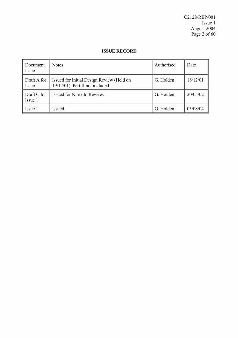
C2128/REP/001 Issue 1
August 2004 Page 2 of 60
ISSUE RECORD
Document Issue
Notes Authorised Date
Draft A for Issue 1
Issued for Initial Design Review (Held on 19/12/01), Part II not included.
G. Holden 18/12/01
Draft C for Issue 1
Issued for Nirex to Review. G. Holden 20/05/02
Issue 1 Issued G. Holden 03/08/04

C2128/REP/001 Issue 1
August 2004 Page 3 of 60
SUMMARY
Nirex requires that a lifting frame is designed for the handling of SWTC285 and that concepts/schemes from which details could be produced are developed. This report details the development of Gravatom Engineering Systems proposal. Part I of the report outlines the concepts for the lifting frame presented at an initial design review at Nirex on 19/12/01. The main principles of the design scheme were discussed and a preferred design was selected. Part II of the report details the design development of the preferred concept. However, the calculations presented in appendix 1 found that the preferred design developed high stresses due to eccentric loading. It was not possible to manufacture the preferred design from standard stainless steel sections so the design was rationalised to eliminate the eccentric loading. Appendix 2 presents the design calculations on the rationalised design. The final design proposal comprises a pin jointed cruciform frame with lateral restraints. The frame members are manufactured from standard stainless steel tubing the sizes of which are detailed on scheme drawing number 1C2128/PROP/01 Iss 0. The centre column of the frame incorporates a lifting feature for a standard crane hook however this could easily be modified to incorporate a pintle. Additionally four other lifting points are provided if a four point lift is required these lifting points could easily be modified to incorporate twist lock casting if required.
C2128/REP/001 Issue 1
August 2004 Page 4 of 60
CONTENTS Issue Record ...................................................................................................................... 2 Summary............................................................................................................................ 3 Contents ............................................................................................................................. 4 References .......................................................................................................................... 6 Introduction - Aim........................................................................................................... 7
- Brief .......................................................................................................... 7 - Background Information & Specifications............................................... 7
Part I:- INITIAL CONCEPT SELECTION 1.0 Initial Design Ideas ..................................................................................................... 9 1.1 - Frame Configuration .......................................................................... 9 1.2 - Crane/Frame Interface Lifting point................................................... 11 1.3 - Location Aids ..................................................................................... 12 1.4 - Lifting Pin Mechanism....................................................................... 15 1.5 – Additional Features............................................................................ 21 2.0 Supporting Calculations and Information................................................................ 22 2.1 – Tolerance Build Up and Frame Location .......................................... 22 2.2 – Pin/Lift Point Initial Stress Analysis ................................................. 23 2.3 – Initial Frame Calculations ................................................................. 27 3.0 Proposed Concept Selection ...................................................................................... 38 3.1 – Frame Design Selection..................................................................... 39 3.2 – Location Aid selection....................................................................... 44 3.3 – Lifting Pin Mechanism Selection ...................................................... 45 4.0 Design Recommendation ............................................................................................ 47 Part II:- SCHEME DEVELOPMENT 5.0 Initial Design Review .................................................................................................. 48 5.1 – Lifting Frame ..................................................................................... 48 5.2 – Lifting Pin Mechanism ...................................................................... 48 5.3 – Location Aid ...................................................................................... 48 6.0 Frame Design Philosophy ........................................................................................... 49 6.1 – Initial Design Concept ....................................................................... 49 6.2 – Rationalised Design Philosophy........................................................ 51 6.2 – Lifting Mechanism............................................................................. 55 6.4 – Location Accuracy and Tolerances ................................................... 56 6.5 – Fatigue ............................................................................................... 57 6.6 – Safety ................................................................................................. 57

C2128/REP/001 Issue 1
August 2004 Page 5 of 60
7.0 Design Proposal ........................................................................................................... 58 7.1 – Description......................................................................................... 58 7.2 – Discussion.......................................................................................... 59 APPENDICES Appendix 1 – Abandoned Frame Design Appendix 2 – Frame Design Calculations

C2128/REP/001 Issue 1
August 2004 Page 6 of 60
REFERENCES 1. BS 2573: Part 1, British Standard, Rules for the design of cranes. Part 1. Specification for
classification, stress calculations and design criteria for structures. 2. Roark’s Formulas for Stress and Strain, 6th Edition, Warren C Young, McGraw-Hill
International Editions, General Engineering Series. 3. BS 4848 Hot Rolled Structural Steel Sections. 4. BS 5950 Part 1, British Standard, Structural use of – steelwork in building, Part 1: Code of
practice for design – Rolled and Welded Sections. 5. UK Steel Association, Steel Specifications, 10th Edition. 6. Minutes of Initial Design Scheme Review Meeting held at Nirex, ref: C2128/MIN002,
19/12/01. 7. NIREX Report, SWTC-285 detailed design: Interim Report, reference WP:REP(01)04 issue
Draft 1.

C2128/REP/001 Issue 1
August 2004 Page 7 of 60
INTRODUCTION AIM To prepare a design scheme for a frame to lift package design SWTC285. BRIEF Nirex Ltd has developed a concept for a shielded overpack for the transport of waste drums
to the repository. This overpack is designated SWTC285 and is shown on drawing number T/DRG/0000001 Issue P/05.
Nirex requires that a lifting frame is designed for the handling of SWTC285 and that
concepts/schemes from which details could be produced are developed.
This report outlines the work conducted to prepare the proposed concept/scheme. The report is presented in two parts, Part I – Initial Concept Selection (prior to design review) and Part II - Design Development and Scheming.
BACKGROUND INFORMATION AND SPECIFICATIONS A lifting frame for the SWTC285 will need to:
• have a lifting capacity of 65 tonnes (638 kN).
• be remotely locatable on this container. (The crane has a positional accuracy within a square of side 10mm).
• be easily maintained with minimal wear and maintenance.
• (Ideally) be capable of totally remote operation ultimately, manual pin engagement is acceptable at present.
• lift from the 4 holes on the container top
• have a design life of 30 years.
• assume worst case of only being supported by two lifting points.
• apply the load vertically to the lifting lug/impact ears.
• be suitable for 832 lifts per year (25,000 in total).
• provide a reasonable amount of compliance in the design to distribute loads.
• operate within a design temperature range -10°C to +40°C.
• be designed to BS 2573 Crane Rules (reference 1).
C2128/REP/001 Issue 1
August 2004 Page 8 of 60
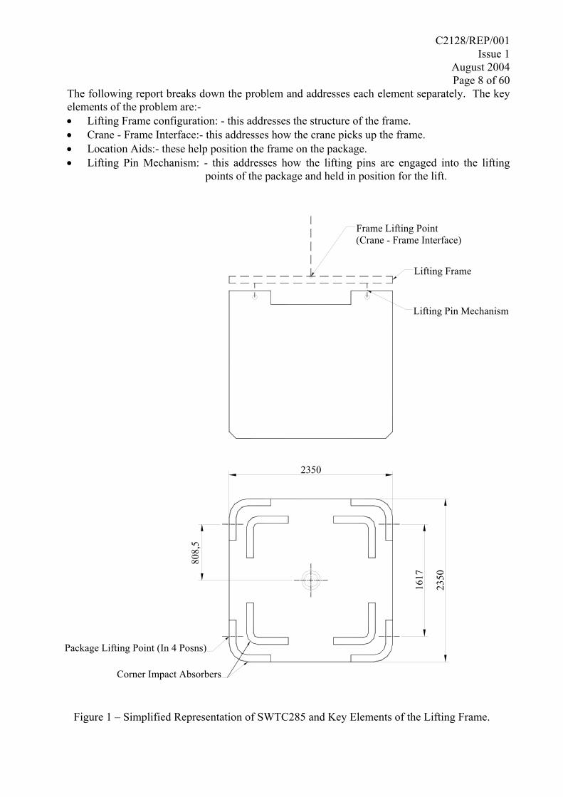
The following report breaks down the problem and addresses each element separately. The key elements of the problem are:- • Lifting Frame configuration: - this addresses the structure of the frame. • Crane - Frame Interface:- this addresses how the crane picks up the frame. • Location Aids:- these help position the frame on the package. • Lifting Pin Mechanism: - this addresses how the lifting pins are engaged into the lifting
points of the package and held in position for the lift.
1617
2350
808,
5
2350
Package Lifting Point (In 4 Posns)
Corner Impact Absorbers
Lifting Pin Mechanism
Lifting Frame
Frame Lifting Point (Crane - Frame Interface)
Figure 1 – Simplified Representation of SWTC285 and Key Elements of the Lifting Frame.
C2128/REP/001 Issue 1
August 2004 Page 9 of 60
PART I:- INITIAL CONCEPT SELECTION 1.0 INITIAL DESIGN IDEAS 1.1 FRAME CONFIGURATION 1.1.1 Design Philosophy
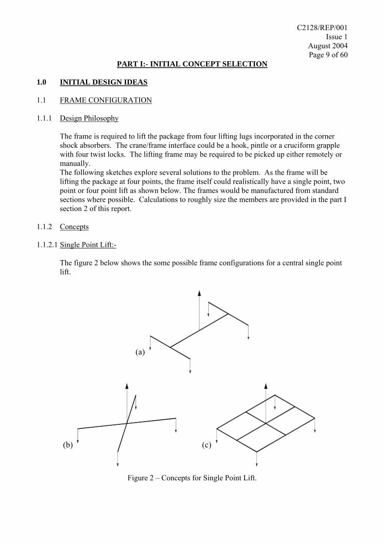
The frame is required to lift the package from four lifting lugs incorporated in the corner shock absorbers. The crane/frame interface could be a hook, pintle or a cruciform grapple with four twist locks. The lifting frame may be required to be picked up either remotely or manually. The following sketches explore several solutions to the problem. As the frame will be lifting the package at four points, the frame itself could realistically have a single point, two point or four point lift as shown below. The frames would be manufactured from standard sections where possible. Calculations to roughly size the members are provided in the part I section 2 of this report.
1.1.2 Concepts 1.1.2.1 Single Point Lift:-
The figure 2 below shows the some possible frame configurations for a central single point lift.
(a)
(b) (c)
Figure 2 – Concepts for Single Point Lift.
C2128/REP/001 Issue 1
August 2004 Page 10 of 60
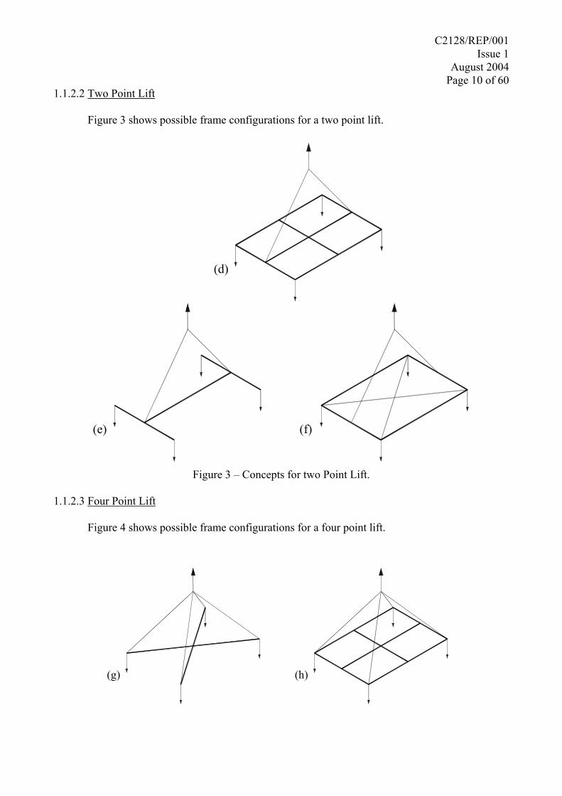
1.1.2.2 Two Point Lift
Figure 3 shows possible frame configurations for a two point lift.
(d)
(e) (f)
Figure 3 – Concepts for two Point Lift.
1.1.2.3 Four Point Lift
Figure 4 shows possible frame configurations for a four point lift.
(g) (h)
C2128/REP/001 Issue 1
August 2004 Page 11 of 60
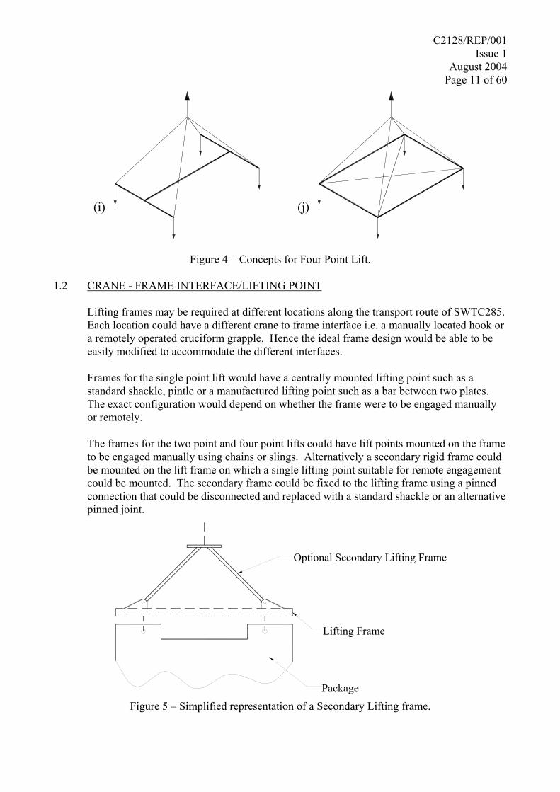
(j)(i)
Figure 4 – Concepts for Four Point Lift.
1.2 CRANE - FRAME INTERFACE/LIFTING POINT
Lifting frames may be required at different locations along the transport route of SWTC285. Each location could have a different crane to frame interface i.e. a manually located hook or a remotely operated cruciform grapple. Hence the ideal frame design would be able to be easily modified to accommodate the different interfaces.
Frames for the single point lift would have a centrally mounted lifting point such as a standard shackle, pintle or a manufactured lifting point such as a bar between two plates. The exact configuration would depend on whether the frame were to be engaged manually or remotely.
The frames for the two point and four point lifts could have lift points mounted on the frame to be engaged manually using chains or slings. Alternatively a secondary rigid frame could be mounted on the lift frame on which a single lifting point suitable for remote engagement could be mounted. The secondary frame could be fixed to the lifting frame using a pinned connection that could be disconnected and replaced with a standard shackle or an alternative pinned joint.
Package
Lifting Frame
Optional Secondary Lifting Frame
Figure 5 – Simplified representation of a Secondary Lifting frame.
C2128/REP/001 Issue 1
August 2004 Page 12 of 60
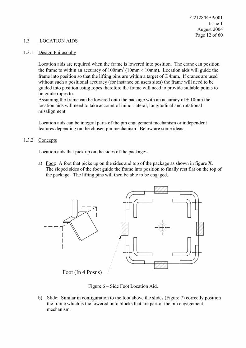
1.3 LOCATION AIDS 1.3.1 Design Philosophy
Location aids are required when the frame is lowered into position. The crane can position the frame to within an accuracy of 100mm2 (10mm × 10mm). Location aids will guide the frame into position so that the lifting pins are within a target of ∅4mm. If cranes are used without such a positional accuracy (for instance on users sites) the frame will need to be guided into position using ropes therefore the frame will need to provide suitable points to tie guide ropes to. Assuming the frame can be lowered onto the package with an accuracy of ± 10mm the location aids will need to take account of minor lateral, longitudinal and rotational misalignment.
Location aids can be integral parts of the pin engagement mechanism or independent features depending on the chosen pin mechanism. Below are some ideas;
1.3.2 Concepts
Location aids that pick up on the sides of the package:-
a) Foot: A foot that picks up on the sides and top of the package as shown in figure X. The sloped sides of the foot guide the frame into position to finally rest flat on the top of the package. The lifting pins will then be able to be engaged.
Foot (In 4 Posns)
Figure 6 – Side Foot Location Aid.
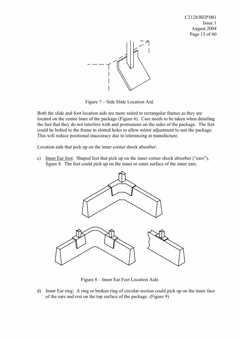
b) Slide: Similar in configuration to the foot above the slides (Figure 7) correctly position
the frame which is the lowered onto blocks that are part of the pin engagement mechanism.
C2128/REP/001 Issue 1
August 2004 Page 13 of 60
Figure 7 – Side Slide Location Aid. Both the slide and foot location aids are more suited to rectangular frames as they are
located on the centre lines of the package (Figure 6). Care needs to be taken when detailing the feet that they do not interfere with and protrusions on the sides of the package. The feet could be bolted to the frame in slotted holes to allow minor adjustment to suit the package. This will reduce positional inaccuracy due to tolerancing at manufacture.
Location aids that pick up on the inner corner shock absorber:
c) Inner Ear foot: Shaped feet that pick up on the inner corner shock absorber (“ears”),
figure 8. The feet could pick up on the inner or outer surface of the inner ears.
Figure 8 – Inner Ear Feet Location Aids
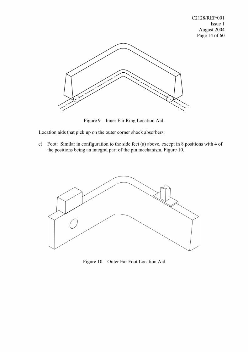
d) Inner Ear ring: A ring or broken ring of circular section could pick up on the inner face
of the ears and rest on the top surface of the package. (Figure 9)
C2128/REP/001 Issue 1
August 2004 Page 14 of 60
Figure 9 – Inner Ear Ring Location Aid. Location aids that pick up on the outer corner shock absorbers:
e) Foot: Similar in configuration to the side feet (a) above, except in 8 positions with 4 of
the positions being an integral part of the pin mechanism, Figure 10.
Figure 10 – Outer Ear Foot Location Aid
C2128/REP/001 Issue 1
August 2004 Page 15 of 60
1.4 LIFTING PIN MECHANISM 1.4.1 Design Philosophy
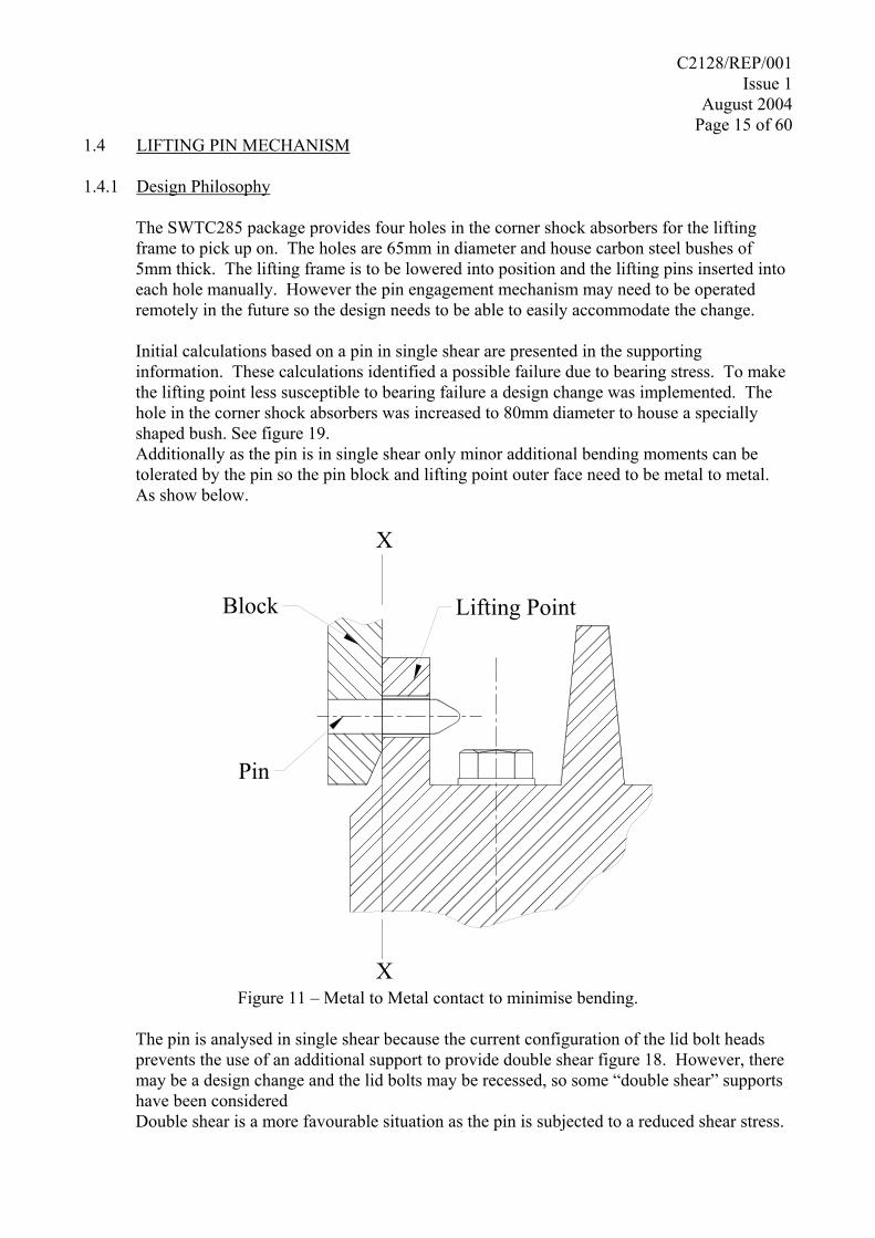
The SWTC285 package provides four holes in the corner shock absorbers for the lifting frame to pick up on. The holes are 65mm in diameter and house carbon steel bushes of 5mm thick. The lifting frame is to be lowered into position and the lifting pins inserted into each hole manually. However the pin engagement mechanism may need to be operated remotely in the future so the design needs to be able to easily accommodate the change.
Initial calculations based on a pin in single shear are presented in the supporting information. These calculations identified a possible failure due to bearing stress. To make the lifting point less susceptible to bearing failure a design change was implemented. The hole in the corner shock absorbers was increased to 80mm diameter to house a specially shaped bush. See figure 19. Additionally as the pin is in single shear only minor additional bending moments can be tolerated by the pin so the pin block and lifting point outer face need to be metal to metal. As show below.
Block
Pin
Lifting Point
X
X Figure 11 – Metal to Metal contact to minimise bending.
The pin is analysed in single shear because the current configuration of the lid bolt heads prevents the use of an additional support to provide double shear figure 18. However, there may be a design change and the lid bolts may be recessed, so some “double shear” supports have been considered Double shear is a more favourable situation as the pin is subjected to a reduced shear stress.
C2128/REP/001 Issue 1
August 2004 Page 16 of 60
1.4.2 Concepts
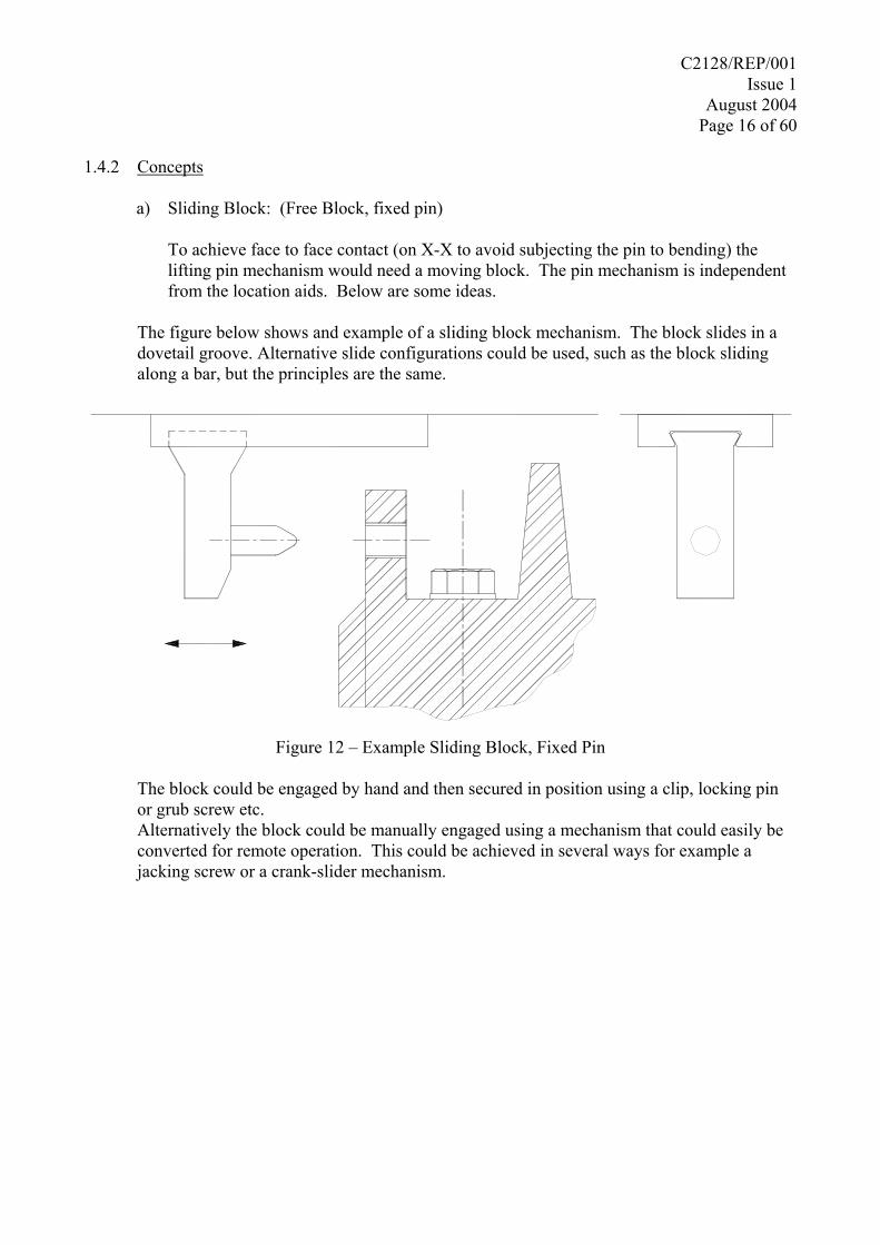
a) Sliding Block: (Free Block, fixed pin)
To achieve face to face contact (on X-X to avoid subjecting the pin to bending) the lifting pin mechanism would need a moving block. The pin mechanism is independent from the location aids. Below are some ideas.
The figure below shows and example of a sliding block mechanism. The block slides in a
dovetail groove. Alternative slide configurations could be used, such as the block sliding along a bar, but the principles are the same.
Figure 12 – Example Sliding Block, Fixed Pin
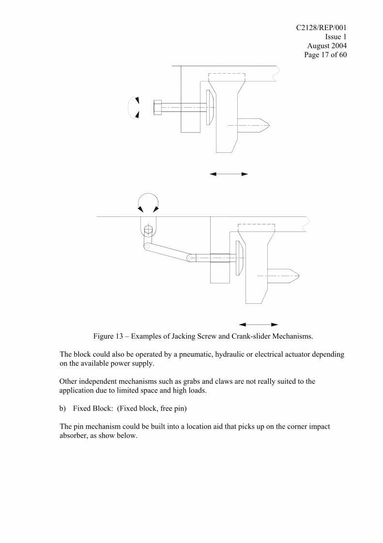
The block could be engaged by hand and then secured in position using a clip, locking pin or grub screw etc. Alternatively the block could be manually engaged using a mechanism that could easily be converted for remote operation. This could be achieved in several ways for example a jacking screw or a crank-slider mechanism.
C2128/REP/001 Issue 1
August 2004 Page 17 of 60
Figure 13 – Examples of Jacking Screw and Crank-slider Mechanisms.
The block could also be operated by a pneumatic, hydraulic or electrical actuator depending on the available power supply.
Other independent mechanisms such as grabs and claws are not really suited to the application due to limited space and high loads.
b) Fixed Block: (Fixed block, free pin)
The pin mechanism could be built into a location aid that picks up on the corner impact absorber, as show below.
C2128/REP/001 Issue 1
August 2004 Page 18 of 60
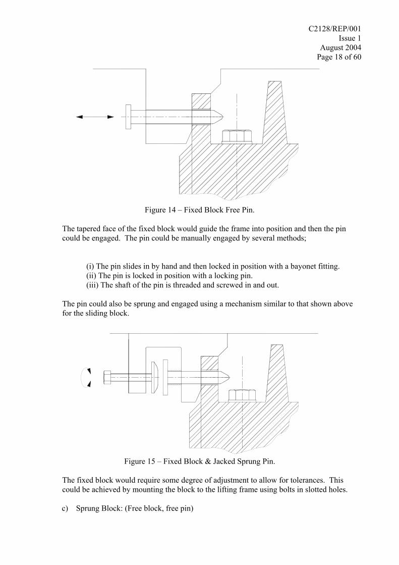
Figure 14 – Fixed Block Free Pin.
The tapered face of the fixed block would guide the frame into position and then the pin
could be engaged. The pin could be manually engaged by several methods;
(i) The pin slides in by hand and then locked in position with a bayonet fitting. (ii) The pin is locked in position with a locking pin. (iii) The shaft of the pin is threaded and screwed in and out.
The pin could also be sprung and engaged using a mechanism similar to that shown above
for the sliding block.
Figure 15 – Fixed Block & Jacked Sprung Pin.
The fixed block would require some degree of adjustment to allow for tolerances. This
could be achieved by mounting the block to the lifting frame using bolts in slotted holes.
c) Sprung Block: (Free block, free pin)
C2128/REP/001 Issue 1
August 2004 Page 19 of 60
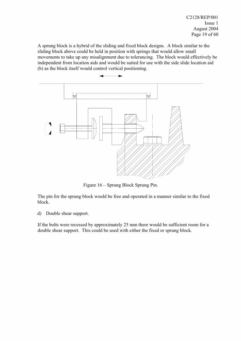
A sprung block is a hybrid of the sliding and fixed block designs. A block similar to the
sliding block above could be held in position with springs that would allow small movements to take up any misalignment due to tolerancing. The block would effectively be independent from location aids and would be suited for use with the side slide location aid (b) as the block itself would control vertical positioning.
Figure 16 – Sprung Block Sprung Pin.
The pin for the sprung block would be free and operated in a manner similar to the fixed
block.
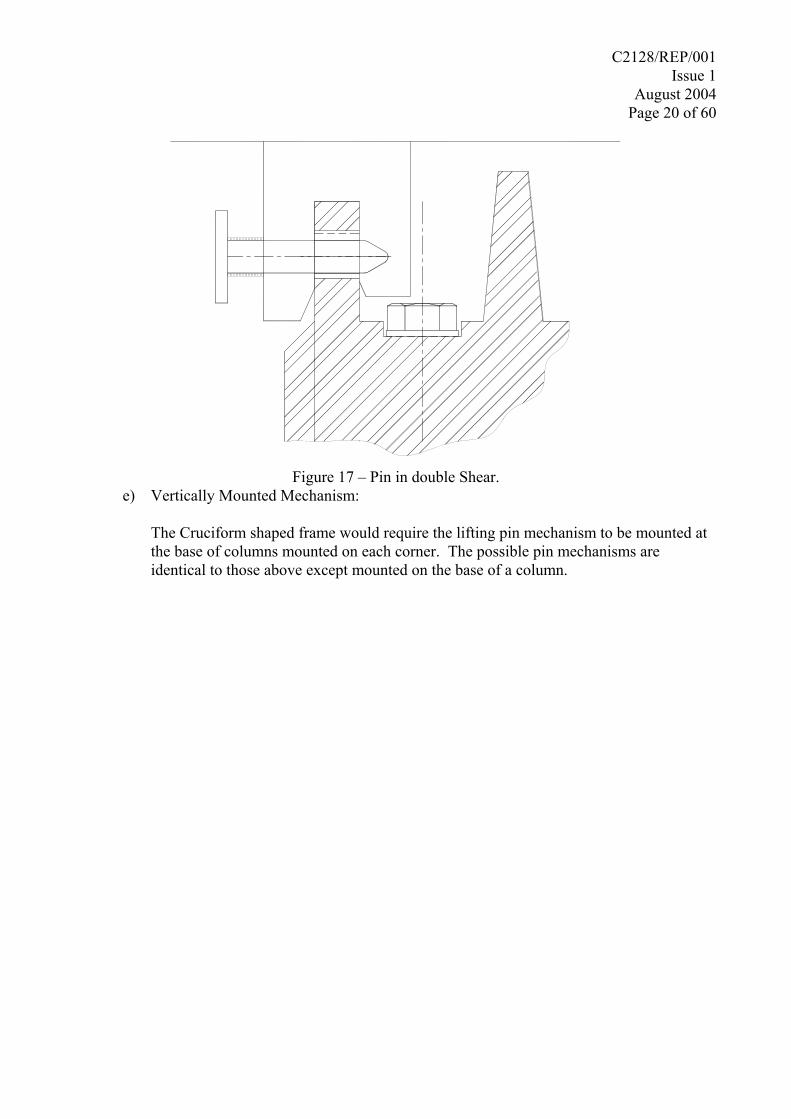
d) Double shear support.
If the bolts were recessed by approximately 25 mm there would be sufficient room for a double shear support. This could be used with either the fixed or sprung block.
C2128/REP/001 Issue 1
August 2004 Page 20 of 60
Figure 17 – Pin in double Shear.
e) Vertically Mounted Mechanism: The Cruciform shaped frame would require the lifting pin mechanism to be mounted at the base of columns mounted on each corner. The possible pin mechanisms are identical to those above except mounted on the base of a column.
C2128/REP/001 Issue 1
August 2004 Page 21 of 60
1.5 ADDITIONAL FEATURES 1.5.1 Anchor points As mentioned previously some cranes used to lift the SWTC285 may require assistance
when positioning the frame onto the package. So the frame will require anchor points to attach guide ropes.
1.5.2 Legs The frame is likely to be placed on the floor when not in use. As the pin engagement
mechanism and location aids will be below the frame legs will be required to protect them from damage.
1.5.3 Material Considerations The service environment could vary from a warm dry repository to a coastal environment,
the selection of any materials would need to take this into account. The main body of the frame ideally would be manufactured from standard carbon steel
sections. As they are relatively cheap and readily available. The steel would then be painted to prevent excessive corrosion. The paint would have to be re-applied at intervals dependent on service environment. Typically every 5 years.
Alternatively the frame could be manufactured from Stainless Steel, or carbon steel
protected in another manner. So that NDT inspection could be carried out without paint removal and there would be no need to maintain the finish.
The lifting pin requires to be manufactured from a strong and hard stainless steel, to prevent
corrosion and be able to withstand the high bearing and shear stresses. Any slides for the blocks would have to be well lubricated stainless steel to prevent corrosion and galling. The slide faces themselves would most likely need to be surface hardened. A means of re-applying lubrication to the slides would also be required.
1.5.4 Sacrificial Bushes The lifting point in the frame could be fitted with sacrificial bushes, similar to those in the
package lifting points, for ease of maintenance.

C2128/REP/001 Issue 1
August 2004 Page 22 of 60
2.0 SUPPORTING CALCULATIONS AND INFORMATION 2.1 TOLERANCE BUILD UP AND FRAME LOCATION
Assuming the SWTC285 drawings dimension the hole from the top face of the corner impact absorber and the sidewall of the package, the best reasonable positional tolerance for the hole centreline location is within a diameter of 2mm.
Not knowing the actual configuration of the lift frame the best reasonable positional tolerance for the pin centreline location relative to the location aids is within a diameter of 2mm.
Additionally the maximum reasonable accuracy with which the frame can be positioned on the SWTC285 is ±2mm
Hence as a minimum the design must account for a misalignment of the centrelines of the pin and hole within a diameter of 8mm.
C2128/REP/001 Issue 1
August 2004 Page 23 of 60
2.2 PIN/LIFT POINT INITIAL STRESS ANALYSIS 2.2.1 Loading
To estimate the sizes of the lifting pin the following assumptions were used:
Assume the load is supported on only two lifting points. Assume a 100% snatch factor is applied. Hence the load on each lifting pin is 638kN.
Figure 18 shows a cross section of the corner shock absorbers and lifting point.
25
200
75
92,5
Ø65
207
Figure 18 – SWTC285 Lifting Point.
2.2.2 Pin/Bush Bearing Stress
Reference 1 (para 5.1.6) takes the basic bearing stress on the projected area of fixed axles and pins. This must be assuming that permanent deformation takes place to allow the contact area to approach the projected area. For this application it is not desirable for the pin to permanently deform. Hence the bearing stress must be calculated using the actual contact area.
Ref 2, page 651 gives the maximum bearing stress for a cylinder inside another cylinder as;
D
c KpE0.591σMax =
Where,
C2128/REP/001 Issue 1
August 2004 Page 24 of 60
LPp =
21
21D DD
DDK−
=
Assuming; E = Elastic Modulus of the Bush and Pin, assume = 205×103 N/mm2. D1 = Internal Diameter of the Bush = 55 mm D2 = Diameter of the Pin = 50 mm P = Lifting Load = 638×103 N L = Lug width = 75 mm
Hence,
550K05550555K
DDDDK
D
D
21
21D
=−×
=
−=
2c
33
c
Dc
mmN1052σMax75550
10205106380.591σMax
KpE0.591σMax
=
××××
=
=
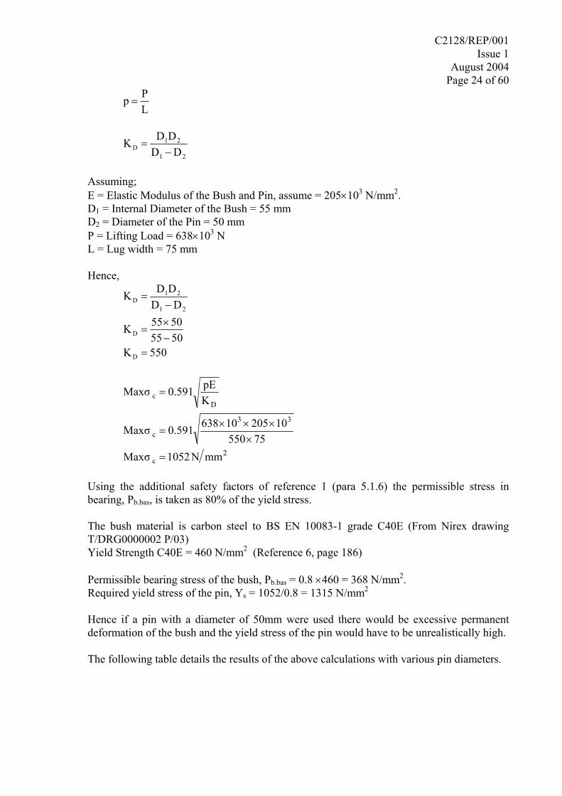
Using the additional safety factors of reference 1 (para 5.1.6) the permissible stress in bearing, Pb.bas, is taken as 80% of the yield stress.
The bush material is carbon steel to BS EN 10083-1 grade C40E (From Nirex drawing T/DRG0000002 P/03) Yield Strength C40E = 460 N/mm2 (Reference 6, page 186)
Permissible bearing stress of the bush, Pb.bas = 0.8 ×460 = 368 N/mm2. Required yield stress of the pin, Ys = 1052/0.8 = 1315 N/mm2
Hence if a pin with a diameter of 50mm were used there would be excessive permanent deformation of the bush and the yield stress of the pin would have to be unrealistically high.
The following table details the results of the above calculations with various pin diameters.
C2128/REP/001 Issue 1
August 2004 Page 25 of 60
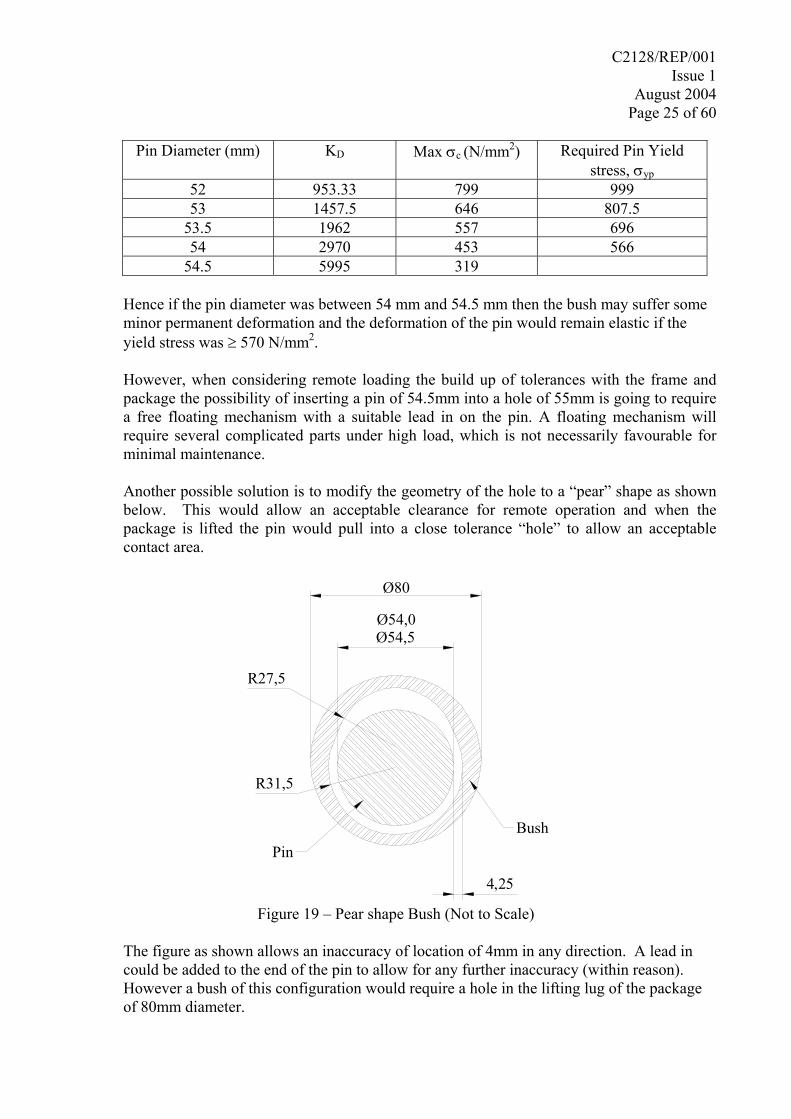
Pin Diameter (mm) KD Max σc (N/mm2) Required Pin Yield
stress, σyp 52 953.33 799 999 53 1457.5 646 807.5
53.5 1962 557 696 54 2970 453 566
54.5 5995 319
Hence if the pin diameter was between 54 mm and 54.5 mm then the bush may suffer some minor permanent deformation and the deformation of the pin would remain elastic if the yield stress was ≥ 570 N/mm2.
However, when considering remote loading the build up of tolerances with the frame and package the possibility of inserting a pin of 54.5mm into a hole of 55mm is going to require a free floating mechanism with a suitable lead in on the pin. A floating mechanism will require several complicated parts under high load, which is not necessarily favourable for minimal maintenance.
Another possible solution is to modify the geometry of the hole to a “pear” shape as shown below. This would allow an acceptable clearance for remote operation and when the package is lifted the pin would pull into a close tolerance “hole” to allow an acceptable contact area.
BushPin
4,25
Ø80
Ø54,0Ø54,5
R31,5
R27,5
Figure 19 – Pear shape Bush (Not to Scale)
The figure as shown allows an inaccuracy of location of 4mm in any direction. A lead in could be added to the end of the pin to allow for any further inaccuracy (within reason). However a bush of this configuration would require a hole in the lifting lug of the package of 80mm diameter.
C2128/REP/001 Issue 1
August 2004 Page 26 of 60
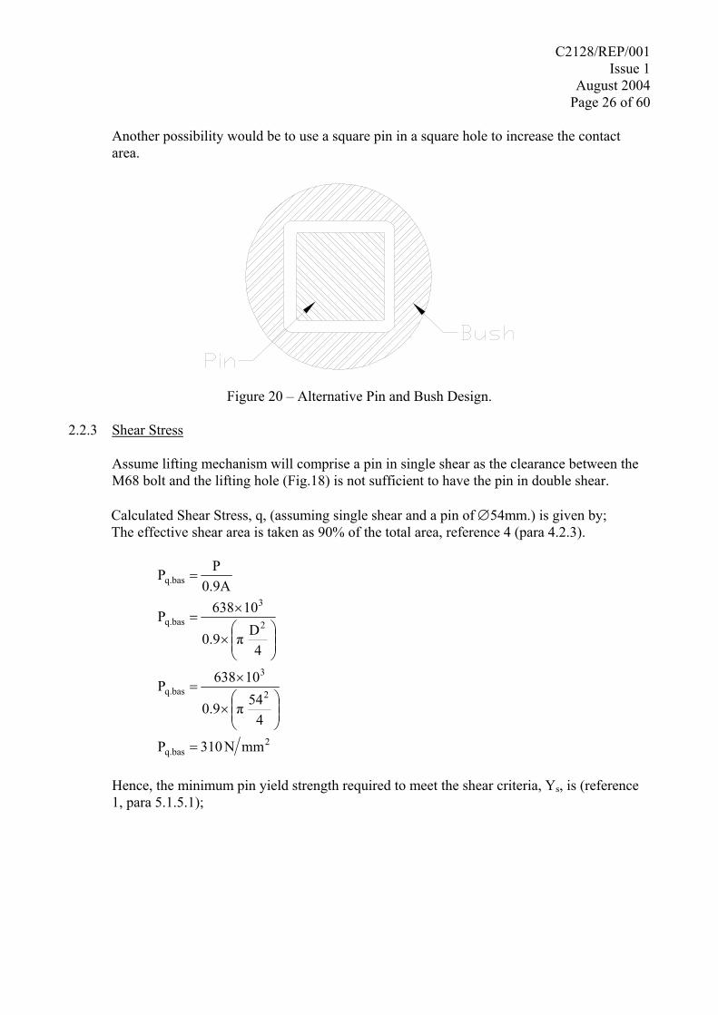
Another possibility would be to use a square pin in a square hole to increase the contact area.
Figure 20 – Alternative Pin and Bush Design.
2.2.3 Shear Stress
Assume lifting mechanism will comprise a pin in single shear as the clearance between the M68 bolt and the lifting hole (Fig.18) is not sufficient to have the pin in double shear.
Calculated Shear Stress, q, (assuming single shear and a pin of ∅54mm.) is given by; The effective shear area is taken as 90% of the total area, reference 4 (para 4.2.3).
2q.bas
2
3
q.bas
2
3
q.bas
q.bas
mmN310P
454π0.9
10638P
4Dπ0.9
10638P
0.9APP
=
⎟⎟⎠
⎞⎜⎜⎝
⎛×
×=
⎟⎟⎠
⎞⎜⎜⎝
⎛×
×=
=
Hence, the minimum pin yield strength required to meet the shear criteria, Ys, is (reference 1, para 5.1.5.1);
C2128/REP/001 Issue 1
August 2004 Page 27 of 60
2s
s
q.bass
mmN838Y0.37310Y
0.37P
Y
=
=
=
2.3 INITIAL FRAME CALCULATIONS
To estimate the sizes of the frame members the following assumptions were used:
Assume the load is supported on only two lifting points. Assume a 100% snatch factor is applied. Hence the load on each lifting point is 638kN.
The following cases were analysed;
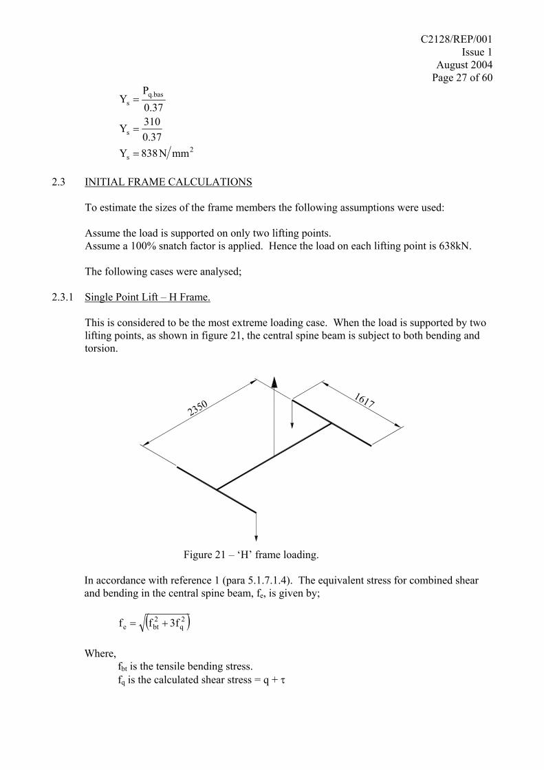
2.3.1 Single Point Lift – H Frame.
This is considered to be the most extreme loading case. When the load is supported by two lifting points, as shown in figure 21, the central spine beam is subject to both bending and torsion.
23501617
Figure 21 – ‘H’ frame loading.
In accordance with reference 1 (para 5.1.7.1.4). The equivalent stress for combined shear and bending in the central spine beam, fe, is given by;
( )2
q2bte 3fff +=
Where,
fbt is the tensile bending stress. fq is the calculated shear stress = q + τ
C2128/REP/001 Issue 1
August 2004 Page 28 of 60
and, τ = Torsional Shear stress q = Direct Shear Stress.
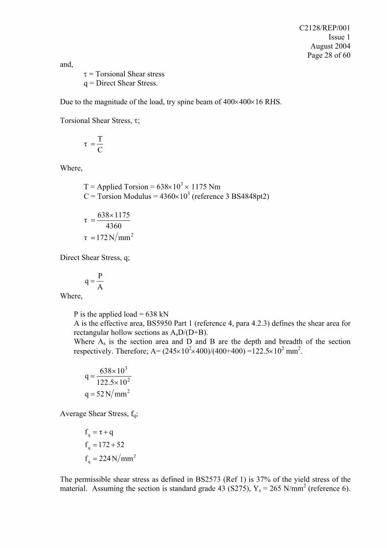
Due to the magnitude of the load, try spine beam of 400×400×16 RHS.
Torsional Shear Stress, τ;
CTτ =
Where,
T = Applied Torsion = 638×103 × 1175 Nm C = Torsion Modulus = 4360×103 (reference 3 BS4848pt2)
2mmN172τ
43601175638τ
=
×=
Direct Shear Stress, q;
APq =
Where,
P is the applied load = 638 kN A is the effective area, BS5950 Part 1 (reference 4, para 4.2.3) defines the shear area for
rectangular hollow sections as AsD/(D+B). Where As is the section area and D and B are the depth and breadth of the section
respectively. Therefore; A= (245×102×400)/(400+400) =122.5×102 mm2.
2
2
3
mmN52q105.221
10638q
=××
=
Average Shear Stress, fq;
2
q
q
q
mmN224f
52172f
qτf
=
+=
+=
The permissible shear stress as defined in BS2573 (Ref 1) is 37% of the yield stress of the material. Assuming the section is standard grade 43 (S275), Ys = 265 N/mm2 (reference 6).
C2128/REP/001 Issue 1
August 2004 Page 29 of 60
Hence the permissible Shear Stress is fq = 0.37×265 = 98 N/mm2. Therefore, the spine beam would not satisfy the shear criteria and standard box section would not be acceptable. To assist in the selection of a suitable section the calculations for the bending stress and maximum stress were completed for the 400×400×16 RHS as shown below. Tensile Bending Stress, fbt;
Z
Mf bbt =
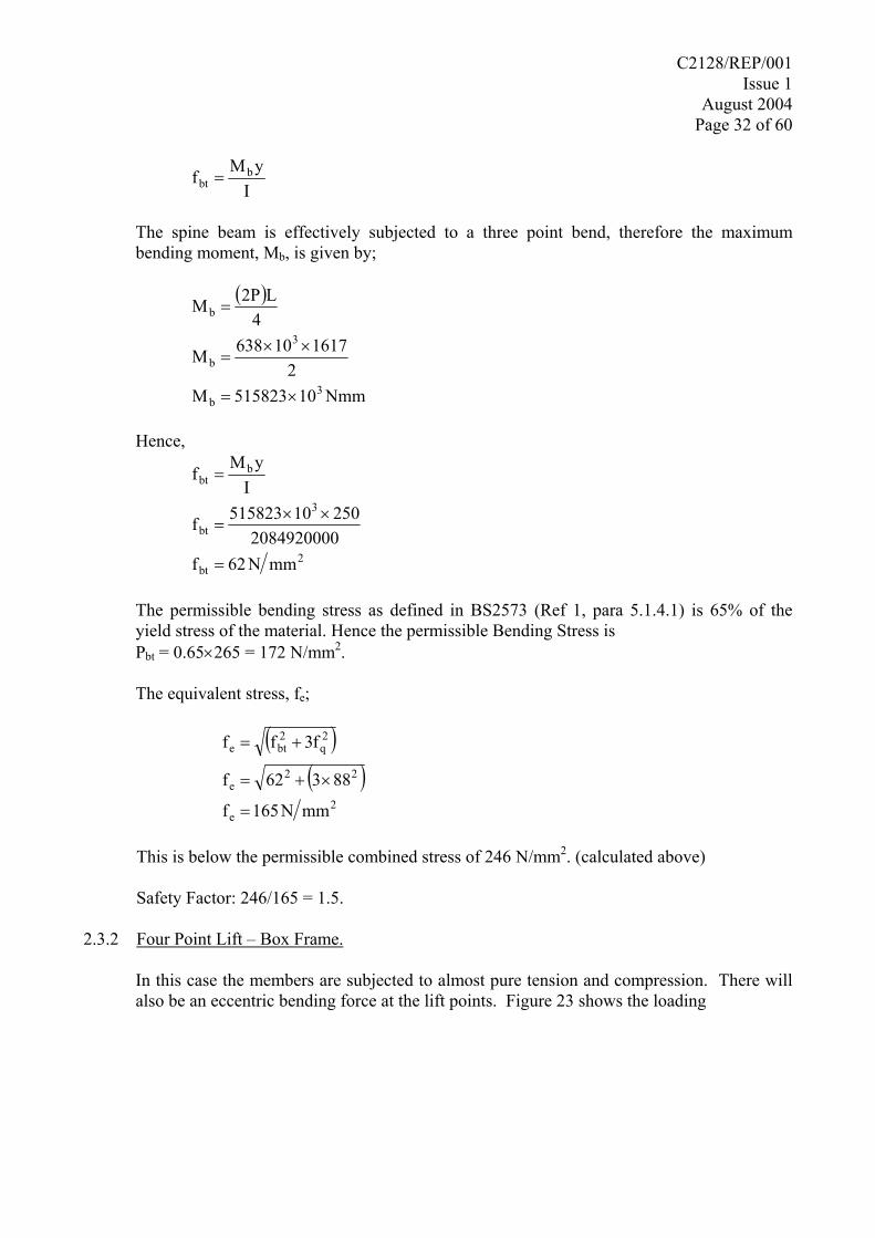
Where, The spine beam is effectively subjected to a three point bend, therefore the maximum bending moment, Mb, is given by;
( )
Nmm10515823M2
161710638M
4L2PM
3b
3
b
b
×=
××=
=
The elastic modulus, Z = 3000 cm3, (Reference 3)
2bt
3
3
bt
bbt
mmN172f10300010515823f
ZMf
=××
=
=
The permissible bending stress as defined in BS2573 (Ref 1, para 5.1.4.1) is 65% of the yield stress of the material. Hence the permissible Bending Stress is Pbt = 0.65×265 = 172 N/mm2. Therefore, the spine beam is on the limit of it’s permissible bending stress. The equivalent stress, fe (reference 1, para 5.1.7.1.4);
( )
( )2
e
22e
2q
2bte
mmN244f
2423172f
f3ff
=
×+=
+=
The permissible equivalent stress for combined bending and shear as defined in reference 1 (para 5.1.7.2) is 93% of the yield stress of the material. Hence the permissible maximum combined stress is fe.max= 0.93×265 = 246 N/mm2.
C2128/REP/001 Issue 1
August 2004 Page 30 of 60
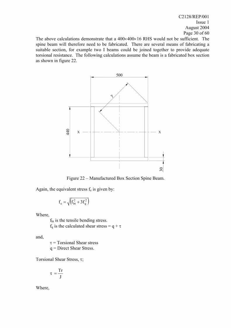
The above calculations demonstrate that a 400×400×16 RHS would not be sufficient. The spine beam will therefore need to be fabricated. There are several means of fabricating a suitable section, for example two I beams could be joined together to provide adequate torsional resistance. The following calculations assume the beam is a fabricated box section as shown in figure 22.
500
y
440
30
X X
Figure 22 – Manufactured Box Section Spine Beam.
Again, the equivalent stress fe is given by:
( )2
q2bte 3fff +=
Where,
fbt is the tensile bending stress. fq is the calculated shear stress = q + τ
and,
τ = Torsional Shear stress q = Direct Shear Stress.
Torsional Shear Stress, τ;
J
Trτ =
Where,
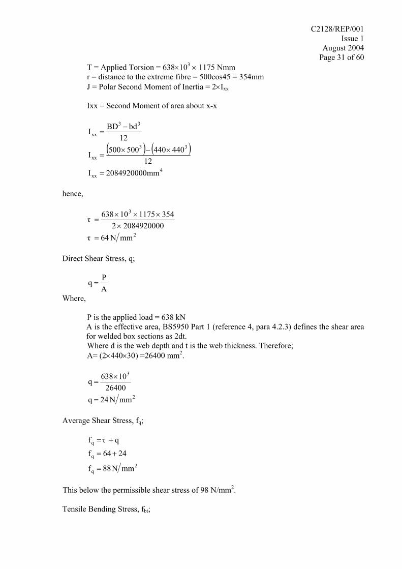
C2128/REP/001 Issue 1
August 2004 Page 31 of 60
T = Applied Torsion = 638×103 × 1175 Nmm r = distance to the extreme fibre = 500cos45 = 354mm J = Polar Second Moment of Inertia = 2×Ixx Ixx = Second Moment of area about x-x
( ) ( )4
xx
33
xx
33
xx
mm0849200002I12
440440500500I
12bdBDI
=
×−×=
−=
hence,
2
3
mmN64τ08492000022
354117510638τ
=×
×××=
Direct Shear Stress, q;
APq =
Where,
P is the applied load = 638 kN A is the effective area, BS5950 Part 1 (reference 4, para 4.2.3) defines the shear area for welded box sections as 2dt.
Where d is the web depth and t is the web thickness. Therefore; A= (2×440×30) =26400 mm2.
2
3
mmN42q26400
10638q
=
×=
Average Shear Stress, fq;
2
q
q
q
mmN88f
4246f
qτf
=
+=
+=
This below the permissible shear stress of 98 N/mm2.
Tensile Bending Stress, fbt;
C2128/REP/001 Issue 1
August 2004 Page 32 of 60
I
yMf bbt =
The spine beam is effectively subjected to a three point bend, therefore the maximum bending moment, Mb, is given by;
( )
Nmm10515823M2
161710638M
4L2PM
3b
3
b
b
×=
××=
=
Hence,
2bt
3
bt
bbt
mmN26f2084920000
25010515823f
IyMf
=
××=
=
The permissible bending stress as defined in BS2573 (Ref 1, para 5.1.4.1) is 65% of the yield stress of the material. Hence the permissible Bending Stress is Pbt = 0.65×265 = 172 N/mm2.
The equivalent stress, fe;
( )
( )2
e
22e
2q
2bte
mmN165f
88326f
f3ff
=
×+=
+=
This is below the permissible combined stress of 246 N/mm2. (calculated above)
Safety Factor: 246/165 = 1.5. 2.3.2 Four Point Lift – Box Frame.
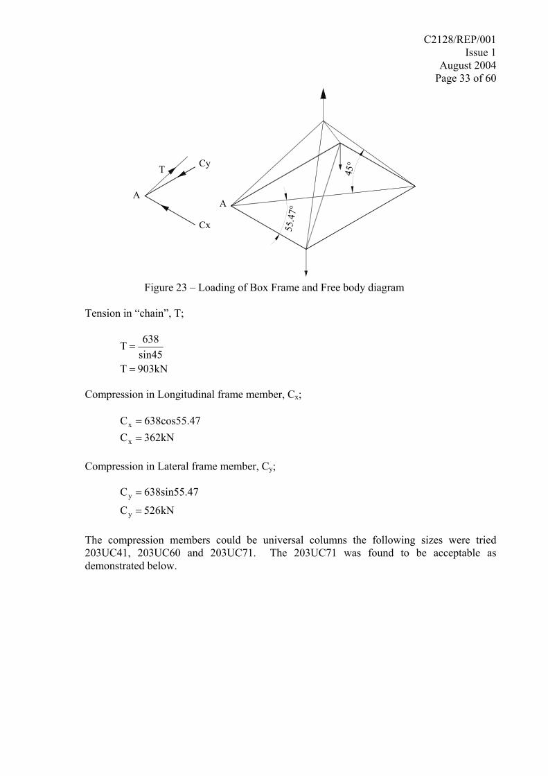
In this case the members are subjected to almost pure tension and compression. There will also be an eccentric bending force at the lift points. Figure 23 shows the loading
C2128/REP/001 Issue 1
August 2004 Page 33 of 60
A
55.4
7°
45°
A
T Cy
Cx
Figure 23 – Loading of Box Frame and Free body diagram
Tension in “chain”, T;
903kNTsin45638T
=
=
Compression in Longitudinal frame member, Cx;
362kNC
7638cos55.4C
x
x
==
Compression in Lateral frame member, Cy;
kN265C
7638sin55.4C
y
y
=
=
The compression members could be universal columns the following sizes were tried 203UC41, 203UC60 and 203UC71. The 203UC71 was found to be acceptable as demonstrated below.
C2128/REP/001 Issue 1
August 2004 Page 34 of 60
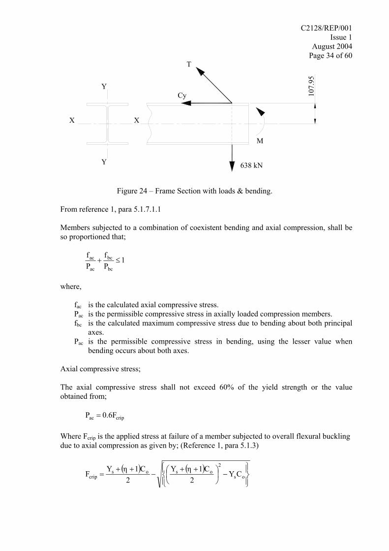
107.
95
M
T
Cy
638 kN
Y
Y
X X
Figure 24 – Frame Section with loads & bending.
From reference 1, para 5.1.7.1.1
Members subjected to a combination of coexistent bending and axial compression, shall be so proportioned that;
1Pf
Pf
bc
bc
ac
ac ≤+
where,
fac is the calculated axial compressive stress. Pac is the permissible compressive stress in axially loaded compression members. fbc is the calculated maximum compressive stress due to bending about both principal
axes. Pac is the permissible compressive stress in bending, using the lesser value when
bending occurs about both axes.
Axial compressive stress;
The axial compressive stress shall not exceed 60% of the yield strength or the value obtained from;
cripac 0.6FP =
Where Fcrip is the applied stress at failure of a member subjected to overall flexural buckling due to axial compression as given by; (Reference 1, para 5.1.3)
( ) ( )⎪⎭
⎪⎬⎫
⎪⎩
⎪⎨⎧
−⎟⎠⎞
⎜⎝⎛ ++
−++
= os
2osos
crip CY2
C1ηY2
C1ηYF
C2128/REP/001 Issue 1
August 2004 Page 35 of 60
where,
Fcrip is the applied stress at failure.
Co is the Euler critical stress ⎟⎟⎠
⎞⎜⎜⎝
⎛= 2
2
sEπ
Ys is the yield stress = 265 N/mm2 E is Young’s modulus = 205×103 N/mm2 η is the Perry coefficient (=α(s-so)×10-3, but > 0) α is the Robertson constant from reference 1 table 11 = 5.5 s is the slenderness ratio (=l/r) so is the limiting slenderness ratio for stub columns
17.5265102050.2π
YE0.2π3
s
=
×=
=
r is the radius of gyration about the appropriate axis = 5.28 cm (Reference 3) l is the effective length relative to the same axis = 1617 mm
hence,
30.625s52.81617s
rls
=
=
=
( )( )
3
3
3o
1072.19η
1017.530.6255.5η
10ssαη
−
−
−
×=
×−=
×−=
and
2157.25C30.625
10205πC
sEπC
o
2
32
o
2
2
o
=
×=
=
Therefore,
C2128/REP/001 Issue 1
August 2004 Page 36 of 60
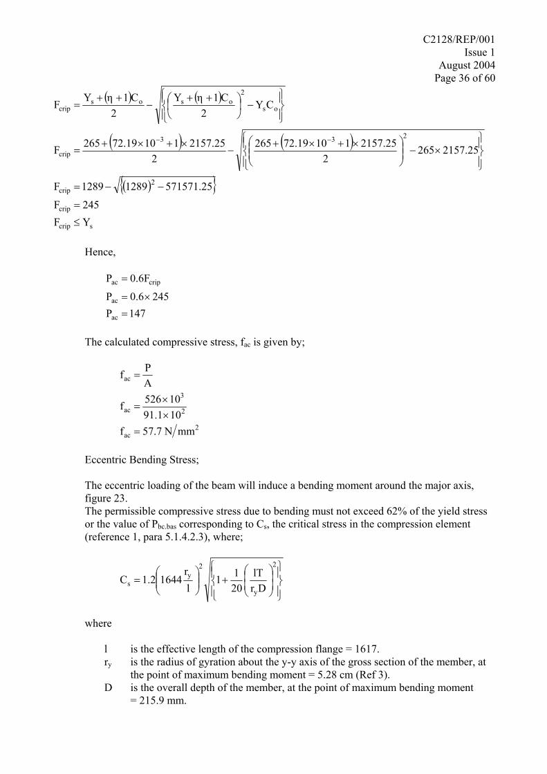
( ) ( )
( ) ( )
( ){ }245F
571571.2512891289F
2157.252652
2157.2511072.192652
2157.2511072.19265F
CY2
C1ηY2
C1ηYF
crip
2crip
233
crip
os
2osos
crip
=
−−=
⎪⎭
⎪⎬⎫
⎪⎩
⎪⎨⎧
×−⎟⎟⎠
⎞⎜⎜⎝
⎛ ×+×+−
×+×+=
⎪⎭
⎪⎬⎫
⎪⎩
⎪⎨⎧
−⎟⎠⎞
⎜⎝⎛ ++
−++
=
−−
scrip YF ≤
Hence,
471P2450.6P
0.6FP
ac
ac
cripac
=×=
=
The calculated compressive stress, fac is given by;
2ac
2
3
ac
ac
mmN 57.7f1091.110526f
APf
=××
=
=
Eccentric Bending Stress;
The eccentric loading of the beam will induce a bending moment around the major axis, figure 23. The permissible compressive stress due to bending must not exceed 62% of the yield stress or the value of Pbc.bas corresponding to Cs, the critical stress in the compression element (reference 1, para 5.1.4.2.3), where;
⎪⎭
⎪⎬⎫
⎪⎩
⎪⎨⎧
⎟⎟⎠
⎞⎜⎜⎝
⎛+⎟⎟
⎠
⎞⎜⎜⎝
⎛=
2
y
2y
s DrlT
2011
lr
16441.2C
where
l is the effective length of the compression flange = 1617. ry is the radius of gyration about the y-y axis of the gross section of the member, at
the point of maximum bending moment = 5.28 cm (Ref 3). D is the overall depth of the member, at the point of maximum bending moment = 215.9 mm.
C2128/REP/001 Issue 1
August 2004 Page 37 of 60
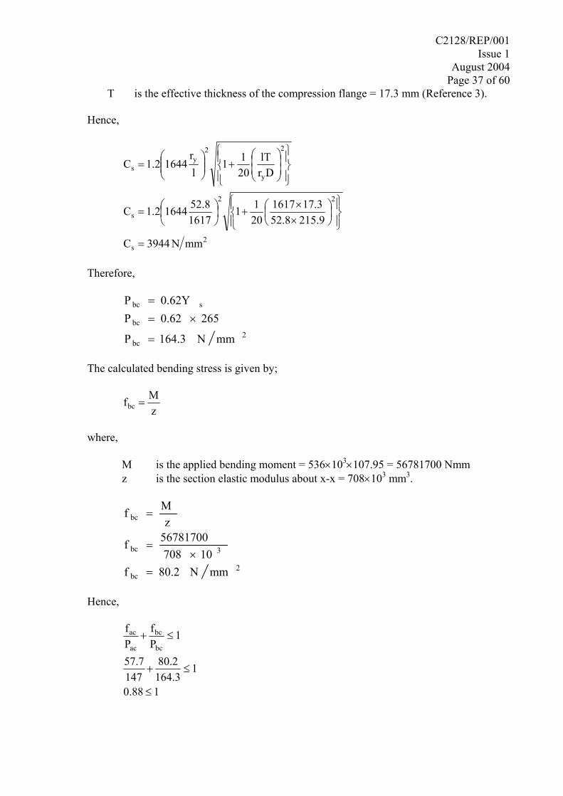
T is the effective thickness of the compression flange = 17.3 mm (Reference 3).
Hence,
2s
22
s
2
y
2y
s
mmN3944C
215.952.817.31617
2011
161752.816441.2C
DrlT
2011
lr
16441.2C
=
⎪⎭
⎪⎬⎫
⎪⎩
⎪⎨⎧
⎟⎠⎞
⎜⎝⎛
××
+⎟⎠⎞
⎜⎝⎛=
⎪⎭
⎪⎬⎫
⎪⎩
⎪⎨⎧
⎟⎟⎠
⎞⎜⎜⎝
⎛+⎟⎟
⎠
⎞⎜⎜⎝
⎛=
Therefore,
2
bc
bc
sbc
mmN164.3P
2650.62P0.62YP
=
×==
The calculated bending stress is given by;
zMfbc =
where,
M is the applied bending moment = 536×103×107.95 = 56781700 Nmm z is the section elastic modulus about x-x = 708×103 mm3.
2bc
3bc
bc
mmN80.2f10708
56781700f
zMf
=×
=
=
Hence,
188.0
1164.380.2
14757.7
1Pf
Pf
bc
bc
ac
ac
≤
≤+
≤+
C2128/REP/001 Issue 1
August 2004 Page 38 of 60
3.0 PROPOSED CONCEPT SELECTION 3.1 FRAME DESIGN SELECTION
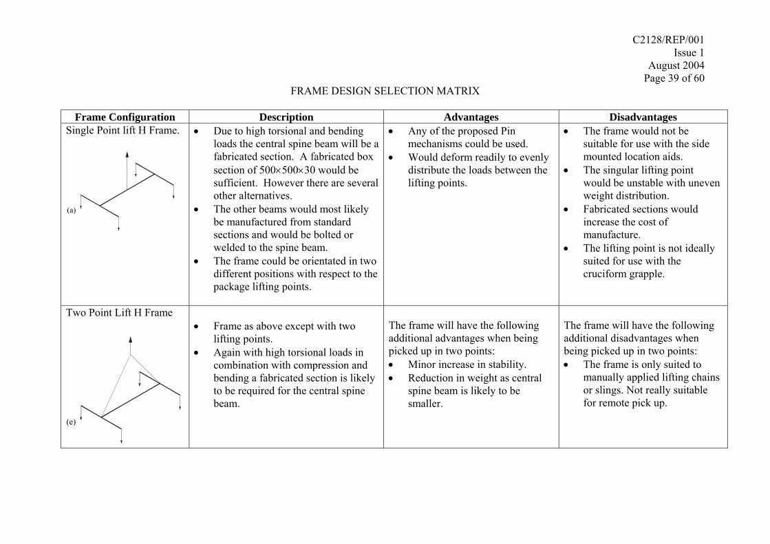
The frame concept designs are reviewed below in a selection matrix. The advantages and disadvantages of each concept are discussed in relation to the design specifications and the following additional considerations:
Stability – especially with eccentric centre of gravity Ease of Manufacture/assembly. Ease of use. Cost Adaptability – ability to be modified or resized for different SWTC’s (Standardisation). – ability to be modified to accept different crane manipulators. Weight/size Transportation/Storage Reliability
C2128/REP/001 Issue 1
August 2004 Page 39 of 60
FRAME DESIGN SELECTION MATRIX
Frame Configuration Description Advantages Disadvantages Single Point lift H Frame.
(a)
• Due to high torsional and bending loads the central spine beam will be a fabricated section. A fabricated box section of 500×500×30 would be sufficient. However there are several other alternatives.
• The other beams would most likely be manufactured from standard sections and would be bolted or welded to the spine beam.
• The frame could be orientated in two different positions with respect to the package lifting points.
• Any of the proposed Pin mechanisms could be used.
• Would deform readily to evenly distribute the loads between the lifting points.
• The frame would not be suitable for use with the side mounted location aids.
• The singular lifting point would be unstable with uneven weight distribution.
• Fabricated sections would increase the cost of manufacture.
• The lifting point is not ideally suited for use with the cruciform grapple.
Two Point Lift H Frame
(e)
• Frame as above except with two
lifting points. • Again with high torsional loads in
combination with compression and bending a fabricated section is likely to be required for the central spine beam.
The frame will have the following additional advantages when being picked up in two points: • Minor increase in stability. • Reduction in weight as central
spine beam is likely to be smaller.
The frame will have the following additional disadvantages when being picked up in two points: • The frame is only suited to
manually applied lifting chains or slings. Not really suitable for remote pick up.
C2128/REP/001 Issue 1
August 2004 Page 40 of 60
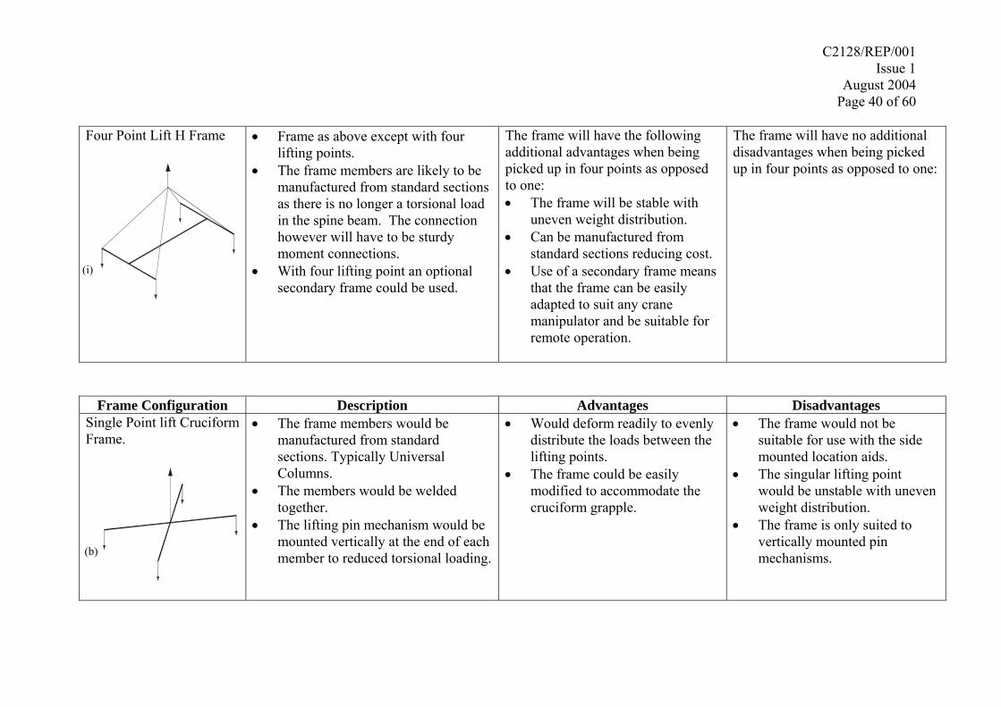
Four Point Lift H Frame
(i)
• Frame as above except with four lifting points.
• The frame members are likely to be manufactured from standard sections as there is no longer a torsional load in the spine beam. The connection however will have to be sturdy moment connections.
• With four lifting point an optional secondary frame could be used.
The frame will have the following additional advantages when being picked up in four points as opposed to one: • The frame will be stable with
uneven weight distribution. • Can be manufactured from
standard sections reducing cost. • Use of a secondary frame means
that the frame can be easily adapted to suit any crane manipulator and be suitable for remote operation.
The frame will have no additional disadvantages when being picked up in four points as opposed to one:
Frame Configuration Description Advantages Disadvantages Single Point lift Cruciform Frame.
(b)
• The frame members would be manufactured from standard sections. Typically Universal Columns.
• The members would be welded together.
• The lifting pin mechanism would be mounted vertically at the end of each member to reduced torsional loading.
• Would deform readily to evenly distribute the loads between the lifting points.
• The frame could be easily modified to accommodate the cruciform grapple.
• The frame would not be suitable for use with the side mounted location aids.
• The singular lifting point would be unstable with uneven weight distribution.
• The frame is only suited to vertically mounted pin mechanisms.
C2128/REP/001 Issue 1
August 2004 Page 41 of 60
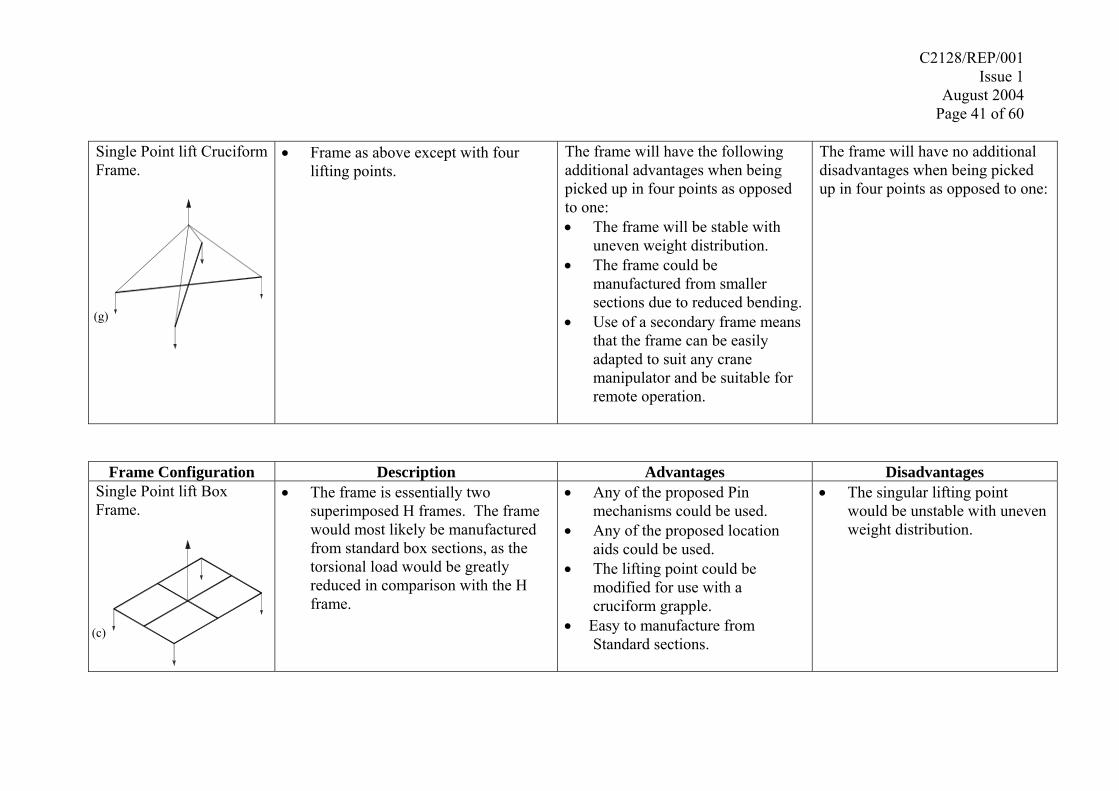
Single Point lift Cruciform Frame.
(g)
• Frame as above except with four lifting points.
The frame will have the following additional advantages when being picked up in four points as opposed to one: • The frame will be stable with
uneven weight distribution. • The frame could be
manufactured from smaller sections due to reduced bending.
• Use of a secondary frame means that the frame can be easily adapted to suit any crane manipulator and be suitable for remote operation.
The frame will have no additional disadvantages when being picked up in four points as opposed to one:
Frame Configuration Description Advantages Disadvantages Single Point lift Box Frame.
(c)
• The frame is essentially two superimposed H frames. The frame would most likely be manufactured from standard box sections, as the torsional load would be greatly reduced in comparison with the H frame.
• Any of the proposed Pin mechanisms could be used.
• Any of the proposed location aids could be used.
• The lifting point could be modified for use with a cruciform grapple.
• Easy to manufacture from Standard sections.
• The singular lifting point would be unstable with uneven weight distribution.
C2128/REP/001 Issue 1
August 2004 Page 42 of 60
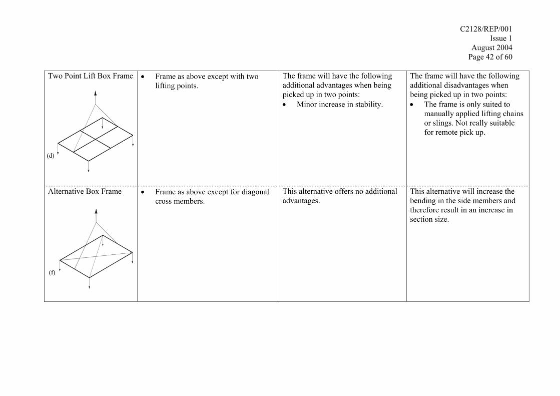
Two Point Lift Box Frame
(d)
• Frame as above except with two lifting points.
The frame will have the following additional advantages when being picked up in two points: • Minor increase in stability.
The frame will have the following additional disadvantages when being picked up in two points: • The frame is only suited to
manually applied lifting chains or slings. Not really suitable for remote pick up.
Alternative Box Frame
(f)
• Frame as above except for diagonal cross members.
This alternative offers no additional advantages.
This alternative will increase the bending in the side members and therefore result in an increase in section size.
C2128/REP/001 Issue 1
August 2004 Page 43 of 60
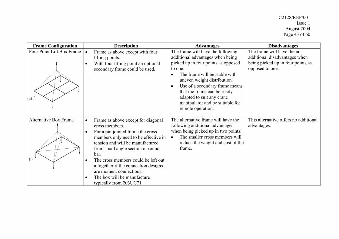
Frame Configuration Description Advantages Disadvantages
Four Point Lift Box Frame
(h)
• Frame as above except with four lifting points.
• With four lifting point an optional secondary frame could be used.
The frame will have the following additional advantages when being picked up in four points as opposed to one: • The frame will be stable with
uneven weight distribution. • Use of a secondary frame means
that the frame can be easily adapted to suit any crane manipulator and be suitable for remote operation.
The frame will have the no additional disadvantages when being picked up in four points as opposed to one:
Alternative Box Frame
(j)
• Frame as above except for diagonal cross members.
• For a pin jointed frame the cross members only need to be effective in tension and will be manufactured from small angle section or round bar.
• The cross members could be left out altogether if the connection designs are moment connections.
• The box will be manufacture typically from 203UC71.
The alternative frame will have the following additional advantages when being picked up in two points: • The smaller cross members will
reduce the weight and cost of the frame.
This alternative offers no additional advantages.
C2128/REP/001 Issue 1
August 2004 Page 44 of 60
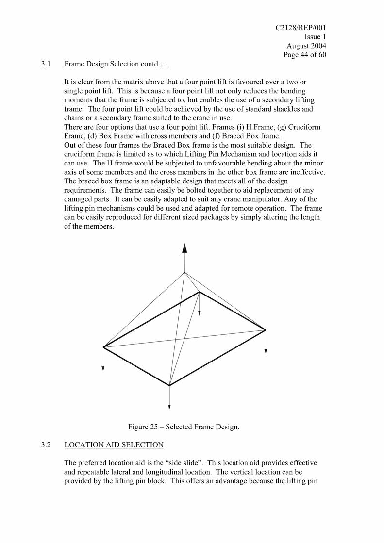
3.1 Frame Design Selection contd.…
It is clear from the matrix above that a four point lift is favoured over a two or single point lift. This is because a four point lift not only reduces the bending moments that the frame is subjected to, but enables the use of a secondary lifting frame. The four point lift could be achieved by the use of standard shackles and chains or a secondary frame suited to the crane in use. There are four options that use a four point lift. Frames (i) H Frame, (g) Cruciform Frame, (d) Box Frame with cross members and (f) Braced Box frame. Out of these four frames the Braced Box frame is the most suitable design. The cruciform frame is limited as to which Lifting Pin Mechanism and location aids it can use. The H frame would be subjected to unfavourable bending about the minor axis of some members and the cross members in the other box frame are ineffective. The braced box frame is an adaptable design that meets all of the design requirements. The frame can easily be bolted together to aid replacement of any damaged parts. It can be easily adapted to suit any crane manipulator. Any of the lifting pin mechanisms could be used and adapted for remote operation. The frame can be easily reproduced for different sized packages by simply altering the length of the members.
Figure 25 – Selected Frame Design.
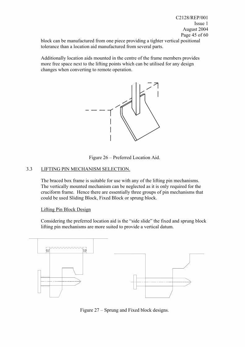
3.2 LOCATION AID SELECTION
The preferred location aid is the “side slide”. This location aid provides effective and repeatable lateral and longitudinal location. The vertical location can be provided by the lifting pin block. This offers an advantage because the lifting pin
C2128/REP/001 Issue 1
August 2004 Page 45 of 60
block can be manufactured from one piece providing a tighter vertical positional tolerance than a location aid manufactured from several parts.
Additionally location aids mounted in the centre of the frame members provides more free space next to the lifting points which can be utilised for any design changes when converting to remote operation.
Figure 26 – Preferred Location Aid.
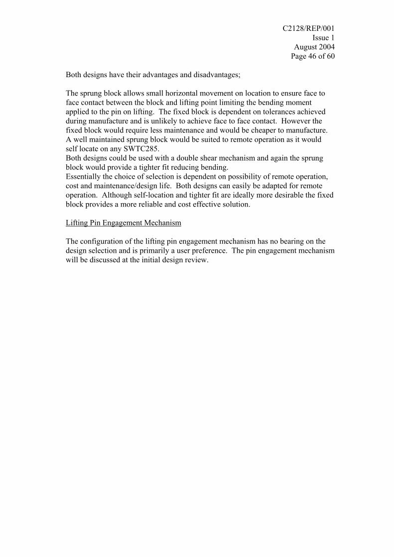
3.3 LIFTING PIN MECHANISM SELECTION.
The braced box frame is suitable for use with any of the lifting pin mechanisms. The vertically mounted mechanism can be neglected as it is only required for the cruciform frame. Hence there are essentially three groups of pin mechanisms that could be used Sliding Block, Fixed Block or sprung block. Lifting Pin Block Design
Considering the preferred location aid is the “side slide” the fixed and sprung block lifting pin mechanisms are more suited to provide a vertical datum.
Figure 27 – Sprung and Fixed block designs.
C2128/REP/001 Issue 1
August 2004 Page 46 of 60
Both designs have their advantages and disadvantages; The sprung block allows small horizontal movement on location to ensure face to face contact between the block and lifting point limiting the bending moment applied to the pin on lifting. The fixed block is dependent on tolerances achieved during manufacture and is unlikely to achieve face to face contact. However the fixed block would require less maintenance and would be cheaper to manufacture. A well maintained sprung block would be suited to remote operation as it would self locate on any SWTC285. Both designs could be used with a double shear mechanism and again the sprung block would provide a tighter fit reducing bending. Essentially the choice of selection is dependent on possibility of remote operation, cost and maintenance/design life. Both designs can easily be adapted for remote operation. Although self-location and tighter fit are ideally more desirable the fixed block provides a more reliable and cost effective solution. Lifting Pin Engagement Mechanism
The configuration of the lifting pin engagement mechanism has no bearing on the design selection and is primarily a user preference. The pin engagement mechanism will be discussed at the initial design review.
C2128/REP/001 Issue 1
August 2004 Page 47 of 60
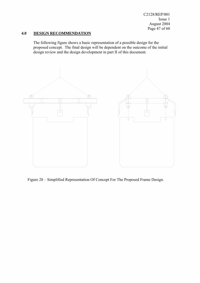
4.0 DESIGN RECOMMENDATION The following figure shows a basic representation of a possible design for the proposed concept. The final design will be dependent on the outcome of the initial design review and the design development in part II of this document.
Figure 28 – Simplified Representation Of Concept For The Proposed Frame Design.