Embed Size (px)
Citation preview
Design Space Exploration in an FPGA-BasedSoftware Defined Radio
Matthieu Gautier, Ganda Stephane Ouedraogo and Olivier SentieysINRIA, University of Rennes, IRISA, France
6 rue Kerampont, 22300 Lannion, France
[email protected], [email protected], [email protected]
Abstract— The FPGA (Field Programmable Gate Array) tech-nology is expected to play a key role in the development ofSoftware Defined Radio (SDR) platforms. To this aim, leveragingthe nascent High-Level Synthesis (HLS) tools, a design flowfrom high-level specifications to Register-Transfer Level (RTL)description can be thought. Based on such a flow, this paperdescribes the Design Space Exploration (DSE) that can beachieved using loop optimizations. The mainstream objective isto demonstrate the compile-time flexibility of an architecturewhen associated with a reconfigurable platform. Throughout bothIEEE 802.15.4 and IEEE 802.11g waveform examples, we showhow the FPGA resources can be tuned according to a targetedthroughput.
Keywords— Software Defined Radio (SDR), Design SpaceExploration, Field Programmable Gate Array (FPGA), High-Level Synthesis (HLS).
I. INTRODUCTION
Software Defined Radio (SDR) is an emergent technology
that aims at being the hardware support of future smart radios
that have the capability to change their configuration according
to the environmental conditions [1]. The main feature of
an SDR is its flexibility and fast prototyping capabilities
from an high-level description. Thus, one of the mainstream
approaches to specify an SDR platform consists in implement-
ing the processing on Digital Signal Processors (DSP) [2].
However, DSP also suffer from important power consumption
and limited performance as compared to specialized hardware
fabrics. Thus, Field Programmable Gate Array (FPGA) turned
out to be an interesting alternative to DSP. FPGA-based SDR
is an old paradigm [3] offering a good tradeoff between
reconfiguration capability and power consumption.
Our study relies on a novel design flow for the rapid
prototyping of FPGA-based SDR applications [4]. This flow
leverages High-Level Synthesis (HLS) principles and tools
to generate Register-Transfer Level (RTL) description from
high-level specifications. Its entry point is a Domain-Specific
Language (DSL) [5] which partly handles the complexity
of programming an FPGA. It also considers heterogeneous
description of signal processing IPs (Intellectual Properties)
and integrates SDR features.
Based on this flow, this paper addresses the rapid prototyp-
ing of various designs of a given waveform, an architecture
exploration is performed showing the flexibility feature of such
a design flow. Indeed, HLS tools and their associated compilers
give a special emphasis to the timing, area or throughput
constraints and make it easy to explore a set of solution via
Design Space Exploration (DSE) [6][7] considering a given
architecture.
The main contributions of this article are:
- To insert compile-time flexibility feature in the design
flow,
- To analyse throughput/area tradeoff using HLS tools,
- To explore different designs for two useful standards:
IEEE 802.15.4 and IEEE 802.11g.
The paper is organized as follows. A discussion over related
works is given in Section II. The FPGA-based SDR design
flow is introduced in Section III. Section IV details the DSE
based on the throughput/area tradeoff and the implementation
of the flexibility capabilities in the design flow. A DSE
validation is given in Section V for architectures based on
IEEE 802.15.4 and IEEE 802.11g standards. Finally, conclu-
sions and perspectives are drawn in Section VI.
II. RELATED WORKS
Several proposals attempted to meet the flexibility require-
ments of an SDR by using software-based approaches. Indeed,
software gives an abstraction level that enables more con-
trol over the hardware designing flow. Two complementary
approaches have been proposed namely, the SDR-specific
languages to design the waveform [8][9][10] and the SDR
middleware to provide the building environment [11][12].
They both take advantage of the abstraction level given by
the software.
Our proposal aims at keeping a higher level of specification
while addressing FPGA-based SDR. To this end, HLS turns
out to be a good candidate to achieve such a high level
of abstraction and a specific language has been proposed to
describe the waveform. Just like in these related works, the
compile-time flexibility is achieved by the fast prototyping
capability which is enabled in our proposal by the HLS.
III. INTRODUCTION TO FPGA-SDR DESIGN FLOW
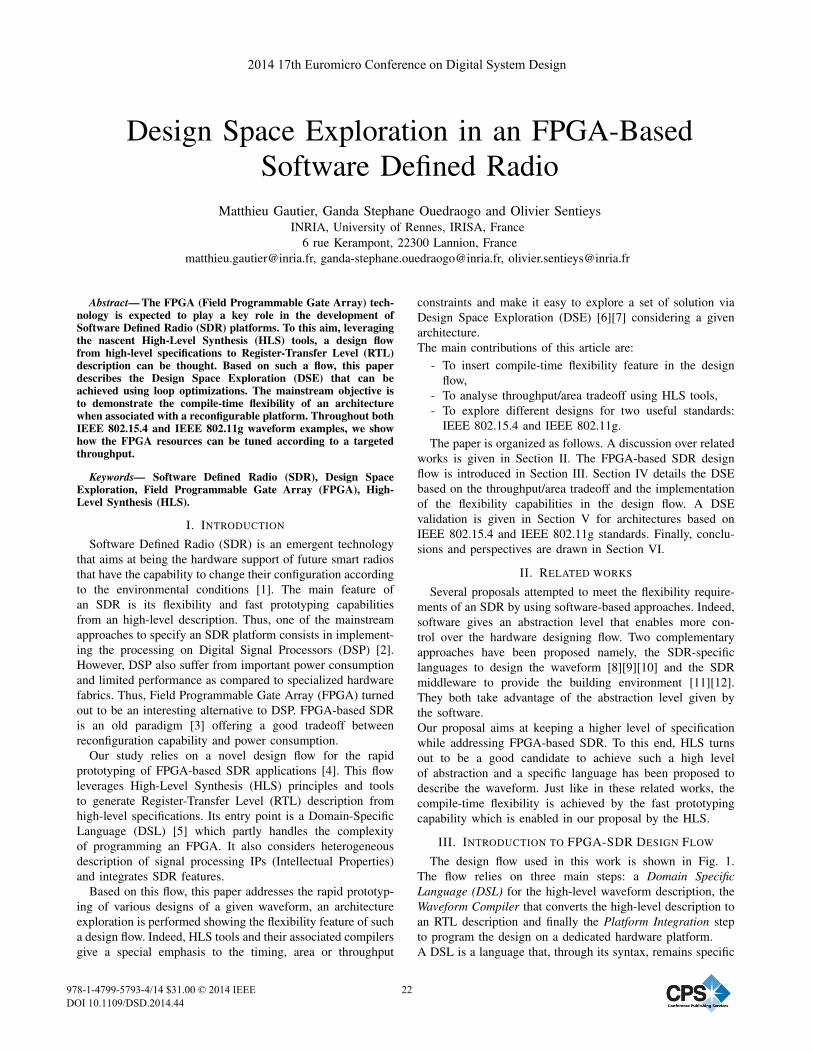
The design flow used in this work is shown in Fig. 1.
The flow relies on three main steps: a Domain SpecificLanguage (DSL) for the high-level waveform description, the
Waveform Compiler that converts the high-level description to
an RTL description and finally the Platform Integration step
to program the design on a dedicated hardware platform.
A DSL is a language that, through its syntax, remains specific
2014 17th Euromicro Conference on Digital System Design
978-1-4799-5793-4/14 $31.00 © 2014 IEEE
DOI 10.1109/DSD.2014.44
22
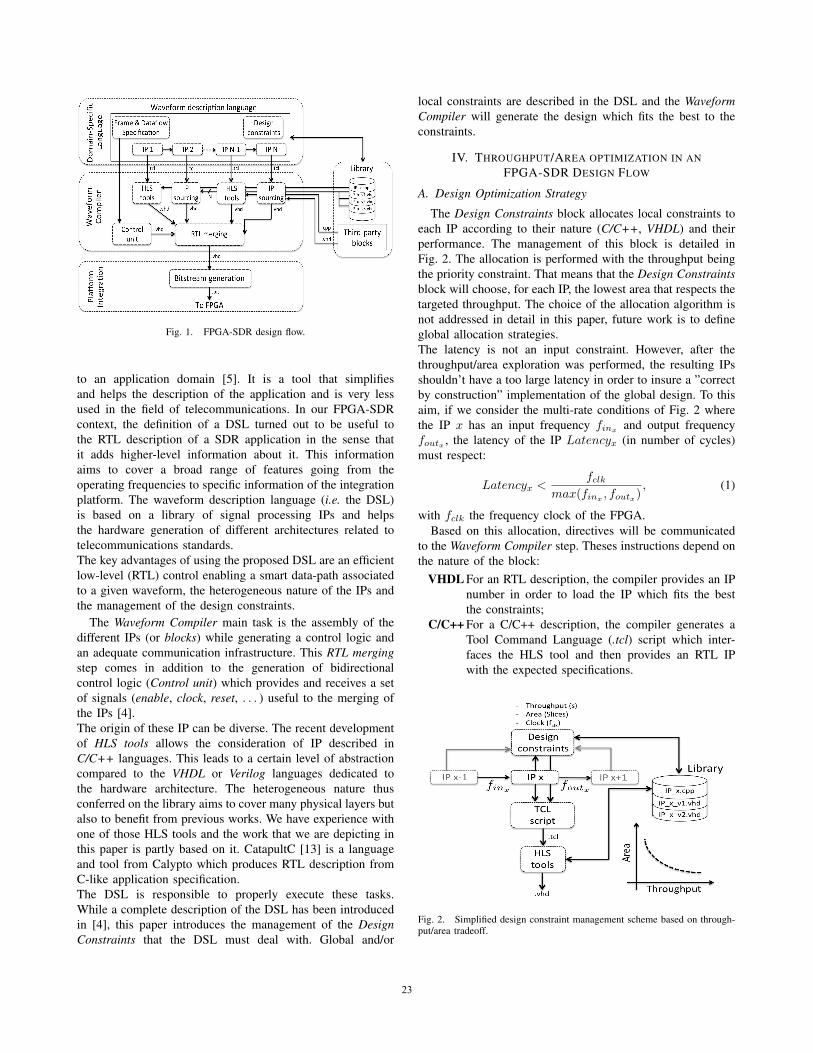
Fig. 1. FPGA-SDR design flow.
to an application domain [5]. It is a tool that simplifies
and helps the description of the application and is very less
used in the field of telecommunications. In our FPGA-SDR
context, the definition of a DSL turned out to be useful to
the RTL description of a SDR application in the sense that
it adds higher-level information about it. This information
aims to cover a broad range of features going from the
operating frequencies to specific information of the integration
platform. The waveform description language (i.e. the DSL)
is based on a library of signal processing IPs and helps
the hardware generation of different architectures related to
telecommunications standards.
The key advantages of using the proposed DSL are an efficient
low-level (RTL) control enabling a smart data-path associated
to a given waveform, the heterogeneous nature of the IPs and
the management of the design constraints.
The Waveform Compiler main task is the assembly of the
different IPs (or blocks) while generating a control logic and
an adequate communication infrastructure. This RTL mergingstep comes in addition to the generation of bidirectional
control logic (Control unit) which provides and receives a set
of signals (enable, clock, reset, . . . ) useful to the merging of
the IPs [4].
The origin of these IP can be diverse. The recent development
of HLS tools allows the consideration of IP described in
C/C++ languages. This leads to a certain level of abstraction
compared to the VHDL or Verilog languages dedicated to
the hardware architecture. The heterogeneous nature thus
conferred on the library aims to cover many physical layers but
also to benefit from previous works. We have experience with
one of those HLS tools and the work that we are depicting in
this paper is partly based on it. CatapultC [13] is a language
and tool from Calypto which produces RTL description from
C-like application specification.
The DSL is responsible to properly execute these tasks.
While a complete description of the DSL has been introduced
in [4], this paper introduces the management of the DesignConstraints that the DSL must deal with. Global and/or
local constraints are described in the DSL and the WaveformCompiler will generate the design which fits the best to the
constraints.
IV. THROUGHPUT/AREA OPTIMIZATION IN AN
FPGA-SDR DESIGN FLOW
A. Design Optimization Strategy
The Design Constraints block allocates local constraints to
each IP according to their nature (C/C++, VHDL) and their
performance. The management of this block is detailed in
Fig. 2. The allocation is performed with the throughput being
the priority constraint. That means that the Design Constraintsblock will choose, for each IP, the lowest area that respects the
targeted throughput. The choice of the allocation algorithm is
not addressed in detail in this paper, future work is to define
global allocation strategies.
The latency is not an input constraint. However, after the
throughput/area exploration was performed, the resulting IPs
shouldn’t have a too large latency in order to insure a ”correct
by construction” implementation of the global design. To this
aim, if we consider the multi-rate conditions of Fig. 2 where
the IP x has an input frequency finx and output frequency
foutx , the latency of the IP Latencyx (in number of cycles)
must respect:
Latencyx <fclk
max(finx , foutx), (1)
with fclk the frequency clock of the FPGA.
Based on this allocation, directives will be communicated
to the Waveform Compiler step. Theses instructions depend on
the nature of the block:
VHDL For an RTL description, the compiler provides an IP
number in order to load the IP which fits the best
the constraints;
C/C++ For a C/C++ description, the compiler generates a
Tool Command Language (.tcl) script which inter-
faces the HLS tool and then provides an RTL IP
with the expected specifications.
Fig. 2. Simplified design constraint management scheme based on through-put/area tradeoff.
23
The Waveform Compiler of the DSL generates .tcl scripts to
control the CatapultC software. Using .tcl will help for rapid
prototyping with the automation of the transformation.
B. Processing Block Generation
The objective is to study the effect of the optimization
tools provided by CatapultC. To illustrate and test the RTL
generation of a processing block, we use the correlation bench
function (named CorrBench) of an IEEE 802.15.4 Zigbee
receiver. The full receiver is detailed in Fig. 7. This CorrBenchfunction is a set of 16 FIR (Finite Impulse Response) filters
with 16 taps, each filter performing the correlation between
the received data and a code. A filter consists of 2 loops:
Shift that shifts the data of a FIFO register and buffers the
new input data,
MAC that performs a multiplication and accumulation to
compute the output of the filter.
This function is optimized using the CatapultC tools and the
resource estimation of the resulting RTL designs are estimated
using both CatapultC area estimation and ISE complexity
estimation.
Design Exploration using HLS Tool
Several optimizations are made available on a typical HLS
tool [13]. These tools make it possible to optimize the design
at the area or throughput level. Two of the design optimizations
from CatapultC that we use are loop pipelining and loop
unrolling. Loop pipelining provides a way to increase the
throughput of a loop (or decreasing its overall latency) by
initiating the (i+1)-th iteration of the loop before the i-
th iteration has completed. The number of cycles between
iterations of the loop is called the initiation interval (II). The
less the II is the more the pipeline is. Loop unrolling reduces
the total loop iterations by duplicating (with a factor U) the
loop bodies. The number of loop iterations is then reduced
but care must be taken to the data dependencies when using
this technique. Loop unrolling impacts the design latency and
consequently the throughput.
Area Estimation using HLS Tool
The objective of the area estimation is to check the influence
of loop optimization parameters. This will help the allocation
algorithm to set these parameters according to the design
constraints.
Fig. 3 gives the area score provided by CataplutC versus the
throughput for different designs. The throughput refers to how
often, in clock cycles, a block can complete its processing [13].
The different designs are obtained by loop pipelining and loop
unrolling the filters of the CorrBench function. The results
show the throughput/area tradeoff that could be achieved
using the HLS tools. Without optimization, the throughput
is 32 cycles (because of the 2 loops with 16 iterations of
the CorrBench function). By using loop optimizations, the
throughput in cycles can decrease (thus increase in frequency)
down to 2 cycles while increasing the area by a factor of 1.6.
Going into details, Fig. 3 shows that, for a given II of the
Fig. 3. Coarse estimation: throughput/area tradeoff of the CorrBench block.
pipelining, the more unrolled the loop is, the higher the area
is and the lower the throughput is. It is possible to see from
these curves that low throughput in cycles (high in frequency)
is achieved when the design is pipelined to a maximum (II=1).
These results provide a coarse estimation of the design com-
plexity according to different optimization techniques.
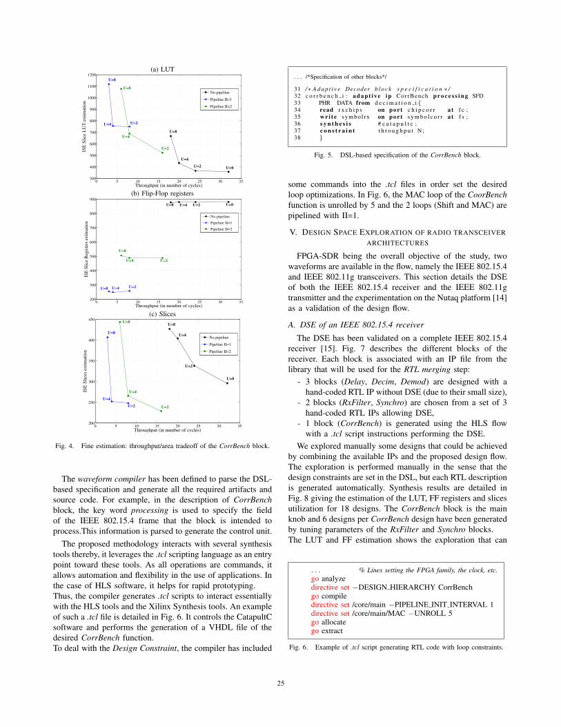
Resource Estimation using Synthesis Tool
The fine estimation is computed using ISE synthesis tool
targeting a Virtex 6 FPGA. Synthesis results are detailed in
Fig. 4 giving the estimation of the Look-Up Table (LUT), Flip-
Flop (FF) registers and slices utilization. Results show that the
number of LUT increases with the pipeline and the unrolling
factor (U). Pipelining the design increases the number of FF
registers while the loop unrolling has no influence on it. The
link between the loop optimizations and the number of slices
is more complex to draw. Indeed, the Virtex 6 slices are
composed of 4 LUT and 8 FF registers and the ISE synthesis
optimizes the slices interconnections and their occupations.
It is possible to note that the LUT estimation follows the
CatapultC area estimation as a reference.
C. Implementation in the FPGA-SDR design flow
The proposed design exploration is integrated in the pro-
posed design flow in order to achieve a compile-time recon-
figuration of the waveforms. To this end, willing to include
flexibility requirements, a flexible block is declared with the
key word adaptive in the DSL source code. This declaration
highlights in the description the flexible nature of the block and
enables compile-time flexibility through the DSE feature that
can be afforded through the HLS tools as previously shown.
DSE allows to optimize away a given architecture depending
on some throughput, area or energy constraints.The key word
constraint is used to set the constraints.
As an illustration, Fig. 5 introduces the DSL specification of
the CorrBench block, it is declared adaptive with a throughput
constraint. Thus, different solutions of the block could be
quickly explored by tuning the constraints.
24
(a) LUT
0 5 10 15 20 25 30 35300
400
500
600
700
800
900
1000
1100
1200
Throughput (in number of cycles)
ISE
Slic
e L
UT
est
imat
ion
No pipeline
Pipeline II=1
Pipeline II=2
U=8
U=4
U=8
U=4
U=2
U=8
U=2
U=4
U=2
U=0
(b) Flip-Flop registers
0 5 10 15 20 25 30 35200
300
400
500
600
700
800
900
Throughput (in number of cycles)
ISE
Slic
e R
egis
ters
est
imat
ion
No pipeline
Pipeline II=1
Pipeline II=2
U=4
U=4
U=8
U=8 U=2
U=8 U=4 U=2 U=0
U=2
(c) Slices
0 5 10 15 20 25 30 35200
250
300
350
400
450
Throughput (in number of cycles)
ISE
Slic
es e
stim
atio
n
No pipeline
Pipeline II=1
Pipeline II=2
U=8
U=4
U=4
U=8
U=0
U=2
U=2
U=8
U=2
U=4
Fig. 4. Fine estimation: throughput/area tradeoff of the CorrBench block.
The waveform compiler has been defined to parse the DSL-
based specification and generate all the required artifacts and
source code. For example, in the description of CorrBenchblock, the key word processing is used to specify the field
of the IEEE 802.15.4 frame that the block is intended to
process.This information is parsed to generate the control unit.
The proposed methodology interacts with several synthesis
tools thereby, it leverages the .tcl scripting language as an entry
point toward these tools. As all operations are commands, it
allows automation and flexibility in the use of applications. In
the case of HLS software, it helps for rapid prototyping.
Thus, the compiler generates .tcl scripts to interact essentially
with the HLS tools and the Xilinx Synthesis tools. An example
of such a .tcl file is detailed in Fig. 6. It controls the CatapultC
software and performs the generation of a VHDL file of the
desired CorrBench function.
To deal with the Design Constraint, the compiler has included
. . . /*Specification of other blocks*/
31 /∗ A d a p t i v e Decoder b l o c k s p e c i f i c a t i o n ∗ /32 c o r r b e n c h i : a d a p t i v e i p CorrBench p r o c e s s i n g SFD33 PHR DATA from d e c i m a t i o n i{34 read r x c h i p s on port c h i p c o r r at f c ;35 w r i t e symbol rx on port s y m b o l c o r r at f s ;36 s y n t h e s i s # c a t a p u l t c ;37 c o n s t r a i n t t h r o u g h p u t N;38 }
Fig. 5. DSL-based specification of the CorrBench block.
some commands into the .tcl files in order set the desired
loop optimizations. In Fig. 6, the MAC loop of the CoorBenchfunction is unrolled by 5 and the 2 loops (Shift and MAC) are
pipelined with II=1.
V. DESIGN SPACE EXPLORATION OF RADIO TRANSCEIVER
ARCHITECTURES
FPGA-SDR being the overall objective of the study, two
waveforms are available in the flow, namely the IEEE 802.15.4
and IEEE 802.11g transceivers. This section details the DSE
of both the IEEE 802.15.4 receiver and the IEEE 802.11g
transmitter and the experimentation on the Nutaq platform [14]
as a validation of the design flow.
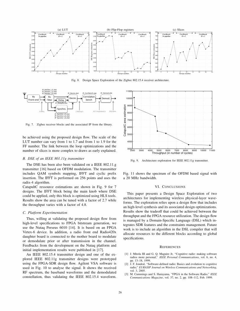
A. DSE of an IEEE 802.15.4 receiver
The DSE has been validated on a complete IEEE 802.15.4
receiver [15]. Fig. 7 describes the different blocks of the
receiver. Each block is associated with an IP file from the
library that will be used for the RTL merging step:
- 3 blocks (Delay, Decim, Demod) are designed with a
hand-coded RTL IP without DSE (due to their small size),
- 2 blocks (RxFilter, Synchro) are chosen from a set of 3
hand-coded RTL IPs allowing DSE,
- 1 block (CorrBench) is generated using the HLS flow
with a .tcl script instructions performing the DSE.
We explored manually some designs that could be achieved
by combining the available IPs and the proposed design flow.
The exploration is performed manually in the sense that the
design constraints are set in the DSL, but each RTL description
is generated automatically. Synthesis results are detailed in
Fig. 8 giving the estimation of the LUT, FF registers and slices
utilization for 18 designs. The CorrBench block is the main
knob and 6 designs per CorrBench design have been generated
by tuning parameters of the RxFilter and Synchro blocks.
The LUT and FF estimation shows the exploration that can
. . . % Lines setting the FPGA family, the clock, etc.go analyzedirective set −DESIGN HIERARCHY CorrBenchgo compiledirective set /core/main −PIPELINE INIT INTERVAL 1directive set /core/main/MAC −UNROLL 5go allocatego extract
Fig. 6. Example of .tcl script generating RTL code with loop constraints.
25
(a) LUT (b) Flip-Flop registers (c) Slices
2 4 6 8 10 12 14 16 181300
1400
1500
1600
1700
1800
1900
2000
2100
2200
2300
Design number
ISE
LU
T e
stim
atio
n
CorrBenchII = 2
CorrBenchII = 1
CorrBench No pipeline
2 4 6 8 10 12 14 16 18900
1000
1100
1200
1300
1400
1500
1600
1700
1800
Design number
ISE
Reg
iste
r es
timat
ion
CorrBenchII = 2
CorrBenchII = 1
CorrBench No pipeline
2 4 6 8 10 12 14 16 18600
620
640
660
680
700
720
740
760
780
800
Design number
ISE
Slic
e es
timat
ion
CorrBench No pipeline
CorrBenchII = 2
CorrBenchII = 1
Fig. 8. Design Space Exploration of the Zigbee 802.15.4 receiver architecture.
�����������
� �����������������
��������� ������
�������
� � � � �
�����������
�����������������
���������
� ������������������ � ������� � �����
� ������!������""�
� ������������������ ������������������ ����������� ����� � ������������� ������������
� ��������������
#�$%&� ��$���"'(� )��*�+(�����('(� �*,�+��(
Fig. 7. Zigbee receiver blocks and the associated IP from the library.
be achieved using the proposed design flow. The scale of the
LUT number can vary from 1 to 1.7 and from 1 to 1.9 for the
FF number. The link between the loop optimizations and the
number of slices is more complex to draws as early explained.
B. DSE of an IEEE 801.11g transmitter
The DSE has been also been validated on a IEEE 802.11.g
transmitter [16] based on OFDM modulation. The transmitter
includes QAM symbols mapping, IFFT and cyclic prefix
insertion. The IFFT is performed on 256 points and uses the
radix-4 algorithm.
CatapultC ressource estimations are shown in Fig. 9 for 7
designs. The IFFT block being the main knob where DSE
could be applied, only this block is optimized using HLS tools.
Results show the area can be tuned with a factor of 2.7 while
the throughput varies with a factor of 4.8.
C. Platform Experimentation
Thus, willing at validating the proposed design flow from
high-level specifications to FPGA bitstream generation, we
use the Nutaq Perseus 6010 [14]. It is based on an FPGA
Virtex-6 device. In addition, a radio front end Radio420x
daughter board is connected to the mother board to modulate
or demodulate prior or after transmission in the channel.
Feedbacks from the development on the Nutaq platform and
initial implementation results were published in [17].
An IEEE 802.15.4 transmitter design and one of the ex-
plored IEEE 802.11g transmitter designs were prototyped
using the FPGA-SDR design flow. Agilent VSA software is
used in Fig. 10 to analyse the signal. It shows the received
RF spectrum, the baseband waveforms and the demodulated
constellation, thus validating the IEEE 802.15.4 waveform.
2000 3000 4000 5000 6000 7000 8000 9000 10000 110003000
4000
5000
6000
7000
8000
9000
10000
11000
Throughput (in number of cycles)
Cat
apul
tC a
rea
estim
atio
n
Fig. 9. Architecture exploration for IEEE 802.11g transmitter.
Fig. 11 shows the spectrum of the OFDM based signal with
a 20 MHz bandwidth.
VI. CONCLUSIONS
This paper presents a Design Space Exploration of two
architectures for implementing wireless physical-layer wave-
forms. The exploration relies upon a design flow that includes
an high-level synthesis and its associated design optimizations.
Results show the tradeoff that could be achieved between the
throughput and the FPGA resource utilization. The design flow
is managed by a Domain-Specific Language (DSL) which in-
tegrates SDR features and the constraints management. Future
work is to include an algorithm in the DSL compiler that will
allocate resources to the different blocks according to global
specifications.
REFERENCES
[1] J. Mitola III and G. Q. Maguire Jr, “Cognitive radio: making softwareradios more personal,” IEEE Personal Communications, vol. 6, no. 4,pp. 13–18, 1999.
[2] J. F. Jondral, “Software-defined radio: Basics and evolution to cognitiveradio,” EURASIP Journal on Wireless Communications and Networking,vol. 3, 2005.
[3] M. Cummings and S. Haruyama, “FPGA in the Software Radio,” IEEECommunications Magazine, vol. 37, no. 2, pp. 108–112, Feb. 1999.
26
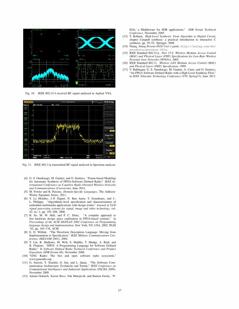
Fig. 10. IEEE 802.15.4 received RF signal analysed in Agilent VSA.
Fig. 11. IEEE 802.11g transmitted RF signal analysed in Spectrum analyser.
[4] G. S. Ouedraogo, M. Gautier, and O. Sentieys, “Frame-based Modelingfor Automatic Synthesis of FPGA-Software Defined Radio,” IEEE In-ternational Conference on Cognitive Radio Oriented Wireless Networksand Communications (Crowncom), June 2014.
[5] M. Fowler and R. Parsons, Domain-Specific Languages, The Addison-Wisley Signature Series, 2011.
[6] Y. Le Moullec, J.-P. Diguet, N. Ben Amor, T. Gourdeaux, and J.-L. Philippe, “Algorithmic-level specification and characterization ofembedded multimedia applications with design trotter,” Journal of VLSIsignal processing systems for signal, image and video technology, vol.42, no. 2, pp. 185–208, 2006.
[7] B. So, M. W. Hall, and P. C. Diniz, “A compiler approach tofast hardware design space exploration in FPGA-based systems,” inProceedings of the ACM SIGPLAN 2002 Conference on Programminglanguage design and implementation, New York, NY, USA, 2002, PLDI’02, pp. 165–176, ACM.
[8] E. D. Willink, “The Waveform Description Language: Moving fromImplementation to Specification,” IEEE Military Communications Con-ference (MILCOM 2001), 2004.
[9] Y. Lin, R. Mullenix, M. Woh, S. Mahlke, T. Mudge, A. Reid, andK. Flautner, “SPEX: A Programming Language for Software DefinedRadio,” In Software Defined Radio Technical Conference and ProductExposition (SDR-Forum 06), November 2006.
[10] “GNU Radio: The free and open software radio ecosystem,”www.gnuradio.org.
[11] G. Jianxin, Y. Xiaohui, G. Jun, and L. Quan, “The Software Com-munication Architecture: Evolutions and Trends,” IEEE Conference onComputational Intelligence and Industrial Applications (PACIIA 2009),November 2009.
[12] Antoni Gelonch, Xavier Revs, Vuk Marojevik, and Ramon Ferrus, “P-
HAL: a Middleware for SDR applications,” SDR Forum TechnicalConference, November 2005.
[13] T. Bollaert, High-Level Synthesis: From Algorithm to Digital Circuit,chapter Catapult synthesis: a practical introduction to interactive Csynthesis, pp. 29–52, Springer, 2008.
[14] Nutaq, Nutaq Perseus 601X User’s guide, http://nutaq.com/en/products/perseus-601x.
[15] IEEE Standard 802,15,4, Part 15.4: Wireless Medium Access Control(MAC) and Physical Layer (PHY) Specifications for Low-Rate WirelessPersonal Area Networks (WPANs), 2003.
[16] IEEE Standard 802.11, Wireless LAN Medium Access Control (MAC)and Physical Layer (PHY) Specification, 1999.
[17] V. Bahtnagar, G. S. Ouedraogo, M. Gautier, A. Carer, and O. Sentieys,“An FPGA Software Defined Radio with a High-Level Synthesis Flow,”in IEEE Vehicular Technology Conference (VTC-Spring13), June 2013.
27

![20140918 CloudsNantesAvalon.ppt [Mode de compatibilité]people.rennes.inria.fr/Adrien.Lebre/PUBLIC/Cloud... · • Expressiveness simplicity • Application portability • Resource](https://img.pdfslide.net/doc/110x75/5f282967de10112bf8053bab/20140918-mode-de-compatibilitpeoplerennesinriafradrienlebrepubliccloud.jpg)