Embed Size (px)
Citation preview

DESIGN STANDARDS
FOR CONFINED
FEEDING FACILITIES
Kansas Department of Health & Environment
Bureau of Water
Livestock Waste Management Section
1000 SW Jackson, Suite 420
Topeka, Kansas 66612-1367
October 20, 2006
Ka
nsa
s D
ep
art
me
nt o
f
He
alth
& E
nvir
on
me
nt

DESIGN STANDARDS FOR CONFINED FEEDING FACILITIES
Table of Contents
Page
I. Introduction 5
II. Plans & Specifications 6
A. General 6
B. Narrative 6
1. Confined Feeding Facility 6
2. Waste Control System Design 6
a. Required Storage Volume Calculations 7
b. Proposed Storage Volume Calculations 7
c. Design Storm Documentation 7
d. Driller’s/Geologist’s Logs 7
3. Operation and Utilization Plan 7
a. Operation and Maintenance 7
b. Manure/Waste Utilization 8
4. Nutrient Management Plan 8
5. Subsurface Monitoring Plan 8
6. Other Information 9
C. Location Map 9
D. Drawings and Details 10
1. Plan Views 10
2. Cross Sections 10
3. Profile Views 10
4. Detailed Views 10
E. Specifications 10
III. Site Location Considerations 11
A. General 11
B. Separation Distances from Habitable Structures 11
1. Habitable Structures 11
2. Separation Distance Determination 11
C. Separation Distances from Property Lines 11
D. Separation Distances from Water Resources 12
1. Surface Water 12
a. All Species Except Swine 12
b. Swine 12
2. Flood Protection 12
3. Groundwater 12
E. Geologic Investigation 13
IV. Minimum Design of Wastewater Control Structures 14
A. General 14
B. Open Channel Structures 14
C. Closed Conduits 14
D. Basins and Structures 15
1. Sedimentation Structures 15

a. General 15
b. Runoff Sediment Basins 15
c. Process Waste Sediment Basins 15
2. Retention Structures 15
a. Hydraulic Volume Calculations 15
b. Biological Volume Calculations 17
Table: Biological Loading for Retention Structures 19
3. Design Criteria for Earthen Structures 20
a. Liners 20
b. Embankment Foundation and Fill 21
c. Emergency Spillways 21
d. Inlets 21
e. Depths 21
4. Non-earthen Structures 22
a. Concrete Tanks 22
b. Metal, Fiberglass, and Other Storage Vessels 22
5. Solid Waste Storage Structures 22
a. General 22
b. Design Criteria 22
6. Hoop Structures 23
7. Other Structures Not Typically Used in Kansas 23
E. Grass Filter Systems 24
1. Sediment Basin 24
2. Flow Distribution System 24
3. Grass Filter Area 24
F. Livestock Truck/Trailer Washes 25
1. General 25
2. Design Criteria 25
G. Public Livestock Markets 26
H. Composting Operations 26
V. Construction 26
A. Required Construction Time Frames 26
1. Newly Proposed Construction 26
2. Voided Approval/Resubmitting Plans 26
B. Discoveries During Construction 27
C. Soil Liners 27
D. Post-Construction Permeability Tests 27
1. General 27
2. Compaction Testing 28
E. Synthetic Liners 29
F. Completion Certification 29
VI. Operation and Maintenance 29
A. Initiating Operations 29
B. Required Retention Structure Operating Levels 29
C. Solids Handling 30
1. Sedimentation Basins and Retention Structures 30
2. Open Lots 30

D. Waterers 30
E. Erosion and Liner Protection 30
VII. Waste Utilization 31
A. Land Application 31
B. Application Equipment 31
C. Sampling 32
D. Evaporative Utilization 32
VIII. Variance Procedure 32
A. General 32
B. Procedure 32

October 20, 2006 Design Standards for Confined Feeding Facilities Page 5
I. Introduction
This document has been prepared consistent with Kansas Statutes Annotated (K.S.A.) 65-
171h, which authorizes and empowers the Secretary of Health and Environment to Adevelop,
assemble, compile, approve, and publish minimum standards of design, construction, and
maintenance of sanitary water and sewage systems.@ The level of environmental protection
contained herein is consistent with the requirements of State and Federal laws and regulations.
These standards supersede previous versions known as the ADesign Standards for Confined
Livestock Feeding Operations@.
These Design Standards provide the minimum requirements for waste control systems for new
or modified confined feeding facilities, which are subject to Kansas Department of Health and
Environment (KDHE) approval. These standards also apply to all expansions of existing
facilities subject to approval by KDHE. These standards do not apply to those portions of the
facility that existed prior to the adoption of these standards unless the existing portions are
being modified or changed. KDHE should be notified early in the planning process whenever
modifications to existing components of a confined feeding facility are being considered.
Early coordination with KDHE will minimize the potential for redesign of the modifications.
These Design Standards are based upon the climate, topography, geology, management
practices and waste utilization common to Kansas in order to achieve a desirable level of
protection for public health and the environment. The waste control systems have four
components: 1) waste production, 2) waste collection, 3) temporary storage and/or treatment,
and 4) waste utilization. Each component has its own set of criteria which must be considered
for each and every site. While providing minimum standards for existing technology,
flexibility has been provided through the variance process to utilize new or innovative
technologies (refer to Section VIII, Variance Procedure). Consultants may use book values
from accepted reference publications, however, they must use the most recent version
available. Each book value used shall be referenced.
For the purposes of these Design Standards, a confined feeding facility is any lot, pen, pool, or
pond which is used for the confined feeding of animals or fowl for food, fur or pleasure
purposes, which is not normally used for raising crops, and in which no vegetation intended
for animal food is growing. Awaste control system@ shall include Aanimal waste management
system@ as per K.A.R. 28-18-1(c) and Aswine pollution control system@ as per K.A.R. 28-18a-1
(aaa).
The Kansas Agricultural and Related Waste Control/NPDES permit does not relieve the
applicant from complying with other federal, state, or local requirements which may apply.
Other Federal, State and local permits may be required; i.e. water rights, water structures,
animal health, 404-discharge of dredge material, wetlands, threatened & endangered species,
and local building and zoning permits, etc.
Terms such as “should” or “recommend” indicate the criterion or guideline is important and is
to be given due consideration, but also indicates KDHE acknowledges that site-specific
deviations may be necessary. Terms such as “must” and “shall” are used where a design
practice has been sufficiently developed to delineate it as a requirement or where safeguarding
of the public health and environment justifies a definitive action. Even the terms “must” and
“shall” are not absolutes in that the Design Standards have also provided flexibility for new,

October 20, 2006 Design Standards for Confined Feeding Facilities Page 6
innovative or equivalent technology through the variance process. These Design Standards
are not intended to restrict the development or use of innovative ideas, new products, or
methods meeting the same intent of the requirement.
II. Plans and Specifications
A. General
This section outlines the documentation required for plans and specifications
submitted to the Department for review. Plans and specifications include all drawings,
calculations, construction details, specifications, and narratives which describe the
construction, operation and management of the confined feeding facility=s waste
control system. The name, firm address, phone number and signature of the designer
shall be included. Four copies of all documents shall be submitted.
There shall be no significant deviation from the plans approved by the Department
unless amended plans showing the proposed changes are submitted and approved. The
designer should consider incorporating an advisory statement in the plans to minimize
the potential that the designers plans would be inadvertently modified during
construction in the event the designer is not retained through the construction period.
B. Narrative
Several portions of the plans are best presented in narrative form. These include the
description of the confined feeding facility operation, existing and planned buildings
and pens or lots, the waste control system design and components (basins, ponds, etc.),
the operation and maintenance requirements necessary to conform with the design, and
the manure or waste utilization plans if the facility is not required to implement a
nutrient management plan. Any short and/or long term plans for expansion or phased
construction should be included.
1. Confined Feeding Facility
This section is a general description of the confined feeding facility and how it
operates. It includes a description of the type of livestock, maximum number of
head, average weight or weight range of the animals, production cycles,
confinement time and the types of wastes produced. A brief description of the
waste control system shall be included. A description of the entire (existing
and proposed) animal waste management system should be included.
2. Waste Control System Design
This section consists of the waste control system design calculations and
related documentation. Items to be included are:
October 20, 2006 Design Standards for Confined Feeding Facilities Page 7
a. Required Storage Volume Calculations
Calculations documenting the required storage volume shall be
included. The calculations should address and account for any
applicable process wastes as defined in K.A.R. 28-18-1(hh)(1) and/or
K.A.R. 28-18a-1(nn)(1) and sediments accumulated during the life of
the waste control system.
b. Proposed Storage Volume Calculations
Calculations documenting the proposed or the design storage volume
shall be provided. An elevation/surface area/volume storage table shall
be included using one (1) foot increments.
c. Design Storm Documentation
The amount of precipitation associated with the design storm; surface
areas, drainage areas, evaporation values, runoff values, etc. used to
calculate the amount of direct rainfall on any retention structures,
retention evaporation volumes and storm water runoff.
d. Driller’s/Geologist’s Logs
Driller’s/Geologist’s logs of test borings or excavations from the site(s),
results of any permeability testing of the soil and any laboratory
recommendations for soil amendments, and depth to groundwater
information shall be included.
This documentation shall be presented for each waste storage structure in the
system. Design documentation for other system components (e.g. sediment
basins, channels, terraces, diversions, etc.) must also be submitted to the
Department. Documentation shall show that the design conforms to these
Design Standards.
3. Operation and Utilization Plan
This section only applies to those facilities that are not required to develop and
implement a Nutrient Management Plan (generally those facilities with less
than 1,000 animal units).
a. Operation and Maintenance
This plan provides operation and maintenance information on each
system component. Indicate how the waste structures are to be
operated, including normal operating levels and if applicable, December
1 operating levels as well as pump-out schedules. Maintenance such as
sediment removal, equipment operation, mowing and maintenance of
vegetation, vermin control and dead animal handling/disposal are items
typically included.
October 20, 2006 Design Standards for Confined Feeding Facilities Page 8
b. Manure/Waste Utilization
This section provides details on how wastes will be managed and
utilized after production and storage. Items generally included are:
i. Types of wastes applied (solid, slurry, liquid).
ii. Application method used (e.g. mechanical spreading, tank
wagon, sprinkler, incorporation method).
iii. Estimated frequency and rate of waste application and
requirements for incorporation of waste into the soil.
iv. Practices or methods used to prevent pollutants from entering
the waters of the state.
v. Application area required as well as the total area available.
vi. How the permittee anticipates using the compost from any
manure and/or dead animal composting operations.
Note: If desired, applicants may use Manure/Waste Management Plan forms
available from the Department to complete and/or supplement plans specific to
their facility.
4. Nutrient Management Plan
This section applies only to facilities required by regulation or permit condition
to develop and implement a Nutrient Management Plan (NMP) (generally
facilities with 1,000 or more animal units).
The NMP shall be prepared in accordance with the latest edition of the Kansas
Technical Standard – Nutrient Management.
Applicants for swine facilities with 1,000 or more animal units must submit a
Manure Management Plan, Dead Swine Handling Plan and Nutrient Utilization
Plan as required in Kansas Statutes and Administrative Regulations. These
plans are considered a portion of the materials needed to meet the requirement
of a NMP.
5. Subsurface Monitoring Plan
Each facility required by the Department and each swine facility with an animal
unit capacity of 3,725 or more are required by K.S.A. 65-1,181 to develop and
implement a subsurface or groundwater monitoring plan. The plan shall be
submitted to the Department for approval before implementing the plan.
October 20, 2006 Design Standards for Confined Feeding Facilities Page 9
6. Other Information
Additional information that may be required to be submitted with the permit
application could include the following.
a. If needed to meet separation distance requirements, copies of all
habitable structure separation distance waivers showing the register of
deeds seal and/or book and page where the waiver is recorded.
b. If needed to meet separation distance requirements, copies of all
property line separation distance waivers.
c. For swine facilities Public Notice Documentation is required including
a publisher’s affidavit or proof of publication, and copies of return
receipts from mailings to habitable structure owners and local officials.
C. Location Map
Map(s) shall be submitted which show the location of the confined feeding facility and
waste control system. U.S.G.S. topographic maps and/or aerial photos with scale of 1
inch = 2,000 feet (1:24,000) or larger are acceptable for this purpose.
In addition to the confined feeding facility and the waste control system, features such
as those subject to separation distance requirements shall be shown on the map(s).
These include, but are not limited to:
1. Facility boundaries in relation to surrounding communities within one (1) mile
of the facility.
2. Facility boundaries (proposed and existing) and adjacent property lines.
3. Location of habitable structures.
4. Names and mailing addresses of owners of land and habitable structures within
1 mile. Appendix 2 and Appendix 2a of the application may be used.
5. Water resources (active, abandoned and/or plugged water wells, public water
supply pipelines, reservoirs, streams, ponds, wetlands, etc.) within 600 feet of
the facility boundary.
6. 100-year floodplain boundaries (if delineated).
7. Active, abandoned, or plugged natural gas and oil wells within 600 feet and
features such as pipelines, cables, railroads, highways, etc.
8. The location of the area(s) and acres available for waste utilization.
The property lines, water resources and other features may be shown on the plan view
of the facility.

October 20, 2006 Design Standards for Confined Feeding Facilities Page 10
D. Drawings and Details
1. Plan Views
This consists of detailed drawing(s) with contour lines showing the location(s)
of all existing and proposed waste control components (lagoons, storage ponds,
pits, tanks, sediment basins, channels, terraces, diversions, staff gauges/level
measuring devices, etc.) plotted to scale. The dimensions of all waste control
structures shall be shown. Include the inside dimensions (width, length, etc.) at
the bottom or top of each structure. The location of soil boring test holes or
excavations shall also be plotted and labeled on plan view drawing(s).
Drawing scales shall be at least 1 inch = 300 feet. Scales of 1 inch = 50 or 100
feet, are recommended. A bar scale and a north arrow shall be shown on each
drawing. The legal description(s) of the facility shall be shown on a drawing
and at least one component of the waste control system shall be referenced to a
section corner, bench mark or legal reference point. The location of any
permanent or temporary bench marks shall be shown.
2. Cross Sections
Cross sections of all waste control system structures (lagoons, pits, ponds,
tanks, sediment basins, diversions, etc.) shall be included as a part of the
drawings. Depths, widths and side slopes, shall be dimensioned. The original
ground line shall also be shown. Any pipe spillway, chute or drop spillway or
similar structure shall be shown along with pertinent elevations and grades.
Permanent or temporary bench marks may be used as elevation reference
points. All elevations shall be relative to the referenced bench mark.
3. Profile Views
Profile views of diversions, collection channels, transfer pipes, etc., shall be
included. The original ground line and its elevation shall be included. All
elevations shall be relative to the referenced bench mark.
4. Detailed Views
Include detailed views of components such as pipe inlets, outlets, staff gauges,
cleanouts, etc.
E. Specifications
Written specifications shall be provided for each of the materials and construction
methods and testing procedures pertaining to the waste control system. The use of
applicable standardized specifications developed by technical entities (e.g. American
Society for Testing and Materials, American Society of Agricultural Engineers, USDA
Natural Resources Conservation Service (NRCS), etc.) is acceptable.

October 20, 2006 Design Standards for Confined Feeding Facilities Page 11
III. Site Location Considerations
A. General
Sites selected for confined feeding facilities must be located such that animal manure
and runoff can be collected, transported, stored, and utilized in a manner that does not
result in degradation of land or water resources. This section details the minimum
separation distance requirements from habitable structures, property lines, and water
resources.
B. Separation Distances from Habitable Structures
1. Habitable Structures
For all species except swine, the minimum required separation distance is
measured from the perimeter of the confined feeding facility to the closest
habitable structure. For swine, the minimum required separation distance is
measured to the closest non-owned habitable structure. Applicable habitable
structures are defined by K.S.A 65-171d(c)(5).
2. Separation Distance Determination
The minimum required separation distance is determined based on the
maximum permitted animal unit capacity of the confined feeding facility.
Animal units are based on the species and other relevant factors as defined in
K.S.A. 65-171d(c)(3), except that:
a. Animal units for chicken facilities with systems other than liquid
manure systems, shall be calculated at 0.0122 animal units per head for
laying hens and 0.008 animal units per head for chickens other than
laying hens.
b. Animal units for facilities with exotics (such as Ostriches, Emus,
Llamas, Dogs, etc.) shall be calculated based on dividing the mature
animal body weight by 1000 to obtain the animal unit per head.
The minimum separation distance for newly proposed and/or new expansions
of confined feeding facilities shall be as per K.S.A. 65-171d(h)(1) through (3).
Separation distances shall not apply or may be reduced for all species as per
K.S.A. 65-171d(i) and (j).
C. Separation Distances from Property Lines
A minimum separation distance of 100 feet shall be provided between property not
owned by the facility and the perimeter of the new or expanding confined feeding
facility.
October 20, 2006 Design Standards for Confined Feeding Facilities Page 12
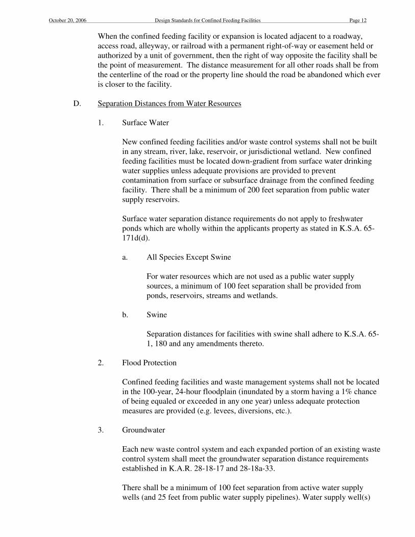
When the confined feeding facility or expansion is located adjacent to a roadway,
access road, alleyway, or railroad with a permanent right-of-way or easement held or
authorized by a unit of government, then the right of way opposite the facility shall be
the point of measurement. The distance measurement for all other roads shall be from
the centerline of the road or the property line should the road be abandoned which ever
is closer to the facility.
D. Separation Distances from Water Resources
1. Surface Water
New confined feeding facilities and/or waste control systems shall not be built
in any stream, river, lake, reservoir, or jurisdictional wetland. New confined
feeding facilities must be located down-gradient from surface water drinking
water supplies unless adequate provisions are provided to prevent
contamination from surface or subsurface drainage from the confined feeding
facility. There shall be a minimum of 200 feet separation from public water
supply reservoirs.
Surface water separation distance requirements do not apply to freshwater
ponds which are wholly within the applicants property as stated in K.S.A. 65-
171d(d).
a. All Species Except Swine
For water resources which are not used as a public water supply
sources, a minimum of 100 feet separation shall be provided from
ponds, reservoirs, streams and wetlands.
b. Swine
Separation distances for facilities with swine shall adhere to K.S.A. 65-
1, 180 and any amendments thereto.
2. Flood Protection
Confined feeding facilities and waste management systems shall not be located
in the 100-year, 24-hour floodplain (inundated by a storm having a 1% chance
of being equaled or exceeded in any one year) unless adequate protection
measures are provided (e.g. levees, diversions, etc.).
3. Groundwater
Each new waste control system and each expanded portion of an existing waste
control system shall meet the groundwater separation distance requirements
established in K.A.R. 28-18-17 and 28-18a-33.
There shall be a minimum of 100 feet separation from active water supply
wells (and 25 feet from public water supply pipelines). Water supply well(s)

October 20, 2006 Design Standards for Confined Feeding Facilities Page 13
located less than 100 feet from a confined feeding facility may be exempted if
used only for livestock water supply and if protected from surface water
contamination.
Monitoring wells if required, shall be installed per K.A.R. 28-30-1 et seq.,
using a licensed water well contractor.
E. Geologic Investigation
When necessary, the Department may require a site investigation, such as when the
confined feeding facility is to be located in a sensitive groundwater area, or the depth
to groundwater or the composition of the soil at the location is unknown, or similar
situation. Site investigations for earthen retention structures will consist of borings or
equivalent excavations to a depth of at least 10 feet below the lowest elevation of a
waste storage structure, or where impenetrable bedrock is encountered, whichever is
less. For swine facilities with more than 3,724 animal units, borings or equivalent
excavations to a depth of at least 25 feet below the lowest elevation of a waste storage
structure is recommended.
At least two borings or equivalent excavations shall be performed for each three (3)
acres occupied by a waste storage structure; a minimum of two borings are required
regardless of size. The area occupied by the structure is the surface area measured at
the top elevation.
The minimum requirements for geologic site investigations are:
1. Logging all borings or investigations using the Unified Soil Classification
System.
2. Recording the ground surface elevation and location of each boring. Elevation
may be based upon project datum (bench mark).
3. Measuring and recording static groundwater levels after the levels have
stabilized. (In the event that no water is readily evident, the boring or
excavation shall be left open a minimum of 24 hours, or more as required by
the Department. The required time frame will depend upon the soil profile, and
soil survey or lithology and shall be selected in order to adequately determine
the presence or lack of groundwater. The less permeable the soils, the greater
the time requirement. If no water is observed after the required time period, a
determination of Ano groundwater@ shall be entered. Groundwater wells in the
vicinity may be accepted by the Department as proof of local groundwater
levels on a case-by-case basis.)
4. Filling of all investigation borings or excavations in accordance with K.A.R.
28-30-1 et seq.
5. A brief summary indicating the likely impacts the observed geologic conditions
will have on the performance of the waste storage structure.
October 20, 2006 Design Standards for Confined Feeding Facilities Page 14
IV. Minimum Design of Wastewater Control Structures
A. General
The design storm for a facility is based upon the size of the facility and if applicable
the federal effluent limitation guideline for the type of livestock at the confined feeding
facility. All facilities with a federal animal unit capacity of less than 1,000 shall use a
25-year, 24-hour storm for the basis of design. All facilities required to have an
NPDES permit shall use the criteria specified in 40 CFR 412.
Collection and storage systems shall be designed to contain and/or convey: (1) surface
drainage from open lots, (2) manure and wastewater from confinement areas, and/or
(3) other flows such as dry weather wastewater accumulations. The channels, ditches,
berms, culverts, pipelines, dikes, terraces, pits, tanks, ponds, lagoons, and other
devices used to contain and/or convey runoff and/or pollutants have site specific
conditions. Drains and pipes are to be designed to facilitate cleanout, convey daily and
maximum flows, and minimize solids deposition.
Unpolluted extraneous drainage from areas adjacent to the confined feeding facility
may be diverted away from the confined feeding facility. If extraneous drainage is not
diverted away, the collection and storage system(s) must be sized to include these
flows.
B. Open Channel Structures
All channels, ditches, berms, dikes, terraces, and diversions shall be designed to collect,
and convey the peak discharge from the design storm event plus the sediment yield and the
maximum daily process wastes without overtopping or failure.
Velocities should be non-erosive (generally less than 2.5 feet per second for extraneous
runoff and 1.5 feet per second for polluted runoff) with the structure providing 0.5 foot of
freeboard. Earthen side slopes shall be 3 horizontal to 1 vertical (3:1) or flatter.
C. Closed Conduits
Culverts, pipes, and covered channels used to transfer runoff, sediment, and/or process
wastes shall be sized to handle the design storm event without causing infringement on the
freeboard of other structures in the system. Conduits shall be a minimum of 6 inches in
diameter and have a minimum slope of 0.5%. Drain pipes for water tank overflows can be
of a less diameter, but must be sized to handle the design flow. Cleanouts should be
located at least every 300 feet and at changes in direction and/or grade.
Conduit slopes should not exceed 10%. Designs should consider measures which will
prevent plugging of the inlet and which allow cleanout of the pipe or conduit (i.e. removal
of sediment and waste accumulations).

October 20, 2006 Design Standards for Confined Feeding Facilities Page 15
D. Basins and Structures
1. Sedimentation Structures
a. General
The purpose of sedimentation structures is to reduce solids/sludge
accumulations in storage structures and facilitate the routine removal of
solids/sludge. These standards address two of the most common types of
sediment basins, those for removing solids from feedlot runoff (runoff
sediment basins) and those for removing solids from process wastes (process
waste sediment basins) such as milking centers. All earthen structures shall
have side slopes of 3 horizontal to 1 vertical (3:1) or flatter. Sedimentation
basins shall have at least one-half (0.5) foot of freeboard at the design
condition.
b. Runoff Sediment Basins
Runoff sediment basins shall have capacities to detain the design storm
rainfall and runoff in addition to sediment for the design detention period for
the design storm, with 0.5 foot of freeboard. The minimum detention period
for the structure should be 4 hours. Flood routing procedures should be used
to determine the required discharge based upon the detention storage
provided. Discharges may be controlled by weirs, orifices, or other devices.
Runoff sediment basins should be dewatered as quickly as possible, within a
maximum of 10 days after a storm event. The volume allocated to sediment
storage shall be the expected annual sediment yield as a minimum. If the
sediment basin is not designed to completely dewater, then the basin must
have a liner designed in accordance with Retention Structure liner
requirements.
c. Process Waste Sediment Basins
Process waste sediment basins should have consideration given to drying of
the waste to allow for removal. Each process waste sediment basin should
be sized with a minimum capacity of thirty days of process waste flows.
Process waste sediment basins shall be lined in the same manner and to the
same criteria as retention structures. Consideration should be given to
sediment removal equipment and practices to minimize damage to the liner.
2. Retention Structures
Individual or combinations of retention structures must provide the total
required storage volumes as outlined in Aa. Hydraulic Volume Calculations@
and if necessary Ab. Biological Volume Calculations@, which follow.
a. Hydraulic Volume Calculations
i. Sediment Accumulation

October 20, 2006 Design Standards for Confined Feeding Facilities Page 16
All retention structures serving open lots shall provide for at
least the volume of sediment generated in a 10-year period. As
an alternative to site-specific information, if a sediment basin
precedes the retention structure, the sediment load may be
calculated at 0.5 acre-inch per acre of lot area drained. If there
is no sediment basin, a minimum of 1.5 acre-inch per acre of lot
drained may be used.
ii. Process Waste (Dry Weather Flows)Volume
All retention structures receiving dry weather process wastes
(for example overflow waterer discharges, milking parlor
discharges, free stall alley flushes silo liquors, and swine
building flushes) shall provide for the volume (including
bedding, litter, etc.) equal to or greater than the amount of dry
weather process waste delivered in a minimum period of 120
days.
The solids volume amount may be reduced up to 20% if the
retention structure is preceded by a sedimentation structure or
solids separator. In the case of recycle systems, net volumes
may be considered.
iii. Net Inflow (Rainfall/Runoff/Evaporation) Volume
Designers of retention structures should give consideration to
providing for an additional volume of the December 1 through
March 31 of the sum of the volumes produced from:
$ Runoff generated from precipitation on any contributing
drainage area,
$ The precipitation on the structure,
$ The evaporation loss on the structure.
For estimating the volume due to precipitation, the area at the
top of the structure shall be used. For estimating evaporation
loss, the December 1 operating level may be used. The
evaporation loss should be calculated using evaporation rates no
greater than 70% of the lake evaporation for the county where
the facility is located. Lake evaporation values may be obtained
through the County Natural Resources Conservation Service
Field Office.
A water budget may be used to determine the net inflow
volume. At no point in the water budget, shall the sum of the
net inflow and process waste volumes be less than zero.
October 20, 2006 Design Standards for Confined Feeding Facilities Page 17
iv. Storm Water Volume
All retention structures shall provide for a volume which will
contain the design storm runoff from any contributing drainage
area (including extraneous areas) plus the design storm rainfall
on the structure.
v. Freeboard
All newly proposed earthen retention structures shall have a
minimum of 2 feet of freeboard. All retention structures of non-
earthen material, such as concrete or fiberglass, shall provide 0.5
foot of freeboard. Wastewater should not be allowed to
encroach upon the freeboard level.
b. Biological Volume Calculations
Some confined feeding facilities generate waste which contains
negligible amounts of dilution water from runoff induced rainfall,
washdown or flushing, etc. These are primarily facilities with
confinement buildings such as swine facilities (with pull-plug systems
and/or recycling of wastewater), and dairies without overland flow
contributions. Retention structures for these facilities should contain a
minimum biological activity volume in order to operate properly.
Facilities which dry scrape waste accumulations and/or those with fresh
water flush gutters usually will not need a minimum biological volume.
A minimum biological volume should be considered in retention
structures at all facilities with 1,000 or more animal units which 1) have
swine in confinement buildings, 2) accept dairy parlor wastes, or 3) are
required by the Department to provide a minimum biological volume.
The biological volume calculation shall be made in addition to the
previously stated hydraulic volume calculations. Retention structures
shall be sized to always maintain the biological volume while reserving
space for any required hydraulic volume(s).
Retention structures shall have a supplemental water source to maintain
an adequate volume and to dilute waste inflows. The supplemental
water source may be either a surface or groundwater supply and should
be capable of delivering sufficient water to maintain the minimum
biological activity volume considering peak evaporation. Plans shall
include an operational section which identifies supplemental water
sources, requirements, and discusses the methods to be employed to
initially establish and maintain the minimum water level, and the
system for waste utilization.
Single stage retention structures and primary cells in two stage designs
for these types of facilities shall be designed for a daily loading rate not
to exceed the pounds of volatile solids (V.S.)/1000 ft.3 of retention

October 20, 2006 Design Standards for Confined Feeding Facilities Page 18
structure volume listed in the following table shown for each county in
Kansas. The values shown were obtained from Figure 10-22 Anaerobic
Lagoon Loading rates by the United States Department of Agriculture,
Natural Resources Conservation Service, revised June 1995, Part 651,
Agricultural Waste Management Field Handbook.
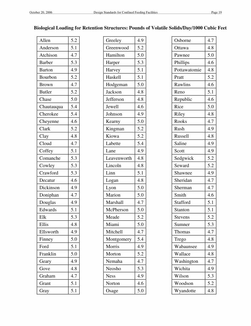
October 20, 2006 Design Standards for Confined Feeding Facilities Page 19
Biological Loading for Retention Structures: Pounds of Volatile Solids/Day/1000 Cubic Feet
Allen
5.2
Greeley
4.9
Osborne
4.7
Anderson
5.1
Greenwood
5.2
Ottawa
4.8
Atchison
4.7
Hamilton
5.0
Pawnee
5.0
Barber
5.3
Harper
5.3
Phillips
4.6
Barton
4.9
Harvey
5.1
Pottawatomie
4.8
Bourbon
5.2
Haskell
5.1
Pratt
5.2
Brown
4.7
Hodgeman
5.0
Rawlins
4.6
Butler
5.2
Jackson
4.8
Reno
5.1
Chase
5.0
Jefferson
4.8
Republic
4.6
Chautauqua
5.4
Jewell
4.6
Rice
5.0
Cherokee
5.4
Johnson
4.9
Riley
4.8
Cheyenne
4.6
Kearny
5.0
Rooks
4.7
Clark
5.2
Kingman
5.2
Rush
4.9
Clay
4.8
Kiowa
5.2
Russell
4.8
Cloud
4.7
Labette
5.4
Saline
4.9
Coffey
5.1
Lane
4.9
Scott
4.9
Comanche
5.3
Leavenworth
4.8
Sedgwick
5.2
Cowley
5.3
Lincoln
4.8
Seward
5.2
Crawford
5.3
Linn
5.1
Shawnee
4.9
Decatur
4.6
Logan
4.8
Sheridan
4.7
Dickinson
4.9
Lyon
5.0
Sherman
4.7
Doniphan
4.7
Marion
5.0
Smith
4.6
Douglas
4.9
Marshall
4.7
Stafford
5.1
Edwards
5.1
McPherson
5.0
Stanton
5.1
Elk
5.3
Meade
5.2
Stevens
5.2
Ellis
4.8
Miami
5.0
Sumner
5.3
Ellsworth
4.9
Mitchell
4.7
Thomas
4.7
Finney
5.0
Montgomery
5.4
Trego
4.8
Ford
5.1
Morris
4.9
Wabaunsee
4.9
Franklin
5.0
Morton
5.2
Wallace
4.8
Geary
4.9
Nemaha
4.7
Washington
4.7
Gove
4.8
Neosho
5.3
Wichita
4.9
Graham
4.7
Ness
4.9
Wilson
5.3
Grant
5.1
Norton
4.6
Woodson
5.2
Gray
5.1
Osage
5.0
Wyandotte
4.8

October 20, 2006 Design Standards for Confined Feeding Facilities Page 20
3. Design Criteria for Earthen Structures
a. Liners
Liners shall extend over the bottom and side slopes of the interior of the
structure to an elevation at least 1 foot above the freeboard level. Liners
shall have a finished or compacted final thickness of at least 1 foot.
Where consolidated material such as a rock layer is encountered, the
liner shall have a final thickness of at least 2 feet. Any areas
overexcavated to remove undesirable material such as rock, must be
backfilled with compacted material.
i. In-Situ Soil Liners
In-situ soil liners may be acceptable for sites where no
groundwater, bedrock or other consolidated material is
encountered within the required geologic site
investigation. Where this is the case, soils found during
the site investigation must be classified as CH, MH, or
CL according to the Unified Soil Classification System
in order to be used as in-situ soil liners.
ii. Constructed Soil Liners
Constructed soil liners are those which do not conform
to the criteria for in-situ soil liners.
During the geologic investigation, soil samples shall be
collected, logged and prepared for testing. The samples
must be representative of the foundation and perimeter
material encountered and any materials which may be
used for soil liners.
The soil samples shall be subjected to accepted
laboratory tests to determine the materials and
construction techniques required to provide adequate
permeability. These tests may include, but may not be
limited to, moisture-density tests to determine moisture
and compaction requirements, soil amendment tests
including those to determine the amount of bentonite,
chemical dispersants or other materials needed to
provide acceptable permeability.
A design must then be developed and documented which
determines the amount and type of amendment materials
required, if any, the construction techniques required and
the projected permeability.
October 20, 2006 Design Standards for Confined Feeding Facilities Page 21
Post-construction permeability tests must be completed
and the results submitted to the Department for review.
iii. Synthetic Liners
Synthetic liners shall be installed when the required
permeability cannot be achieved and/or when required
by the Department. They shall be installed in addition to
a compacted soil liner. Synthetic liners shall have a
minimum thickness of 40 mils, and a permeability of
1/64 inch per day or less. They shall be designed and
installed in conformance with the manufacturers
specifications.
b. Embankment Foundation and Fill
Embankment berms shall have a minimum top width of ten (10) feet
and shall be constructed of compacted soils essentially void of rock,
gravel, sand, organic material, or other porous media. All vegetation
shall be removed from the foundation and fill areas prior to the
placement of earth fill.
c. Emergency Spillways
Retention structures which have an embankment height of 25 feet or
more, or which impound 50 acre-feet (2,178,000 ft 3) or more and have
a height of 6 feet or more shall have emergency spillways. The height
shall be determined by measuring from the lowest elevation of the
outside limit of the dam to the top of the dam. Emergency spillways
shall be designed in conformance to the Kansas Department of
Agriculture, Division of Water Resources requirements.
The crest of each emergency spillway shall be a minimum of one foot
above the level associated with the total required design volume.
d. Inlets
All inlets shall be designed to provide erosion protection of
impoundment embankments. Splash pads, riprap, or other devices shall
be provided as needed.
e. Depths
The maximum design depth of newly proposed waste storage structures,
not including freeboard, is 20 feet.
October 20, 2006 Design Standards for Confined Feeding Facilities Page 22
For single cells and primary cells in multiple-cell systems which must
contain a minimum biological volume, the minimum depth shall be 8
feet. They shall be maintained with at least a minimum water depth of
5 feet. Secondary cells shall be a minimum of 6 feet deep.
A staff gauge or level measurement device shall be installed in each
retention structure (lagoons, ponds, etc.). The device shall be:
$ constructed of durable material
$ marked in 1-foot (vertical) increments
$ marked with zero to coincide with the lowest point of the top of
the structure berm
4. Non-earthen Structures
The allowance for sediment accumulation may be reduced to the bottom 6
inches of the water-tight structure so long as agitation and pumping equipment
is capable of draining the structure.
a. Concrete Tanks
All concrete manure tanks shall be constructed with reinforced concrete
in a water tight manner. Side walls shall be a minimum of 6 inches
thick and tank bottoms a minimum of six (6) inches thick. Professional
design assistance is required in the design of these watertight structures.
b. Metal, Fiberglass, and Other Storage Vessels
Several manufacturers provide prefabricated storage structures
consisting of stave concrete silos, epoxy lined metal tanks, etc. These
storage structures shall be of water tight construction and of quality
design. These and other designs will be individually evaluated.
5. Solid Waste Storage Structures
a. General
Solid waste storage structures receive scraped or mechanically
deposited manure, bedding, litter, etc., for temporary storage before
land application, before use in composting facilities, or before final use.
b. Design Criteria
These structure(s) shall be sized to store the expected accumulation of
manure, bedding, litter, etc., and the volume of direct precipitation from
the design storm plus a 0.5-foot reserve.
October 20, 2006 Design Standards for Confined Feeding Facilities Page 23
The combined volumes of solid waste storage structures, other
associated storage structures and temporary storage and/or stacking
areas must have the capacity to contain the 120 day solid waste
accumulation volume.
Any contaminated leachate and/or runoff from solid waste storage
structures must be controlled. If necessary, control structures shall be
built to detain runoff.
6. Hoop Structures
Hoop or Deep-bedded structures are partially or totally enclosed units for
housing livestock. The units utilize absorbent material (hay, stover, fodder, or
straw) spread throughout the floor of the unit. The deep layer of absorbent
material soaks up the liquid portion of the manure and dries the semi-solid
portion of the manure so the animal excrement can be managed in dry or solid
form.
a. Hoop structures shall have a finished grade of 0.5% slope or less.
Extraneous drainage shall be diverted away from the structure. Site
grading shall be such that roof and other runoff is directed away from
the structure.
b. Hoop structures must meet the same vertical separation distance to
groundwater as feedlots. Structures located in a sensitive groundwater
area where groundwater is within 25 feet of the lowest elevation of the
structure shall have a compacted soil liner. The compacted soil liner
shall be a minimum of 12 inches thick and shall have a hydraulic
conductivity no greater than 10-7
cm/sec or utilize other materials or
methods which provide the same level of protection to the groundwater.
c. Hoop structures shall be capable of providing a minimum of 120 days
of solids storage. Solid waste stockpiles shall be temporary, not to
exceed six (6) months. Stockpiles shall be located such that runoff from
the stockpiles does not enter or collect adjacent to the structure.
7. Other Structures Not Typically Used in Kansas
From time to time, situations arise which may call for innovative use of
methods or structures not covered in these standards such as aerobic lagoons,
mechanically aerated lagoons or digesters (methane gas production systems),
etc. These will be considered on a case-by case basis. Complete design
documentation showing technical references shall accompany the plans and
shall describe how the proposed method will provide a level of protection
consistent with the intent of these standards and applicable federal and state
laws and regulations.
October 20, 2006 Design Standards for Confined Feeding Facilities Page 24
E. Grass Filter Systems
The purpose of grass filter systems is to protect and improve water quality by
removing significant amounts of pollutants generated by confined feeding facilities.
These systems use the processes of deposition, infiltration, absorption, volatilization,
vegetative consumption and decomposition.
Grass filter systems are not suitable for most confined feeding facilities. Suitability
generally depends upon the facility=s size, setting and process waste characteristics.
Grass filter systems are generally limited to facilities with less than 300 animal units.
Grass filter systems proposed for facilities with 300 or more animal units will be
considered on a case-by-case basis.
Grass filter systems usually consist of at least three components: sediment basin, flow
distribution devices and grass filter area. The grass filter is an area of perennial grass
used to reduce sediment, organic waste, nutrients and other pollutants from stormwater
runoff from confined feeding facilities. The design of each grass filter system should
be based upon the most current Kansas NRCS practice standard for Wastewater
Treatment Strip (Practice Code 635). The performance objectives of each component
are:
1. Sediment Basin
a. Have the capacity to store the average annual sediment yield from the
lot.
b. Detain lot runoff to induce the settling or deposition of solids and
nutrients.
c. Provide controlled outflow to the grass filter area.
d. Detain the design storm event without overtopping or having an
uncontrolled discharge.
e. Facilitate maintenance, especially sediment removal.
2. Flow Distribution System
a. Uniformly distribute sediment basin discharge onto the grass filter area.
b. Provide the inflow, velocity and flow depth to the grass filter area
required to meet hydraulic performance criteria.
3. Grass Filter Area
a. Infiltrate the sediment basin discharge resulting from a 2-year, 24-hour
storm event and the direct rainfall on the filter area. The soil in the

October 20, 2006 Design Standards for Confined Feeding Facilities Page 25
filter area shall be a minimum of 2 feet deep. The available water
capacity of the soil shall be assumed to be 50% before the storm occurs.
b. Control the sediment basin discharge resulting from a 25-year, 24-hour
rainfall event such that: all flow is controlled within the filter area, flow
depth does not exceed 6 inches, average velocity does not exceed 1.5
ft./sec., and contact time (i.e. travel time) through the filter area is at
least one hour.
c. Ensure uniform sheet flow by utilizing methods such as dividing the
filter into borders having a maximum width of 50 feet.
d. Distribute and apply nutrients at agronomic rates.
F. Livestock Truck/Trailer Washes
1. General
The design of each Livestock Truck/Trailer Wash (LTTW) should be based
upon site-specific information whenever possible rather than the general
criteria provided below. These criteria are intended for use in the design of
truck washes used for the washing of trucks and trailers used for livestock
transportation only. Any other type of truck/trailer wash or a combined
washing facility serving livestock truck/trailers and other types of truck/trailers
or vehicles are required to meet other requirements not addressed by these
standards.
Usually, a LTTW producing livestock related waste should consist of the
following components: washwater collection area, solid separation and/or
storage (sediment basin, mud trap, etc), wastewater storage, and waste
utilization.
2. Design Criteria
a. Settling basin shall be sized for at least 30 minutes retention time.
b. Settling basin shall allow for 10 ft3 per truck washed for solid storage
with no less than one month cleanout interval.
c. If any on-site solids storage is provided it must be sized to hold 120
days of solids. Any runoff from the solids storage site must be directed
to the wastewater storage structure.
d. Minimum wastewater storage shall be designed as provided in other
sections of these Design Standards. If actual quantities or book values
are not available, a minimum storage volume of 270 ft3 of wastewater
per truck shall be provided.

October 20, 2006 Design Standards for Confined Feeding Facilities Page 26
e. Land application area may be estimated using 0.008 acre for each truck
washed annually for liquids disposal area and 0.027 acre for each truck
washed annually for solid disposal area.
G. Public Livestock Markets
From a hydraulic or drainage standpoint, waste systems for public livestock markets
shall adhere to the design requirements for confined feeding facilities contained herein.
For nutrient utilization, however, the design shall be based on the expected average
annual number and type of animals to be sold by the market. Nutrient loads shall be
determined for each animal type represented, taking into account the average number
of days and/or hours the animal would be present at the facility. The various waste
loads shall then be aggregated. Book values may be used in determining the waste
loading.
Nutrient loadings for existing public livestock markets shall be computed utilizing the
average annual number and type of animals sold by the market during the past five
calendar years, taking into account the average number of days and/or hours the
animals are present at the facility.
H. Composting Operations
Any contaminated leachate and/or runoff must be controlled. If necessary, structures
shall be built to control the runoff. The facility=s “Kansas Water Pollution Control
Permit For Agricultural and Related Wastes@ will include retention structures within
the facility=s drainage control area, including any receiving runoff from composting.
The proper operation of composting operations and any control structures outside the
facility=s drainage control area shall be subject to the Department=s Bureau of Waste
Management regulations, permitting, inspection and oversight (See K.A.R. 28-19-25c
and 25d).
V. Construction
A. Required Construction Time Frames
1. Newly Proposed Construction
Construction initiation and completion of approved new facilities or
expansions of existing facilities shall adhere to the time frames in K.A.R. 28-
18-12 (e) and/or K.A.R. 28-18a-12 (e). Failure to initiate and complete the
approved construction in the appropriate time frame(s) shall void the
Department=s approval of the construction plans, specifications, and other
associated plans.
2. Voided Approval/Resubmitting Plans
In cases where the Department=s approval becomes void due to a construction
October 20, 2006 Design Standards for Confined Feeding Facilities Page 27
time frame failure, the permit or permit modification shall remain in effect for
the term of the permit. If the applicant desires to construct the proposed new
facility or expanded facility after the approval has become void, the previously
approved construction plans, specifications, and other associated plans may be
resubmitted for review and approval, but must include any modifications to
meet current requirements. The applicant shall not initiate construction or
expansion prior to the Department=s approval of the resubmitted plans.
B. Discoveries During Construction
If an active, abandoned, or plugged water, oil or gas well, pipeline or similar feature is
found to be in a location other than that shown on the approved plans, the Department
shall be notified within 48 hours of discovery. Construction activities relative to the
well, pipeline or feature in the vicinity shall immediately halt and shall not resume
until authorization is given.
If a discovery necessitates changes to the approved plan, proposed changes shall be
submitted for review and approval prior to implementation. Any approved
modifications shall be incorporated into the permit upon renewal.
Archaeological discoveries such as human remains shall be dealt with according to
K.S.A. 75-2741 through 2754.
C. Soil Liners
Care should be taken not to allow soil liners to dry out during and after construction.
Cracked soil liners must be repaired prior to permeability testing or acceptance by the
Department.
D. Post-Construction Permeability Tests
1. General
Construction observation and testing is required for each waste control
structure required to be watertight or to control seepage to established
requirements. Unless specific test methods are required by regulation or
statute, any of the following methods may be utilized:
a. Individual sample methods such as the core sample method
b. Whole lagoon or whole pond method
c. Construction oversight method
d. Other methods approved by the Department
For individual sample methods, one sample site per acre occupied by the waste

October 20, 2006 Design Standards for Confined Feeding Facilities Page 28
control structure shall be selected for testing. The area occupied by the
structure is the surface area measured at the top of berm elevation. Fractional
acres shall be rounded up to the next whole number. Retention structures shall
be treated separately from one another in the surface area calculations and the
testing. No less than one sample site per waste control structure shall be
selected for testing.
If the core sample method is used, samples must be analyzed by a laboratory
familiar with soil testing. Core samples shall be representative of the
constructed soil liner and shall not be mixed with one another. Samples shall
be complete unified soil masses and shall not be re-molded. The soil cores
shall be collected in accordance with ASTM D-1587 preserved in accordance
with ASTM D-4220 and tested in accordance with ASTM D-5084 methods.
Any holes resulting from core samples shall be filled with bentonite or other
approved material(s).
Materials and equipment to be used in field or site tests shall be subject to
approval by the Department prior to testing. The Department shall be notified
at least 48 hours in advance of a field test and given an opportunity to view and
record the test procedures and readings or the test results will not be accepted.
The whole pond seepage test as described in ASAE Paper Number 034130 is
suitable for testing impermeable synthetic membrane liners or soil liners.
If the construction oversight method is used, a geologic survey must be
completed with the pre-construction soil samples tested and a liner design
developed as herein described. The construction shall be observed to ensure
correct construction methods are being used, and proper compaction is being
achieved. After construction, consideration should be given to construction
quality assurance testing such as core sample or whole pond test methods when
the construction oversight method is used.
Permeability test results shall be submitted to the Department within thirty (30)
days of test completion. Tests results must be approved by the Department
prior to populating the facility. Should any structure not meet the permeability
requirements, additional sealing will be required.
If a synthetic liner is to be installed, permeability tests shall be completed,
submitted and approved prior to the placement of the synthetic liner.
The permittee may also propose and use any other methods approved by the
Department.
2. Compaction Testing
Compaction testing may be done utilizing nuclear gage moisture density
determination or other methods approved by the Department. Nuclear density

October 20, 2006 Design Standards for Confined Feeding Facilities Page 29
testing may only be done on horizontal surfaces as indicated in ASTM D-2922.
Pre-construction laboratory test results showing the corresponding density and
moisture parameters shall be submitted to the Department with the permit
application. A minimum of one site for every 10,000 square feet of the area
occupied by the structure shall be tested. The waste retention structures shall
be treated separately from one another in the surface area calculations and the
testing.
E. Synthetic Liners
The manufacturer specifications including installation and testing protocols shall be
provided to the Department with the permit application. Prior to commencing
operations at the site, a certification that the liner was installed consistent with the
manufacturers= specifications shall be provided to the Department by a professional
engineer licensed to practice in Kansas or an approved consultant.
F. Completion Certification
Following the completion of construction of a new or expanded portion of a confined
feeding facility with a waste control system, a completion certification, and when
requested, any supporting documentation shall be submitted to the Department. It
shall certify that the waste control system was constructed in accordance with the plans
and specifications approved by the Department. For facilities designed by an approved
consultant, the consultant shall sign and submit the certification. Where there is no
consultant, the applicant shall sign and submit the certification.
VI. Operation and Maintenance
A. Initiating Operations
The operation of a new confined feeding facility or expanded portion of an existing
facility or waste control system shall not be initiated until after issuance of the new or
modified permit.
B. Required Retention Structure Operating Levels
Most retention structures are required to have maximum and sometimes a minimum
operating level or range as stated in the facility=s permit. The level will be measured
from the lowest point on the top of the berm and/or referenced to the bottom of the
retention structure and will be stated in feet.
Usually, facilities with daily flows will have a required normal operating level and/or a
December 1st or winter operating level. Facilities without daily flows generally have
only a normal operating level. Facilities which must have a minimum biological
volume will have the minimum required biological volume level stated in their permit
in addition to other required levels.
October 20, 2006 Design Standards for Confined Feeding Facilities Page 30
When setting the required operating levels, the Department will include all facility
runoff including extraneous areas. Runoff curve number 90 will be used for all
unpaved lots, pens, feeding alleys, and roads. Runoff curve number 97 will be used for
roofs and all paved (concrete and asphalt) areas. All (100 percent) of the design storm
precipitation will be used on the retention structure area.
In order to facilitate control of the retention structure operating level(s), a staff gauge
or level measurement device shall be maintained in working order, in each retention
structure.
C. Solids Handling
1. Sedimentation Basins and Retention Structures
Sedimentation basins shall be cleaned annually or more frequently as needed to
ensure proper operation of the retention structures. Retention structures shall
be cleaned of solids accumulation whenever the accumulation infringes on the
required storage depth.
2. Open Lots
Open lots and facilities such as hoop structures which accumulate solid wastes
should be scraped or cleared of manure, bedding, etc., after each cycle. Manure
accumulations should be minimized during summer months or dry periods to
minimize off site deposition of dust and manure. Solid wastes may be
temporarily stockpiled not to exceed six (6) months. Stockpiles shall be
located such that runoff is controlled.
D. Waterers
When setting permit requirements, unless it is otherwise stated in the plans submitted,
the Department will assume that Acontinuous flow@ waterers will overflow only during
periods of potentially freezing weather. Malfunctioning waterers shall be repaired in a
timely manner such that excess flows do not impact the waste control system.
Waterers in hoop structures shall be located such that excess flow does not enter into
the pen area.
E. Erosion and Liner Protection
Perennial grass should be established on the side slopes above wastewater levels,
berms, and back slopes of all newly constructed or expanded earthen structures. Short-
rooted grass such as Bermuda, Fescue, Brome, Timothy, and native grasses are
suitable. Trees and/or other deep rooted vegetation must not be allowed to grow
within 100 feet of the outside toe of newly constructed or expanded earthen structures.
Fencing or other means shall be utilized to prevent animals from accessing or
disturbing earthen liners.
October 20, 2006 Design Standards for Confined Feeding Facilities Page 31
Earthen liners shall not be allowed to dry out thus risking the integrity of the seal. Any
mechanical or structural damage to the liner shall be reported to the Department within
two workdays of identification and shall be repaired in a time frame approved by the
Department.
Any erosion damage shall be repaired on all waste control structures in a timely
manner. All repairs shall conform to the approved plans and specifications.
VII. Waste Utilization
A. Land Application
Waste may be applied to agricultural land by any method that will result in uniform
application of the material and not exceed agronomic rates. Liquid wastes shall be
applied at agronomic rates and at rates less than or equal to the soil intake rates.
Wastes shall not be applied:
1. To areas within 100 feet of any down-gradient surface water, open tile line
intake structure, sinkhole, agricultural wellhead, or other conduit to surface
waters. The required distance may be reduced to 35 feet if a permanently
vegetated buffer is established where applications of manure, litter, or process
wastewater are prohibited.
2. As a liquid, when soil is frozen, snow-covered, saturated, or during a
precipitation event, unless approved in advance by the Department. (Solid
wastes may be applied to frozen ground if measures are taken to ensure that the
wastes will be retained at the application site).
3. To areas subject to active erosion, especially gully erosion.
4. At rates which allow the wastes to leave the land application site or property.
B. Application Equipment
The waste application equipment shall be sufficient to operate and manage the waste
control system as designed. Systems storing and handling liquid wastes shall maintain
application equipment capable of applying the ten (10) day wastewater accumulation
volume and the design storm (25-year, 24-hour) volume, in ten twelve-hour operating
days. For center-pivot sprinkler systems, 24-hour operating days may be considered
when determining the required minimum application rate.

October 20, 2006 Design Standards for Confined Feeding Facilities Page 32
Waste application equipment is to be owned, contracted, leased or under a use
agreement. Equipment obtained by lease or use agreement must be available for use
on-site within four working days.
C. Sampling
When directed by the Department, sampling and analysis of wastes and/or waste
application sites shall be conducted to confirm application of waste at agronomic rates.
D. Evaporative Utilization
Facilities which intend to utilize evaporation as a disposal method must develop a
water budget to determine the extent to which evaporation can control liquid wastes.
The design shall take into consideration sediment accumulation, process waste, net
inflow, storm water (from the design storm), freeboard and any required biological
volume. The area required for land application of liquid waste shall be based on
applying waste at agronomic rates. Application equipment capacity requirements will
be the same as for conventional land application systems. Salinity and water quality
testing shall be conducted on the wastewater in the storage structure as a condition of
permit renewal to determine the suitability of waste material for land application.
VIII. Variance Procedure
A. General
This section allows for innovative solutions to confined feeding facility waste control
systems. Situations may arise which, because of engineering considerations, industrial
practices, or new technology, may require variance from the criteria published in these
Design Standards. The Department of Health and Environment will consider requests
for variance from these Design Standards on a case-by-case basis. Such requests for
variance shall justify the need for a variance and show how the requested variance will
protect the surface and groundwater quality consistent with the intent of these Design
Standards.
B. Procedure
Requests for a variance shall be submitted in writing to the Department and will
address the following:
1. Purpose of the requested variance and why it should be considered/granted.
2. Section(s) of these Design Standards for which the variance is requested.

October 20, 2006 Design Standards for Confined Feeding Facilities Page 33
3. How the variance will be consistent with the intent of these Design Standards
and protect surface water and groundwater quality.
4. Any other information the Department may require to justify the request for
variance.
The Department will respond to a request for variance in writing and either deny,
grant, or conditionally approve the request.