Embed Size (px)
Citation preview
Design Submission Pack
For Independent Connection Providers
Electricity North West Ltd
29 September 2017
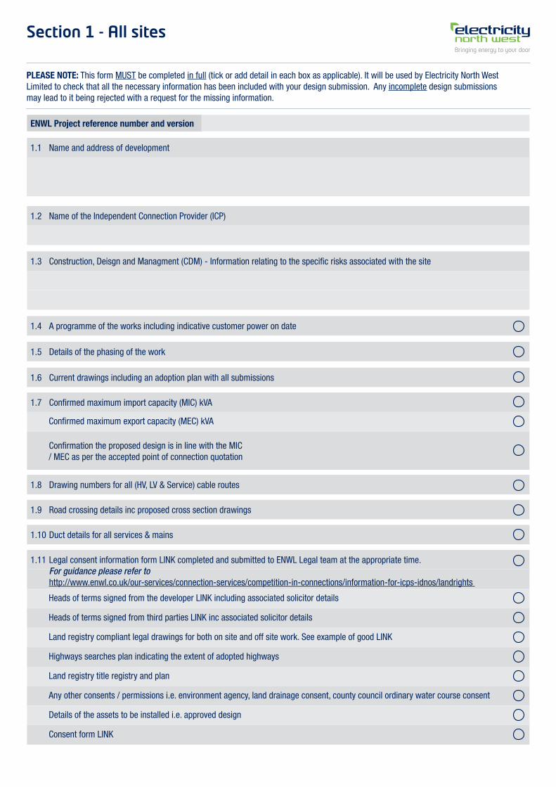
Section 1 - All sites
PLEASE NOTE: This form MUST be completed in full (tick or add detail in each box as applicable). It will be used by Electricity North West Limited to check that all the necessary information has been included with your design submission. Any incomplete design submissions may lead to it being rejected with a request for the missing information.
ENWL Project reference number and version
1.1 Name and address of development
1.2 Name of the Independent Connection Provider (ICP)
1.3 Construction, Deisgn and Managment (CDM) - Information relating to the specific risks associated with the site
1.4 A programme of the works including indicative customer power on date
1.8 Drawing numbers for all (HV, LV & Service) cable routes
1.9 Road crossing details inc proposed cross section drawings
1.10 Duct details for all services & mains
1.11 Legal consent information form LINK completed and submitted to ENWL Legal team at the appropriate time. For guidance please refer to http://www.enwl.co.uk/our-services/connection-services/competition-in-connections/information-for-icps-idnos/landrights
1.5 Details of the phasing of the work
1.6 Current drawings including an adoption plan with all submissions
1.7 Confirmed maximum import capacity (MIC) kVA
Confirmed maximum export capacity (MEC) kVA
Heads of terms signed from the developer LINK including associated solicitor details
Heads of terms signed from third parties LINK inc associated solicitor details
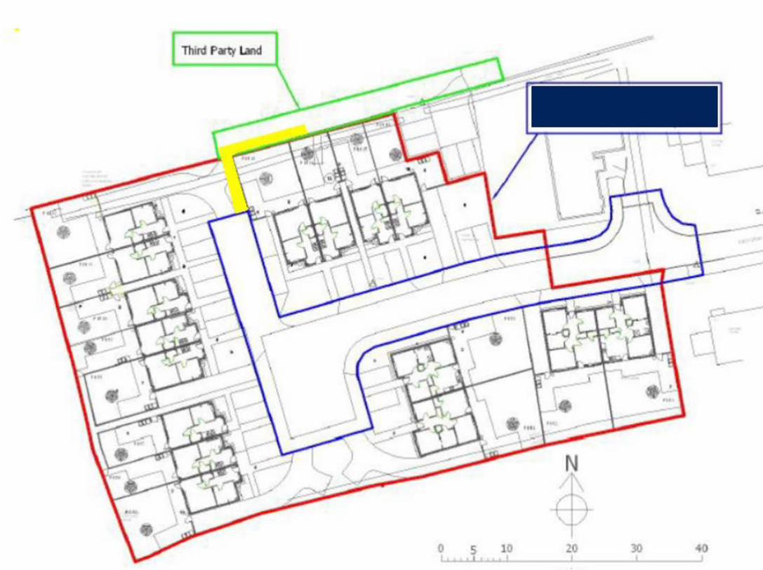
Land registry compliant legal drawings for both on site and off site work. See example of good LINK
Highways searches plan indicating the extent of adopted highways
Land registry title registry and plan
Any other consents / permissions i.e. environment agency, land drainage consent, county council ordinary water course consent
Details of the assets to be installed i.e. approved design
Consent form LINK
Confirmation the proposed design is in line with the MIC / MEC as per the accepted point of connection quotation
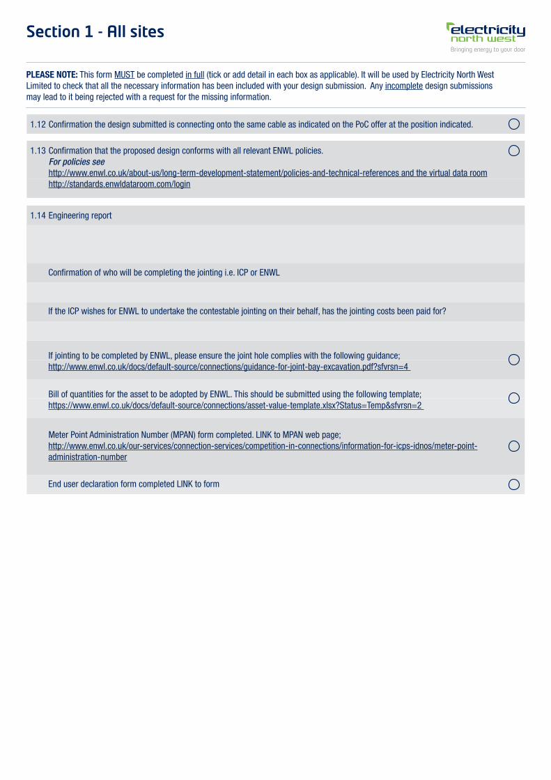
Section 1 - All sites
PLEASE NOTE: This form MUST be completed in full (tick or add detail in each box as applicable). It will be used by Electricity North West Limited to check that all the necessary information has been included with your design submission. Any incomplete design submissions may lead to it being rejected with a request for the missing information.
1.12 Confirmation the design submitted is connecting onto the same cable as indicated on the PoC offer at the position indicated.
1.13 Confirmation that the proposed design conforms with all relevant ENWL policies. For policies see http://www.enwl.co.uk/about-us/long-term-development-statement/policies-and-technical-references and the virtual data room http://standards.enwldataroom.com/login
1.14 Engineering report
Confirmation of who will be completing the jointing i.e. ICP or ENWL
End user declaration form completed LINK to form
If the ICP wishes for ENWL to undertake the contestable jointing on their behalf, has the jointing costs been paid for?
If jointing to be completed by ENWL, please ensure the joint hole complies with the following guidance; http://www.enwl.co.uk/docs/default-source/connections/guidance-for-joint-bay-excavation.pdf?sfvrsn=4
Meter Point Administration Number (MPAN) form completed. LINK to MPAN web page; http://www.enwl.co.uk/our-services/connection-services/competition-in-connections/information-for-icps-idnos/meter-point-administration-number
Bill of quantities for the asset to be adopted by ENWL. This should be submitted using the following template; https://www.enwl.co.uk/docs/default-source/connections/asset-value-template.xlsx?Status=Temp&sfvrsn=2
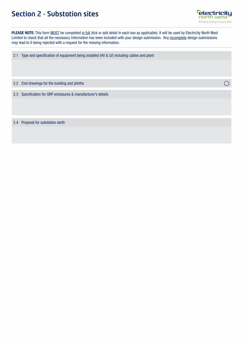
Section 2 - Substation sites
PLEASE NOTE: This form MUST be completed in full (tick or add detail in each box as applicable). It will be used by Electricity North West Limited to check that all the necessary information has been included with your design submission. Any incomplete design submissions may lead to it being rejected with a request for the missing information.
2.1 Type and specification of equipment being installed (HV & LV) including cables and plant
2.3 Specification for GRP enclosures & manufacturer’s details
2.4 Proposal for substation earth
2.2 Civil drawings for the building and plinths
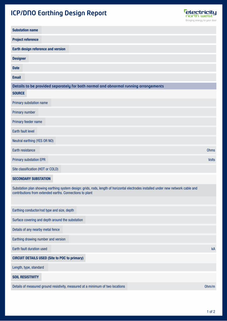
ICP/DNO Earthing Design Report
Substation name
SOURCE
SECONDARY SUBSTATION
CIRCUIT DETAILS USED (Site to POC to primary)
SOIL RESISTIVITY
Earth design reference and version
Date
Project reference
Designer
Primary substation name
Substation plan showing earthing system design: grids, rods, length of horizontal electrodes installed under new network cable and contributions from extended earths. Connections to plant
Primary number
Primary feeder name
Earth fault level
Neutral earthing (YES OR NO)
Earth resistance Ohms
Volts
kA
Ohm/m
1 of 2
Primary substation EPR
Site classification (HOT or COLD)
Earthing conductor/rod type and size, depth
Surface covering and depth around the substation
Details of any nearby metal fence
Earthing drawing number and version
Earth fault duration used
Length, type, standard
Details of measured ground resistivity, measured at a minimum of two locations
Details to be provided separately for both normal and abnormal running arrangements
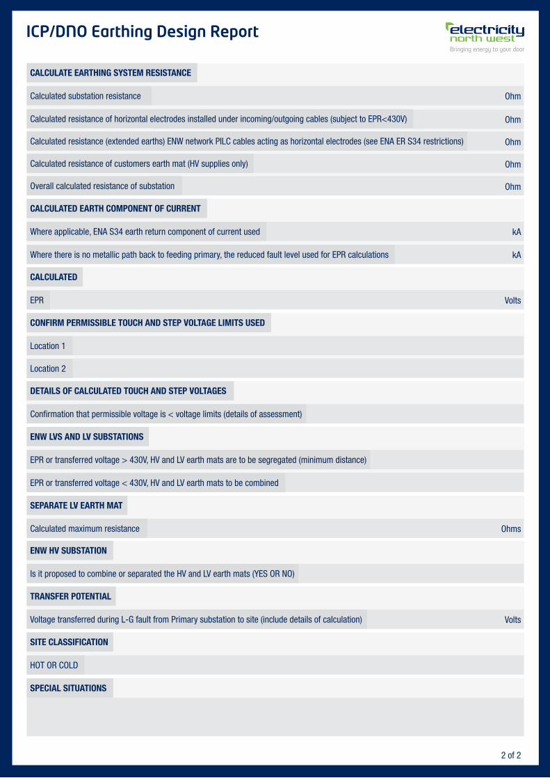
ICP/DNO Earthing Design Report
CALCULATE EARTHING SYSTEM RESISTANCE
CALCULATED EARTH COMPONENT OF CURRENT
CALCULATED
CONFIRM PERMISSIBLE TOUCH AND STEP VOLTAGE LIMITS USED
DETAILS OF CALCULATED TOUCH AND STEP VOLTAGES
ENW LVS AND LV SUBSTATIONS
SEPARATE LV EARTH MAT
ENW HV SUBSTATION
TRANSFER POTENTIAL
SITE CLASSIFICATION
SPECIAL SITUATIONS
Calculated substation resistance
Where applicable, ENA S34 earth return component of current used
EPR
Location 1
Confirmation that permissible voltage is < voltage limits (details of assessment)
EPR or transferred voltage > 430V, HV and LV earth mats are to be segregated (minimum distance)
Calculated maximum resistance
Is it proposed to combine or separated the HV and LV earth mats (YES OR NO)
Voltage transferred during L-G fault from Primary substation to site (include details of calculation)
HOT OR COLD
EPR or transferred voltage < 430V, HV and LV earth mats to be combined
Location 2
Where there is no metallic path back to feeding primary, the reduced fault level used for EPR calculations
Calculated resistance of horizontal electrodes installed under incoming/outgoing cables (subject to EPR<430V)
Calculated resistance (extended earths) ENW network PILC cables acting as horizontal electrodes (see ENA ER S34 restrictions)
Calculated resistance of customers earth mat (HV supplies only)
Overall calculated resistance of substation
Ohm
kA
Volts
Ohms
Volts
kA
Ohm
Ohm
Ohm
Ohm
2 of 2
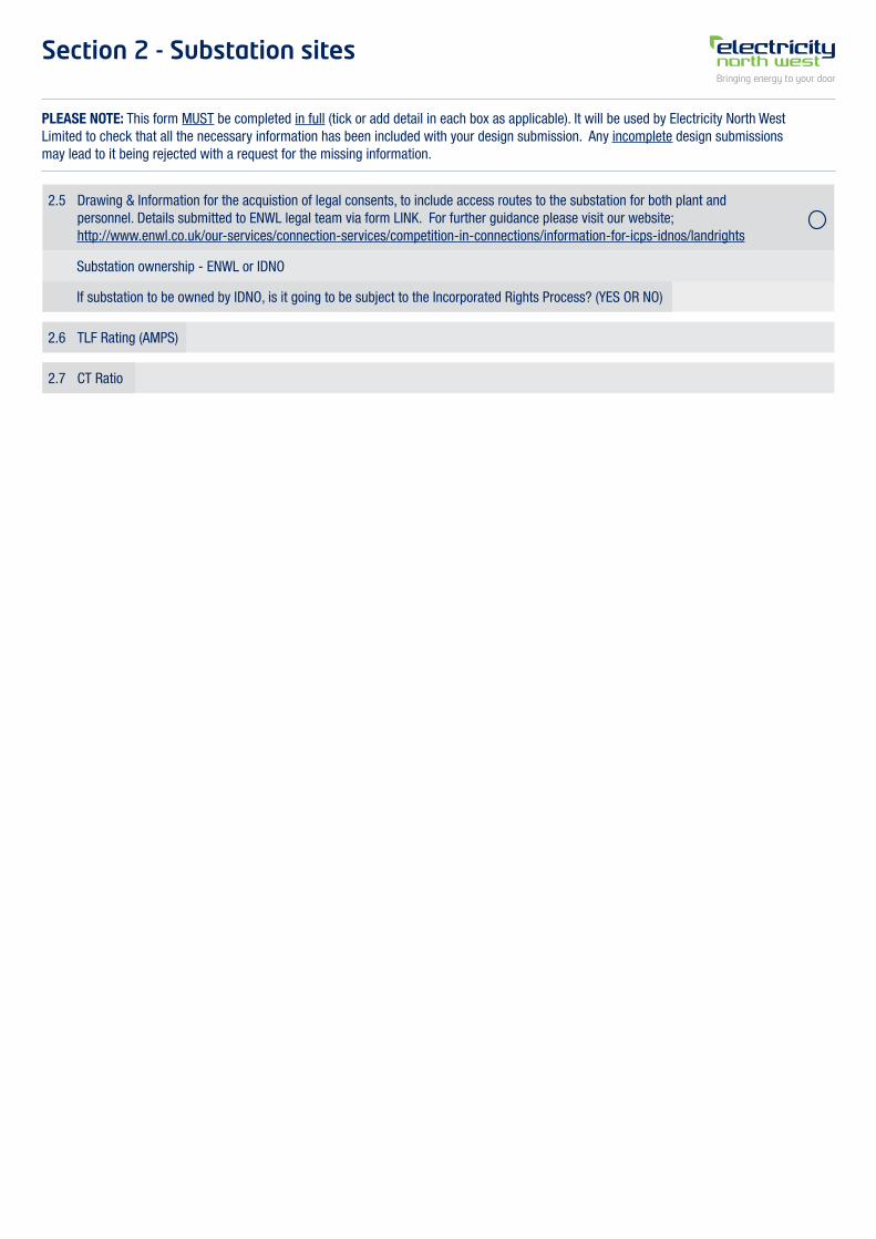
Section 2 - Substation sites
PLEASE NOTE: This form MUST be completed in full (tick or add detail in each box as applicable). It will be used by Electricity North West Limited to check that all the necessary information has been included with your design submission. Any incomplete design submissions may lead to it being rejected with a request for the missing information.
2.5 Drawing & Information for the acquistion of legal consents, to include access routes to the substation for both plant and personnel. Details submitted to ENWL legal team via form LINK. For further guidance please visit our website; http://www.enwl.co.uk/our-services/connection-services/competition-in-connections/information-for-icps-idnos/landrights
2.6 TLF Rating (AMPS)
2.7 CT Ratio
Substation ownership - ENWL or IDNO
If substation to be owned by IDNO, is it going to be subject to the Incorporated Rights Process? (YES OR NO)
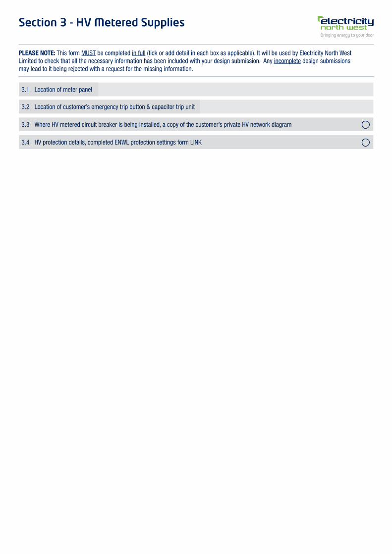
Section 3 - HV Metered Supplies
PLEASE NOTE: This form MUST be completed in full (tick or add detail in each box as applicable). It will be used by Electricity North West Limited to check that all the necessary information has been included with your design submission. Any incomplete design submissions may lead to it being rejected with a request for the missing information.
3.1 Location of meter panel
3.2 Location of customer’s emergency trip button & capacitor trip unit
3.3 Where HV metered circuit breaker is being installed, a copy of the customer’s private HV network diagram
3.4 HV protection details, completed ENWL protection settings form LINK
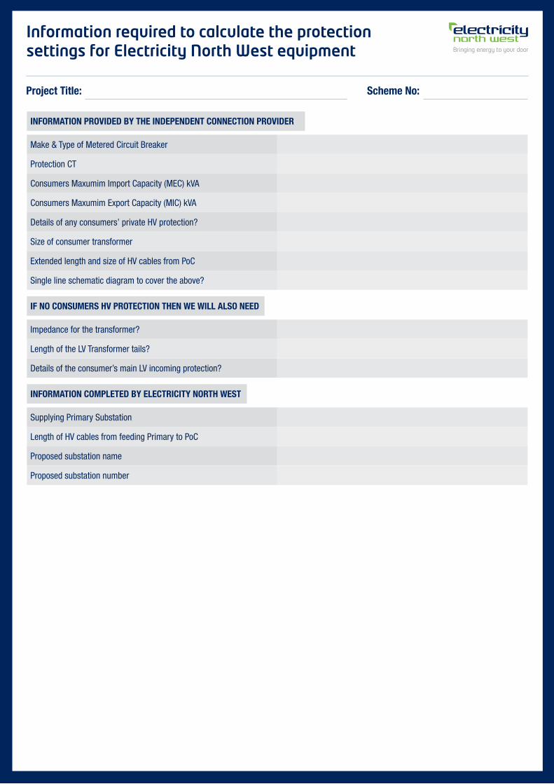
Information required to calculate the protection settings for Electricity North West equipment
Make & Type of Metered Circuit Breaker
Impedance for the transformer?
Supplying Primary Substation
Details of the consumer’s main LV incoming protection?
Proposed substation name
Length of the LV Transformer tails?
Length of HV cables from feeding Primary to PoC
Proposed substation number
Protection CT
Consumers Maxumim Export Capacity (MIC) kVA
Size of consumer transformer
Single line schematic diagram to cover the above?
Consumers Maxumim Import Capacity (MEC) kVA
Details of any consumers’ private HV protection?
Extended length and size of HV cables from PoC
Project Title: Scheme No:
INFORMATION PROVIDED BY THE INDEPENDENT CONNECTION PROVIDER
IF NO CONSUMERS HV PROTECTION THEN WE WILL ALSO NEED
INFORMATION COMPLETED BY ELECTRICITY NORTH WEST
Section 4 - LV Supplies from a Substation
PLEASE NOTE: This form MUST be completed in full (tick or add detail in each box as applicable). It will be used by Electricity North West Limited to check that all the necessary information has been included with your design submission. Any incomplete design submissions may lead to it being rejected with a request for the missing information.
4.1 Number & size of customer single core cables
4.2 Length of customer single core cables
4.3 Location of remote metering panel
4.4 HV/LV protection details
Section 5 - LV Networks
PLEASE NOTE: This form MUST be completed in full (tick or add detail in each box as applicable). It will be used by Electricity North West Limited to check that all the necessary information has been included with your design submission. Any incomplete design submissions may lead to it being rejected with a request for the missing information.
5.1 LV Schematic drawing showing proposed network and volt drop information
5.2 Phase colours for single phase supplies
5.3 Metering layout & equipment specification for central metering installations
5.5 LV & Transformer protection details
5.6 Metering arrangement details for any multi-occupied buildngs, as per ENWL policy ES287
5.7 Name of the Company who will act as the Building Network Operator (BNO)
5.4 Volt drop & earth loop impedance calculations to the most onerous points on the network (at least one calculation per LV Way out of a substation)
Section 6 - All Overhead Lines Installation
PLEASE NOTE: This form MUST be completed in full (tick or add detail in each box as applicable). It will be used by Electricity North West Limited to check that all the necessary information has been included with your design submission. Any incomplete design submissions may lead to it being rejected with a request for the missing information.
6.1 Pole specification (type/source of wood, height and girth)
6.2 Conductor specification (material & cross section)
6.3 Arrangement of pole top equipment (position & clearance)
6.5 Stay arrangements
6.6 Route survey results including ground clearances, visual impact, span lengths, section lengthy etc
6.7 Detailed location plan for the acquisition of legal consents
6.8 Risk assessment of location regarding dangers of accidental contact or damage by public. Details of any nearby structures, natural or man made etc
6.4 Ground conditions & pole foundation arrangements
Section 7 - Pole Mounted Transformers
PLEASE NOTE: This form MUST be completed in full (tick or add detail in each box as applicable). It will be used by Electricity North West Limited to check that all the necessary information has been included with your design submission. Any incomplete design submissions may lead to it being rejected with a request for the missing information.
7.1 Details of pole mounted equipment & specification
7.2 Details of any nearby structures, natural or man made etc
7.3 Fusing arrangements (HV & LV, sizes etc)
7.5 Transformer specification (maker, voltage, taps etc)
7.4 Earthing arrangements
For the attention of Address 1 Address 2 Address 3 Address 4
Tel: 0843 311 4351 [email protected]
Address 5 Address 6 01 January 2013
Dear Patrick
RE: Acceptance Of Outline Plan of Works, GM Waste, IVC Plant, Nash Road, Trafford Park.
I refer to your enquiry regarding the provision of a 1500 kVA connection to Electricity North West Limited system. From the information you have provided a scheme has now been prepared and the following Terms and Conditions are applicable which will also form the basis of a Connection Contract.
1 PROPOSAL To cater for your requirements it is necessary to supply this scheme from a new substation/cable to be connected to Electricity North West Limited existing High/Low Voltage system.
Connection Details
a) The Maximum Import Capacity will be **** kVA. b) The exit point will be the outgoing terminals of the 6.6/11kV HV metered
breaker OR LV metering panel. c) The voltage at the exit point will be 11,000 / 6600 / 400 volts, 3 phase. d) The earthing arrangement will be the responsibility of the customer. e) In addition to any advance connection charge payment you will also be
responsible for ongoing Use of System Charges in accordance with our published charging statement as amended from time to time. We will recover these from your electricity supplier who shall include them in their charges to you. For information, the current use of system charges that are likely to apply for this connection are given in our Use of System Charging Statement which can be found on our website ‘www.enwl.co.uk’. Where the charges include a Maximum Capacity component, the capacity can only be reduced after a period of 12 months from the supply availability date. If you do not commence, or cease to take energy through this exit point for any reason during this 12 month period, then the balance of the Capacity Charges shall become payable to us.
f) Please note, the use of the connection is covered by the ‘National Terms of Connection’ and details can be found at ‘www.connectionterms.co.uk’.
Metering I understand you have not nominated your Meter Operator.
2 TERMS
VAT Charges are shown exclusive of VAT at the appropriate rate. Conditions The terms are subject to the following site-specific conditions and Electricity North West Limited General Conditions of Contract, which can be viewed at http://www.enwl.co.uk/content/ourservices/electricityconnections.aspx.
1. These terms and Conditions are open for acceptance for a period of 30 days from
the date of this letter. Please note however, that this date is not a commitment to carry out the work by this date but is given purely as an indication of the current working programme for this type of work.
2. If there is any change to the information you have given it may be necessary to revise the scheme and adjust the terms accordingly.
3. A remote HV/modular LV metering panel will be supplied and installed by your Independent Connections Provider.
4. Large motors, welders or any other equipment likely to cause interference with
other customers cannot be connected without prior approval from Electricity North West Limited. Frequent start is more than one start in any consecutive 2 hourly period. If complaints arise as a consequence of failing to comply with the above, you will be required under these terms to disconnect the offending equipment. In addition, all costs attributed to any corrective work will be your responsibility.
5. The new installation will not be connected until a Wiring Completion Certificate is
received and satisfactory test results obtained.
6. We will not be responsible for permanently reinstating the surface of private land (including the surface of streets and pavements not adopted by the Highways Authority) after the cables have been installed.
7. That we are able to obtain, at no cost to us, all necessary legal consents for the work as planned.
8. When our work is completed you will be required to make arrangements to transfer all your existing circuitry to the new exit point for once established the existing one will be disconnected. However, until it is finally removed it must be treated as being “live”.
9. These Terms and Conditions relate up to the exit point only. They do not include any Contracting work on your installation.
10. That the load is balanced as far as practicable over the three available phases.
11. For as long as the equipment is connected to our system, we will require accommodation for Electricity North West Limited service apparatus and access to it for inspection, repairs and maintenance. If you wish us to relocate any of our apparatus this, if practicable, will be carried out at your expense.
12. Arrangements should be made to ensure that any standby generators cannot operate in parallel with our system. Where a generator is present, a drawing should be submitted for Electricity North West Limited approval showing the proposed method of electrical connection.
13. That we are able to carry out any work as planned. Any variations to these proposals must be agreed in writing with the site Construction Engineer, who will also arrange for any additional costs to be submitted to you.
14. That all work is undertaken during Electricity North West Limited normal working hours.
15. A metering point on Electricity North West Limited distribution system may not be energised unless an electricity supplier has registered with Electricity North West Limited to supply electricity at that point.
These Terms and Conditions form a contract. If they are acceptable to you, please sign and return the complete second copy of this letter and your completed ‘End User Questionnaire’. If a dispute arises which we cannot resolve, you can contact Energy Ombudsman at PO Box 966, Warrington, WA4 9DF, by telephone on 0845 055 0760 or online at www.energy-ombudsman.org.uk, who will assist in resolving the dispute. Yours faithfully, Alan Kemp Asset Adoption Engineer Electricity North West Limited
ACCEPTANCE (SCHEME TITLE) Please note that in this letter “you” and “your” refer to the user of the Exit Point, irrespective as to whether this correspondence is between Electricity North West Limited and the Users agent, or directly between Electricity North West Limited and the User. This is because acceptance of our terms could commit the user to the payments of a connection charge or the payment of Use of System Charges, or both. An agent may accept the terms on behalf of the user, in which case it is understood that the agent is acting with the full knowledge and consent of the user. It is strongly recommended that an agent obtains this authority in writing otherwise any outstanding Use of System Charges may be sought from the agent. I confirm that I have read these Terms and Conditions contained in this letter and the requirements attached and in consideration of Electricity North West Limited providing the Exit point, I have requested, and as described above, I agree to be bound by them. Signed........................................................... Date........................ Name ......................................................... Designation.............................. * Signed by user / agent (delete as appropriate) If by Agent then; - Company Name of User ......................................................................... Address of Registered Office ................................................................. ..................................................... ..................................................... ..................................................... Name of Agent ..................................................... Project No: ******** Scheme Title: – SCHEME TITLE METER OPERATOR I intend to appoint the following as my Meter Operator ............................................................................…….
(Acceptance continued –*******) ELECTRICITY SUPPLIER Under the 1998 Trading Arrangement a customer may choose to change his supplier at any time. However, it is important that you remain with the existing supplier for the premises during any alterations to achieve your increased supply capacity. If you subsequently decide to change your supplier please do not initiate this until after your increased supply capacity has been made available. As advised in previous correspondence, it is essential that you inform the present supplier of your intention to increase the agreed supply capacity. In accepting these terms and conditions it is deemed that you have done so. NOMINATION OF ELECTRICITY SUPPLIER In order to provide a connection to your premises I need to know who your nominated Electricity Supplier is; My nominated supplier is………………………………………………… PLEASE RETURN THE WHOLE OF THIS LETTER NOT JUST THE ACCEPTANCE PAGES. If calling please ask for Mr Alan Kemp
Declaration by the End User of SCHEME TITLE I agree to pay Availability Charges based upon a Maximum Import Capacity of xxxxxxxxxxx kVA for a minimum period of 12 months from the date the connection is energised.
****************
In addition to any advance connection charge payment, you will also be responsible for ongoing Use of System Charges in accordance with our published charging statement as amended from time to time. We will recover these from your electricity supplier who shall include them in their charges to you. For information, the current use of system charges that are likely to apply for this connection are given in our Use of System Charging Statement which can be found on our website ‘www.enwl.co.uk’. Where the charges include a Maximum Capacity component, the capacity can only be reduced after a period of 12 months from the supply availability date. If you do not commence, or cease to take energy through this exit point for any reason during this 12 month period, then the balance of the Capacity Charges shall become payable to us. Please note, the use of the connection is covered by the ‘National Terms of Connection’ and details can be found at ‘www.connectionterms.co.uk’.
Signed ……………………………………… Date…………………….…… On behalf of ……………………………………… ……………………………………… ……………………………………… Scheme No: xxxxxxxxx