Embed Size (px)
Citation preview

Design Summary Report For LaGalleria Goshen Office Complex
Item Type text; Electronic Thesis
Authors DiMurro, Miranda Jean
Publisher The University of Arizona.
Rights Copyright © is held by the author. Digital access to this materialis made possible by the University Libraries, University of Arizona.Further transmission, reproduction or presentation (such aspublic display or performance) of protected items is prohibitedexcept with permission of the author.
Download date 24/05/2018 14:34:36
Link to Item http://hdl.handle.net/10150/190440

CE 498 – Senior Capstone Spring 2008
Design Summary Report
for
La Galleria Goshen Office Complex
Submitted to: Mick Mathieu, P.E.
Submitted by: DRTM Lewis, LLC
May 6, 2008

DRTM Lewis, LLC La Galleria Goshen Project No. 08.400.237
Table of Contents
1.0 Executive Summary ....................................................................................... 1 2.0 Introduction .................................................................................................. 1
2.1 Project Narrative .................................................................................... 1 2.2 Project Objectives ................................................................................... 2
3.0 Zoning Code Modifications ............................................................................ 2
3.1 Required Modifications to Zoning Designation ............................................. 2 3.2 Current Zoning Classification .................................................................... 4 3.3 Regulatory Options ................................................................................. 4 3.4 Proposed Change to Zoning Classification ................................................... 4 3.5 Additional Necessary Zoning-Related Variances ........................................... 5
4.0 Geotechnical Engineering .............................................................................. 5
4.1 Scope of Services ................................................................................... 5 4.2 Geotechnical Investigation ....................................................................... 6 4.3 Existing Soil Conditions ............................................................................ 6 4.4 Soil Strength and Design Parameters ......................................................... 7 4.5 Selected Foundation Type ........................................................................ 8 4.6 Structural Loadings for Foundation Design .................................................. 8 4.7 Foundation Design .................................................................................. 8
4.7.1 Post-Tensioned Slab-on-Ground ...................................................... 8 4.7.2 Interior Spread Footings ................................................................ 9 4.7.3 Column to Foundation Connections .................................................. 9
4.8 Finished Floor Elevation .......................................................................... 10 4.9 Earthwork ............................................................................................. 10
5.0 Grading Plan ............................................................................................... 10
5.1 Grading Plan ......................................................................................... 10 5.2 Imported Fill ......................................................................................... 11
6.0 Hydrological Engineering ............................................................................ 11
6.1 Summary of Previous Work ..................................................................... 11 6.2 Detention Basin Sizing ............................................................................ 11 6.3 Additional Drainage Issues ...................................................................... 12 6.4 Overexcavation of Detention Basin ........................................................... 12 6.5 Vegetation ............................................................................................ 13
7.0 Traffic Engineering ...................................................................................... 14
7.1 Previous Analysis and Proposed Revisions ................................................. 14 7.2 Parking Requirements ............................................................................ 14 7.3 Generated Trips ..................................................................................... 15 7.4 Cortaro Farms Road and Thornydale Road Intersection Analysis ................... 16
8.0 Structural Engineering ................................................................................ 19
8.1 Introduction .......................................................................................... 19 8.2 Design Criteria ...................................................................................... 19 8.3 Load Analysis ........................................................................................ 19
8.3.1 Gravity Load Analysis ................................................................... 20
i

DRTM Lewis, LLC La Galleria Goshen Project No. 08.400.237
8.3.2 Lateral Load Analysis .................................................................... 20 8.3.3 Design Load Combinations ............................................................ 20
8.4 Member Design ..................................................................................... 20 8.4.1 Beam Design ............................................................................... 20 8.4.2 Girder Design .............................................................................. 21 8.4.3 Column Design ............................................................................ 21
8.5 Connection Design ................................................................................. 21 8.5.1 Moment Connection ..................................................................... 21 8.5.2 Shear Connection......................................................................... 21 8.5.3 Column Base Connections ............................................................. 21
8.6 Architectural and Structural Plans ............................................................ 22 8.6.1 Architectural Plans ....................................................................... 22 8.6.2 Structural Plans ........................................................................... 22
9.0 Project Summary......................................................................................... 26 10.0 References .................................................................................................. 27
Appendices Appendix A ....................................................................................... Scope of Services Appendix B ...................................................................................................... Zoning Appendix C ............................................................................................. Geotechnical Appendix D ................................................................................................. Hydrology Appendix E ........................................................................................... Transportation Appendix F .................................................................................................. Structural
ii
DRTM Lewis, LLC La Galleria Goshen Project No. 08.400.237
iii
Summary of Group Member Contributions The design group for DRTM Lewis, LLC consisted of seven members, each of whom had a specific focus area pertaining to the development of the site. Dave Newman prepared the sections of the project and report dealing with the site zoning and also geotechnical concerns, which consisted primarily of site soil classification and then design of the structure foundation. David Ruvalcaba and Jeffery Hunt prepared the sections pertaining to hydrology, which included the design of a retention/detention basin for the specified site and mitigation of several environmental issues. Jeffery Hunt also prepared the site grading plan. Michelle Bording and Tristan Nickel prepared the sections pertaining to transportation, including design of the parking layout, expected trip generation for the developed site, and analysis of an intersection impacted by the project. Taku Kojima worked alongside me in preparing the sections pertaining to structural design, which consisted of design of all structural members and connections, as well as the preparation of architectural and structural plans. In addition to the work on structural design, I served as the Principal of the group. My duties as Principal consisted primarily of organizing meetings, delegating tasks to different members of the group, and keeping track of the project progress. I also performed many small tasks which did not fall under any one discipline, including conducting final edits of all reports and presentations.
1.0 Executive Summary DRTM Lewis, LLC (DRTM Lewis) is pleased to present this Design Summary Report for the La Galleria Goshen Office Complex located at the southeast corner of the intersection of North Thornydale Road and Goshen Drive (the site). As requested by Mr. Mick Mathieu, P.E. (hereafter, Client), DRTM Lewis has completed the necessary design components for the development of the site for a proposed 24,000 square foot office building containing an integral restaurant/cafeteria. Furthermore, the office area includes a 30’ X 30’ X 30’ atrium in order to improve the aesthetics and present an attractive leasing opportunity for prospective tenants. The main areas of focus in completion of this project have been addressing shortcomings in the present zoning restrictions as they relate to the intended uses, completion of a site grading plan, design of hydraulic structures including a detention basin, complete design of the structure and foundation for the proposed office building, adjustment of required parking and trip generation figures as well as the analysis of the nearby intersection of North Thornydale Road and Cortaro Farms Road. The balance of this Design Summary Report contains the final designs necessary for the development for the site for the intended uses.
2.0 Introduction 2.1 Project Narrative The property subjected to this Design Summary Report is located within the unincorporated limits of Pima County, Arizona. More specifically, the site is situated in the NW ¼ of Section 29, Township 12 South, Range 13 East of the Gila and Salt River baseline and meridian. The property identified as Pima County Assessor Parcel Number (APN) 225-30-7130 has been slated for development by the Client, a local real estate developer. The site, comprising 2.95 acres, represents a portion of the area described as the Block 1 Commercial Area in the final plat of the east adjacent Cortaro Crossing residential subdivision. The official title of this project is identified as La Galleria Goshen, which is further described as an office complex. The Client has also requested that the La Galleria Goshen office complex include a cafeteria/restaurant to serve future tenants. The general project location and existing conditions are indicated on Figure 2.1.1 – Site Location Map and Figure 2.1.2 – Existing Site Conditions, respectively.
- 1 -

Figure 2.1.1. Site location map.
2.2 Project Objectives The specific scope of services requested by the Client requires that DRTM Lewis complete an amendment to the current zoning code that would allow the proposed uses, prepare a site grading plan, design the complete structural and foundation system for the building, address hydrological concerns including design of a retention basin, provide parking and trip generation figures as a result of the development and, finally, to provide analysis of the impact to the nearby major intersection of North Thornydale Road and Cortaro Farms Road. All of these objectives were to be met in the context of designing a 20,000 square foot office building that includes a 30’ x 30’ x30’ atrium and a 4,000 square foot restaurant or cafeteria. A copy of the complete project scope is provided as Appendix A.
3.0 Zoning Code Modifications 3.1 Required Modifications to Zoning Designation As described in the December 4, 2007, Preliminary Design Summary Report for La Galleria Goshen Office Complex and Retail Center prepared by DRTM Lewis, the proposed restaurant/cafeteria within the La Galleria Goshen office building is not compatible with the site’s current Pima County Zoning designation. Specifically, the project parcel is presently zoned as TR, which is identified in the Pima County Zoning Code as “Transitional.” Allowable uses within the TR classification do not include restaurants, which is an integral portion of the La Galleria Goshen design concept. As an initial mitigation strategy, DRTM Lewis recommended that a petition for a zoning change be submitted to Pima County Planning Division prior to the initiation of additional design or site work. A preliminary, completed version of an Application for Rezoning was included in the Preliminary Design Summary Report. That rezoning package requested a
- 2 -

change in zoning from TR to CB-1 (i.e. “Local Business Zone”), a classification that permits the operation of restaurants. However, at the request of the Client, instead of submitting a rezoning application DRTM Lewis has investigated what modifications would be necessary to adjust the existing TR classification to permit the incompatible use. 3.2 Current Zoning Classification A complete version of the current TR zoning classification is presented in Appendix B. As listed in Permitted Uses (18.31.010) section, restaurants are permitted only if they are associated with a hotel or motel. 3.3 Regulatory Options In order to determine the strategy most likely to result in a successful change to the present zoning code, DRTM Lewis investigated the various regulatory language used to permit restaurants throughout the present code. After completing this review, it seems that food service establishments are permitted in one of three manners: (1) Directly Permitted Use, (2) Associated/Secondary Use or (3) Conditional Use. During development of the existing code, Pima County undoubtedly considered permitting restaurants within the TR classification. The resulting exclusion of food service establishments from the TR designation implies that the Pima County Planning Division did not believe that it was beneficial to allow restaurants essentially without restriction. As a result, DRTM Lewis does not believe that pursuing a zoning change to allow restaurants as Directly Permitted Uses will meet with success. Allowance of food service establishments as Associated or Secondary Uses is a possibility. In fact, restaurants are currently permitted within the TR designation if they are associated with a hotel or motel. However, based on the relatively flexible design concept of La Galleria Goshen in terms of possible tenants, DRTM Lewis believes that it may be risky to pursue this permitting avenue. Doing so exposes the Client to the potential that the anchor usage no longer leases space at the site, thereby eliminating the possibility of maintaining food service. As a result, DRTM Lewis recommends that the Client pursue a change to the current TR designation by modifying the code to allow food service establishments as Conditional Uses. In the opinion of DRTM Lewis, making a change to the current zoning code in this manner is the most likely to meet with success. As a Conditional Use, the Pima County Planning Division is allowed to exercise discretion over the projects that it deems appropriate. In contrast, modifying the existing language in any other manner removes the Planning Division from the decision making process. 3.4 Proposed Change to Zoning Classification As described above, DRTM Lewis proposes that the Client pursue a modification to the Conditional Uses (18.31.020) section of the TR zoning classification. A complete version of the altered zoning code is presented as Appendix B. However, for convenience, both the existing and proposed modified language for the Conditional Use section are presented below.
Table 3.4.1. Current language in Section 18.31.020 of the TR Zoning classification. 18.31.020 Conditional Uses
Reserved.
- 4 -

Table 3.4.2. Modified language to Section 18.31.020 of the TR Zoning classification. 18.31.020 Conditional Uses
A. The following uses, not identified in Section 18.31.010, are permitted as conditional Type II uses, except as otherwise specified, subject to the procedures as set forth in Chapter 18.97 (Conditional Use Procedures): 1. Bakery; 2. Cafe or lunchroom:
a. Provided no dancing is allowed and no alcoholic beverages sold except beer and wine,
b. The "patio" architectural design concept is allowed; 3. Catering service; 4. Restaurant or tea room; in connection therewith:
a. Provided such use is accessory to an office complex. b. But not to include drive-in restaurants.
B. A conditional use permit is not required for a property that is approved for a rezoning to the CB-1 zone (or more permissible) with a list of use limitations.
3.5 Additional Necessary Zoning-Related Variances Thornydale Road is identified as a Major Scenic Route within Pima County. As a result, the site is impacted by the Section 18.77.040 Scenic Routes provisions in the Pima County Code. An additional building setback burden of 30 feet plus half of the right of way is required, along with an additional height restriction that limits that maximum height of commercial buildings to 24 feet within 200 feet of the property line. The Scenic Routes provisions also affect allowable signage and building exterior paint colors, which are concerns as the development of the North and South parcels progresses towards completion. The building setback, allowable signage and building exterior paint colors have either already been mitigated during completion of this design, or are relatively minor and do not significantly impact the project. However, based on the Client’s request for an atrium measuring 30 feet high in the office building, a variance to the height restriction imposed by the location of La Galleria Goshen within 200 feet of a Major Scenic Route Corridor is required. At present, the restriction is set at 24 feet. At the request of the Client, DRTM Lewis has designed La Galleria Goshen with a building height of approximately 34 feet. DRTM Lewis has been advised by the Client that the necessary Major Scenic Route Corridor variance will be granted at his request. As a result, DRTM Lewis assumes no liability in the event that the variance is not granted.
4.0 Geotechnical Engineering 4.1 Scope of Services The purpose of the geotechnical portion of this report is to outline the design of the foundation system for the La Galleria Goshen project. The information on which this design is based was presented in the December 4, 2007, Preliminary Design Summary Report for La Galleria Goshen Office Complex and Retail Center prepared by DRTM Lewis. Nevertheless, some of that information is presented in summarized form within this report to aid in understanding of the foundation design.
- 5 -

4.2 Geotechnical Investigation A preliminary soil investigation was performed in August 2003, by Western Technologies Inc. (Western Tech). Boring logs from that investigation were made available to DRTM Lewis by the Client. The investigation included the advancement of 11 soil borings and four infiltration test locations using a CME-55 drilling rig equipped with hollow stem augers. The purpose of the investigation was to gain insight into the general subsurface conditions within the confines of the Cortaro Crossing subdivision (Lots 1-135) and its associated Block 1 Commercial Area, of which parcels 225-30-7120 (North Parcel) and 225-30-7130 (South Parcel) are included. The acreage of the total investigated area is approximately 35.69, with the Block 1 Commercial Area comprising approximately 5.25 acres of that total. Soil boring logs and a summary of analyzed soil properties are presented in Appendix C. As a general rule, a minimum of two geotechnical borings should be advanced within the footprint of a proposed structure, with the number of borings increasing with the size of the structure and the types of soils encountered. An industry standard is a maximum boring spacing of 200 feet [Post-Tensioning Institute, 2004]. Spacing between the borings advanced by Western Technologies range between approximately 350 to 650 feet, and none of the borings were advanced within the proposed building footprint. Moreover, it is imperative that geotechnical information be collected from as many samples as possible to allow safe and economical design of the required foundation. In the absence of accurate or characteristic data, it is likely that the foundation design will require large factors of safety that will increase the cost of the foundation. Of the 11 total borings and four infiltration test pits advanced by Western Tech, three borings (B-5, B-6 and B-7) and one infiltration test pit (I-4) are located within the confines of the North and South Parcels. The relevant soil boring locations are presented in Appendix C. Due to this lack of information, DRTM Lewis performed an interpolation between borings B-5, B-6 and B-7 and infiltration test pit I-4 to estimate the subsurface conditions at the site. The interpolated geological cross sections are presented in Appendix C. However, due to the inherent variability of soils, DRTM Lewis makes no guarantee that such soil conditions actually exist beneath the proposed structure. As a result, DRTM Lewis recommends that a qualified individual be present at the time of the foundation excavation and construction to ensure that subsurface conditions do not vary significantly from the assumed soil conditions, or that a second geotechnical investigation be conducted once the location of the proposed structure is finalized. 4.3 Existing Soil Conditions Based on the soil borings logs and the interpolated geological cross sections, the subsurface is characterized by silty sand (Unified Soil Classification System [USCS]: SM) from the surface to depths ranging between five to 15 feet below ground surface (bgs), which is then underlain by a poorly sorted sand (USCS: SP) ranging from five to 21.5 feet bgs. The maximum depth of exploration was 21.5 feet bgs. All of the boring logs indicate increasing soil density and prevalence of gravel and cobbles with increasing boring depth. Groundwater was not encountered in any of the soil borings and evidence of a seasonally-high groundwater table (e.g. mottling) was not noted in any of the boring logs. Physical soil properties were collected for two samples from borings B-5 and B-6. In addition, one near-surface sample from each boring was subjected to limited laboratory analysis to investigate the potential for settling. In each sample, significant (>5%) compression was noted when loads equal to or greater than 1500 psf were applied. Additionally, the soils indicated potential for collapse when saturated, with percent
- 6 -

compression reaching a maximum of 12% (Appendix C). Table 4.3.1 includes selected soil properties as well as typical ranges for similar soil types. Table 4.3.1 Selected soil properties for samples collected during the August 2003 investigation.
Boring Sample Depth
Soil Type Dry Unit Weight
Moisture Content
Bearing Capacity
CBR Value Subgrade Modulus, k
[ft bgs1] [] [lbs/ft3] [%] [lb/ft2] [] [lbs/ft3] B-5 1.5-2.5 SM 107 2.2 --- --- --- B-5 5.0-6.0 SM 118 2.1 --- --- --- B-6 2.0-3.0 SM 111 1.8 --- --- --- B-6 5.0-6.0 SM 116 2.5 --- --- --- Range of Typical Values2 for SM 110-1253 11-164 1050 10-40 200-300
Notes: 1 – Below ground surface. 2 – Adapted from reference [1].
3 – Range of dry unit weights after compaction. 4 – Moisture contents when compacted in accordance with standard proctor analysis.
Information regarding the infiltration rate for test pit I-4 was not made available to DRTM Lewis. As a result, DRTM Lewis converted the USCS soil classifications to the US Department of Agriculture (USDA) soil classification system and utilized the Arizona Aquifer Protection Permit (APP) septic system design criteria for soil application rates (SARs) to estimate the infiltration capacity of the soil. The SM soil converted to a Loam/Sandy Loam/Sandy Clay Loam and the SP soil became Sand in the USDA system, with each yielding an infiltration rate in excess of 100 minutes per inch (mpi). Due to the composition of septic effluent and its effect on seepage, it is likely that the actual infiltration rate is significantly faster than 100 mpi. An alternate resource consulted to assess the infiltration capacity (in the absence of percolation test data) was the USDA Web Soil Survey. According to the soil data, the South Parcels possesses soils that have a low potential for surface ponding and are generally considered well-drained. Additionally, the City of Tucson Detention and Retention Manual indicates that the project location is situated in a region of soils with good infiltration capacities. 4.4 Soil Strength and Design Parameters The soil information collected by Western Tech and presented in Appendix C does not provide insight into the various measures of soil strength required for foundation design. As a result, DRTM Lewis employed the empirically-based method of estimating soil parameters based on the blow count (N) required to advance a split-spoon sampler six inches into the sampled soil strata. At a depth of five feet in boring B-5, an N value of eight corresponds to a loosely compacted coarse-grained material [2]. A typical relative density (an index of the degree of packing between the loosest and densest soil) for such a material is 30% with a generic friction angle between 29 to 34 degrees [2]. Based on potential for collapse at loads greater than 3000 pounds per square foot (psf), DRTM Lewis designed the foundation on the basis that the net allowable bearing pressure of the soil beneath the foundation should not exceed 2000 psf. This is in accordance with an allowable bearing capacity of 2000 psf for SM and SP soils in the 2006 edition of the International Building Code [3]. The lateral sliding resistance coefficient of friction is 0.30 per Pima County Building Code ordinance 18.04.3.2. The allowable level of differential settlement was established based on the most stringent criteria (aesthetic considerations as opposed to structural capacities). As a result, the
- 7 -

allowable level of differential settlement will be 0.75 inch, with a total allowable uniform settlement of 1.0 inch. 4.5 Selected Foundation Type Inspection of the limited geotechnical data available for the site indicates a potential for collapse in the SM material. However, due to requirements that the site be raised above the 100-year water surface elevation in the adjacent wash, a significant quantity of fill will be required to raise the site’s elevation. In some areas, the depth of imported fill will approach five feet. Due the fact that bearing on the foundation will decrease with depth, DRTM Lewis believes that the potential for collapse in the soil will have been effectively mitigated by the importation of so much fill. However, because this foundation design is based on such a limited geotechnical investigation, DRTM Lewis still recommends that La Galleria Goshen be supported with a post-tensioned (PT) slab-on-ground foundation. A PT foundation is still necessary because it will effectively bridge areas of potentially poor quality soil and prevent excessive or differential settlement. However, due to the loads presented by the structural system, the interior columns will also be supported by spread footings to prevent shear failure in the PT slab. 4.6 Structural Loadings for Foundation Design The final column layout of the proposed structure includes 24 columns. Of the 24 columns, there are three major types including corner, exterior and interior columns. The maximum axial compressive loading of each column type is 47.2 kips (k), 113.1 k and 317.5 k for corner, exterior and interior columns, respectively. Each of the column-to-slab connections were designed as pinned connections and, as a result, the column connections do not need to transmit moment to the subsurface. In order to simplify the construction of this foundation and provide an inherent factor of safety in the design, the foundation design is based on the maximum axial loadings of each column type, despite the fact that some of the columns indicate significantly lower axial loadings. 4.7 Foundation Design 4.7.1 Post-Tensioned Slab-on-Ground During the design of a PT foundation, the first iteration is to develop a slab that utilizes ribs, or subsurface beams, to support the structure’s loads. Depending on the application, the second iteration is to transform the ribbed foundation into a slab of uniform depth. A uniform depth slab greatly simplifies the construction of PT foundations. Due to the relatively large size (140’ x 85’) of the PT foundation in this project, DRTM Lewis chose to design a uniform thickness slab. The complete design of the PT foundation was completed in strict accordance to the third edition of the Post-Tensioning Institute’s (PTI) Design of Post-Tensioned Slabs-on-Ground [4]. The first design iteration for the La Galleria Goshen Office Complex foundation determined the “slab and rib” geometry of a conventional PT foundation. In the ribbed foundation configuration, thickened concrete beams run both longitudinally and laterally, creating a grid of beams. The designed ribbed foundation indicated expected performance of differential settlement 0.11” and deflection of 0.49”, both of which are within design specifications. Figure 4.7.1.1 indicates a cut in a ribbed foundation based on implementation of the PTI design methodology.
- 8 -

Figure 4.7.1.1. Typical cut from the La Galleria Goshen ribbed PT foundation.
However, ribbed foundations present challenges during constructability due to their complex geometry and placement of reinforcing tendons. As a result, DRTM Lewis transformed the ribbed foundation into a uniform thickness foundation with the same expected design performance. By way of summary, the uniform thickness PT foundation will be 10 inches thick with ½” diameter, 270 ksi low relaxation tendons (i.e. reinforcement) spaced at 3 feet on center across the short width (85 feet). The long direction (i.e. 140 feet) will include ½” diameter, 270 ksi low relaxation tendons (i.e. reinforcement) spaced at 2 feet on center. The minimum edge distance from the edge of the slab for all tendons shall be 2 feet and the prestress applied to all tendons shall be 48 ksi (24 k). Figure 4.7.1.2 depicts the uniform thickness PT foundation.
Figure 4.7.1.2. Uniform thickness PT foundation. Tendon spacing is 24” on center in the long direction and 36” on center in the short direction. Calculations used to design the PT foundation for the La Galleria Goshen project are presented in Appendix C. 4.7.2 Interior Spread Footings The interior columns require additional support beneath the PT slab in order to prevent shear cone failure at the column-to-slab connections. This results in a thickening of the concrete directly beneath each interior column measuring 38 inches square. The thickness of this spread footing shall be 9 inches with no additional reinforcement, making the total thickness of the concrete beneath the interior columns 19 inches. These footings shall be placed at the same time as the PT slab, ensuring no failure surface between the slab and the footing. Spread footings are not required beneath the corner or exterior columns. Calculations used to design the spread footings are presented in Appendix C. 4.7.3 Column to Foundation Connections Design of the base plates connecting columns to the PT foundation is completed in Section 8.5.3 of this Design Summary Report. However, the physical connection of the base plate to the foundation will be achieved using the Simpson Anchor Systems® Titen HD Heavy Duty Screw Anchor System for Concrete. Specifically, the four anchor bolts shall be ½” diameter with an embedment depth of 5 ¾” based on the Simpson design tables. A copy of the Simpson Anchor Systems® Titen HD design tables are presented in Appendix C.
- 9 -

4.8 Finished Floor Elevation In accordance with section 1803.4.1 of the Pima County Building Code, the finished floor elevation (FFE) of any structure must be set at a minimum of one foot above the predicted 100-year water surface elevation (WSE). In its present, unimproved condition, the site grade is within the 100-year floodprone boundary. As a result, imported fill is required to raise the site’s elevation above the 100-year WSE. Projected 100-year WSE’s are depicted in Figure 2.2.2. As described in the Preliminary Design Summary Report, a Letter of Map Revision (LOMR) is pending with both Federal Emergency Management Agency (FEMA) and Pima County Flood Control District (PCFCD). The 100-year floodprone boundary specified the pending LOMR coincides with the construction of bank protection along the eastern property line of the site. Bank protection requires at least one foot of freeboard above the 100-year WSE to account for wave action. Because it is also necessary to provide positive drainage (minimum 2%) away from the foundation, it is probable that the FFE will be at an elevation in excess of the one foot requirement. Based on the projected 100-year WSE and the one-foot freeboard requirement, DRTM Lewis has established the FFE to be 2345.85 feet above mean sea level (amsl). 4.9 Earthwork Due the presumed presence of collapsible soils in the area of the proposed structure on the South Parcel, DRTM Lewis recommends that the building footprint plus an additional five feet in all directions be over-excavated and replaced with engineered fill material. The fill will significantly improve the engineering properties of the subsurface and reduce the likelihood of collapse in the bearing soils. The over-excavation will be advanced to a minimum depth of three feet beneath the bottom of the PT foundation. The replacement material shall be engineered to meet the bearing capacity requirements once compacted to a minimum of 95% of the maximum dry density indicated by a standard proctor test. More specifically, DRTM Lewis requires that the fill be classified as Well Graded Sand (SW) with a maximum clay content of 5% and a minimum bearing capacity of 2000 psf. Based on the limited subsurface information, DRTM Lewis recommends that a competent geotechnical engineer be present at the time of the foundation excavation to ensure that subsurface conditions do not vary significantly from the assumed soil conditions.
5.0 Grading Plan 5.1 Grading Plan The creation of Grading Plan in accordance with Pima County standards is beyond the scope of this Design Summary. It is anticipated that completion of the final grading plan may represent a significant revision of the required volume of imported fill. The controlling parameter when grading this site is the WSE during the 100-year design storm event. Pima County Flood Control District requires that the proposed FFE is at least one foot above the WSE in the nearest water body in the vicinity of the site. For the La Galleria Goshen project, the controlling water body is the unnamed natural wash adjacent to the site along the eastern property line. In particular, the point of interest is the WSE at a location directly adjacent to the site of the proposed building pad.
- 10 -

Using the 100-year WSE, the FFE can be established. Once the FFE is established, the remainder of the site can be graded. According to regulations set out by the Americans with Disability Act (ADA), as well as guidelines set forth by the City of Tucson Land Use Code (LUC), slopes on the site are limited to values between 0.5% and 6%. The 0.5% minimum pertains to the limits of constructability. A preferred minimum is actually 1%, and as is illustrated on the Grading Plan, any 0.5% slopes must contain a concrete swale to prevent the “bird bath” effect, which results in standing water. ADA requires that all areas of handicap circulation are limited to a max slope of 2%, and the grading plan for La Galleria Goshen satisfies this requirement. Further, no grades exist in excess of the 6% maximum suggested by the LUC. The completed grading plan is included in the map pocket with this Design Summary Report. 5.2 Imported Fill To meet the conditions of the LOMR as well as Pima County Building codes, the site will require a maximum depth of imported material of seven feet. Comparing the grading plan with the existing conditions, DRTM Lewis estimates that development of the site will require approximately 16,500 cubic yards of fill.
6.0 Hydrological Engineering 6.1 Summary of Previous Work The site is bordered to the north by Goshen Drive, to the west by an improved, gunite-lined drainage channel in the North Thornydale Road right-of-way (ROW), and to the east and south by a regulatory wash (i.e. draining more than 20 acres). The natural, unnamed wash is classified by PCFCD as reaching a peak discharge between 500 and 1000 cubic feet per second (cfs) and clips the eastern and southern portions of the site. However, due to proposed construction of bank protection in accordance with the LOMR, this unnamed wash will no longer intrude upon the site. The result of the existing improvements to the north and west along with the proposed bank protection and fill import is that the site defines its own individual drainage area. As a result, the watershed limits of the site are essentially the site boundaries with a watershed area determined to be 3.2 acres. The determination of all site hydrological data was generated through use of the publicly-available software program entitled PC Hydro. The return period for the design is a 100-year storm event with 24 hour duration, with precipitation data obtained from National Oceanographic and Atmospheric Administration (NOAA) maps for Pima County. Other watershed- and site-specific parameters used as inputs in the PC Hydro program were generated from AutoCAD files provided to DRTM Lewis by the Client as well as Pima County’s online GIS system (i.e., MapGuide). The stormwater flow for the site prior to development was calculated as 18.8 cubic feet per second (cfs), which, based on the storm duration, indicates an existing runoff volume of 17,772 cubic feet (ft3). The flow for the South Parcel after build out was calculated as 25.9 cfs, which, based on the storm duration, indicates a runoff volume of 24,451 ft3. As a result, an excess of 6,679 ft3 of stormwater will be generated due to site improvements. 6.2 Detention Basin Sizing The volume of the Detention basin has to accommodate the increase in runoff volume. In addition, it is imperative to account for long-term sedimentation of the basin and the turbulent flow regime that will undoubtedly exist during the design storm event. As a
- 11 -

result, additional volume was added to account for sedimentation and an additional 0.5 foot of freeboard was added to the top of the basin. As a result, the top of the basin will be one-half foot higher than the 100-yr WSE in the vicinity of the basin. The calculated increased runoff volume was multiplied by a safety factor of 1.3. A typical safety factor according to the Pima County Hydrology Manual is 1.2, while the additional 0.1 is to account for sedimentation. Therefore, the minimum design volume of the basin for the site is 8,683 ft3. Based on the proposed detention basin geometry, 9,031 ft3 shall be provided. In order to provide assurance that the basin sizing is correct, the hydrologic data was analyzed in HydroCAD. HydroCAD is a basin routing program that utilizes elementary basin routing equations as a means of evaluating basin performance. The inputs are the Q values for the 100-yr design storm, the discharge of the basin through the weir and bleed pipes and the size of the basin. The output is the variable height inside the basin. Based on the HydroCAD analysis, the maximum water depth within the basin is 2.46 feet. The total depth is 2.50’ and the 2.46’ has accounted for the previously mentioned safety factors, thus, the size of the designed basin is sufficient for the 100-yr design storm. HydroCAD data and output is presented in Appendix D. 6.3 Additional Drainage Issues Due to recent concerns regarding the introduction of the mosquito-borne West Nile Virus, Pima County has adopted a strategy of discouraging the development of retention basins. Instead, Pima County has been encouraging the design of detention basins that drain entirely within a period of 24 hours, such that standing water does not develop and provide an opportunity for mosquito larvae to mature. To accommodate this concern, DRTM Lewis has provided an 18-inch polyvinyl chloride (PVC) bleed pipe with a 6” orifice plate on the intake to meter the water at rate between one and two cfs. At one cfs, 84,000 ft3 of water will drain in a 24-hour period, providing a large factor of safety against potential ponding in the detention basin. Additional drainage issues include 404 mitigation, disturbance of riparian habitat and the potential for site-generated runoff to increase the pollutant load downstream of the site. As a precursor to the development of the site, 404 mitigation was completed during the final platting of the Cortaro Crossing subdivision to the east. In terms of increased pollutant as a result of site improvements, it is likely that pollutants are will be detained in the basin as its generally quiescent conditions will allow the sediment and adsorbed pollutants to settle on the basin floor. 6.4 Overexcavation of Detention Basin The Pima County design manual for detention and retention basins does not require over-excavation to encourage infiltration of stormwater. The manual does, however, indicate that some retention/detention basins may be designed to encourage subsurface disposal, with the most common employed method being drywells. If the design engineer chooses to design the basin for subsurface disposal, another common method is the use of an Engineered Basin Floor (EBF). An EBF underlies the detention basin with a filter fabric, a sand layer and coarse gravel layer before returning to native material. Figure 6.4.1 depicts a typical cross section of an EBF.
- 12 -

Figure 6.4.1. Typical Engineered Basin Floor (EBF) Cross Section.
The decision to design for subsurface disposal is at the discretion of the engineer. However, PCFCD does require that positive drainage is provided from the detention basin to prevent the development of standing water. As detailed, the proposed detention basin provides a minimum of 0.5% slope towards the bleed pipe from all areas of the basin. The presence of the bleed pipe ensures that standing water will not remain in the basin. Moreover, soil data for the project area indicates that the site possesses native soils that have a low potential for surface ponding (i.e. standing water) and are generally considered well-drained. As a result, DRTM Lewis believes that designing an EBF in conjunction with positive drainage, a bleed pipe and well-drained native soils is excessive and not required. 6.5 Vegetation The intended size of the proposed office building required that that building setback along North Thornydale Road be reduced to 25 feet. Coupled with the fact that the project site is located within a Major Scenic Road Corridor and is zoned as Transitional, landscaping for the site must be completed in accordance with the requirements of Bufferyard D. Bufferyard D is described in the Pima County Landscape Design Manual as undisturbed natural desert plants and grasses at locally-occurring densities. Specifically, Bufferyard D requires ten canopy trees, ten shrubs and 15 accents, flowers or vines per 100 linear feet. The Bufferyard D requirements are necessary along site’s boundary with North Thornydale Road, which is approximately 550 feet long. In addition, the plant unit multiplier is used to adjust the number of plants based on the bufferyard width. In the case of a 25 foot Buffeyard D, the plant unit multiplier is 0.40. As a result, 22 canopy trees, 22 shrubs and 33 accents, flowers or vines will be required for the buffer area. Selected canopy trees shall include 11 Mesquites and 11 Foothills Palo Verdes. Eight Chuparosas, seven Coral Bean and seven Red Baja Fairydusters will complete the shrub requirement, while eight Mexican Agave, eight Prickly Pears, eight Ocotillos and seven Desert Spoons will be used to meet the minimum of 33 accents, flowers or vines. In addition, eight Mesquites and eight Foothills Palo Verdes will be used throughout the site in the designated landscape areas. The designated open/picnic area shall include an additional four Foothills Palo Verde trees to provide shade. Moreover, the small concrete stormwater channel from the parking lot to the detention basin shall be lined with three Mesquites, four Chuparosa and three Coral Beans. The detention basin will also be screened by Chuparosa and Coral Bean bushes. The detention basin interior will include four Foothill’s Palo Verde trees and it will also be hydro-
- 13 -
seeded. The side slopes of the basin will also be hydro-seeded to prevent potential erosion damage.
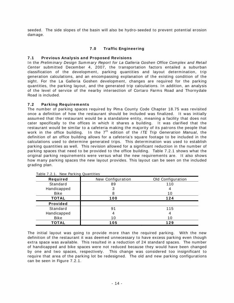
7.0 Traffic Engineering 7.1 Previous Analysis and Proposed Revisions In the Preliminary Design Summary Report for La Galleria Goshen Office Complex and Retail Center submitted December 4, 2007, the transportation factors entailed a suburban classification of the development, parking quantities and layout determination, trip generation calculations, and an encompassing explanation of the existing condition of the sight. For the La Galleria Goshen development, changes are required for the parking quantities, the parking layout, and the generated trip calculations. In addition, an analysis of the level of service of the nearby intersection of Cortaro Farms Road and Thornydale Road is included. 7.2 Parking Requirements The number of parking spaces required by Pima County Code Chapter 18.75 was revisited once a definition of how the restaurant should be included was finalized. It was initially assumed that the restaurant would be a standalone entity, meaning a facility that does not cater specifically to the offices in which it shares a building. It was clarified that the restaurant would be similar to a cafeteria making the majority of its patrons the people that work in the office building. In the 7th edition of the ITE Trip Generation Manual, the definition of an office building allows for a cafeteria’s square footage to be included in the calculations used to determine generated trips. This determination was used to establish parking quantities as well. This revision allowed for a significant reduction in the number of parking spaces that need to be provided to the office building. Table 7.2.1 shows what the original parking requirements were versus what the new requirements are. It also shows how many parking spaces the new layout provides. This layout can be seen on the included grading plan.
Table 7.2.1. New Parking Quantities
Required New Configuration Old Configuration Standard 89 110
Handicapped 3 4 Bike 8 10
TOTAL 100 124 Provided Standard 91 115
Handicapped 4 4 Bike 10 10
TOTAL 105 129 The initial layout was going to provide more than the required parking. With the new definition of the restaurant it was deemed unnecessary to have excess parking even though extra space was available. This resulted in a reduction of 24 standard spaces. The number of handicapped and bike spaces were not reduced because they would have been changed by one and two spaces, respectively. This change was considered too insignificant to require that area of the parking lot be redesigned. The old and new parking configurations can be seen in Figure 7.2.1.
- 14 -

Figure 7.2.1. Original and revised parking layouts for La Galleria Goshen.
7.3 Generated Trips Similar to the need for the reevaluation of parking quantities as a result of the restaurant area being included in the office building definition, the trips generated by the new development needed to be recalculated as well. This was accomplished by using the same calculations that were performed previously for the general office building only with a square footage that was increased by 4000 sq ft (the area of the restaurant). The equations used for daily, AM Peak Hour, and PM Peak Hour trips are listed as Equations 7.3.1, 7.3.2, and 7.3.3, respectively and can be found in the 7th edition of the ITE Trip Generation Manual. ln(T) = 0.77ln(x) + 3.65 (7.3.1) ln(T) = 0.80ln(x) + 1.55 (7.3.2) T = 1.12x + 78.81 (7.3.3) Where: x = Square footage/1000 of the building fitting the definition
T = Trips generated
The resulting trip values calculated for a 24,000 sq ft general office building can be found in Table 7.3.1.
- 15 -

Table 7.3.1. New Trip Calculations
New Configuration Old Configuration
General Office Building General Office Building + High Turnover Restaurant
Daily 445 891 AM Peak Hour 60 107 PM Peak Hour 106 176
7.4 Cortaro Farms Road and Thornydale Road Intersection Analysis When analyzing the intersection of Cortaro Farms Road and Thornydale Road, traffic counts and revised trip calculations were required. The counts were taken during two hour blocks: one from 7:00 to 9:00 AM and the other from 4:00 to 6:00 PM. Counts were recorded for each fifteen minute interval. From these counts the peak hour and peak fifteen minutes were found. Once determined they were entered into HCS Plus software along with the signal timing and intersection layout parameters. HCS provided the level of service (LOS) for each approach and the intersection as a whole. The next step was to inflate the counts and make any adjustments in order to see how the developed condition will affect the intersection. The design year was 2010 for all intersection analysis purposes. When projecting the collected trip values, all turning count ratios were unchanged. For example, if fifty-eight percent of the north bound vehicles were through movements in the counts conducted in 2008, fifty-eight percent of northbound vehicles were through movements in the counts inflated to reflect 2010 values. When incorporating the trips generated by La Galleria Goshen, the assumption that fifty percent of the trips were associated with any northward street system and that fifty percent were associated with any southward street system. As a result, this indicates that only half of all calculated trips generated by the new development will be used in the HCS analysis of the intersection of Cortaro Farms Road and Thornydale Road. Generated trip counts were also applied in a proportionate manner that was consistent with the turning ratios observed during the turning counts in 2008. The turning counts observed and entered into the HCS software for an analysis of the current conditions as well as the projected turning counts that include the trips generated by the new development can be found in Table 7.4.1. A complete table of the turning counts as well as the adjusted values for the 2010 design year can be found in Appendix E. Table 7.4.1. Current and Future Turning Movement Counts
AM Peak Hour PM Peak Hour
Direction Turning
Movement
2008 Volume (vph)
2010 Volume (vph)
2008 Volume (vph)
2010 Volume (vph)
Eastbound Left 222 240 300 324
Through 402 435 460 498 Right 143 170 174 195
Westbound Left 146 162 115 129
Through 255 276 440 476 Right 89 96 108 117
Northbound Left 106 115 330 358
Through 386 420 623 676 Right 50 54 129 140
Southbound Left 164 177 203 220
Through 586 651 463 519 Right 193 209 205 222
- 16 -
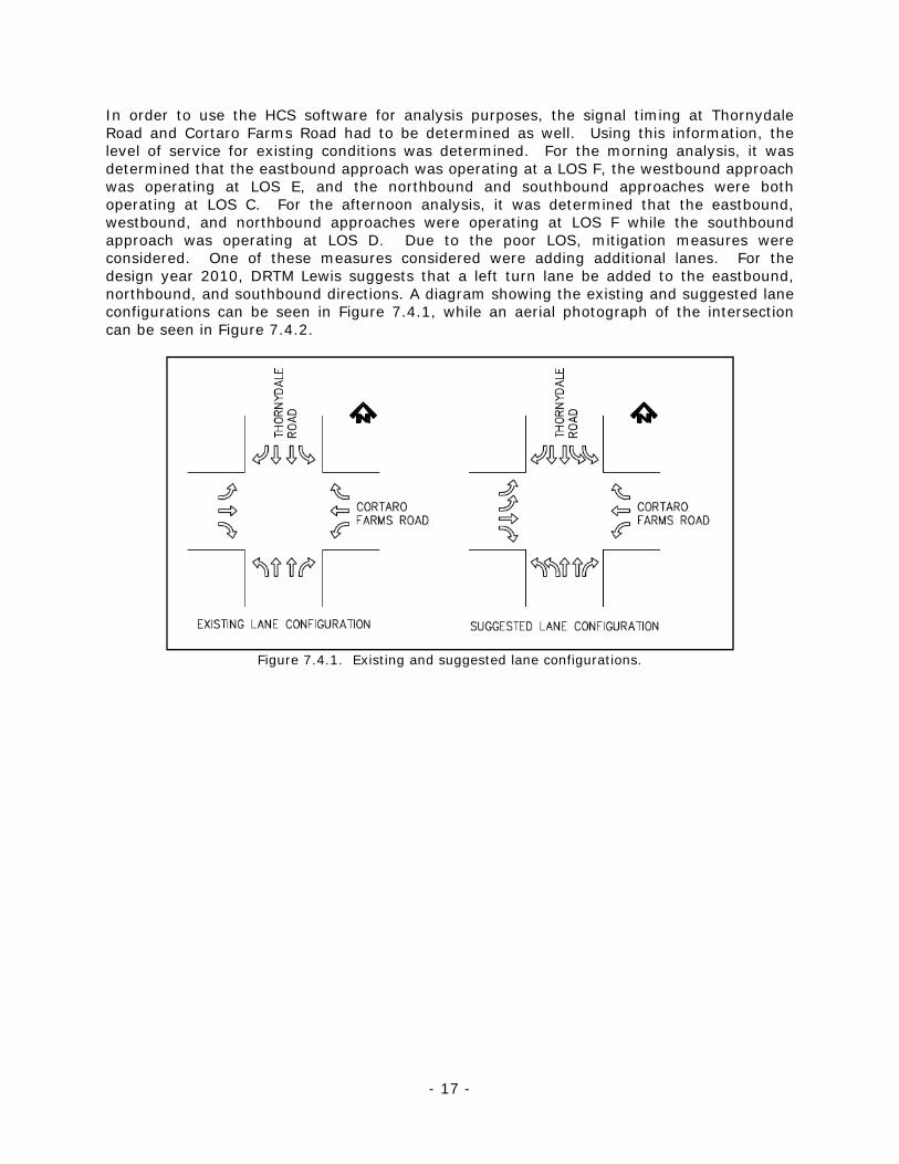
In order to use the HCS software for analysis purposes, the signal timing at Thornydale Road and Cortaro Farms Road had to be determined as well. Using this information, the level of service for existing conditions was determined. For the morning analysis, it was determined that the eastbound approach was operating at a LOS F, the westbound approach was operating at LOS E, and the northbound and southbound approaches were both operating at LOS C. For the afternoon analysis, it was determined that the eastbound, westbound, and northbound approaches were operating at LOS F while the southbound approach was operating at LOS D. Due to the poor LOS, mitigation measures were considered. One of these measures considered were adding additional lanes. For the design year 2010, DRTM Lewis suggests that a left turn lane be added to the eastbound, northbound, and southbound directions. A diagram showing the existing and suggested lane configurations can be seen in Figure 7.4.1, while an aerial photograph of the intersection can be seen in Figure 7.4.2.
Figure 7.4.1. Existing and suggested lane configurations.
- 17 -

Figure 7.4.2. Aerial photograph of the Intersection of Thornydale Rd and Cortaro Farms Rd.
Also, signal timings should be changed in accordance with Table 7.4.2. This table shows existing signal timings that were used for the existing conditions analysis of the intersection as well. Table 7.4.2. Suggested Signal Design
Morning Analysis Afternoon Analysis
Direction Turning
Movement
2008 Signal Timings (sec)
2010 Signal Timings (sec)
2008 Signal Timings (sec)
2010 Signal Timings (sec)
Green Yellow Green Yellow Green Yellow Green Yellow
East/West Thru & Rt 17 5 21.2 4 17 5 21.9 3 Excl. Left 7 5 8.8 4 7 5 8.4 3
North/South Thru & Rt 34 6 16.8 5 34 6 16.2 4 Excl. Left 10 6 5.2 5 10 6 9.4 4
Cycle Length 90 70 90 69.9 According to the HCS software, all directions of the intersection will be operating at LOS C for both the morning and afternoon peak time periods if the suggested changes are made. If modifications are considered, it is evident that the level of service will be greatly improved and the intersection will be able to accommodate the new development adequately. All relevant HCS inputs and outputs can be found in Appendix E.
- 18 -

8.0 Structural Engineering 8.1 Introduction The proposed project consists of an approximately 24,000 square foot office building, to be constructed on the South Parcel. The building contains an in-office restaurant and a 30x30 foot atrium. The building will be two stories with an overall height of approximately 34 feet. During preparation of the structural portions of the December 4, 2007, Preliminary Design Summary Report for La Galleria Goshen Office Complex and Retail Center, the major topics addressed included selection of preferred construction material, common load resisting systems and an investigation of any building restrictions that would impact structural system selection. In order to design the proposed office building, those topics were researched and compared to the requirements of the proposed structure. Based on the analysis presented in the Preliminary Design Summary Report, the following information was collected. Available lateral bracing systems included moment resisting frames, braced frames and shear walls. Gravity load resisting systems included bearing wall systems and open frame systems. In terms of building materials the two most applicable options were steel and concrete. After a detailed review of the advantages and disadvantages of each alternative, steel with composite concrete flooring was selected as the most appropriate for the La Galleria Goshen office complex. To fit the proposed office building on the site, the preliminary column layout was designed and is indicated in Figure 8.1.1.
Figure 8.1.1. Preliminary column layout – 12 columns at 45-ft spans, 135-ft width, 90-ft depth.
8.2 Design Criteria The building will be constructed with a steel frame of Grade 50 steel having concrete roof and floors. Loads that were taken into consideration for design were dead load, live load, wind load, snow load, and seismic load. The American Society of Civil Engineers (ASCE) 7-06 guidelines were used to determine which combination of these loads would be the most critical for design. Perimeter moment frames are to be used on the exterior of the building, thus only the exterior columns were designed for moment, with interior columns being subjected to only axial load. One size of beam and interior and exterior girders and columns were designed for the worst loading case for each member. Additional details of these designs will be discussed in the following sections. 8.3 Load Analysis After determining the loads to be placed on each member, the members were analyzed using the methods described below. The loads determined through use of ASCE 7 guidelines can be seen in Table 8.3.1 below, and the maximum determined forces and moments on each building frame were tabulated and combined as outlined below in section 8.3.3.
- 19 -

Table 8.3.1: Gravity and Lateral Loads
Uniform Short Direction Long Direction Short Direction Long DirectionRoof 80 psf 2.4 klf 2.2 klf Roof 4.56 K 7 KFloor 2 85 psf 2.55 klf 2.34 klf Floor 2 6.5 K 10 K
Uniform Short Direction Long Direction Short Direction Long DirectionRoof 12 psf 0.36 klf 0.33 klf Roof 66.9 K 66.9 KFloor 2 100 psf 3 klf 2.75 klf Floor 2 40.9 K 40.9 K
LATERAL LOADSWind Load:
Seismic Load:
GRAVITY LOADSDead Load:
Live Load:
8.3.1 Gravity Load Analysis The gravity load analysis for dead and live loads was conducted using the De Wolf Method for both interior and exterior frames. This method assumes boundary conditions between fixed and pinned, and uses empirical equations to determine the moments on each member based on the locations of two “hinges” in the beam. The results of this analysis can be seen in tabulated form in Appendix F. 8.3.2 Lateral Load Analysis Since perimeter moment frames are to be used, the portal method was used to analyze the effect of wind and seismic lateral loads on the exterior frames only. The portal method assumes that there is no transverse loading on the columns due to lateral loads, and thus the maximum moments are transferred into the columns at the ends or braced points, with a “hinge” forming at the center of the column, through which a reaction to the lateral forces acts. The results of these analyses can be seen in tabulated form in Appendix F. 8.3.3 Design Load Combinations Once all the forces and moments due to each load were determined, the load combinations were applied per Chapter 2.3 of the ASCE 7 for Load Resistance Factor Design (LRFD). Load combinations 1 through 5 were applied, and the maximum moments and axial loads were determined for the girders and columns. Refer to Appendix F for these load combination tables and see Section 8.4: Member Design for a summary of critical load combinations used to design each member. 8.4 Member Design A total of one beam, two girders, and two columns were designed for the proposed structure. All members are to be of Grade 50 steel and were designed in accordance with the AISC Steel Construction Manual, 13th Edition. Details of member design and selection will be discussed in the following paragraphs, and hand calculations can be seen in Appendix F. Table 8.4.1 shows each member, the critical loads used, and the final sections selected.
Table 8.4.1: Final Member Selections Member Mu Pu Shear Steel
Grade Final Section
kip-ft kips Kips Beam 176.9 - 23.6 50 W14x30 Interior Girder 575.7 - 89.0 50 W21x68 Exterior Girder 338.2 - 39.1 50 W21x48 Interior Column - 317.5 - 50 W12x50 Exterior Column 242.6 113.1 - 50 W12x79
8.4.1 Beam Design A W14x30 was chosen for use in both the Roof and 2nd floors. The beams were designed assuming simple support conditions under uniform dead and live loads. The beams were
- 20 -

checked for flexure, shear, and live load deflection per the Steel Manual. A braced length, Lb, of zero was assumed due to the use of Nelson’s Studs with the flooring, therefore Table 3-2 in the AISC Steel Construction Manual was used in design for flexure. 8.4.2 Girder Design A W21x48 was chosen for use in the exterior frames of both floors. A W21x68 was chosen for use in the interior frames of both floors. For the exterior girder design, a braced length, Lb, of 6 feet was used and a maximum bending moment, Mu, of -338.2 kip-ft (LRFD value) was calculated through structural analysis. For the interior girder design, an Lb of 6 feet was again used, and an Mu of -575.65 kip-ft (LRFD value) was calculated from structural analysis. The most economical steel girders, as noted above, were found by use of Table 3-11 in the AISC Steel Construction Manual. Each member was then also checked for shear and live load deflection per the AISC Steel Construction Manual. 8.4.3 Column Design A W12x79 was chosen for use in the exterior frames, and a W12x50 was chosen for use in the interior frames. The columns will span both floors of the building, with different exterior and interior columns due to the placement of perimeter moment frames. As a result of the moment frames, the exterior columns were designed for combined axial and bending load, using table 6-1 and Chapter H of the AISC Steel Construction Manual. A braced length of 15 was used due to the girder connection occurring at the 2nd story, and a pinned/fixed connection was assumed, resulting in a K value of 2.0. For the interior column design, only axial load was considered since no lateral force is transferred into the building interior. A maximum axial load, Pu, of 317.5 kips was obtained from structural analysis as described in Section 8.3. The steel column for this design was obtained in accordance with column design as outlined in the AISC Steel Construction Manual. 8.5 Connection Design 8.5.1 Moment connection The exterior beam to column connections were designed for both moment and shear, which are given in Table 8.4.1 above. The connection will use a shear tab consisting of a 3” x 8” x 3/8” Grade 36 steel plate with a ¼” inch weld at 8 inches long. The moment will be carried by a full-penetration weld along the top and bottom faces of both flanges of the beam. See Figure 8.5.1 for connection details. 8.5.2 Shear connection Since the interior frames are not to carry any moment, the interior girder to column connections were designed only for shear, given in Table 8.4.1. The connection will use a shear tab consisting of a 3” x 11” x 1/2” Grade 36 steel plate with a 3/8” inch weld at 11 inches long. The beam to girder connections were also designed only for shear. The connection will use a shear tab consisting of a 3” x 7” x ¼” Grade 36 steel plate with a 3/16” weld at 7 inches long. See Figure 8.5.1 for connection details. 8.5.3 Column Base Plate Connection The column base connections were designed for axial load only since the columns were designed as pinned connections. The column base plate will be Grade 36 steel, sized 19” x 19” x 1.5”. See Figure 8.5.1 for connection details. .
- 21 -

8.6 Architectural and Structural Plans 8.6.1 Architectural Plans As stated above, a general office building containing a high-turnover restaurant is to be developed on the South Parcel. Inside of the restaurant, the kitchen is placed at the dark side of the room, and tables are placed near the windows of the building. This is because the customers are pleased if they can see the beautiful scenery while they are eating. For the kitchen, there is a corridor to provide employees with outside access. For privacy purposes, the walls in front of the restrooms are extended to cover the entrances. The south side of the building and the entire second floor contain the offices. Since there should be at least two stairs in the case of fire, stairwells are placed at the east and south sides of the building. In addition, the parking for the building is located at south and west sides of the building, thus entrances are placed in these locations. The restrooms are located at the same space in the 1st and 2nd floors since it is the most economical and structurally convenient. The final architectural floor plan can be seen in Figure 8.6.1. 8.6.2 Structural Plans The structural floor plan showing the type and orientation of the building frames and members can be viewed in Figure 8.6.2. The building has a footprint of 140 feet by 85 feet, giving an overall square footage of 23,800 square feet. The span lengths were chosen in order to incorporate the 30’ x 30’ x 30’ atrium into the building and to fit it within one bay. This led to a maximum span length of 30 feet and a minimum span length of 25 feet. An overall building height of 30 feet, plus three feet of parapet wall, was also chosen in order to incorporate the atrium into our design. Equal floor heights of 15 feet were also chosen for ease of analysis and construction.
- 22 -


9.0 Project Summary The scope of services requested by the Client was to complete the necessary design components for the development of the site for a proposed 24,000 square foot office building containing an integral restaurant/cafeteria. It was further specified that the office building should contain a 30’ X 30’ X 30’ atrium in order to improve the aesthetics and present an attractive leasing opportunity for prospective tenants. The main areas of focus in completion of this project were addressing shortcomings in the present zoning restrictions as they relate to the intended uses, completion of a site grading plan, design of hydraulic structures including a detention basin, complete design of the structure and foundation for the proposed office building, adjustment of required parking and trip generation figures as well as the analysis of the nearby intersection of North Thornydale Road and Cortaro Farms Road. DRTM Lewis strives to obtain and often exceed the expectations of our clients. It is hoped that the Client had a pleasant experience during completion of this project, and that all times felt that DRTM Lewis served only as a vehicle for turning the design concept into a reality. The proposed development of the La Galleria Goshen office complex and retail center involves a fairly complex arrangement of regulatory and engineering issues. DRTM Lewis is pleased to have provided both the initial design concept as well as the completed plans for this exciting project and looks forward to working with the Client on future endeavors.
- 26 -

- 27 -
10.0 References 1. Department of Defense. 2005. Geotechnical Engineering Procedures for Foundation
Design of Buildings and Structures. United Facilities Criteria, Document No. UFC3-220-01N, August 15, 2005.
2. Budhu, M. 2007. Soil Mechanics and Foundations. John T. Wiley & Sons, Hoboken, New
Jersey. 3. International Code Council. 2006. International Building Code – 2006. International
Code Council, Inc. Country Club Hills, Illinois. March 2007 printing. 4. Post-Tensioning Institute. 2004. Design of Post-Tensioned Slabs-on-Ground. Post-
Tensioning Institute, Phoenix, Arizona. 3rd Edition.