Embed Size (px)
Citation preview
Design, testing, and installation of a high-precision hexapod for the Hobby-Eberly Telescope Dark Energy Experiment (HETDEX)
Joseph J. Zierer*
a, Joseph H. Benoa, Damon A. Weeksa, Ian M. Soukupa, John M. Goodb, John A. Boothb, Gary J. Hillb, Marc D. Rafalb
aThe University of Texas at Austin, Center for Electromechanics, 1 University Station R7000, Austin TX 78712
bThe University of Texas at Austin, McDonald Observatory,
1 University Station, C1402, Austin, TX 78712
ABSTRACT
Engineers from The University of Texas at Austin Center for Electromechanics and McDonald Observatory have designed, built, and laboratory tested a high payload capacity, precision hexapod for use on the Hobby-Eberly telescope as part of the HETDEX Wide Field Upgrade (WFU). The hexapod supports the 4200 kg payload which includes the wide field corrector, support structure, and other optical/electronic components. This paper provides a recap of the hexapod actuator mechanical and electrical design including a discussion on the methods used to help determine the actuator travel to prevent the hexapod payload from hitting any adjacent, stationary hardware. The paper describes in detail the tooling and methods used to assemble the full hexapod, including many of the structures and components which are supported on the upper hexapod frame. Additionally, details are provided on the installation of the hexapod onto the new tracker bridge, including design decisions that were made to accommodate the lift capacity of the Hobby-Eberly Telescope dome crane. Laboratory testing results will be presented verifying that the performance goals for the hexapod, including positioning, actuator travel, and speeds have all been achieved. This paper may be of interest to mechanical and electrical engineers responsible for the design and operations of precision hardware on large, ground based telescopes. In summary, the hexapod development cycle from the initial hexapod actuator performance requirements and design, to the deployment and testing on the newly designed HET tracker system is all discussed, including lessons learned through the process. Keywords: HETDEX, HET, CEM, hexapod, actuator, precision, pointing, tracker
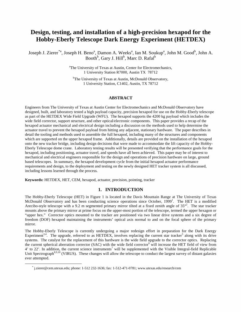
1. INTRODUCTION The Hobby-Eberly Telescope (HET) in Figure 1 is located in the Davis Mountain Range at The University of Texas McDonald Observatory and has been conducting science operations since October, 19991. The HET is a modified Arecibo-style telescope with a 9.2 m segmented primary mirror tilted at a fixed zenith angle of 35°2. The star tracker mounts above the primary mirror at prime focus on the upper-most portion of the telescope, termed the upper hexagon or “upper hex.” Corrector optics mounted to the tracker are positioned via two linear drive systems and a six degree of freedom (DOF) hexapod maintaining the instruments’ optical axis normal to and on the focal sphere of the primary mirror.
The Hobby-Eberly Telescope is currently undergoing a major redesign effort in preparation for the Dark Energy Experiment3,4. The upgrade, referred to as HETDEX, involves replacing the current star tracker5 along with its drive systems. The catalyst for the replacement of this hardware is the wide field upgrade to the corrector optics. Replacing the current spherical aberration corrector (SAC) with the wide field corrector6 will increase the HET field of view from 4’ to 22’. In addition, the current science instruments7 will be supplemented with the Visible Integral-field Replicable Unit Spectrograph8,9,10 (VIRUS). These changes will allow the telescope to conduct the largest survey of distant galaxies ever attempted.
* [email protected]; phone: 1-512 232-1636; fax: 1-512-471-0781; www.utexas.edu/research/cem
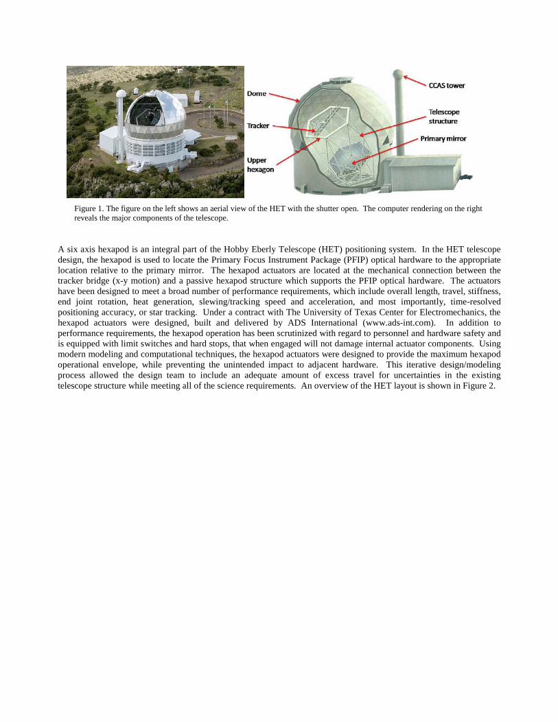
Figure 1. The figure on the left shows an aerial view of the HET with the shutter open. The computer rendering on the right reveals the major components of the telescope.
A six axis hexapod is an integral part of the Hobby Eberly Telescope (HET) positioning system. In the HET telescope design, the hexapod is used to locate the Primary Focus Instrument Package (PFIP) optical hardware to the appropriate location relative to the primary mirror. The hexapod actuators are located at the mechanical connection between the tracker bridge (x-y motion) and a passive hexapod structure which supports the PFIP optical hardware. The actuators have been designed to meet a broad number of performance requirements, which include overall length, travel, stiffness, end joint rotation, heat generation, slewing/tracking speed and acceleration, and most importantly, time-resolved positioning accuracy, or star tracking. Under a contract with The University of Texas Center for Electromechanics, the hexapod actuators were designed, built and delivered by ADS International (www.ads-int.com). In addition to performance requirements, the hexapod operation has been scrutinized with regard to personnel and hardware safety and is equipped with limit switches and hard stops, that when engaged will not damage internal actuator components. Using modern modeling and computational techniques, the hexapod actuators were designed to provide the maximum hexapod operational envelope, while preventing the unintended impact to adjacent hardware. This iterative design/modeling process allowed the design team to include an adequate amount of excess travel for uncertainties in the existing telescope structure while meeting all of the science requirements. An overview of the HET layout is shown in Figure 2.
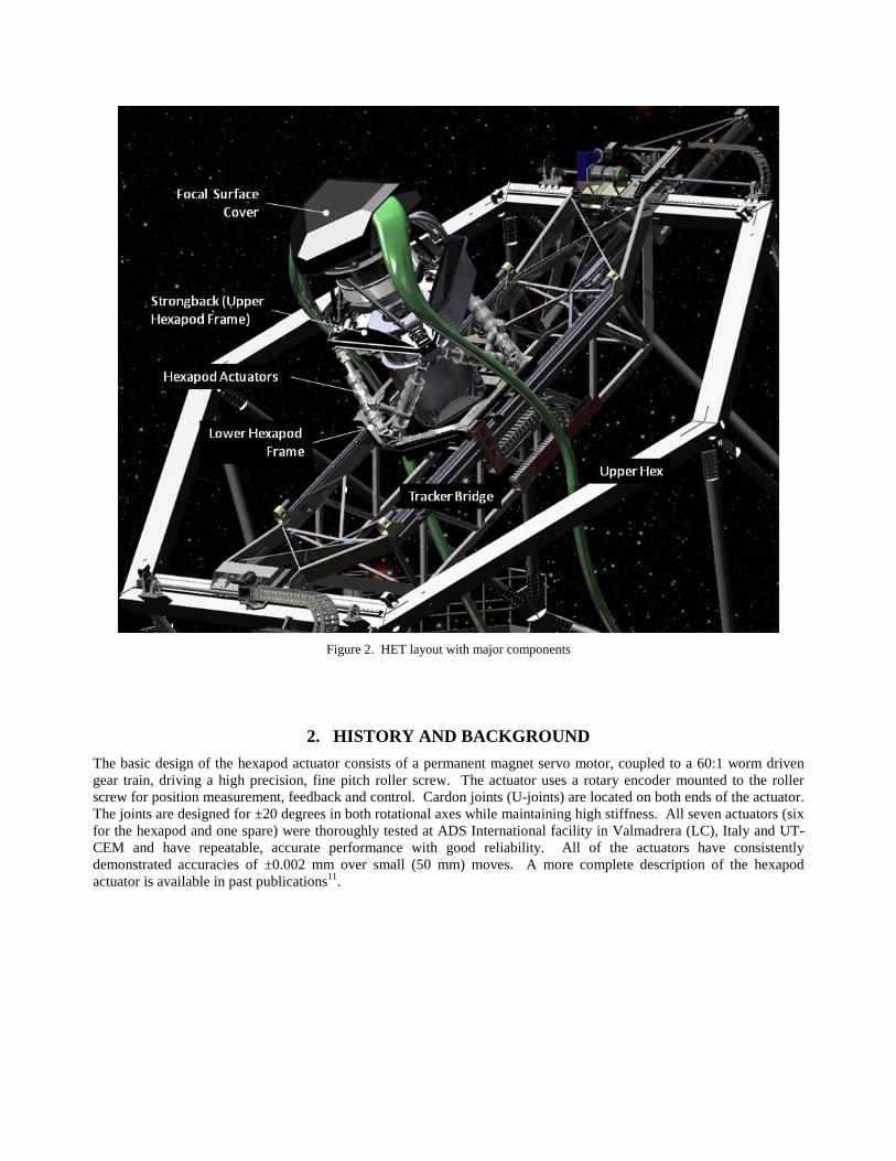
Figure 2. HET layout with major components
2. HISTORY AND BACKGROUND The basic design of the hexapod actuator consists of a permanent magnet servo motor, coupled to a 60:1 worm driven gear train, driving a high precision, fine pitch roller screw. The actuator uses a rotary encoder mounted to the roller screw for position measurement, feedback and control. Cardon joints (U-joints) are located on both ends of the actuator. The joints are designed for ±20 degrees in both rotational axes while maintaining high stiffness. All seven actuators (six for the hexapod and one spare) were thoroughly tested at ADS International facility in Valmadrera (LC), Italy and UT-CEM and have repeatable, accurate performance with good reliability. All of the actuators have consistently demonstrated accuracies of ±0.002 mm over small (50 mm) moves. A more complete description of the hexapod actuator is available in past publications11.
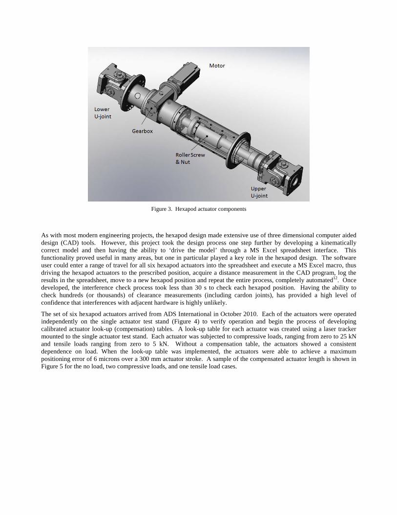
Figure 3. Hexapod actuator components
As with most modern engineering projects, the hexapod design made extensive use of three dimensional computer aided design (CAD) tools. However, this project took the design process one step further by developing a kinematically correct model and then having the ability to ‘drive the model’ through a MS Excel spreadsheet interface. This functionality proved useful in many areas, but one in particular played a key role in the hexapod design. The software user could enter a range of travel for all six hexapod actuators into the spreadsheet and execute a MS Excel macro, thus driving the hexapod actuators to the prescribed position, acquire a distance measurement in the CAD program, log the results in the spreadsheet, move to a new hexapod position and repeat the entire process, completely automated12. Once developed, the interference check process took less than 30 s to check each hexapod position. Having the ability to check hundreds (or thousands) of clearance measurements (including cardon joints), has provided a high level of confidence that interferences with adjacent hardware is highly unlikely.
The set of six hexapod actuators arrived from ADS International in October 2010. Each of the actuators were operated independently on the single actuator test stand (Figure 4) to verify operation and begin the process of developing calibrated actuator look-up (compensation) tables. A look-up table for each actuator was created using a laser tracker mounted to the single actuator test stand. Each actuator was subjected to compressive loads, ranging from zero to 25 kN and tensile loads ranging from zero to 5 kN. Without a compensation table, the actuators showed a consistent dependence on load. When the look-up table was implemented, the actuators were able to achieve a maximum positioning error of 6 microns over a 300 mm actuator stroke. A sample of the compensated actuator length is shown in Figure 5 for the no load, two compressive loads, and one tensile load cases.
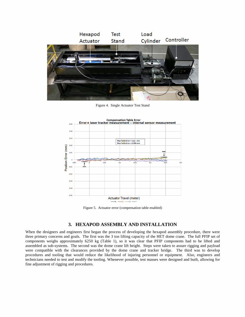
Figure 4. Single Actuator Test Stand
Figure 5. Actuator error (compensation table enabled)
3. HEXAPOD ASSEMBLY AND INSTALLATION When the designers and engineers first began the process of developing the hexapod assembly procedure, there were three primary concerns and goals. The first was the 3 ton lifting capacity of the HET dome crane. The full PFIP set of components weighs approximately 6250 kg (Table 1), so it was clear that PFIP components had to be lifted and assembled as sub-systems. The second was the dome crane lift height. Steps were taken to assure rigging and payload were compatible with the clearances provided by the dome crane and tracker bridge. The third was to develop procedures and tooling that would reduce the likelihood of injuring personnel or equipment. Also, engineers and technicians needed to test and modify the tooling. Whenever possible, test masses were designed and built, allowing for fine adjustment of rigging and procedures.
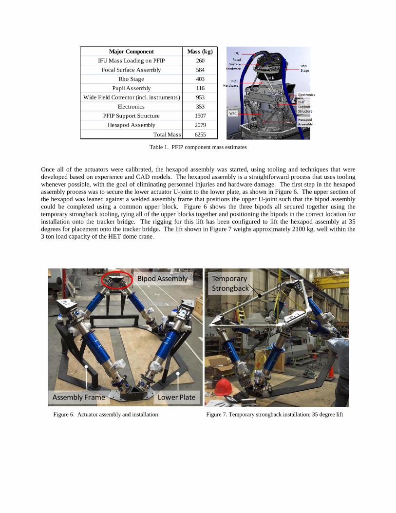
Table 1. PFIP component mass estimates
Once all of the actuators were calibrated, the hexapod assembly was started, using tooling and techniques that were developed based on experience and CAD models. The hexapod assembly is a straightforward process that uses tooling whenever possible, with the goal of eliminating personnel injuries and hardware damage. The first step in the hexapod assembly process was to secure the lower actuator U-joint to the lower plate, as shown in Figure 6. The upper section of the hexapod was leaned against a welded assembly frame that positions the upper U-joint such that the bipod assembly could be completed using a common upper block. Figure 6 shows the three bipods all secured together using the temporary strongback tooling, tying all of the upper blocks together and positioning the bipods in the correct location for installation onto the tracker bridge. The rigging for this lift has been configured to lift the hexapod assembly at 35 degrees for placement onto the tracker bridge. The lift shown in Figure 7 weighs approximately 2100 kg, well within the 3 ton load capacity of the HET dome crane.
Figure 6. Actuator assembly and installation Figure 7. Temporary strongback installation; 35 degree lift
Major Component Mass (kg)IFU Mass Loading on PFIP 260
Focal Surface Assembly 584Rho Stage 403
Pupil Assembly 116Wide Field Corrector (incl. instruments) 953
Electronics 353PFIP Support Structure 1507
Hexapod Assembly 2079Total Mass 6255
Lower PlateAssembly Frame
Bipod AssemblyTemporaryStrongback
Bipod Assembly
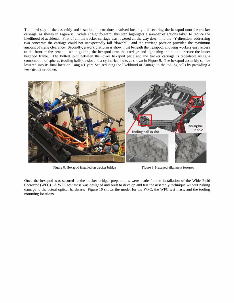
The third step in the assembly and installation procedure involved locating and securing the hexapod onto the tracker carriage, as shown in Figure 8. While straightforward, this step highlights a number of actions taken to reduce the likelihood of accidents. First of all, the tracker carriage was lowered all the way down into the –Y direction, addressing two concerns: the carriage could not unexpectedly fall ‘downhill’ and the carriage position provided the maximum amount of crane clearance. Secondly, a work platform is shown just beneath the hexapod, allowing workers easy access to the front of the hexapod while guiding the hexapod onto the carriage and tightening the bolts to secure the lower hexapod frame. The bolted joint between the lower hexapod plate and the tracker carriage is repeatable using a combination of spheres (tooling balls), a slot and a cylindrical hole, as shown in Figure 9. The hexapod assembly can be lowered into its final location using a Hydra Set, reducing the likelihood of damage to the tooling balls by providing a very gentle set down.
Figure 8. Hexapod installed on tracker bridge Figure 9. Hexapod alignment features
Once the hexapod was secured to the tracker bridge, preparations were made for the installation of the Wide Field Corrector (WFC). A WFC test mass was designed and built to develop and test the assembly technique without risking damage to the actual optical hardware. Figure 10 shows the model for the WFC, the WFC test mass, and the tooling mounting locations.
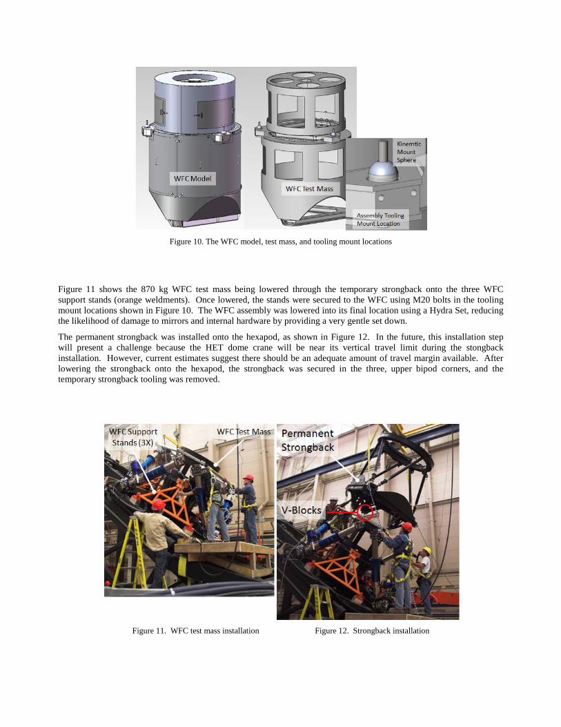
Figure 10. The WFC model, test mass, and tooling mount locations
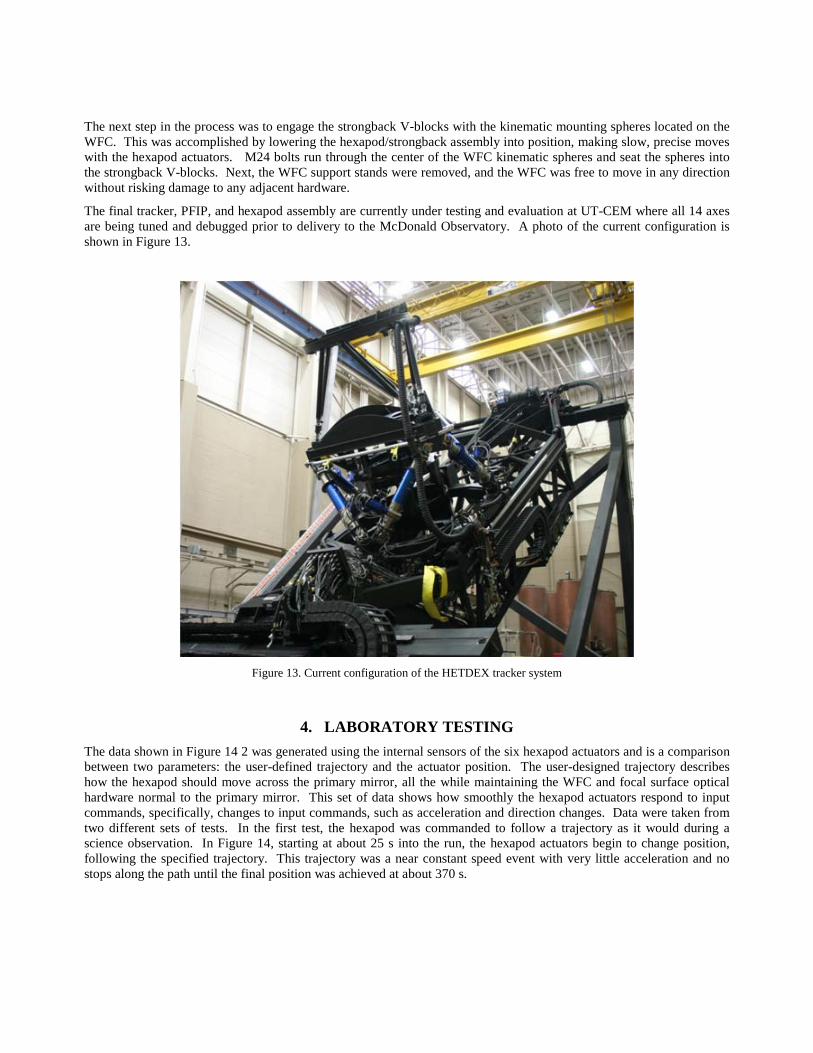
Figure 11 shows the 870 kg WFC test mass being lowered through the temporary strongback onto the three WFC support stands (orange weldments). Once lowered, the stands were secured to the WFC using M20 bolts in the tooling mount locations shown in Figure 10. The WFC assembly was lowered into its final location using a Hydra Set, reducing the likelihood of damage to mirrors and internal hardware by providing a very gentle set down.
The permanent strongback was installed onto the hexapod, as shown in Figure 12. In the future, this installation step will present a challenge because the HET dome crane will be near its vertical travel limit during the stongback installation. However, current estimates suggest there should be an adequate amount of travel margin available. After lowering the strongback onto the hexapod, the strongback was secured in the three, upper bipod corners, and the temporary strongback tooling was removed.
Figure 11. WFC test mass installation Figure 12. Strongback installation
The next step in the process was to engage the strongback V-blocks with the kinematic mounting spheres located on the WFC. This was accomplished by lowering the hexapod/strongback assembly into position, making slow, precise moves with the hexapod actuators. M24 bolts run through the center of the WFC kinematic spheres and seat the spheres into the strongback V-blocks. Next, the WFC support stands were removed, and the WFC was free to move in any direction without risking damage to any adjacent hardware.
The final tracker, PFIP, and hexapod assembly are currently under testing and evaluation at UT-CEM where all 14 axes are being tuned and debugged prior to delivery to the McDonald Observatory. A photo of the current configuration is shown in Figure 13.
Figure 13. Current configuration of the HETDEX tracker system
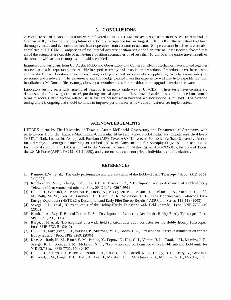
4. LABORATORY TESTING The data shown in Figure 14 2 was generated using the internal sensors of the six hexapod actuators and is a comparison between two parameters: the user-defined trajectory and the actuator position. The user-designed trajectory describes how the hexapod should move across the primary mirror, all the while maintaining the WFC and focal surface optical hardware normal to the primary mirror. This set of data shows how smoothly the hexapod actuators respond to input commands, specifically, changes to input commands, such as acceleration and direction changes. Data were taken from two different sets of tests. In the first test, the hexapod was commanded to follow a trajectory as it would during a science observation. In Figure 14, starting at about 25 s into the run, the hexapod actuators begin to change position, following the specified trajectory. This trajectory was a near constant speed event with very little acceleration and no stops along the path until the final position was achieved at about 370 s.
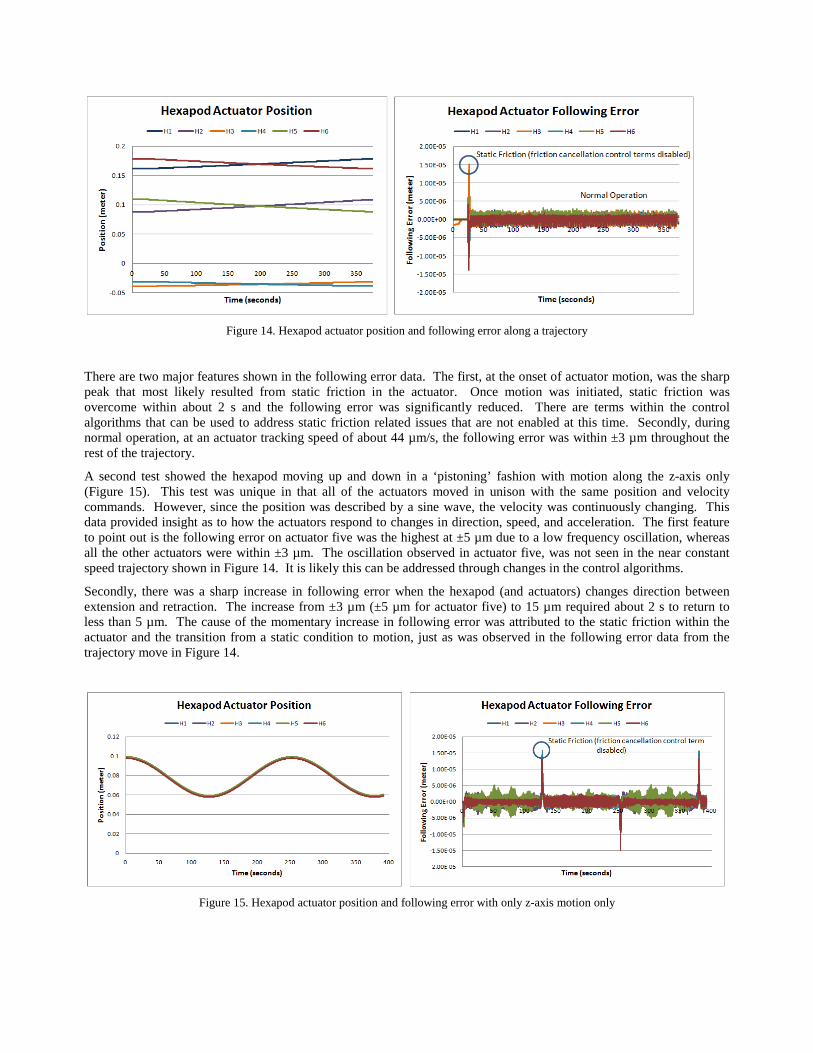
Figure 14. Hexapod actuator position and following error along a trajectory
There are two major features shown in the following error data. The first, at the onset of actuator motion, was the sharp peak that most likely resulted from static friction in the actuator. Once motion was initiated, static friction was overcome within about 2 s and the following error was significantly reduced. There are terms within the control algorithms that can be used to address static friction related issues that are not enabled at this time. Secondly, during normal operation, at an actuator tracking speed of about 44 µm/s, the following error was within ±3 µm throughout the rest of the trajectory.
A second test showed the hexapod moving up and down in a ‘pistoning’ fashion with motion along the z-axis only (Figure 15). This test was unique in that all of the actuators moved in unison with the same position and velocity commands. However, since the position was described by a sine wave, the velocity was continuously changing. This data provided insight as to how the actuators respond to changes in direction, speed, and acceleration. The first feature to point out is the following error on actuator five was the highest at ±5 µm due to a low frequency oscillation, whereas all the other actuators were within ±3 µm. The oscillation observed in actuator five, was not seen in the near constant speed trajectory shown in Figure 14. It is likely this can be addressed through changes in the control algorithms.
Secondly, there was a sharp increase in following error when the hexapod (and actuators) changes direction between extension and retraction. The increase from ±3 µm (±5 µm for actuator five) to 15 µm required about 2 s to return to less than 5 µm. The cause of the momentary increase in following error was attributed to the static friction within the actuator and the transition from a static condition to motion, just as was observed in the following error data from the trajectory move in Figure 14.
Figure 15. Hexapod actuator position and following error with only z-axis motion only
5. CONCLUSIONS A complete set of hexapod actuators were delivered to the UT-CEM tracker design team from ADS International in October 2010, following the completion of a factory acceptance test in August 2010. All of the actuators had been thoroughly tested and demonstrated consistent operation from actuator to actuator. Single actuator bench tests were also completed at UT-CEM. Comparison of the internal actuator position sensor and an external laser tracker, showed that all of the actuators are capable of achieving a position accuracy error of less than 10 µm over the entire travel length of the actuator with actuator compensation tables enabled.
Engineers and designers from UT Austin McDonald Observatory and Center for Electromechanics have worked together to develop a safe, repeatable, and reliable hexapod assembly and installation procedure. Procedures have been tested and verified in a laboratory environment using tooling and test masses (where applicable) to help insure safety to personnel and hardware. The experience and knowledge gleaned from this experience will also help expedite the final installation at McDonald Observatory, allowing a smoother and safer transition to the upgraded tracker hardware.
Laboratory testing on a fully assembled hexapod is currently underway at UT-CEM. These tests have consistently demonstrated a following error of ±3 µm during normal operation. Tests have also demonstrated the need for control terms to address static friction related issues that are present when hexapod actuator motion is initiated. The hexapod tuning effort is ongoing and should continue to improve performance as new control features are implemented.
ACKNOWLEDGEMENTS HETDEX is run by The University of Texas at Austin McDonald Observatory and Department of Astronomy with participation from the Ludwig-Maximilians-Universität München, Max-Planck-Institut für Extraterrestriche-Physik (MPE), Leibniz-Institut für Astrophysik Potsdam (AIP), Texas A&M University, Pennsylvania State University, Institut für Astrophysik Göttingen, University of Oxford and Max-Planck-Institut für Astrophysik (MPA). In addition to Institutional support, HETDEX is funded by the National Science Foundation (grant AST-0926815), the State of Texas, the US Air Force (AFRL FA9451-04-2-0355), and generous support from private individuals and foundations.
REFERENCES
[1] Ramsey, L.W., et al., “The early performance and present status of the Hobby-Eberly Telescope,” Proc. SPIE 3352, 34 (1998)
[2] Krabbendam, V.L., Sebring, T.A., Ray, F.B. & Fowler, J.R., “Development and performance of Hobby-Eberly Telescope 11-m segmented mirror,” Proc. SPIE 3352, 436 (1998)
[3] Hill, G. J., Gebhardt, K., Komatsu, E., Drory, N., MacQueen, P. J., Adams, J. J., Blanc, G. A., Koehler, R., Rafal, M., Roth, M. M., Kelz, A., Gronwall, C., Ciardullo, R., Schneider, D. P., "The Hobby-Eberly Telescope Dark Energy Experiment (HETDEX): Description and Early Pilot Survey Results," ASP Conf. Series, 115-118 (2008)
[4] Savage, R.D., et al., "Current status of the Hobby-Eberly Telescope wide-field upgrade," Proc. SPIE 7733-149 (2010)
[5] Booth, J. A., Ray, F. B., and Porter, D. S., "Development of a star tracker for the Hobby Eberly Telescope," Proc. SPIE 3351, 20 (1998)
[6] Burge, J. H. et al, "Development of a wide-field spherical aberration corrector for the Hobby-Eberly Telescope," Proc. SPIE 7733-51 (2010)
[7] Hill, G. J., MacQueen, P. J., Palunas, P., Shetrone, M. D., Booth, J. A., “Present and Future Instrumentation for the Hobby-Eberly,” Proc. SPIE 6269, (2006)
[8] Kelz, A., Roth, M. M., Bauer, S. M., Padilla, Y., Popow, E., Hill, G. J., Vattiat, B. L., Good, J. M., Murphy, J. D., Savage, R. D., Soukup, I. M., Mollison, N. T., “Production and performance of replicable integral field units for VIRUS,” Proc. SPIE 7735, 178 (2010)
[9] Hill, G. J., Adams, J. J., Blanc, G., Booth, J. A., Chonis, T. S., Cornell, M. E., DePoy, D. L., Drory, N., Gebhardt, K., Good, J. M., Grupp, F. U., Kelz, A., Lee, H., Marshall, J. L., MacQueen, P. J., Mollison, N. T., Murphy, J. D.,
Rafal, M. D., “VIRUS: a massively replicated 33k fiber integral field spectrograph for the upgraded Hobby-Eberly Telescope,” Proc. SPIE 7735, 21 (2010)
[10] Lee, H., Hill, G. J., Marshall, J. L., DePoy, D. L., Vattiat, B. L., “VIRUS optical tolerance and production,” Proc. SPIE 7735, 140 (2010)
[11] Zierer, J. J., et al., ”The development of high-precision hexapod actuators for the Hobby-Eberly Telescope Dark Energy Experiment (HETDEX),” Proc. SPIE, 7733-49 (2010).
[12] Wedeking, G.A., et al., “Kinematic optimization of upgrade to the Hobby-Eberly Telescope through novel use of commercially available three-dimensional CAD package,” Proc. SPIE, 7733-148 (2010)
[13] Lazzarini, P., Fumi, P., Gallieni, D., "Hobby-Eberly Telescope Hexapod Actuator Prototype Actuator Test Procedure and Report," Issue E, (May 2010)