Embed Size (px)
Citation preview

ND DEPT OF TRANSPORTATION SURVEYS & PHOTOGRAMMETRY DATE: SEPTEMBER 18, 2006 REVISED: March 10, 2008
3/12/2008
TRAINING MANUAL
FOR
DESIGN TO CONSTRUCTION SURVEY AUTOMATION
NOTE: This manual provides a written account of how certain activities are performed and is designed to guide and assist staff members in performing their functions. When appropriate, there may be deviations from these written procedures due to changes in personnel, policies, interpretation, law, experimentation with different systems, or simply evolution of the process itself. This manual may be changed at any time. Staff members are encouraged to review this manual periodically and suggest changes in the manual to keep the manual current and to minimize differences between the manual and actual practices.

ND DEPT OF TRANSPORTATION SURVEYS & PHOTOGRAMMETRY TRAINING SUBJECT: DESIGN TO CONSTRUCTION SURVEY AUTOMATION
3/12/2008
INDEX Geopak GPK data to Trimble 1 - 18 Converting State Plane Grid Coordinates to State Plane Ground in TGO 19 - 28 Control and Roadlink Data to Trimble DC file for upload 29 - 36 Creating a DTX file with Geopak 37 - 40 Importing a DTX file into TGO DTMLink 41 - 46
CONTENTS PAGE

ND DEPT OF TRANSPORTATION SURVEYS & PHOTOGRAMMETRY TRAINING SUBJECT: DESIGN TO CONSTRUCTION SURVEY AUTOMATION
3/12/2008 1
GeoPak GPK Data to Trimble
Step1: Get the cross-section file and the geopak job file from the design folder in the r:\ drive for the project.
Find out from the designer which files were used for cross-sections. (Usually Microstation file named “xsec.dgn” and geopak file named “job001.gpk”)
Put these two files in a new folder.

ND DEPT OF TRANSPORTATION SURVEYS & PHOTOGRAMMETRY TRAINING SUBJECT: DESIGN TO CONSTRUCTION SURVEY AUTOMATION
2 3/12/2008
NOTE: Step 2 can be skipped if the gpk files and dgn files are located in the same folder. GeoPak will then default to the working folder. If files are located in different folders, step 2 must be used each time a project is opened.
Step 2: Open “xsec.dgn”. Open : Applications-Geopak Road-User Preferences

ND DEPT OF TRANSPORTATION SURVEYS & PHOTOGRAMMETRY TRAINING SUBJECT: DESIGN TO CONSTRUCTION SURVEY AUTOMATION
3/12/2008 3
Step 2 Cont.: Select your working directory: (The folder you made in step 1) Hit OK

ND DEPT OF TRANSPORTATION SURVEYS & PHOTOGRAMMETRY TRAINING SUBJECT: DESIGN TO CONSTRUCTION SURVEY AUTOMATION
4 3/12/2008
Click on COGO Preferences and Change all three directories to your new folder.

ND DEPT OF TRANSPORTATION SURVEYS & PHOTOGRAMMETRY TRAINING SUBJECT: DESIGN TO CONSTRUCTION SURVEY AUTOMATION
3/12/2008 5
Step 3: In Geopak, open Applications-Geopak Road-Geometry-Coordinate Geometry. NOTE: Refer to Chapter 4.1 of the NDDOT CADD Standards for further information.

ND DEPT OF TRANSPORTATION SURVEYS & PHOTOGRAMMETRY TRAINING SUBJECT: DESIGN TO CONSTRUCTION SURVEY AUTOMATION
6 3/12/2008
Step 3 Cont: Make up a name for the project. Select the .gpk file where the chains and profiles are stored (Job001.gpk) Type nd for operator code. You can leave subject blank. Click OK.

ND DEPT OF TRANSPORTATION SURVEYS & PHOTOGRAMMETRY TRAINING SUBJECT: DESIGN TO CONSTRUCTION SURVEY AUTOMATION
3/12/2008 7
Step 4: In the Coordinate Geometry Dialog Box, press: File-Export-Alignment and Profiles.

ND DEPT OF TRANSPORTATION SURVEYS & PHOTOGRAMMETRY TRAINING SUBJECT: DESIGN TO CONSTRUCTION SURVEY AUTOMATION
8 3/12/2008
Step 5: For “Export Format” select TRIMBLE DC, Version 7.5, Intl Foot. Click on Chain and select the chain, Click on Profile and select the profile. (There may be several. You will have to check with the designer to know which one to use for the final design and for each alignment)
Make up a name for your new .dc file in the Output File. (Make sure to put the .dc file extension behind the name)
.dc

ND DEPT OF TRANSPORTATION SURVEYS & PHOTOGRAMMETRY TRAINING SUBJECT: DESIGN TO CONSTRUCTION SURVEY AUTOMATION
3/12/2008 9
Step 5 Cont.: Click Apply.
Now you have created a “.dc” file in your working directory. Now you can append CrossSection Template information to this file with the following steps. Hit OK.
ND DEPT OF TRANSPORTATION SURVEYS & PHOTOGRAMMETRY TRAINING SUBJECT: DESIGN TO CONSTRUCTION SURVEY AUTOMATION
10 3/12/2008
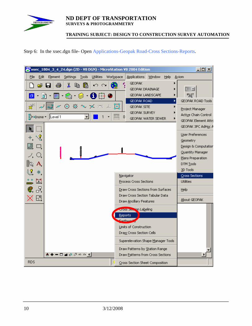
Step 6: In the xsec.dgn file- Open Applications-Geopak Road-Cross Sections-Reports.

ND DEPT OF TRANSPORTATION SURVEYS & PHOTOGRAMMETRY TRAINING SUBJECT: DESIGN TO CONSTRUCTION SURVEY AUTOMATION
3/12/2008 11
Select Multi-Line.
ND DEPT OF TRANSPORTATION SURVEYS & PHOTOGRAMMETRY TRAINING SUBJECT: DESIGN TO CONSTRUCTION SURVEY AUTOMATION
12 3/12/2008
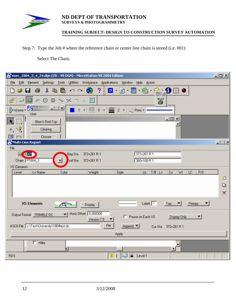
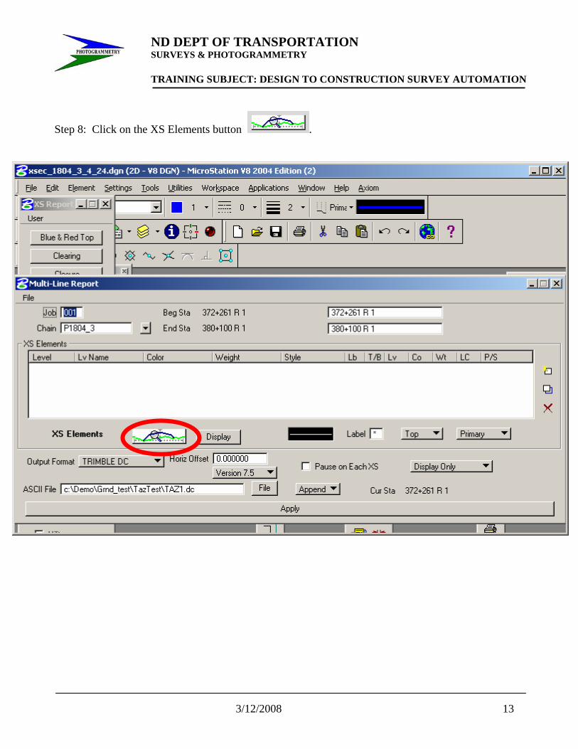
Step 7: Type the Job # where the reference chain or center line chain is stored (i.e. 001)
Select The Chain.
ND DEPT OF TRANSPORTATION SURVEYS & PHOTOGRAMMETRY TRAINING SUBJECT: DESIGN TO CONSTRUCTION SURVEY AUTOMATION
3/12/2008 13
Step 8: Click on the XS Elements button .
ND DEPT OF TRANSPORTATION SURVEYS & PHOTOGRAMMETRY TRAINING SUBJECT: DESIGN TO CONSTRUCTION SURVEY AUTOMATION
14 3/12/2008
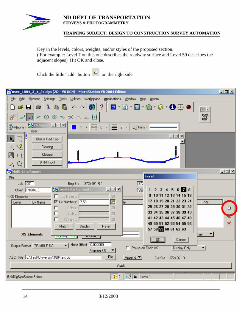
Key in the levels, colors, weights, and/or styles of the proposed section. ( For example: Level 7 on this one describes the roadway surface and Level 59 describes the adjacent slopes) Hit OK and close.
Click the little “add” button on the right side.
ND DEPT OF TRANSPORTATION SURVEYS & PHOTOGRAMMETRY TRAINING SUBJECT: DESIGN TO CONSTRUCTION SURVEY AUTOMATION
3/12/2008 15
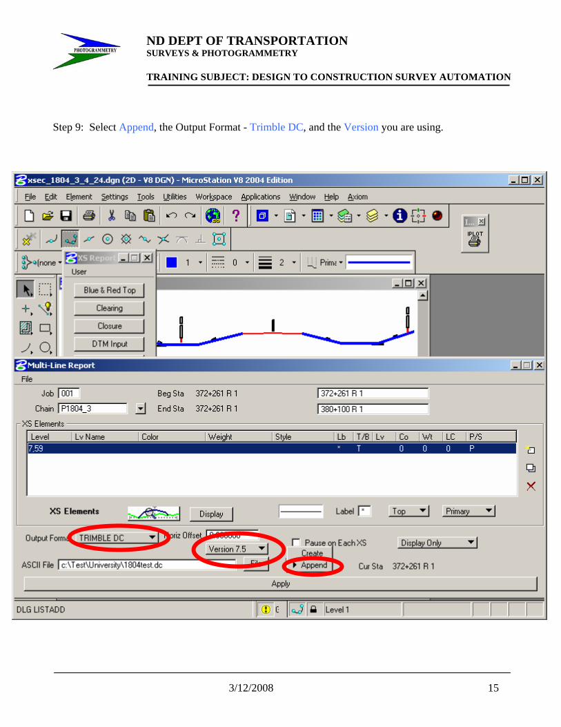
Step 9: Select Append, the Output Format - Trimble DC, and the Version you are using.

ND DEPT OF TRANSPORTATION SURVEYS & PHOTOGRAMMETRY TRAINING SUBJECT: DESIGN TO CONSTRUCTION SURVEY AUTOMATION
16 3/12/2008
Click on the File button next to Append and Select the file you created in step 5 located in your working directory. Be sure that the .dc file extension is typed into this field also.

ND DEPT OF TRANSPORTATION SURVEYS & PHOTOGRAMMETRY TRAINING SUBJECT: DESIGN TO CONSTRUCTION SURVEY AUTOMATION
3/12/2008 17
Step 10: Click Apply
GeoPak will now extract the necessary cross section data and exports this to your selected .dc file created in Step 5.

ND DEPT OF TRANSPORTATION SURVEYS & PHOTOGRAMMETRY TRAINING SUBJECT: DESIGN TO CONSTRUCTION SURVEY AUTOMATION
18 3/12/2008
Step 11: Be sure to locate your Trimble .dc file before closing.

ND DEPT OF TRANSPORTATION SURVEYS & PHOTOGRAMMETRY TRAINING SUBJECT: DESIGN TO CONSTRUCTION SURVEY AUTOMATION
3/12/2008 19
Converting State Plane Grid Coordinates
to State Plane Ground in TGO
Step 1: Open TGO and Select New Project.

ND DEPT OF TRANSPORTATION SURVEYS & PHOTOGRAMMETRY TRAINING SUBJECT: DESIGN TO CONSTRUCTION SURVEY AUTOMATION
20 3/12/2008
Step 2: Type in Project Name. Select the Folder button and select the folder that you want to store the project in.
Select Nzone04 or Szone04 ( This will be determined by where the project is located). To determine which State Plane Zone you are in refer to Chaper 19 in the Surveys and Photogrammetry Manual Page 19-23. Hit OK
ND DEPT OF TRANSPORTATION SURVEYS & PHOTOGRAMMETRY TRAINING SUBJECT: DESIGN TO CONSTRUCTION SURVEY AUTOMATION
3/12/2008 21
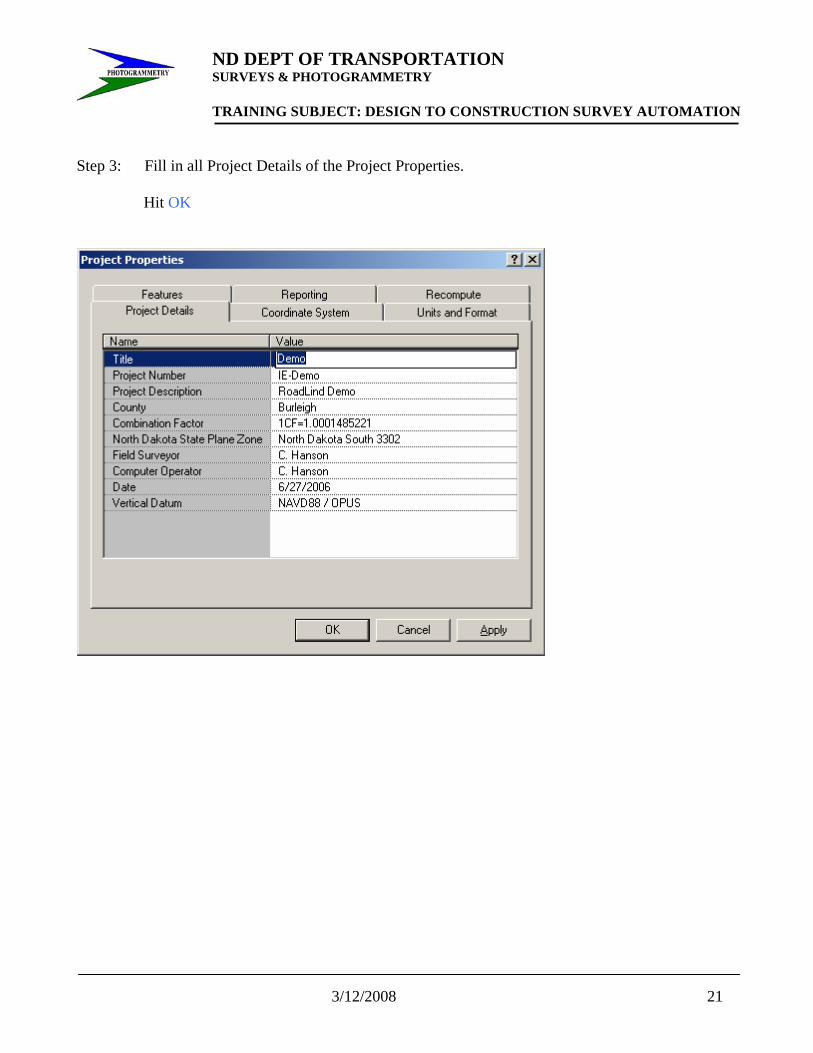
Step 3: Fill in all Project Details of the Project Properties.
Hit OK

ND DEPT OF TRANSPORTATION SURVEYS & PHOTOGRAMMETRY TRAINING SUBJECT: DESIGN TO CONSTRUCTION SURVEY AUTOMATION
22 3/12/2008
Step 4: Key in or import .csv Grid coordinates coordinates into TGO.
OR

ND DEPT OF TRANSPORTATION SURVEYS & PHOTOGRAMMETRY TRAINING SUBJECT: DESIGN TO CONSTRUCTION SURVEY AUTOMATION
3/12/2008 23
Step 5: Go to File then select Project Properties and the following table will appear: Select the Coordinate System Tab. Go to Local Site Settings and hit Change.

ND DEPT OF TRANSPORTATION SURVEYS & PHOTOGRAMMETRY TRAINING SUBJECT: DESIGN TO CONSTRUCTION SURVEY AUTOMATION
24 3/12/2008
Step 6: In Project location put “0” (zero) in for the Northing, Easting, and Elevation. Check Mark “Use Ground Coordinates”. Key in the 1/CF county scale factor. Hit OK.

ND DEPT OF TRANSPORTATION SURVEYS & PHOTOGRAMMETRY TRAINING SUBJECT: DESIGN TO CONSTRUCTION SURVEY AUTOMATION
3/12/2008 25
NOTE: You will notice the System has changed to US State Plane 1983 (at Ground). Hit OK.

ND DEPT OF TRANSPORTATION SURVEYS & PHOTOGRAMMETRY TRAINING SUBJECT: DESIGN TO CONSTRUCTION SURVEY AUTOMATION
26 3/12/2008
Exporting State Plane Ground Job to Data Collector
Step 1: Go to the Export tab on the left hand side of the screen.
Select Survey Device.

ND DEPT OF TRANSPORTATION SURVEYS & PHOTOGRAMMETRY TRAINING SUBJECT: DESIGN TO CONSTRUCTION SURVEY AUTOMATION
3/12/2008 27
Step 2: Select Survey Controller on ActiveSync for the controller you are using. Hit open. The Job that is currently open will be in the File Name Box. Hit Save.

ND DEPT OF TRANSPORTATION SURVEYS & PHOTOGRAMMETRY TRAINING SUBJECT: DESIGN TO CONSTRUCTION SURVEY AUTOMATION
28 3/12/2008
Step 2: The Job that is currently open will be in the File Name Box. Hit Save.

ND DEPT OF TRANSPORTATION SURVEYS & PHOTOGRAMMETRY TRAINING SUBJECT: DESIGN TO CONSTRUCTION SURVEY AUTOMATION
3/12/2008 29
Control and RoadLink Data To Trimble DC File for Upload
Step 1: Open TGO with project containing ground control points and other necessary data.

ND DEPT OF TRANSPORTATION SURVEYS & PHOTOGRAMMETRY TRAINING SUBJECT: DESIGN TO CONSTRUCTION SURVEY AUTOMATION
30 3/12/2008
Step 2: Go to the Export tab on the left hand side of the screen or
Select Survey Controller DC File.

ND DEPT OF TRANSPORTATION SURVEYS & PHOTOGRAMMETRY TRAINING SUBJECT: DESIGN TO CONSTRUCTION SURVEY AUTOMATION
3/12/2008 31
Step 3: Select the folder that you want to save the DC file to (TGO defaults to the Export folder under
the current project folder).
The Job that is currently open will be in the File Name Box.
Hit Save.
This will create the base Trimble DC file with the needed ground control data.

ND DEPT OF TRANSPORTATION SURVEYS & PHOTOGRAMMETRY TRAINING SUBJECT: DESIGN TO CONSTRUCTION SURVEY AUTOMATION
32 3/12/2008
Step 4: Select Plan View option by using the pull down menu VIEW – PLAN. or
Open RoadLink by going to pull down menu TOOLS - ROADLINK – START.

ND DEPT OF TRANSPORTATION SURVEYS & PHOTOGRAMMETRY TRAINING SUBJECT: DESIGN TO CONSTRUCTION SURVEY AUTOMATION
3/12/2008 33
Step 5: You now need to import the road file created by Geopak by selecting Import .
Select the Road definition from Trimble Survey Controller file. Hit OK after selecting your RoadLink .dc file road definition you want to import.

ND DEPT OF TRANSPORTATION SURVEYS & PHOTOGRAMMETRY TRAINING SUBJECT: DESIGN TO CONSTRUCTION SURVEY AUTOMATION
34 3/12/2008
Step 6: Open the Road that you created in the “GeoPak GPK Data to Trimble” procedures by selecting
from the FILE pull down menu OPEN ROAD.
Your Road should appear as follows:
ND DEPT OF TRANSPORTATION SURVEYS & PHOTOGRAMMETRY TRAINING SUBJECT: DESIGN TO CONSTRUCTION SURVEY AUTOMATION
3/12/2008 35
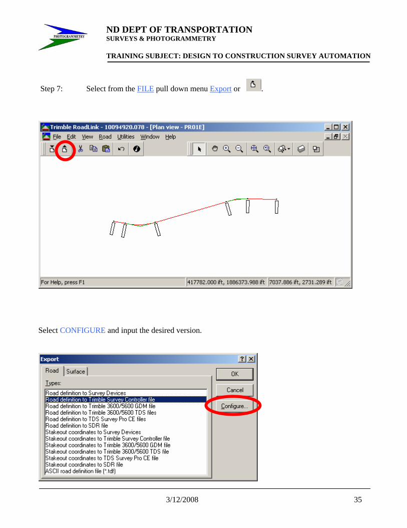
Step 7: Select from the FILE pull down menu Export or .
Select CONFIGURE and input the desired version.

ND DEPT OF TRANSPORTATION SURVEYS & PHOTOGRAMMETRY TRAINING SUBJECT: DESIGN TO CONSTRUCTION SURVEY AUTOMATION
36 3/12/2008
You then need to check the APPEND TO FILE box and link the DC file from step 3 containing your ground coordinate control. Hit OK. This will add the Road data to the original DC file.
NOTE: For projects with multiple alignments steps 5, 6, and 7 will need to be done for each Road file using the Append File detail.

ND DEPT OF TRANSPORTATION SURVEYS & PHOTOGRAMMETRY TRAINING SUBJECT: DESIGN TO CONSTRUCTION SURVEY AUTOMATION
3/12/2008 37
Creating a DTX file with Geopak
The first step is to have an already created TIN file. To begin we will need to create a Lattice file using the previous TIN file. From the Applications menu select GEOPAK ROAD-DTM Tools.
The following button bar will appear:

ND DEPT OF TRANSPORTATION SURVEYS & PHOTOGRAMMETRY TRAINING SUBJECT: DESIGN TO CONSTRUCTION SURVEY AUTOMATION
38 3/12/2008
Select the button to access the DTM Menu as shown below.
Select Build-Lattice.
Navigate to the desired TIN file and enter in the location and name of the LAT file you want to create. Then select Process.

ND DEPT OF TRANSPORTATION SURVEYS & PHOTOGRAMMETRY TRAINING SUBJECT: DESIGN TO CONSTRUCTION SURVEY AUTOMATION
3/12/2008 39
The next step will be to export a DTX file using the LAT file you just created. Go to the Survey menu and select DTM-DTM Export.

ND DEPT OF TRANSPORTATION SURVEYS & PHOTOGRAMMETRY TRAINING SUBJECT: DESIGN TO CONSTRUCTION SURVEY AUTOMATION
40 3/12/2008
For the Export select Lattice LAT to Trimble DTX. Navigate to and select the LAT file we created in the previous steps. Then navigate to the location you want the new DTX to be located and give a name that is appropriate. Select Process after the above steps have been completed.
Make sure the files exist where you want them.

ND DEPT OF TRANSPORTATION SURVEYS & PHOTOGRAMMETRY TRAINING SUBJECT: DESIGN TO CONSTRUCTION SURVEY AUTOMATION
3/12/2008 41
Importing a DTX file into TGO DTMLink First find the location of the DTX file.
Open the TGO project you will be working on.

ND DEPT OF TRANSPORTATION SURVEYS & PHOTOGRAMMETRY TRAINING SUBJECT: DESIGN TO CONSTRUCTION SURVEY AUTOMATION
42 3/12/2008
Select the plan view button, . Or use the View pull down menu and select Plan. From the Tools menu select DTMLink-Start.
ND DEPT OF TRANSPORTATION SURVEYS & PHOTOGRAMMETRY TRAINING SUBJECT: DESIGN TO CONSTRUCTION SURVEY AUTOMATION
3/12/2008 43
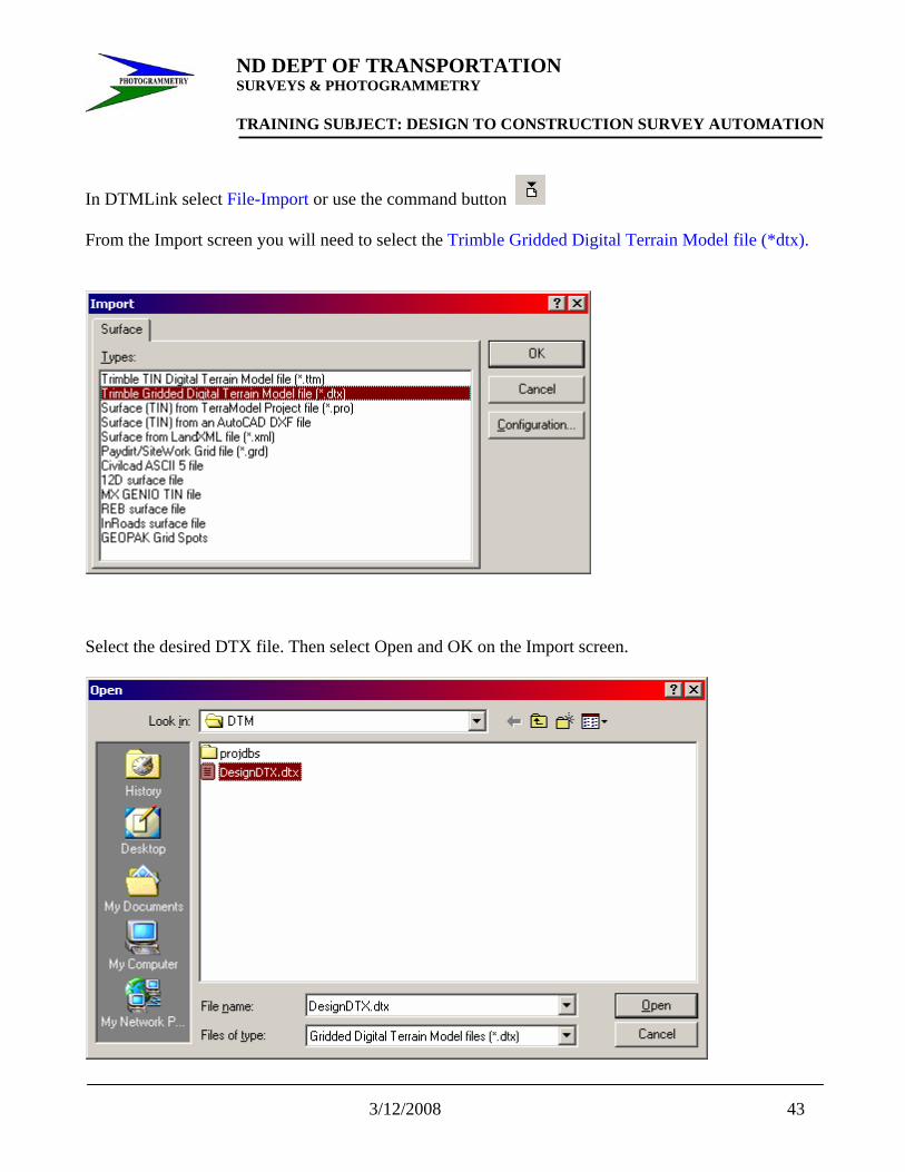
In DTMLink select File-Import or use the command button From the Import screen you will need to select the Trimble Gridded Digital Terrain Model file (*dtx).
Select the desired DTX file. Then select Open and OK on the Import screen.

ND DEPT OF TRANSPORTATION SURVEYS & PHOTOGRAMMETRY TRAINING SUBJECT: DESIGN TO CONSTRUCTION SURVEY AUTOMATION
44 3/12/2008
Now you should be able to review and check your DTM in DTMLink.

ND DEPT OF TRANSPORTATION SURVEYS & PHOTOGRAMMETRY TRAINING SUBJECT: DESIGN TO CONSTRUCTION SURVEY AUTOMATION
3/12/2008 45
This DTM can now be Exported using File-Export or the Export command button . You can now export to a Survey Controller or to a Trimble Survey Controller file (*.ttm)
A TIN Extents window will appear.

ND DEPT OF TRANSPORTATION SURVEYS & PHOTOGRAMMETRY TRAINING SUBJECT: DESIGN TO CONSTRUCTION SURVEY AUTOMATION
46 3/12/2008
Check to make sure it encompasses your whole DTM.
You may now view the DTM in V12.20