Embed Size (px)
Citation preview
Design Tradeoffs in Joint Powerline and WirelessTransmission for Smart Grid Communications
Ghadi Sebaali and Brian L. EvansEmbedded Signal Processing Laboratory
Wireless Networking and Communications GroupThe University of Texas at Austin
[email protected], [email protected]
Abstract—Providing reliable smart grid communication fromcustomers to the local utility faces significant challenges due tonoise, interference, frequency selectivity, path loss and fading.For transmission over narrowband powerline channels (3-500kHz) and unlicensed wireless channels (902-928 MHz), thispaper reviews previous approaches for (a) channel modeling andestimation and (b) noise/interference modeling and mitigation.Based on these approaches, the paper reviews methods forjoint transmission over the powerline and wireless channels toimprove reliability further. The key contribution of this paperis to explore design tradeoffs in communication performance vs.implementation complexity for joint transmission.
I. INTRODUCTION
According to the US Energy Information Administration,worldwide energy consumption from 2010 to 2040 is expectedto increase by 56% [1]. It is challenging to meet this increasewith the existing grid which has an aging infrastructure. Inthe US, the age of transmission lines is about 55 years [2].In response to the current grid limitations, the traditional gridis transformed into a smart grid which relies on technologiessuch as wireless and powerline communications (PLC).
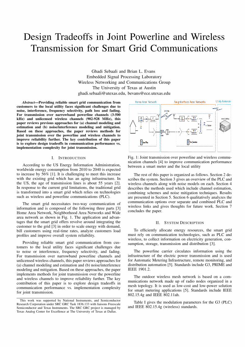
The smart grid necessitates two-way communication ofinformation and is composed of the following three parts [3]Home Area Network, Neighborhood Area Networks and Widearea network as shown in Fig. 1. The application and advan-tages that the smart grid offers revolve around integrating thecustomer to the grid [3] in order to scale energy with demand,bill customers using real-time rates, analyze customers loadprofiles and improve overall system reliability.
Providing reliable smart grid communication from cus-tomers to the local utility faces significant challenges dueto noise or interference, frequency selectivity, and fading.For transmission over narrowband powerline channels andunlicensed wireless channels, this paper reviews approaches for(a) channel modeling and estimation and (b) noise/interferencemodeling and mitigation. Based on these approaches, the paperimplements methods for joint transmission over the powerlineand wireless channels to improve reliability further. The keycontribution of this paper is to explore design tradeoffs incommunication performance vs. implementation complexityfor joint transmission.
This work was supported by National Instruments, and SemiconductorResearch Corporation under SRC GRC Task 1836.133 with liaisons FreescaleSemiconductor and Texas Instruments. The SRC GRC project is managed byTexas Analog Center for Excellence at The University of Texas at Dallas.
Fig. 1: Joint transmission over powerline and wireless commu-nication channels [4] to improve communication performancebetween a smart meter and the local utility
The rest of this paper is organized as follows. Section 2 de-scribes the system. Section 3 gives an overview of the PLC andwireless channels along with noise models on each. Section 4describes the methods used which include channel estimation,combining schemes and noise mitigation techniques. Resultsare presented in Section 5. Section 6 qualitatively analyzes thecommunication options over separate and combined PLC andwireless links and gives thoughts for future work. Section 7concludes the paper.
II. SYSTEM DESCRIPTION
To efficiently allocate energy resources, the smart gridmust rely on communication technologies, such as PLC andwireless, to collect information on electricity generation, con-sumption, storage, transmission and distribution [3].
The powerline carrier circulates information using theinfrastructure of the electric power transmission and is usedfor Automatic Metering Infrastructure, remote monitoring, anddistribution automation [5]. Standards include G3, PRIME andIEEE 1901.2.
The outdoor wireless mesh network is based on a com-munications network made up of radio nodes organized in amesh topology. It is used as low-cost and low-power solutionfor smart metering applications [5]. Standards include IEEE802.15.4g and IEEE 802.11ah.
Table I gives the modulation parameters for the G3 (PLC)and IEEE 802.15.4g (wireless) standards.
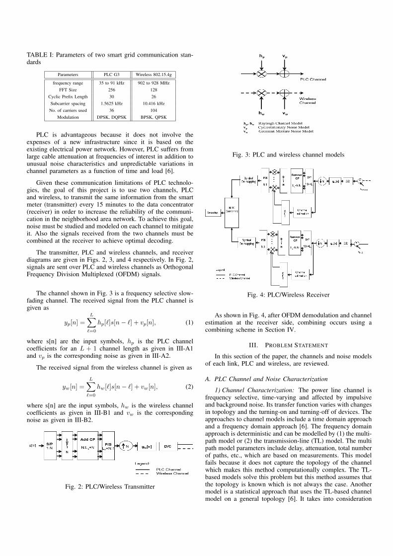
TABLE I: Parameters of two smart grid communication stan-dards
Parameters PLC G3 Wireless 802.15.4g
frequency range 35 to 91 kHz 902 to 928 MHzFFT Size 256 128
Cyclic Prefix Length 30 26Subcarrier spacing 1.5625 kHz 10.416 kHz
No. of carriers used 36 104Modulation DPSK, DQPSK BPSK, QPSK
PLC is advantageous because it does not involve theexpenses of a new infrastructure since it is based on theexisting electrical power network. However, PLC suffers fromlarge cable attenuation at frequencies of interest in addition tounusual noise characteristics and unpredictable variations inchannel parameters as a function of time and load [6].
Given these communication limitations of PLC technolo-gies, the goal of this project is to use two channels, PLCand wireless, to transmit the same information from the smartmeter (transmitter) every 15 minutes to the data concentrator(receiver) in order to increase the reliability of the communi-cation in the neighborhood area network. To achieve this goal,noise must be studied and modeled on each channel to mitigateit. Also the signals received from the two channels must becombined at the receiver to achieve optimal decoding.
The transmitter, PLC and wireless channels, and receiverdiagrams are given in Figs. 2, 3, and 4 respectively. In Fig. 2,signals are sent over PLC and wireless channels as OrthogonalFrequency Division Multiplexed (OFDM) signals.
The channel shown in Fig. 3 is a frequency selective slow-fading channel. The received signal from the PLC channel isgiven as
yp[n] =LX
`=0
hp[`]s[n� `] + vp[n], (1)
where s[n] are the input symbols, hp is the PLC channelcoefficients for an L + 1 channel length as given in III-A1and vp is the corresponding noise as given in III-A2.
The received signal from the wireless channel is given as
yw[n] =LX
`=0
hw[`]s[n� `] + vw[n], (2)
where s[n] are the input symbols, hw is the wireless channelcoefficients as given in III-B1 and vw is the correspondingnoise as given in III-B2.
Fig. 2: PLC/Wireless Transmitter
Fig. 3: PLC and wireless channel models
Fig. 4: PLC/Wireless Receiver
As shown in Fig. 4, after OFDM demodulation and channelestimation at the receiver side, combining occurs using acombining scheme in Section IV.
III. PROBLEM STATEMENT
In this section of the paper, the channels and noise modelsof each link, PLC and wireless, are reviewed.
A. PLC Channel and Noise Characterization
1) Channel Characterization: The power line channel isfrequency selective, time-varying and affected by impulsiveand background noise. Its transfer function varies with changesin topology and the turning-on and turning-off of devices. Theapproaches to channel models include a time domain approachand a frequency domain approach [6]. The frequency domainapproach is deterministic and can be modelled by (1) the multi-path model or (2) the transmission-line (TL) model. The multipath model parameters include delay, attenuation, total numberof paths, etc., which are based on measurements. This modelfails because it does not capture the topology of the channelwhich makes this method computationally complex. The TL-based models solve this problem but this method assumes thatthe topology is known which is not always the case. Anothermodel is a statistical approach that uses the TL-based channelmodel on a general topology [6]. It takes into consideration
the multi path effects due to different branches, impedancemismatch and the transfer function is given as below
h(t) =NX
i=1
e(i)ep (t� ✓i), (3)
where e(i)ep (t) = F�1[gi(f)e�↵(f)l
i ]. gi(f) is a complexfunction which is topology dependent, ↵(f) is the attenuationcoefficient, li is the path length, ✓i is the delay associated withthe ith path and N is the number of paths.
This statistical model combines the TL-based deterministicmodels by applying a common topology that applies to mostPLC links.
2) Noise Characterization: The noise on the power linechannel can be divided into three categories [7]:
• Background noise which has a power spectral densitythat decays exponentially.
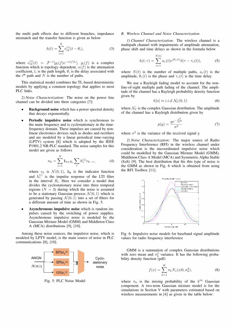
• Periodic impulsive noise which is synchronous tothe main frequency and is cyclostationary in the time-frequency domain. These impulses are caused by non-linear electronics devices such as diodes and rectifiersand are modeled by a linear periodical time-varying(LPTV) system [8] which is adopted by the IEEEP1901.2 NB-PLC standard. The noise samples for thismodel are given as follows
nk =NX
i=1
1k2Ri
X
⌧
h(i)⌧ vk�⌧ , (4)
where vk is N (0, 1), 1k is the indicator functionand h
(i)⌧ is the impulse response of the LTI filter
in the interval Ri. Here we consider a model thatdivides the cyclostationary noise into three temporalregions (N = 3) during which the noise is assumedto be a stationary Gaussian process N (0, 1) which isgenerated by passing N (0, 1) into a set of filters fora different amount of time as shown in Fig. 5.
• Asynchronous impulsive noise which is random im-pulses caused by the switching of power supplies.Asynchronous impulsive noise is modeled by theGaussian Mixture Model (GMM) and Middleton ClassA (MCA) distributions [9], [10].
Among these noise sources, the impulsive noise, which ismodeled by LPTV model, is the main source of noise in PLCcommunications [8], [10].
Fig. 5: PLC Noise Model
B. Wireless Channel and Noise Characterization
1) Channel Characterization: The wireless channel is amultipath channel with impairments of amplitude attenuation,phase shift and time delays as shown in the formula below
h(t, ⌧) =
N(t)X
i=1
ar(t)ej✓
r
(t)�(⌧ � ⌧r(t)), (5)
where N(t) is the number of multiple paths, ar(t) is theamplitude, ✓r(t) is the phase and ⌧r(t) is the time delay.
We use a Rayleigh fading model to account for the non-line-of-sight multiple path fading of the channel. The ampli-tude of the channel has a Rayleigh probability density functiongiven by
h[n] ⇡ i.i.d NC(0, 1) (6)
where NC is the complex Gaussian distribution. The amplitudeof the channel has a Rayleigh distribution given by
p(y) =ye�
y
2
2�2
�2(7)
where �2 is the variance of the received signal y.
2) Noise Characterization: The major source of RadioFrequency Interference (RFI) in the wireless channel underconsideration is the uncoordinated impulsive noise whichcould be modelled by the Gaussian Mixture Model (GMM),Middleton Class A Model (MCA) and Symmetric Alpha Stable(SaS) [9]. The best distribution that fits this type of noise isthe GMM as shown in Fig. 6 which is obtained from usingthe RFI Toolbox [11].
Fig. 6: Impulsive noise models for baseband signal amplitudevalues for radio frequency interference
GMM is a summation of complex Gaussian distributionswith zero mean and �2
k variance. It has the following proba-bility density function (pdf)
f(x) =KX
k=1
⇡kNc(x|0,�2k), (8)
where ⇡k is the mixing probability of the kth Gaussiancomponent. A two-term Gaussian mixture model is for thesimulations in Section V with parameters estimated based onwireless measurements in [4] as given in the table below:
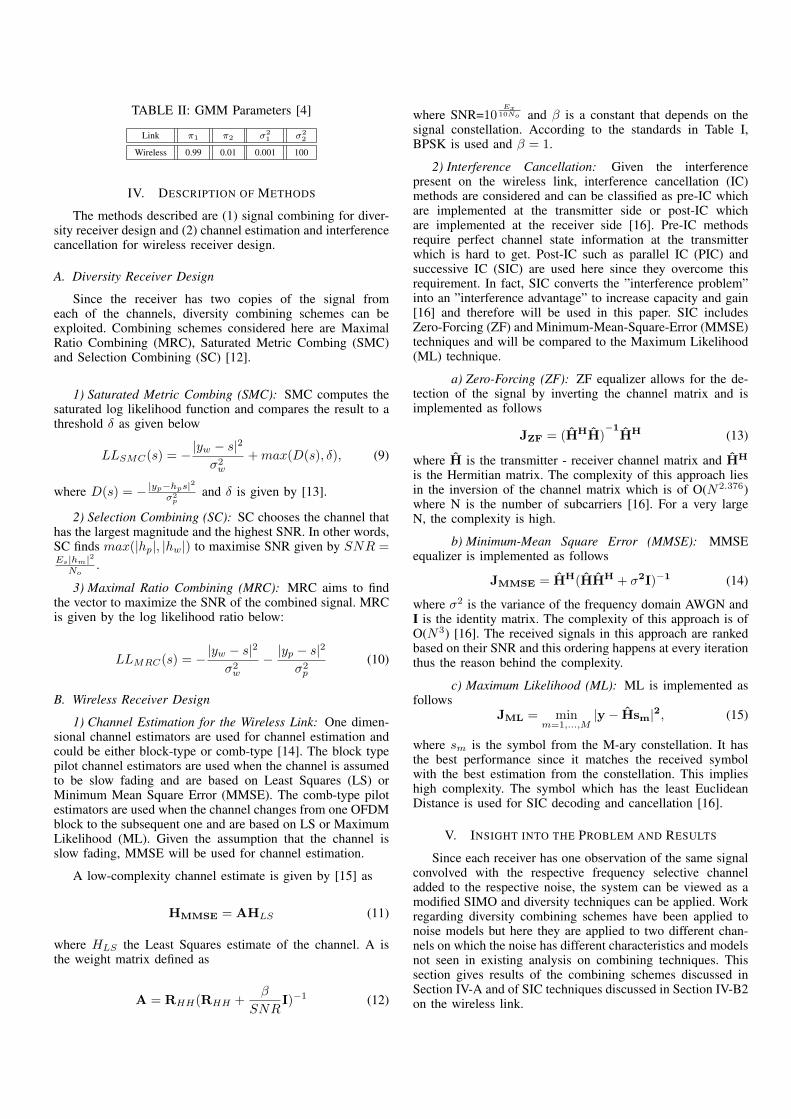
TABLE II: GMM Parameters [4]
Link ⇡1 ⇡2 �21 �2
2
Wireless 0.99 0.01 0.001 100
IV. DESCRIPTION OF METHODS
The methods described are (1) signal combining for diver-sity receiver design and (2) channel estimation and interferencecancellation for wireless receiver design.
A. Diversity Receiver Design
Since the receiver has two copies of the signal fromeach of the channels, diversity combining schemes can beexploited. Combining schemes considered here are MaximalRatio Combining (MRC), Saturated Metric Combing (SMC)and Selection Combining (SC) [12].
1) Saturated Metric Combing (SMC): SMC computes thesaturated log likelihood function and compares the result to athreshold � as given below
LLSMC(s) = � |yw � s|2
�2w
+max(D(s), �), (9)
where D(s) = � |yp
�hp
s|2�2p
and � is given by [13].
2) Selection Combining (SC): SC chooses the channel thathas the largest magnitude and the highest SNR. In other words,SC finds max(|hp|, |hw|) to maximise SNR given by SNR =E
s
|hm
|2N
o
.
3) Maximal Ratio Combining (MRC): MRC aims to findthe vector to maximize the SNR of the combined signal. MRCis given by the log likelihood ratio below:
LLMRC(s) = � |yw � s|2
�2w
� |yp � s|2
�2p
(10)
B. Wireless Receiver Design
1) Channel Estimation for the Wireless Link: One dimen-sional channel estimators are used for channel estimation andcould be either block-type or comb-type [14]. The block typepilot channel estimators are used when the channel is assumedto be slow fading and are based on Least Squares (LS) orMinimum Mean Square Error (MMSE). The comb-type pilotestimators are used when the channel changes from one OFDMblock to the subsequent one and are based on LS or MaximumLikelihood (ML). Given the assumption that the channel isslow fading, MMSE will be used for channel estimation.
A low-complexity channel estimate is given by [15] as
HMMSE = AHLS (11)
where HLS the Least Squares estimate of the channel. A isthe weight matrix defined as
A = RHH(RHH +�
SNRI)�1 (12)
where SNR=10E
x
10No and � is a constant that depends on the
signal constellation. According to the standards in Table I,BPSK is used and � = 1.
2) Interference Cancellation: Given the interferencepresent on the wireless link, interference cancellation (IC)methods are considered and can be classified as pre-IC whichare implemented at the transmitter side or post-IC whichare implemented at the receiver side [16]. Pre-IC methodsrequire perfect channel state information at the transmitterwhich is hard to get. Post-IC such as parallel IC (PIC) andsuccessive IC (SIC) are used here since they overcome thisrequirement. In fact, SIC converts the ”interference problem”into an ”interference advantage” to increase capacity and gain[16] and therefore will be used in this paper. SIC includesZero-Forcing (ZF) and Minimum-Mean-Square-Error (MMSE)techniques and will be compared to the Maximum Likelihood(ML) technique.
a) Zero-Forcing (ZF): ZF equalizer allows for the de-tection of the signal by inverting the channel matrix and isimplemented as follows
JZF = (HHH)�1
HH (13)
where H is the transmitter - receiver channel matrix and HH
is the Hermitian matrix. The complexity of this approach liesin the inversion of the channel matrix which is of O(N2.376)where N is the number of subcarriers [16]. For a very largeN, the complexity is high.
b) Minimum-Mean Square Error (MMSE): MMSEequalizer is implemented as follows
JMMSE = HH(HHH + �2I)�1 (14)
where �2 is the variance of the frequency domain AWGN andI is the identity matrix. The complexity of this approach is ofO(N3) [16]. The received signals in this approach are rankedbased on their SNR and this ordering happens at every iterationthus the reason behind the complexity.
c) Maximum Likelihood (ML): ML is implemented asfollows
JML = minm=1,...,M
|y � Hsm|2, (15)
where sm is the symbol from the M-ary constellation. It hasthe best performance since it matches the received symbolwith the best estimation from the constellation. This implieshigh complexity. The symbol which has the least EuclideanDistance is used for SIC decoding and cancellation [16].
V. INSIGHT INTO THE PROBLEM AND RESULTS
Since each receiver has one observation of the same signalconvolved with the respective frequency selective channeladded to the respective noise, the system can be viewed as amodified SIMO and diversity techniques can be applied. Workregarding diversity combining schemes have been applied tonoise models but here they are applied to two different chan-nels on which the noise has different characteristics and modelsnot seen in existing analysis on combining techniques. Thissection gives results of the combining schemes discussed inSection IV-A and of SIC techniques discussed in Section IV-B2on the wireless link.
A. Diversity Reception
Applying the combining schemes under the simulationconditions in Table III, we obtain the results in Figs. 7 and 8.
TABLE III: Parameters for Combining Schemes Simulation
FFT size (N) 128Cyclic Prefix length 26
Modulation BPSKNumber of Paths 5, 20
Combining Scheme SMC, SC, MRC
Fig. 7: Combining Schemes for a 20-path channel model asper Table III
Fig. 8: Combining Schemes for a 5-path channel model as perTable III
As seen in Figs. 7 and 8, MRC performs best for thecombining of the two channels under the chosen noise models.As the number of multi paths increases, SMC starts to give aperformance close to MRC.
B. Wireless Receiver Simulations
Results of simulations under the parameters given in Ta-ble IV for a pure wireless channel are given in Figs. 10 and 11.
TABLE IV: Parameters for SIC Simulation on Wireless Link
Channel MultipathChannel Model RayleighChannel Taps 6
GMM parameters [0.99, 0.001] and [0.01, 100]FFT size (N) 128
Cyclic Prefix length 26Modulation BPSK
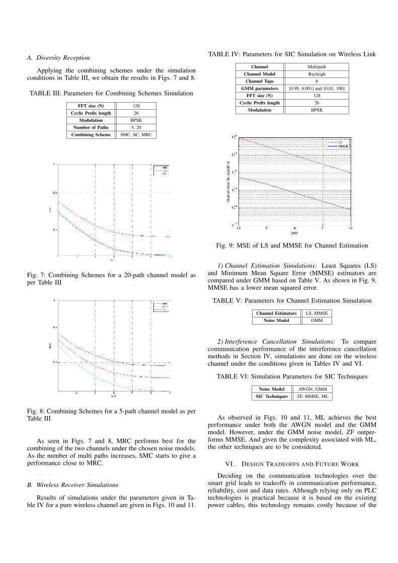
Fig. 9: MSE of LS and MMSE for Channel Estimation
1) Channel Estimation Simulations: Least Squares (LS)and Minimum Mean Square Error (MMSE) estimators arecompared under GMM based on Table V. As shown in Fig. 9,MMSE has a lower mean squared error.
TABLE V: Parameters for Channel Estimation Simulation
Channel Estimators LS, MMSENoise Model GMM
2) Interference Cancellation Simulations: To comparecommunication performance of the interference cancellationmethods in Section IV, simulations are done on the wirelesschannel under the conditions given in Tables IV and VI.
TABLE VI: Simulation Parameters for SIC Techniques
Noise Model AWGN, GMMSIC Techniques ZF, MMSE, ML
As observed in Figs. 10 and 11, ML achieves the bestperformance under both the AWGN model and the GMMmodel. However, under the GMM noise model, ZF outper-forms MMSE. And given the complexity associated with ML,the other techniques are to be considered.
VI. DESIGN TRADEOFFS AND FUTURE WORK
Deciding on the communication technologies over thesmart grid leads to tradeoffs in communication performance,reliability, cost and data rates. Although relying only on PLCtechnologies is practical because it is based on the existingpower cables, this technology remains costly because of the
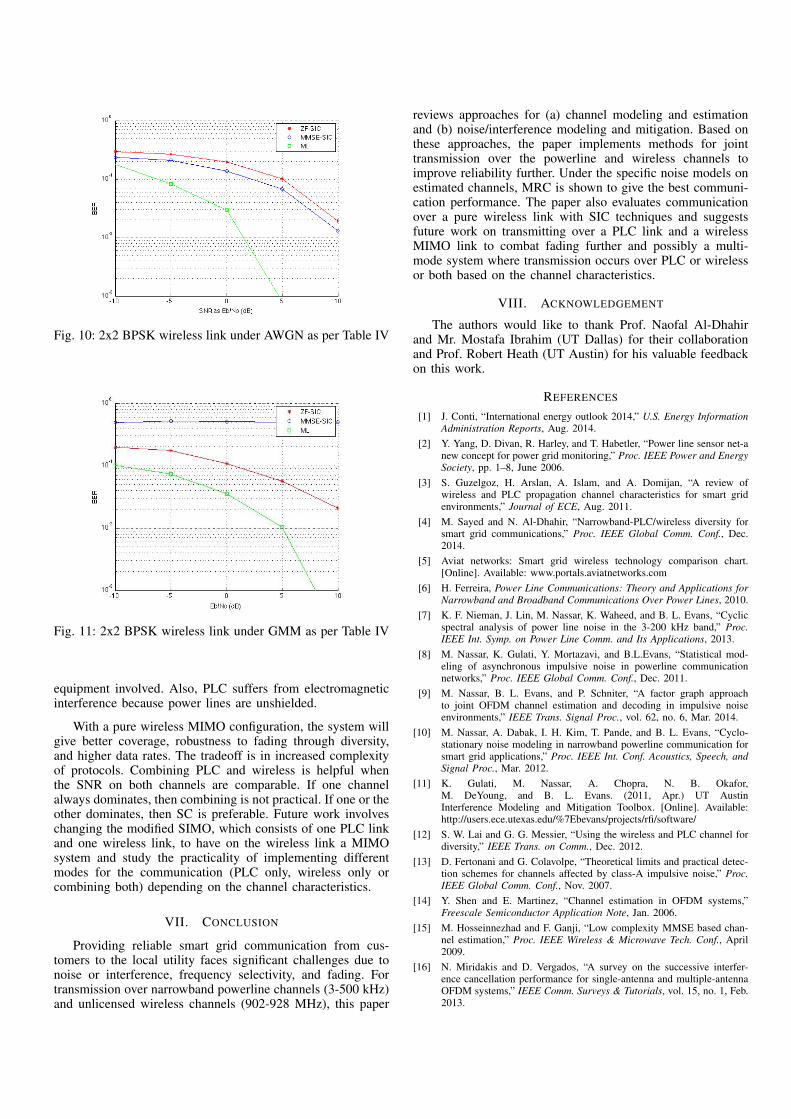
Fig. 10: 2x2 BPSK wireless link under AWGN as per Table IV
Fig. 11: 2x2 BPSK wireless link under GMM as per Table IV
equipment involved. Also, PLC suffers from electromagneticinterference because power lines are unshielded.
With a pure wireless MIMO configuration, the system willgive better coverage, robustness to fading through diversity,and higher data rates. The tradeoff is in increased complexityof protocols. Combining PLC and wireless is helpful whenthe SNR on both channels are comparable. If one channelalways dominates, then combining is not practical. If one or theother dominates, then SC is preferable. Future work involveschanging the modified SIMO, which consists of one PLC linkand one wireless link, to have on the wireless link a MIMOsystem and study the practicality of implementing differentmodes for the communication (PLC only, wireless only orcombining both) depending on the channel characteristics.
VII. CONCLUSION
Providing reliable smart grid communication from cus-tomers to the local utility faces significant challenges due tonoise or interference, frequency selectivity, and fading. Fortransmission over narrowband powerline channels (3-500 kHz)and unlicensed wireless channels (902-928 MHz), this paper
reviews approaches for (a) channel modeling and estimationand (b) noise/interference modeling and mitigation. Based onthese approaches, the paper implements methods for jointtransmission over the powerline and wireless channels toimprove reliability further. Under the specific noise models onestimated channels, MRC is shown to give the best communi-cation performance. The paper also evaluates communicationover a pure wireless link with SIC techniques and suggestsfuture work on transmitting over a PLC link and a wirelessMIMO link to combat fading further and possibly a multi-mode system where transmission occurs over PLC or wirelessor both based on the channel characteristics.
VIII. ACKNOWLEDGEMENT
The authors would like to thank Prof. Naofal Al-Dhahirand Mr. Mostafa Ibrahim (UT Dallas) for their collaborationand Prof. Robert Heath (UT Austin) for his valuable feedbackon this work.
REFERENCES
[1] J. Conti, “International energy outlook 2014,” U.S. Energy InformationAdministration Reports, Aug. 2014.
[2] Y. Yang, D. Divan, R. Harley, and T. Habetler, “Power line sensor net-anew concept for power grid monitoring,” Proc. IEEE Power and EnergySociety, pp. 1–8, June 2006.
[3] S. Guzelgoz, H. Arslan, A. Islam, and A. Domijan, “A review ofwireless and PLC propagation channel characteristics for smart gridenvironments,” Journal of ECE, Aug. 2011.
[4] M. Sayed and N. Al-Dhahir, “Narrowband-PLC/wireless diversity forsmart grid communications,” Proc. IEEE Global Comm. Conf., Dec.2014.
[5] Aviat networks: Smart grid wireless technology comparison chart.[Online]. Available: www.portals.aviatnetworks.com
[6] H. Ferreira, Power Line Communications: Theory and Applications forNarrowband and Broadband Communications Over Power Lines, 2010.
[7] K. F. Nieman, J. Lin, M. Nassar, K. Waheed, and B. L. Evans, “Cyclicspectral analysis of power line noise in the 3-200 kHz band,” Proc.IEEE Int. Symp. on Power Line Comm. and Its Applications, 2013.
[8] M. Nassar, K. Gulati, Y. Mortazavi, and B.L.Evans, “Statistical mod-eling of asynchronous impulsive noise in powerline communicationnetworks,” Proc. IEEE Global Comm. Conf., Dec. 2011.
[9] M. Nassar, B. L. Evans, and P. Schniter, “A factor graph approachto joint OFDM channel estimation and decoding in impulsive noiseenvironments,” IEEE Trans. Signal Proc., vol. 62, no. 6, Mar. 2014.
[10] M. Nassar, A. Dabak, I. H. Kim, T. Pande, and B. L. Evans, “Cyclo-stationary noise modeling in narrowband powerline communication forsmart grid applications,” Proc. IEEE Int. Conf. Acoustics, Speech, andSignal Proc., Mar. 2012.
[11] K. Gulati, M. Nassar, A. Chopra, N. B. Okafor,M. DeYoung, and B. L. Evans. (2011, Apr.) UT AustinInterference Modeling and Mitigation Toolbox. [Online]. Available:http://users.ece.utexas.edu/%7Ebevans/projects/rfi/software/
[12] S. W. Lai and G. G. Messier, “Using the wireless and PLC channel fordiversity,” IEEE Trans. on Comm., Dec. 2012.
[13] D. Fertonani and G. Colavolpe, “Theoretical limits and practical detec-tion schemes for channels affected by class-A impulsive noise,” Proc.IEEE Global Comm. Conf., Nov. 2007.
[14] Y. Shen and E. Martinez, “Channel estimation in OFDM systems,”Freescale Semiconductor Application Note, Jan. 2006.
[15] M. Hosseinnezhad and F. Ganji, “Low complexity MMSE based chan-nel estimation,” Proc. IEEE Wireless & Microwave Tech. Conf., April2009.
[16] N. Miridakis and D. Vergados, “A survey on the successive interfer-ence cancellation performance for single-antenna and multiple-antennaOFDM systems,” IEEE Comm. Surveys & Tutorials, vol. 15, no. 1, Feb.2013.