Embed Size (px)
Citation preview
Materials Sciences and Applications, 2011, 2, 319-330 doi:10.4236/msa.2011.25042 Published Online May 2011 (http://www.SciRP.org/journal/msa)
Copyright © 2011 SciRes. MSA
319
Design with Ultra Strong Polyethylene Fibers
Roelof Marissen1,2
1DSM Dyneema, Urmond, The Netherlands; 2Delft University of Technology, Faculty of Aerospace Engineering, Delft, The Nether-lands. Email: [email protected], [email protected] Received January 4th, 2011; revised March 11th, 2011, accepted March 23rd, 2011.
ABSTRACT
Ultra strong polyethylene fibers can be made by gel-spinning of Ultra High Molecular Weight Polyethylene (UHMWPE). Such fibers exhibit extraordinary properties. They show very high tensile strength and stiffness and low density. On the other hand, the axial and transverse compression strength is low. This is a large difference with other advanced fibers like glass and carbon fibers. Additionally, the fibers are chemically inert and the bonding strength to other materials like resins is weak. Moreover, the coefficient of friction is very low, so the fiber is extremely slippery. Another property is viscoelasticity; the fiber elongates due to creep at higher loads or temperatures. This exceptional combination of properties explains why gel-spun UHMWPE fibers are not always applied in straight forward ways, e.g. like glass and carbon fibers in composites. On the other hand, weaknesses like the limited compression strength are related to very damage tolerant behavior on a micro scale. This opened application areas like providing of cut resistance. This paper describes some established applications and shows the relationship between the properties and the applications. Fur- thermore, some emerging applications are discussed and it is demonstrated how weaknesses can be turned into advan- tages. Keywords: Tensile, Compression, Friction, Creep, Density, Impact
1. Introduction
Very strong fibers have found various applications in technology. Glass fibers were about the first non-metallic fibers with strength levels exceeding 2 GPa. Structural application of glass fibers in composites is well estab- lished. Such composites are lightweight and high-strength materials. Carbon fibers were developed later and are stronger, stiffer and lighter than glass fibers. Carbon fiber reinforced plastics are superior construction materials with unsurpassed specific strength. Polymer fibers could initially not reach strength levels that are comparable to glass and carbon fibers. However, solvent based spinning technologies enabled the development of ultra strong polymer fibers. Two classes of such fibers can be distin- guished. One class is based on rigid rod molecules. Well- known products are Kevlar®, Twaron® or Zylon®. The molecular chains of these fibers exhibit some bending stiffness. The other class is made of the very flexible polyethylene molecules. A well known trade name is Dyneema® from DSM. Spectra® is a similar fiber from Honeywell. The interaction between the polymer mo- lecular chains is low for polyethylene. Therefore, very long chains are necessary to provide sufficient load
transfer between the macromolecules. Such a polyethy- lene with long chains is called Ultra High Molecular Weight Polyethylene (UHMWPE). The gel spinning process starts from a high temperature solution of UHM- WPE. Cooling causes crystallization from the solution, thus a gel is obtained, containing polymer crystals and solution. These crystals contain disentangled molecular chains. The disentanglement is conserved during the re- moval of the solvent. These disentangled chains can be unravelled during a subsequent drawing process. The drawing ratio is very high (about 100) and thus causes extreme orientation of the UHMWPE chains. The paral- lel oriented chains are again arranged in a crystalline configuration. The crystallinity is high. Demco et al. [1] analyzed various phases with NMR. Roughly summa- rized about 90% of the fiber material is crystalline. The longitudinal chain orientation “translates” external ten- sion loads to loads on the strong covalent bonds between the carbon atoms of the chains, and this explains the high tensile strength of the fibers. More detailed information on the production and properties of such fibers is des- cribed in earlier publications, e.g. by Smith and Lemstra [2], and Jacobs [3]. An early application field that was anticipated during the development of these very strong
Design with Ultra Strong Polyethylene Fibers
Copyright © 2011 SciRes. MSA
320
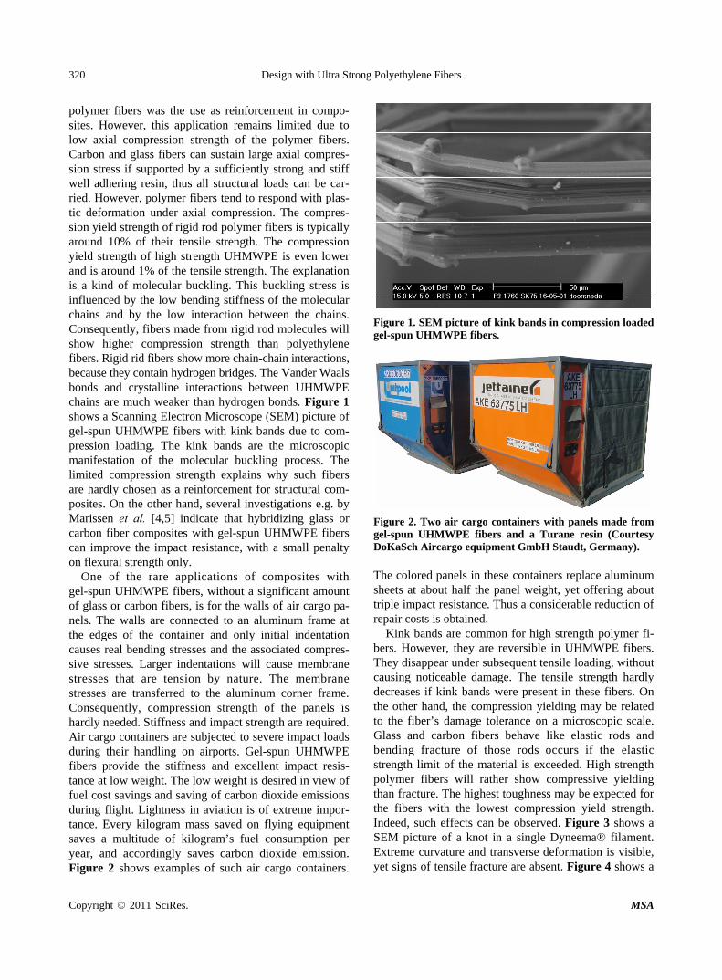
polymer fibers was the use as reinforcement in compo- sites. However, this application remains limited due to low axial compression strength of the polymer fibers. Carbon and glass fibers can sustain large axial compres- sion stress if supported by a sufficiently strong and stiff well adhering resin, thus all structural loads can be car- ried. However, polymer fibers tend to respond with plas- tic deformation under axial compression. The compres- sion yield strength of rigid rod polymer fibers is typically around 10% of their tensile strength. The compression yield strength of high strength UHMWPE is even lower and is around 1% of the tensile strength. The explanation is a kind of molecular buckling. This buckling stress is influenced by the low bending stiffness of the molecular chains and by the low interaction between the chains. Consequently, fibers made from rigid rod molecules will show higher compression strength than polyethylene fibers. Rigid rid fibers show more chain-chain interactions, because they contain hydrogen bridges. The Vander Waals bonds and crystalline interactions between UHMWPE chains are much weaker than hydrogen bonds. Figure 1 shows a Scanning Electron Microscope (SEM) picture of gel-spun UHMWPE fibers with kink bands due to com- pression loading. The kink bands are the microscopic manifestation of the molecular buckling process. The limited compression strength explains why such fibers are hardly chosen as a reinforcement for structural com- posites. On the other hand, several investigations e.g. by Marissen et al. [4,5] indicate that hybridizing glass or carbon fiber composites with gel-spun UHMWPE fibers can improve the impact resistance, with a small penalty on flexural strength only.
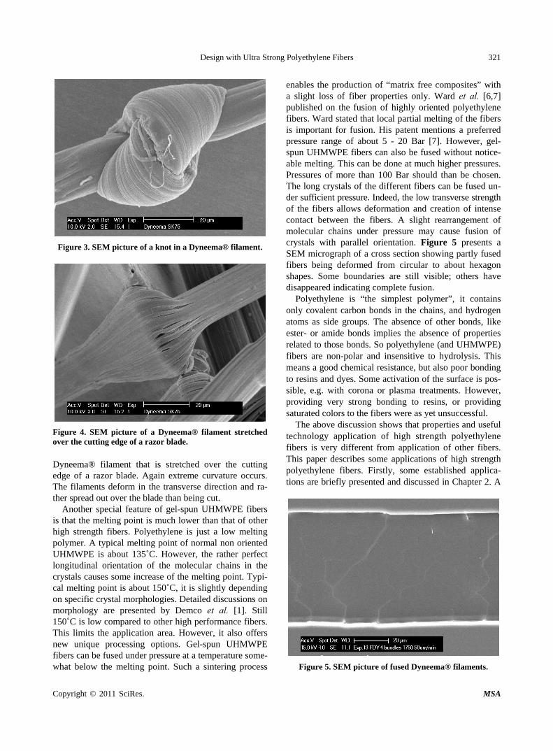
One of the rare applications of composites with gel-spun UHMWPE fibers, without a significant amount of glass or carbon fibers, is for the walls of air cargo pa-nels. The walls are connected to an aluminum frame at the edges of the container and only initial indentation causes real bending stresses and the associated compres- sive stresses. Larger indentations will cause membrane stresses that are tension by nature. The membrane stresses are transferred to the aluminum corner frame. Consequently, compression strength of the panels is hardly needed. Stiffness and impact strength are required. Air cargo containers are subjected to severe impact loads during their handling on airports. Gel-spun UHMWPE fibers provide the stiffness and excellent impact resis- tance at low weight. The low weight is desired in view of fuel cost savings and saving of carbon dioxide emissions during flight. Lightness in aviation is of extreme impor- tance. Every kilogram mass saved on flying equipment saves a multitude of kilogram’s fuel consumption per year, and accordingly saves carbon dioxide emission. Figure 2 shows examples of such air cargo containers.
Figure 1. SEM picture of kink bands in compression loaded gel-spun UHMWPE fibers.
Figure 2. Two air cargo containers with panels made from gel-spun UHMWPE fibers and a Turane resin (Courtesy DoKaSch Aircargo equipment GmbH Staudt, Germany). The colored panels in these containers replace aluminum sheets at about half the panel weight, yet offering about triple impact resistance. Thus a considerable reduction of repair costs is obtained.
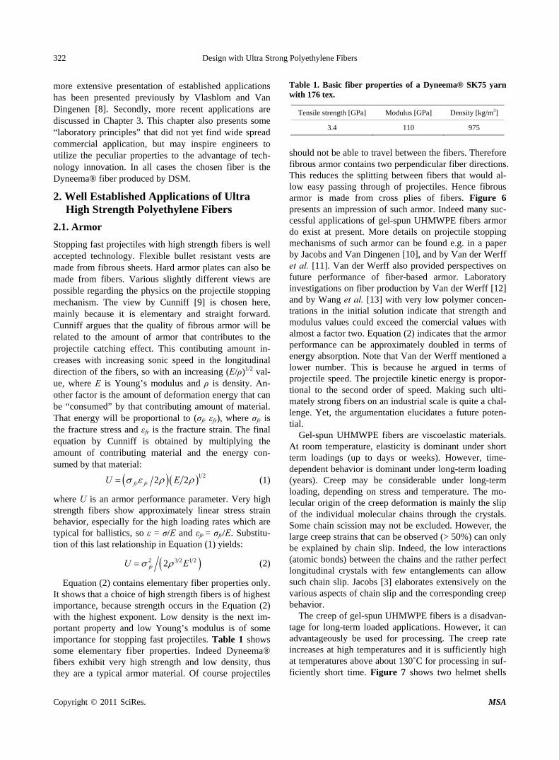
Kink bands are common for high strength polymer fi- bers. However, they are reversible in UHMWPE fibers. They disappear under subsequent tensile loading, without causing noticeable damage. The tensile strength hardly decreases if kink bands were present in these fibers. On the other hand, the compression yielding may be related to the fiber’s damage tolerance on a microscopic scale. Glass and carbon fibers behave like elastic rods and bending fracture of those rods occurs if the elastic strength limit of the material is exceeded. High strength polymer fibers will rather show compressive yielding than fracture. The highest toughness may be expected for the fibers with the lowest compression yield strength. Indeed, such effects can be observed. Figure 3 shows a SEM picture of a knot in a single Dyneema® filament. Extreme curvature and transverse deformation is visible, yet signs of tensile fracture are absent. Figure 4 shows a
Design with Ultra Strong Polyethylene Fibers
Copyright © 2011 SciRes. MSA
321
Figure 3. SEM picture of a knot in a Dyneema® filament.
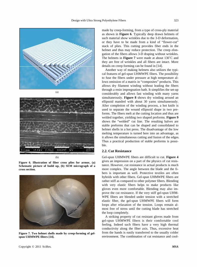
Figure 4. SEM picture of a Dyneema® filament stretched over the cutting edge of a razor blade. Dyneema® filament that is stretched over the cutting edge of a razor blade. Again extreme curvature occurs. The filaments deform in the transverse direction and ra-ther spread out over the blade than being cut.
Another special feature of gel-spun UHMWPE fibers is that the melting point is much lower than that of other high strength fibers. Polyethylene is just a low melting polymer. A typical melting point of normal non oriented UHMWPE is about 135˚C. However, the rather perfect longitudinal orientation of the molecular chains in the crystals causes some increase of the melting point. Typi- cal melting point is about 150˚C, it is slightly depending on specific crystal morphologies. Detailed discussions on morphology are presented by Demco et al. [1]. Still 150˚C is low compared to other high performance fibers. This limits the application area. However, it also offers new unique processing options. Gel-spun UHMWPE fibers can be fused under pressure at a temperature some- what below the melting point. Such a sintering process
enables the production of “matrix free composites” with a slight loss of fiber properties only. Ward et al. [6,7] published on the fusion of highly oriented polyethylene fibers. Ward stated that local partial melting of the fibers is important for fusion. His patent mentions a preferred pressure range of about 5 - 20 Bar [7]. However, gel- spun UHMWPE fibers can also be fused without notice- able melting. This can be done at much higher pressures. Pressures of more than 100 Bar should than be chosen. The long crystals of the different fibers can be fused un- der sufficient pressure. Indeed, the low transverse strength of the fibers allows deformation and creation of intense contact between the fibers. A slight rearrangement of molecular chains under pressure may cause fusion of crystals with parallel orientation. Figure 5 presents a SEM micrograph of a cross section showing partly fused fibers being deformed from circular to about hexagon shapes. Some boundaries are still visible; others have disappeared indicating complete fusion.
Polyethylene is “the simplest polymer”, it contains only covalent carbon bonds in the chains, and hydrogen atoms as side groups. The absence of other bonds, like ester- or amide bonds implies the absence of properties related to those bonds. So polyethylene (and UHMWPE) fibers are non-polar and insensitive to hydrolysis. This means a good chemical resistance, but also poor bonding to resins and dyes. Some activation of the surface is pos- sible, e.g. with corona or plasma treatments. However, providing very strong bonding to resins, or providing saturated colors to the fibers were as yet unsuccessful.
The above discussion shows that properties and useful technology application of high strength polyethylene fibers is very different from application of other fibers. This paper describes some applications of high strength polyethylene fibers. Firstly, some established applica- tions are briefly presented and discussed in Chapter 2. A
Figure 5. SEM picture of fused Dyneema® filaments.
Design with Ultra Strong Polyethylene Fibers
Copyright © 2011 SciRes. MSA
322
more extensive presentation of established applications has been presented previously by Vlasblom and Van Dingenen [8]. Secondly, more recent applications are discussed in Chapter 3. This chapter also presents some “laboratory principles” that did not yet find wide spread commercial application, but may inspire engineers to utilize the peculiar properties to the advantage of tech- nology innovation. In all cases the chosen fiber is the Dyneema® fiber produced by DSM.
2. Well Established Applications of Ultra High Strength Polyethylene Fibers
2.1. Armor
Stopping fast projectiles with high strength fibers is well accepted technology. Flexible bullet resistant vests are made from fibrous sheets. Hard armor plates can also be made from fibers. Various slightly different views are possible regarding the physics on the projectile stopping mechanism. The view by Cunniff [9] is chosen here, mainly because it is elementary and straight forward. Cunniff argues that the quality of fibrous armor will be related to the amount of armor that contributes to the projectile catching effect. This contibuting amount in- creases with increasing sonic speed in the longitudinal direction of the fibers, so with an increasing (E/ρ)1/2 val-ue, where E is Young’s modulus and ρ is density. An- other factor is the amount of deformation energy that can be “consumed” by that contributing amount of material. That energy will be proportional to (σfr εfr), where σfr is the fracture stress and εfr is the fracture strain. The final equation by Cunniff is obtained by multiplying the amount of contributing material and the energy con- sumed by that material:
1 22 2fr frU E (1)
where U is an armor performance parameter. Very high strength fibers show approximately linear stress strain behavior, especially for the high loading rates which are typical for ballistics, so ε = σ/E and εfr = σfr/E. Substitu- tion of this last relationship in Equation (1) yields:
2 3 2 1 22frU E (2)
Equation (2) contains elementary fiber properties only. It shows that a choice of high strength fibers is of highest importance, because strength occurs in the Equation (2) with the highest exponent. Low density is the next im-portant property and low Young’s modulus is of some importance for stopping fast projectiles. Table 1 shows some elementary fiber properties. Indeed Dyneema® fibers exhibit very high strength and low density, thus they are a typical armor material. Of course projectiles
Table 1. Basic fiber properties of a Dyneema® SK75 yarn with 176 tex.
Tensile strength [GPa] Modulus [GPa] Density [kg/m3]
3.4 110 975
should not be able to travel between the fibers. Therefore fibrous armor contains two perpendicular fiber directions. This reduces the splitting between fibers that would al-low easy passing through of projectiles. Hence fibrous armor is made from cross plies of fibers. Figure 6 presents an impression of such armor. Indeed many suc-cessful applications of gel-spun UHMWPE fibers armor do exist at present. More details on projectile stopping mechanisms of such armor can be found e.g. in a paper by Jacobs and Van Dingenen [10], and by Van der Werff et al. [11]. Van der Werff also provided perspectives on future performance of fiber-based armor. Laboratory investigations on fiber production by Van der Werff [12] and by Wang et al. [13] with very low polymer concen-trations in the initial solution indicate that strength and modulus values could exceed the comercial values with almost a factor two. Equation (2) indicates that the armor performance can be approximately doubled in terms of energy absorption. Note that Van der Werff mentioned a lower number. This is because he argued in terms of projectile speed. The projectile kinetic energy is propor-tional to the second order of speed. Making such ulti-mately strong fibers on an industrial scale is quite a chal-lenge. Yet, the argumentation elucidates a future poten-tial.
Gel-spun UHMWPE fibers are viscoelastic materials. At room temperature, elasticity is dominant under short term loadings (up to days or weeks). However, time- dependent behavior is dominant under long-term loading (years). Creep may be considerable under long-term loading, depending on stress and temperature. The mo- lecular origin of the creep deformation is mainly the slip of the individual molecular chains through the crystals. Some chain scission may not be excluded. However, the large creep strains that can be observed (> 50%) can only be explained by chain slip. Indeed, the low interactions (atomic bonds) between the chains and the rather perfect longitudinal crystals with few entanglements can allow such chain slip. Jacobs [3] elaborates extensively on the various aspects of chain slip and the corresponding creep behavior.
The creep of gel-spun UHMWPE fibers is a disadvan- tage for long-term loaded applications. However, it can advantageously be used for processing. The creep rate increases at high temperatures and it is sufficiently high at temperatures above about 130˚C for processing in suf- ficiently short time. Figure 7 shows two helmet shells
Design with Ultra Strong Polyethylene Fibers
Copyright © 2011 SciRes. MSA
323
(a)
(b)
Figure 6. Illustration of fiber cross plies for armor, (a) Schematic picture of build up, (b) SEM micrograph of a cross section.
Figure 7. Two helmet shells made by creep-forming of gel- spun UHMWPE fibers [14].
made by creep-forming, from a type of cross-ply material as shown in Figure 6. Typically deep drawn helmets of such material show wrinkles due to the 3-D deformation, or they have to be made from a kind of “flower-cut” stack of plies. This cutting provides fiber ends in the helmet and thus may reduce protection. The creep elon- gation of the fibers allows 3-D draping without wrinkles. The helmets in Figure 7 were made at about 130˚C and they are free of wrinkles and all fibers are intact. More details on creep forming can be found in [14].
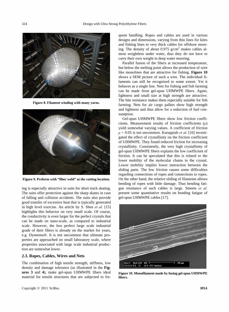
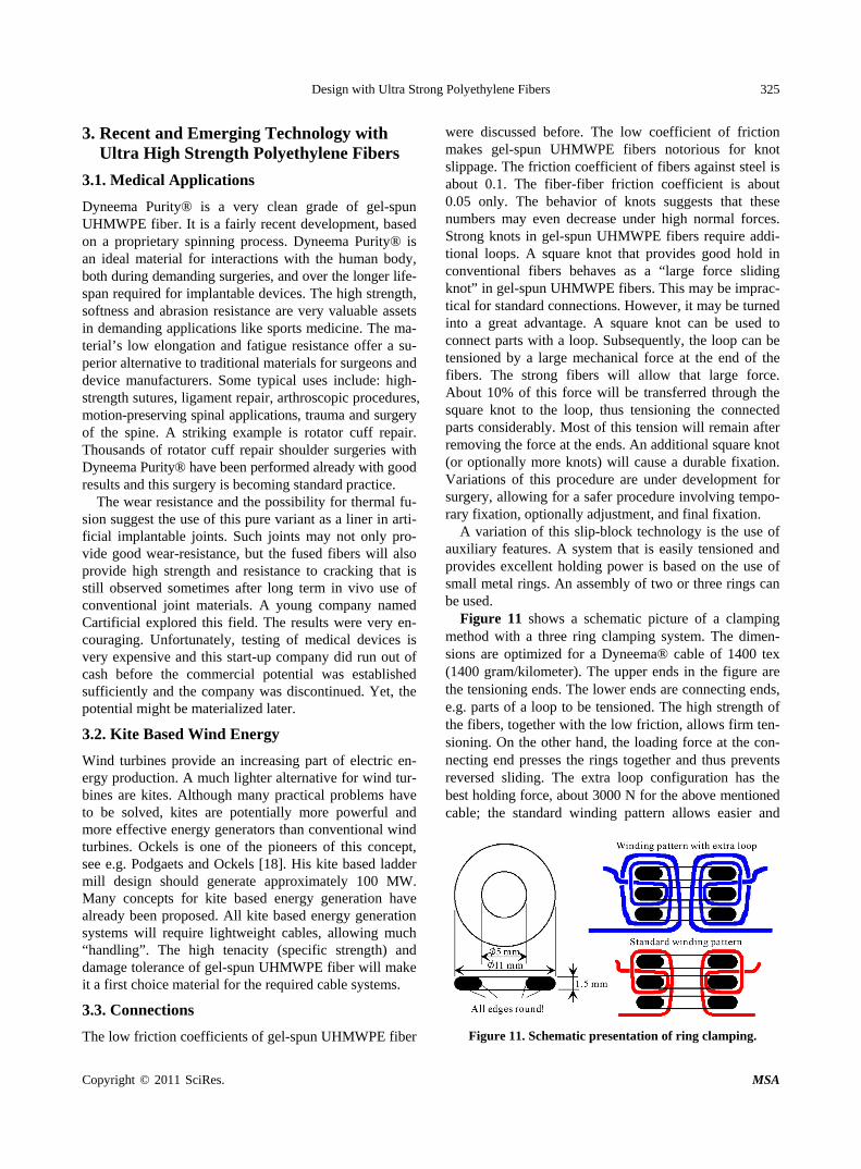
Another way of making helmets also utilizes the typi- cal features of gel-spun UHMWPE fibers. The possibility to fuse the fibers under pressure at high temperature al- lows omission of a matrix in “composites” products. This allows dry filament winding without leading the fibers through a resin impregnation bath. It simplifies the set-up considerably and allows fast winding with many yarns simultaneously. Figure 8 shows dry winding around an ellipsoid mandrel with about 30 yarns simultaneously. After completion of the winding process, a hot knife is used to separate the wound ellipsoid shape in two pre- forms. The fibers melt at the cutting location and thus are welded together, yielding two shaped preforms. Figure 9 shows the “welded” cut line. The resulting halves are stable preforms that can be shaped and consolidated to helmet shells in a hot press. The disadvantage of the low melting temperature is turned here into an advantage, as it allows the simultaneous cutting and fusion of the edges. Thus a practical production of stable preforms is possi- ble.
2.2. Cut Resistance
Gel-spun UHMWPE fibers are difficult to cut. Figure 4 gives an impression on a part of the physics of cut resis- tance. However, cut resistance in actual products is much more complex. The angle between the blade and the fi- bers is important as well. Protective textiles are often hybrids with other fibers. Gel-spun UHMWPE fibers are rather stiff as compared to other polymer fibers. Blending with very elastic fibers helps to make products like gloves even more comfortable. Blending may also im- prove the cut resistance. If the very stiff gel-spun UHM- WPE fibers are blended under tension with a stretched elastic fiber, the gel-spun UHMWPE fibers will form loops after relaxation of the tension. Loops remain al- most free of stress until the cutting blade has stretched the loop completely.
A striking property of cut resistant gloves made from gel-spun UHMWPE fibers is their comfortable cool feeling. Indeed such fibers have a very high thermal conductivity along the fiber axis. Thus, excessive heat from the hands is easily transferred to the usually colder environment. The combination of cut resistance and cool-
Design with Ultra Strong Polyethylene Fibers
Copyright © 2011 SciRes. MSA
324
Figure 8. Filament winding with many yarns.
Figure 9. Preform with “fiber weld” at the cutting location. ing is especially attractive in suits for short track skating. The suits offer protection against the sharp skates in case of falling and collision accidents. The suits also provide good transfer of excessive heat that is typically generated in high level exercise. An article by S. Shen et al. [15] highlights this behavior on very small scale. Of course, the conductivity is even larger for the perfect crystals that can be made on nano-scale, as compared to industrial scale. However, the less perfect large scale industrial grade of their fibers is already on the market for years, e.g. Dyneema®. It is not uncommon that ultimate pro- perties are approached on small laboratory scale, where properties associated with large scale industrial produc- tion are somewhat lower.
2.3. Ropes, Cables, Wires and Nets
The combination of high tensile strength, stiffness, low density and damage tolerance (as illustrated in the Fig-ures 3 and 4), make gel-spun UHMWPE fibers ideal material for tensile structures that are subjected to fre-
quent handling. Ropes and cables are used in various designs and dimensions, varying from thin lines for kites and fishing lines to very thick cables for offshore moor-ing. The density of about 0.975 g/cm3 makes cables al-most weightless under water, thus they do not have to carry their own weight in deep water mooring.
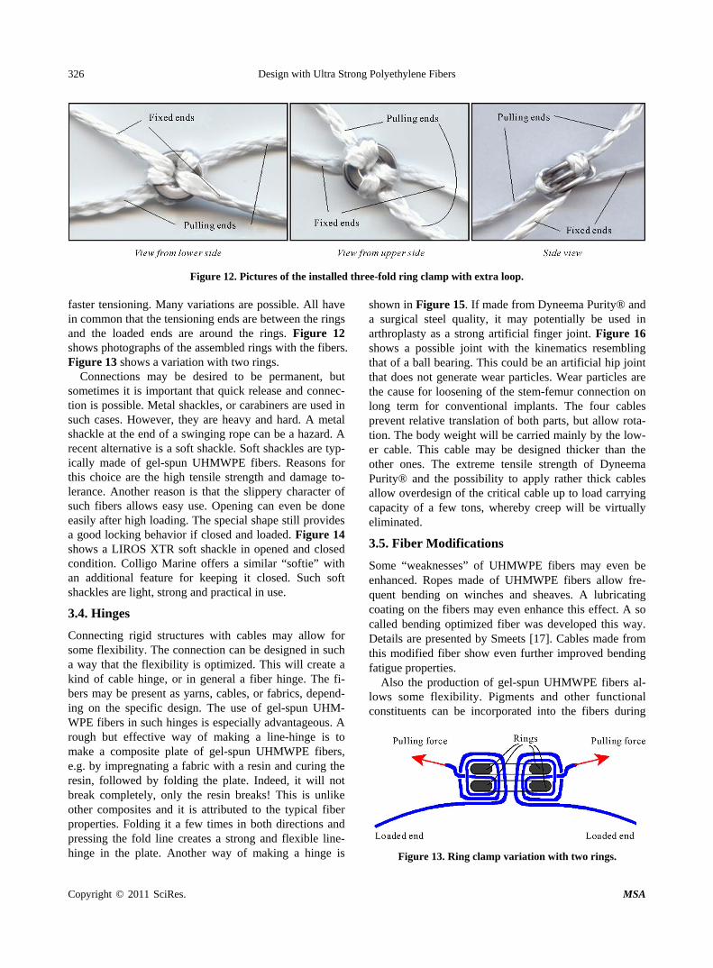
Parallel fusion of the fibers at increased temperature, but below the melting point allows the production of wire like monolines that are attractive for fishing. Figure 10 shows a SEM picture of such a wire. The individual fi-laments can still be recognized to some extent. Yet it behaves as a single line. Nets for fishing and fish farming can be made from gel-spun UHMWPE fibers. Again, lightness and small size at high strength are attractive. The bite resistance makes them especially suitable for fish farming. Nets for air cargo pallets show high strength and lightness and thus allow for a reduction of fuel con-sumption.
Gel-spun UHMWPE fibers show low friction coeffi- cients. Measurement results of friction coefficients (μ) yield somewhat varying values. A coefficient of friction μ = 0.05 is not uncommon. Karuppiah et al. [16] investi-gated the effect of crystallinity on the friction coefficient of UHMWPE. They found reduced friction for increasing crystallinity. Consistently, the very high crystallinity of gel-spun UHMWPE fibers explains the low coefficient of friction. It can be speculated that this is related to the lower mobility of the molecular chains in the crystal. Lower mobility implies lower interaction between the sliding parts. The low friction causes some difficulties regarding connections of ropes and connections to ropes. On the other hand, the relative sliding of filaments allows bending of ropes with little damage. Thus bending fati-gue resistance of such cables is large. Smeets et al. present some quantitative results on bending fatigue of gel-spun UHMWPE cables [17].
Figure 10. Monofilament made by fusing gel-spun UHMWPE fibers.
Design with Ultra Strong Polyethylene Fibers
Copyright © 2011 SciRes. MSA
325
3. Recent and Emerging Technology with Ultra High Strength Polyethylene Fibers
3.1. Medical Applications
Dyneema Purity® is a very clean grade of gel-spun UHMWPE fiber. It is a fairly recent development, based on a proprietary spinning process. Dyneema Purity® is an ideal material for interactions with the human body, both during demanding surgeries, and over the longer life- span required for implantable devices. The high strength, softness and abrasion resistance are very valuable assets in demanding applications like sports medicine. The ma- terial’s low elongation and fatigue resistance offer a su- perior alternative to traditional materials for surgeons and device manufacturers. Some typical uses include: high- strength sutures, ligament repair, arthroscopic procedures, motion-preserving spinal applications, trauma and surgery of the spine. A striking example is rotator cuff repair. Thousands of rotator cuff repair shoulder surgeries with Dyneema Purity® have been performed already with good results and this surgery is becoming standard practice.
The wear resistance and the possibility for thermal fu- sion suggest the use of this pure variant as a liner in arti- ficial implantable joints. Such joints may not only pro- vide good wear-resistance, but the fused fibers will also provide high strength and resistance to cracking that is still observed sometimes after long term in vivo use of conventional joint materials. A young company named Cartificial explored this field. The results were very en- couraging. Unfortunately, testing of medical devices is very expensive and this start-up company did run out of cash before the commercial potential was established sufficiently and the company was discontinued. Yet, the potential might be materialized later.
3.2. Kite Based Wind Energy
Wind turbines provide an increasing part of electric en- ergy production. A much lighter alternative for wind tur- bines are kites. Although many practical problems have to be solved, kites are potentially more powerful and more effective energy generators than conventional wind turbines. Ockels is one of the pioneers of this concept, see e.g. Podgaets and Ockels [18]. His kite based ladder mill design should generate approximately 100 MW. Many concepts for kite based energy generation have already been proposed. All kite based energy generation systems will require lightweight cables, allowing much “handling”. The high tenacity (specific strength) and damage tolerance of gel-spun UHMWPE fiber will make it a first choice material for the required cable systems.
3.3. Connections
The low friction coefficients of gel-spun UHMWPE fiber
were discussed before. The low coefficient of friction makes gel-spun UHMWPE fibers notorious for knot slippage. The friction coefficient of fibers against steel is about 0.1. The fiber-fiber friction coefficient is about 0.05 only. The behavior of knots suggests that these numbers may even decrease under high normal forces. Strong knots in gel-spun UHMWPE fibers require addi-tional loops. A square knot that provides good hold in conventional fibers behaves as a “large force sliding knot” in gel-spun UHMWPE fibers. This may be imprac-tical for standard connections. However, it may be turned into a great advantage. A square knot can be used to connect parts with a loop. Subsequently, the loop can be tensioned by a large mechanical force at the end of the fibers. The strong fibers will allow that large force. About 10% of this force will be transferred through the square knot to the loop, thus tensioning the connected parts considerably. Most of this tension will remain after removing the force at the ends. An additional square knot (or optionally more knots) will cause a durable fixation. Variations of this procedure are under development for surgery, allowing for a safer procedure involving tempo-rary fixation, optionally adjustment, and final fixation.
A variation of this slip-block technology is the use of auxiliary features. A system that is easily tensioned and provides excellent holding power is based on the use of small metal rings. An assembly of two or three rings can be used.
Figure 11 shows a schematic picture of a clamping method with a three ring clamping system. The dimen-sions are optimized for a Dyneema® cable of 1400 tex (1400 gram/kilometer). The upper ends in the figure are the tensioning ends. The lower ends are connecting ends, e.g. parts of a loop to be tensioned. The high strength of the fibers, together with the low friction, allows firm ten-sioning. On the other hand, the loading force at the con-necting end presses the rings together and thus prevents reversed sliding. The extra loop configuration has the best holding force, about 3000 N for the above mentioned cable; the standard winding pattern allows easier and
Figure 11. Schematic presentation of ring clamping.
Design with Ultra Strong Polyethylene Fibers
Copyright © 2011 SciRes. MSA
326
Figure 12. Pictures of the installed three-fold ring clamp with extra loop. faster tensioning. Many variations are possible. All have in common that the tensioning ends are between the rings and the loaded ends are around the rings. Figure 12 shows photographs of the assembled rings with the fibers. Figure 13 shows a variation with two rings.
Connections may be desired to be permanent, but sometimes it is important that quick release and connec-tion is possible. Metal shackles, or carabiners are used in such cases. However, they are heavy and hard. A metal shackle at the end of a swinging rope can be a hazard. A recent alternative is a soft shackle. Soft shackles are typ-ically made of gel-spun UHMWPE fibers. Reasons for this choice are the high tensile strength and damage to-lerance. Another reason is that the slippery character of such fibers allows easy use. Opening can even be done easily after high loading. The special shape still provides a good locking behavior if closed and loaded. Figure 14 shows a LIROS XTR soft shackle in opened and closed condition. Colligo Marine offers a similar “softie” with an additional feature for keeping it closed. Such soft shackles are light, strong and practical in use.
3.4. Hinges
Connecting rigid structures with cables may allow for some flexibility. The connection can be designed in such a way that the flexibility is optimized. This will create a kind of cable hinge, or in general a fiber hinge. The fi-bers may be present as yarns, cables, or fabrics, depend-ing on the specific design. The use of gel-spun UHM- WPE fibers in such hinges is especially advantageous. A rough but effective way of making a line-hinge is to make a composite plate of gel-spun UHMWPE fibers, e.g. by impregnating a fabric with a resin and curing the resin, followed by folding the plate. Indeed, it will not break completely, only the resin breaks! This is unlike other composites and it is attributed to the typical fiber properties. Folding it a few times in both directions and pressing the fold line creates a strong and flexible line- hinge in the plate. Another way of making a hinge is
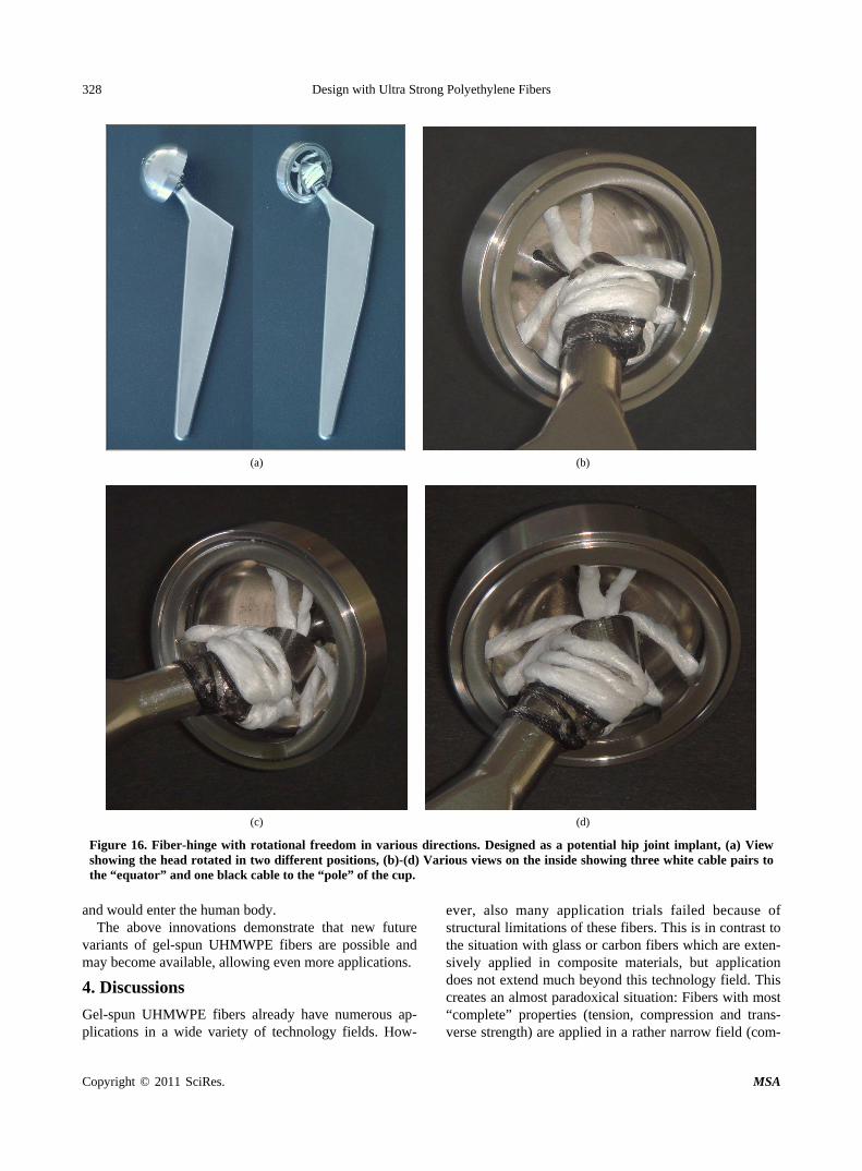
shown in Figure 15. If made from Dyneema Purity® and a surgical steel quality, it may potentially be used in arthroplasty as a strong artificial finger joint. Figure 16 shows a possible joint with the kinematics resembling that of a ball bearing. This could be an artificial hip joint that does not generate wear particles. Wear particles are the cause for loosening of the stem-femur connection on long term for conventional implants. The four cables prevent relative translation of both parts, but allow rota-tion. The body weight will be carried mainly by the low-er cable. This cable may be designed thicker than the other ones. The extreme tensile strength of Dyneema Purity® and the possibility to apply rather thick cables allow overdesign of the critical cable up to load carrying capacity of a few tons, whereby creep will be virtually eliminated.
3.5. Fiber Modifications
Some “weaknesses” of UHMWPE fibers may even be enhanced. Ropes made of UHMWPE fibers allow fre-quent bending on winches and sheaves. A lubricating coating on the fibers may even enhance this effect. A so called bending optimized fiber was developed this way. Details are presented by Smeets [17]. Cables made from this modified fiber show even further improved bending fatigue properties.
Also the production of gel-spun UHMWPE fibers al-lows some flexibility. Pigments and other functional constituents can be incorporated into the fibers during
Figure 13. Ring clamp variation with two rings.
Design with Ultra Strong Polyethylene Fibers
Copyright © 2011 SciRes. MSA
327
(a) (b)
(c) (d)
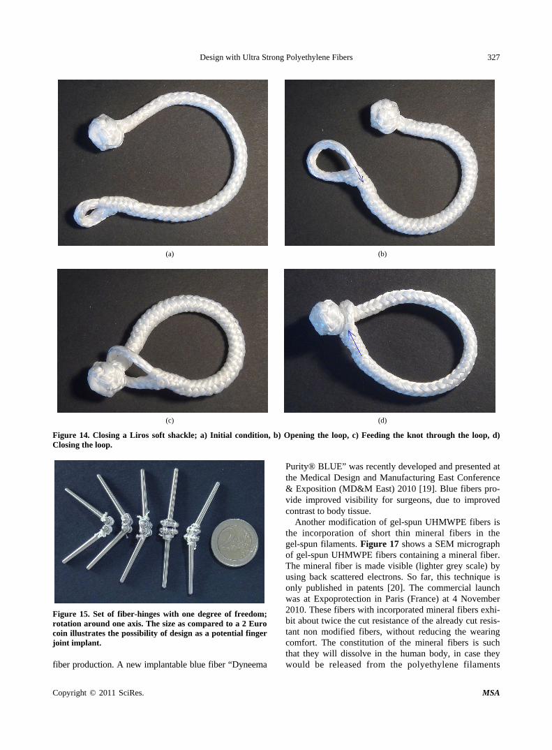
Figure 14. Closing a Liros soft shackle; a) Initial condition, b) Opening the loop, c) Feeding the knot through the loop, d) Closing the loop.
Figure 15. Set of fiber-hinges with one degree of freedom; rotation around one axis. The size as compared to a 2 Euro coin illustrates the possibility of design as a potential finger joint implant. fiber production. A new implantable blue fiber “Dyneema
Purity® BLUE” was recently developed and presented at the Medical Design and Manufacturing East Conference & Exposition (MD&M East) 2010 [19]. Blue fibers pro-vide improved visibility for surgeons, due to improved contrast to body tissue.
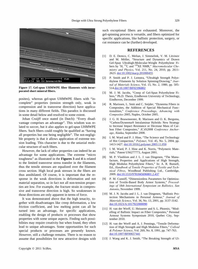
Another modification of gel-spun UHMWPE fibers is the incorporation of short thin mineral fibers in the gel-spun filaments. Figure 17 shows a SEM micrograph of gel-spun UHMWPE fibers containing a mineral fiber. The mineral fiber is made visible (lighter grey scale) by using back scattered electrons. So far, this technique is only published in patents [20]. The commercial launch was at Expoprotection in Paris (France) at 4 November 2010. These fibers with incorporated mineral fibers exhi-bit about twice the cut resistance of the already cut resis-tant non modified fibers, without reducing the wearing comfort. The constitution of the mineral fibers is such that they will dissolve in the human body, in case they would be released from the polyethylene filaments
Design with Ultra Strong Polyethylene Fibers
Copyright © 2011 SciRes. MSA
328
(a) (b)
(c) (d)
Figure 16. Fiber-hinge with rotational freedom in various directions. Designed as a potential hip joint implant, (a) View showing the head rotated in two different positions, (b)-(d) Various views on the inside showing three white cable pairs to the “equator” and one black cable to the “pole” of the cup.
and would enter the human body.
The above innovations demonstrate that new future variants of gel-spun UHMWPE fibers are possible and may become available, allowing even more applications.
4. Discussions
Gel-spun UHMWPE fibers already have numerous ap- plications in a wide variety of technology fields. How-
ever, also many application trials failed because of structural limitations of these fibers. This is in contrast to the situation with glass or carbon fibers which are exten- sively applied in composite materials, but application does not extend much beyond this technology field. This creates an almost paradoxical situation: Fibers with most “complete” properties (tension, compression and trans-verse strength) are applied in a rather narrow field (com-
Design with Ultra Strong Polyethylene Fibers
Copyright © 2011 SciRes. MSA
329
Figure 17. Gel-spun UHMWPE fiber filaments with incur- porated short mineral fibers. posites), whereas gel-spun UHMWPE fibers with “in- complete” properties (tension strength only, weak in compression and in transverse direction) have applica- tions in many different fields. This paradox is discussed in some detail below and resolved to some extent.
Johan Cruijff once stated (in Dutch): “Every disad-vantage comprises an advantage”. This wisdom was re-lated to soccer, but it also applies to gel-spun UHMWPE fibers. Such fibers could roughly be qualified as “having all properties but one being negligible”. The not-negligi- ble property is that it allows application of extreme ten-sion loading. This character is due to the uniaxial mole-cular structure of such fibers.
However, the lack of other properties can indeed be an advantage for some applications. The extreme “micro toughness” as illustrated in the Figures 3 and 4 is related to the limited transverse stress transfer in the filaments, thus the tensile stresses are equalized over the filament cross section. High local peak stresses in the fibers are thus annihilated. Of course, it is important that the re-sponse in the weak directions is deformation and not material separation, so in fact not all non-tension proper-ties are low. For example, the fracture strain in compres-sive and transverse direction is high. So weaknesses in those directions are only apparent in terms of force.
It was demonstrated above that the high tenacity, to-gether with disadvantages like creep deformation, a low friction coefficient, and low melting point can all be turned into an advantage, for specific applications, enabling the design of products or processes that show properties with some unique aspects. Finding such possi-bilities may require creativity but when found, they often lead to unique advantages. Some opportunities for such special products or processes are presently known. However, still a challenge remains. There is no reason to assume that possibilities for new attractive designs with
such exceptional fibers are exhausted. Moreover, the gel-spinning process is versatile, and fibers optimized for specific applications, like ballistic protection, surgery, or cut resistance can be (further) developed.
REFERENCES
[1] D. E. Demco, C. Melian, J. Simmelink, V. M. Litvinov and M. Möller, “Structure and Dynamics of Drawn Gel-Spun Ultrahigh-Molecular-Weight Polyethylene Fi-bers by 1H, 13C and 129XE NMR,” Macromolecular Che-mistry and Physics, Vol. 211, No. 24, 2010, pp. 2611- 2623. doi:10.1002/macp.201000455
[2] P. Smith and P. J. Lemstra, “Ultrahigh Strength Polye-thylene Filaments by Solution Spinning/Drawing,” Jour-nal of Materials Science, Vol. 15, No. 2, 1980, pp. 505- 514.doi:10.1007/BF02396802
[3] M. J. M. Jacobs, “Creep of Gel-Spun Polyethylene Fi-bres,” Ph.D. Thesis, Eindhoven University of Technology, Eindhoven, December 1999.
[4] R. Marissen, L. Smit and C. Snijder, “Dyneema Fibers in Composites, the Addition of Special Mechanical Func-tionalities,” Conference Proceedings, Advancing with Composites 2005, Naples, October 2005.
[5] J. G. H. Bouwmeester, R. Marissen and O. K. Bergsma, “Carbon/Dyneema® Intralaminar Hybrids: New Strategy to Increase Impact Resistance or Decrease Mass of Car-bon Fiber Composites,” ICAS2008 Conference Anchor-age, Alaska, September 2008.
[6] I. M. Ward and P. J. Hine, “The Science and Technology of Hot Compaction,” Polymer, Vol. 45, No. 5, 2004, pp. 1413-1427. doi:10.1016/j.polymer.2003.11.050
[7] I. M. Ward, P. J. Hine and K. Norris, “Polymeric Mate-rials,” Patent US6277773, August 2001.
[8] M. P. Vlasblom and J. L. J. van Dingenen, “The Manu-facture, Properties and Applications of High Strength, High Modulus Polyethylene Fibers,” In: A. R. Bunsell, Ed., Handbook of Tensile Properties of Textile and Tech-nical Fibres, Woodhead Publishing Ltd., Cambridge, 2009. doi:10.1533/9781845696801.2.437
[9] P. M. Cunniff, “Dimensionless Parameters for Optimiza-tion of Textile-Based Body Armor Systems,” Proceed-ings of 18th International Symposium on Ballistics, San Antonio, November 1999.
[10] M. J. N. Jacobs and J. L. J. van Dingenen, “Ballistic Pro-tection Mechanisms in Personal Armour,” Journal of Materials Science, Vol. 36, No. 13, 2001, pp. 3137-3142. doi:10.1023/A:1017922000090
[11] H. van der Werff, U. Heisserer and S. L. Phoenix, “Mod-elling of Ballistic Impact on Fiber Composites,” Personal Armour Systems Symposium 2010, Quebec City, Sep-tember 2010.
[12] H. van der Werff and A. J. Pennings, “Tensile Deforma-tion of High Strength and High Modulus Fibers,” Colloid & Polymer Science, Vol. 269, No. 8, 1991, pp. 747-763. doi:10.1007/BF00657441
[13] J. Wang and K. J. Smith, “The Breaking Strength of Ul-
Design with Ultra Strong Polyethylene Fibers
Copyright © 2011 SciRes. MSA
330
tra-High Molecular Weight Polyethylene Fibers,” Polymer, Vol. 40, No. 26, 1999, pp. 7261-7274. doi:10.1016/S0032-3861(99)00034-8
[14] R. Marissen, D. Duurkoop, H. Hoefnagels and O. K. Bergsma, “Creep-Forming of High Strength Polyethylene Fiber Prepregs for the Production of Ballistic Protection Helmets,” Composites Science and Technology, Vol. 70, No. 7, 2010, pp. 1184-1188. doi:10.1016/j.compscitech.2010.03.003
[15] S. Shen, A. Henry, J. Tong, R. T. Zheng and G. Chen, “Polyethylene Nanofibres with Very High Thermal Con- ductivities,” Nature Nanotechnology, Vol. 5, No. 4, March 2010, pp. 251-255. doi:10.1038/nnano.2010.27
[16] K. S. K. Karuppiah, A. L. Bruck, S. Sundararajan, J. Wang, Z. Q. Lin, Z. H. Xu and X. D. Li, “Friction and Wear Behavior of Ultra-High Molecular Weight Polye-thylene as a Function of Polymer Crystallinity,” Acta
Biomaterialia, Vol. 4, No. 5, 2008, 1401-1410. doi:10.1016/j.actbio.2008.02.022
[17] P. J. H. M. Smeets, M. P. Vlasblom and J. C. Weis, “Lat-est Improvements on HMPE Rope Design for Steel Wire Rope Applications,” Proceedings, OIPEEC 2009, 3rd In-ternational Ropedays, Stuttgart, March 2009.
[18] A. R. Podgaets and W. J. Ockels, “Laddermill Sail: A New Concept in Sailing,” International Conference on engineering Technology, ICET 2007, Kuala Lumpur, 11- 14 December 2007.
[19] “DSM Dyneema Launches Dyneema Purity® BLUE,” http://www.dyneema.com/en_US/public/dyneema/page/newsitems/PurityBLUE.htm
[20] R. Marissen, E. F. F. de Danschuttter and E. Müller, “Cut Resistant Yarn, a Process for Producing the Yarn and Products Containing the Yarn,” Patent WO2008046476, April 2008.