Embed Size (px)
Citation preview
PRODUCT MANUAL
Designed, Manufactured and Supported in the USA
S E C U R I T Y & C O M M U N I C AT I O N S O L U T I O N S
VIKING
Applications
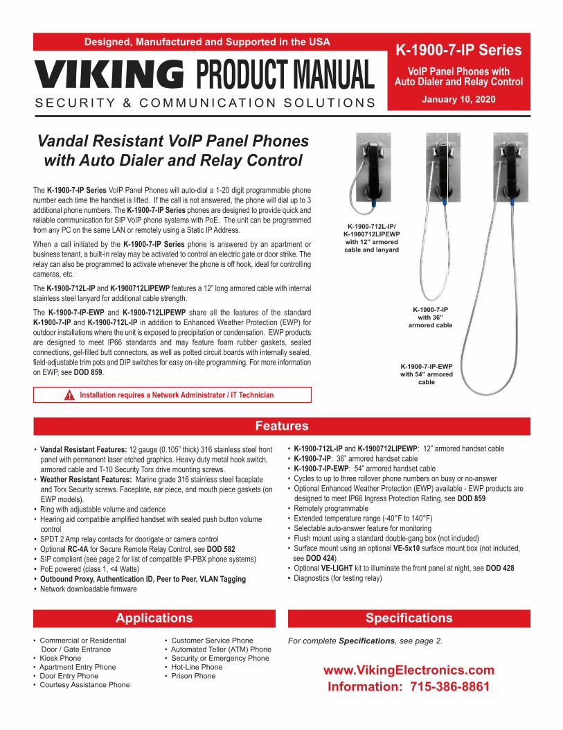
The K-1900-7-IP Series VoIP Panel Phones will auto-dial a 1-20 digit programmable phone
number each time the handset is lifted. If the call is not answered, the phone will dial up to 3
additional phone numbers. The K-1900-7-IP Series phones are designed to provide quick and
reliable communication for SIP VoIP phone systems with PoE. The unit can be programmed
from any PC on the same LAN or remotely using a Static IP Address.
When a call initiated by the K-1900-7-IP Series phone is answered by an apartment or
business tenant, a built-in relay may be activated to control an electric gate or door strike. The
relay can also be programmed to activate whenever the phone is off hook, ideal for controlling
cameras, etc.
The K-1900-712L-IP and K-1900712LIPEWP features a 12” long armored cable with internal
stainless steel lanyard for additional cable strength.
The K-1900-7-IP-EWP and K-1900-712LIPEWP share all the features of the standard
K-1900-7-IP and K-1900-712L-IP in addition to Enhanced Weather Protection (EWP) for
outdoor installations where the unit is exposed to precipitation or condensation. EWP products
are designed to meet IP66 standards and may feature foam rubber gaskets, sealed
connections, gel-filled butt connectors, as well as potted circuit boards with internally sealed,
field-adjustable trim pots and DIP switches for easy on-site programming. For more information
on EWP, see DOD 859.
• Commercial or Residential
Door / Gate Entrance
• Kiosk Phone
• Apartment Entry Phone
• Door Entry Phone
• Courtesy Assistance Phone
• Customer Service Phone
• Automated Teller (ATM) Phone
• Security or Emergency Phone
• Hot-Line Phone
• Prison Phone
K-1900-7-IP Series
VoIP Panel Phones withAuto Dialer and Relay Control
January 10, 2020
Vandal Resistant VoIP Panel Phoneswith Auto Dialer and Relay Control
Features
Installation requires a Network Administrator / IT Technician!
Specifications
www.VikingElectronics.com
Information: 715-386-8861
• Vandal Resistant Features: 12 gauge (0.105” thick) 316 stainless steel front
panel with permanent laser etched graphics. Heavy duty metal hook switch,
armored cable and T-10 Security Torx drive mounting screws.
• Weather Resistant Features: Marine grade 316 stainless steel faceplate
and Torx Security screws. Faceplate, ear piece, and mouth piece gaskets (on
EWP models).
• Ring with adjustable volume and cadence
• Hearing aid compatible amplified handset with sealed push button volume
control
• SPDT 2 Amp relay contacts for door/gate or camera control
• Optional RC-4A for Secure Remote Relay Control, see DOD 582
• SIP compliant (see page 2 for list of compatible IP-PBX phone systems)
• PoE powered (class 1, <4 Watts)
• Outbound Proxy, Authentication ID, Peer to Peer, VLAN Tagging
• Network downloadable firmware
• K-1900-712L-IP and K-1900712LIPEWP: 12” armored handset cable
• K-1900-7-IP: 36” armored handset cable
• K-1900-7-IP-EWP: 54” armored handset cable
• Cycles to up to three rollover phone numbers on busy or no-answer
• Optional Enhanced Weather Protection (EWP) available - EWP products are
designed to meet IP66 Ingress Protection Rating, see DOD 859
• Remotely programmable
• Extended temperature range (-40°F to 140°F)
• Selectable auto-answer feature for monitoring
• Flush mount using a standard double-gang box (not included)
• Surface mount using an optional VE-5x10 surface mount box (not included,
see DOD 424)
• Optional VE-LIGHT kit to illuminate the front panel at night, see DOD 428
• Diagnostics (for testing relay)
For complete Specifications, see page 2.
K-1900-7-IP-EWP
with 54” armored
cable
K-1900-7-IP
with 36”
armored cable
K-1900-712L-IP/
K-1900712LIPEWP
with 12” armored
cable and lanyard
2
VoIP SIP System Compatibility
For compatibility and vendor specific detailed configuration instructions, see the Viking VoIP
SIP System Compatibility List, DOD 944. To open and download this PDF file:
1. Go to www.vikingelectronics.comand enter 944 in the search box
2. Click Application Note (DOD 944)to open and download the PDF
Scan the QR code below to openand download the Viking VoIPSIP System Compatibility List
- OR -
Important: Exclusion from this list means only that compatibility has not been verified, it does not mean
incompatibility. If you have questions, please call Viking Electronics at 715-386-8861.
Power: PoE class 1 (<4 Watts)
Standard Dimensions: 5.0” x 10.0” x 4.97” (127mm x 254mm x 126mm)
EWP Dimensions: 5.0” x 10.0” x 5.1” (127mm x 254mm x 130mm)
Shipping Weight for K-1900-712L-IP/EWP: 3.7 lbs (1.7 kg)
Shipping Weight for K-1900-7-IP/EWP: 3.8 lbs (1.72 kg)
Operating Temperature: -40°F to 140°F (-40° C to 60° C)
Humidity - Standard Products: 5% to 95% non-condensing
Humidity - EWP Products: Up to 100%
Handset Cable Length on K-1900-712L-IP and K-1900712LIPEWP Models: 12” to 12.7” (31 cm to 33 cm)
Handset Cable Length on K-1900-7-IP Model: 34” to 37” (86 cm to 94 cm)
Handset Cable Length on K-1900-7-IP-EWP Model: 52” to 57” (132 cm to 145 cm)
Audio Codecs: G711u, G711a, G722
Network Compliance: IEEE 802.3 af PoE, SIP 2.0 RFC3261, 100BASE-TX with auto cross over
Regulatory Compliance: CE, FCC Part 15 and Canada ICES-003 Class A
Connections: (1) RJ45 10/100 Base-T, (3) gel-filled butt connectors
Specifications

3
Definitions
Client: A computer or device that makes use of a server. As an example, the client might request a particular file from the server.
DHCP: Dynamic Host Configuration Protocol. In this procedure the network server or router takes note of a client’s MAC address and
assigns an IP address to allow the client to communicate with other devices on the network.
DNS Server: A DNS (Domain Name System) server translates domain names (ie: www.vikingelectronics.com) into an IP address.
Ethernet: Ethernet is the most commonly used LAN technology. An Ethernet Local Area Network typically uses twisted pair wires to
achieve transmission speeds up to 1Gbps.
Host: A computer or device connected to a network.
Host Name: A host name is a label assigned to a device connected to a computer network that is used to identify the device in various
forms of network communication.
Hosts File: A file stored in a computer that lists host names and their corresponding IP addresses with the purpose of mapping addresses
to hosts or vice versa.
Internet: A worldwide system of computer networks running on IP protocol which can be accessed by individual computers or networks.
IP: Internet Protocol is the set of communications conventions that govern the way computers communicate on networks and on the
Internet.
IP Address: This is the address that uniquely identifies a host on a network.
LAN: Local Area Network. A LAN is a network connecting computers and other devices within an office or building.
Lease: The amount of time a DHCP server reserves an address it has assigned. If the address isn’t used by the host for a period of
time, the lease can expire and the address can be assigned to another host.
MAC Address: MAC stands for Media Access Control. A MAC address, also called a hardware address or physical address, is a unique
address assigned to a device at the factory. It resides in the device’s memory and is used by routers to send network traffic to the correct
IP address. You can find the MAC address of your K-1900-7-IP Series phone printed on a white label on the top surface of the PoE LAN
port.
Router: A device that forwards data from one network to another. In order to send information to the right location, routers look at IP
Address, MAC Address and Subnet Mask.
RTP: Real-Time Transport Protocol is an Internet protocol standard that specifies a way for programs to manage the real-time transmission
of multimedia data over either unicast or multicast network services.
Server: A computer or device that fulfills requests from a client. This could involve the server sending a particular file requested by the
client.
Session Initiation Protocol (SIP): Is a signaling communications protocol, widely used for controlling multimedia communication sessions
such as voice and video calls over Internet Protocol (IP) networks. The protocol defines the messages that are sent between endpoints,
which govern establishment, termination and other essential elements of a call.
Static IP Address: A static IP Address has been assigned manually and is permanent until it is manually removed. It is not subject to the
Lease limitations of a Dynamic IP Address assigned by the DHCP Server. The default static IP Address is: 192.168.154.1
Subnet: A portion of a network that shares a common address component. On TCP/IP networks, subnets are defined as all devices
whose IP addresses have the same prefix. For example, all devices with IP addresses that start with 100.100.100. would be part of the
same subnet. Dividing a network into subnets is useful for both security and performance reasons. IP networks are divided using a subnet
mask.
TCP/IP: Transmission Control Protocol/Internet Protocol is the suite of communications protocols used to connect hosts on the Internet.
TCP/IP uses several protocols, the two main ones being TCP and IP. TCP/IP is built into the UNIX operating system and is used by the
Internet, making it the de facto standard for transmitting data over networks.
TISP: Telephone Internet Service Provider
WAN: Wide Area Network. A WAN is a network comprising a large geographical area like a state or country. The largest WAN is the
Internet.
Wireless Access Point (AP): A device that allows wireless devices to connect to a wired network using Wi-Fi, or related standards. The
AP usually connects to a router (via a wired network) as a standalone device, but it can also be an integral component of the router itself.
Wireless Repeater (Wireless Range Extender): takes an existing signal from a wireless router or access point and rebroadcasts it to
create a second network. When two or more hosts have to be connected with one another over the IEEE 802.11 protocol and the distance
is too long for a direct connection to be established, a wireless repeater is used to bridge the gap.
4
Features Overview
MA
C:
18E
80F
XX
XX
XX
asdesa
xtff
N.C. (Gray)
N.O. (Yellow)
COM. (Blue)
Relay 1Output Contacts
(2A@30VDC/ 250VAC max)
* 3 Gel-Filled Butt
Connectors (included)
Yellow
Yellow
Black
Black
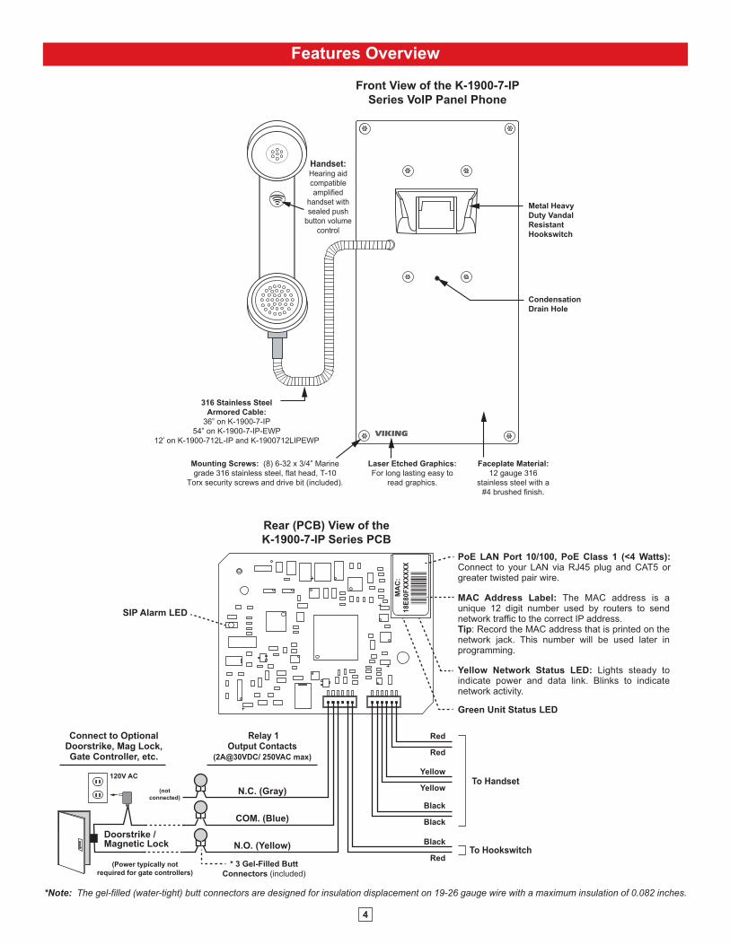
MAC Address Label: The MAC address is a unique 12 digit number used by routers to send network traffic to the correct IP address. Tip: Record the MAC address that is printed on the network jack. This number will be used later in programming.
PoE LAN Port 10/100, PoE Class 1 (<4 Watts): Connect to your LAN via RJ45 plug and CAT5 or greater twisted pair wire.
Yellow Network Status LED: Lights steady to indicate power and data link. Blinks to indicate network activity.
Green Unit Status LED
Rear (PCB) View of the
K-1900-7-IP Series PCB
Red
Red
(Power typically not
required for gate controllers)
Doorstrike / Magnetic Lock
120V AC
Connect to Optional Doorstrike, Mag Lock, Gate Controller, etc.
(not
connected)
Black
Red
SIP Alarm LED
To Handset
To Hookswitch
*Note: The gel-filled (water-tight) butt connectors are designed for insulation displacement on 19-26 gauge wire with a maximum insulation of 0.082 inches.
Front View of the K-1900-7-IP
Series VoIP Panel Phone
Condensation
Drain Hole
Mounting Screws: (8) 6-32 x 3/4” Marine
grade 316 stainless steel, flat head, T-10
Torx security screws and drive bit (included).
Laser Etched Graphics:
For long lasting easy to
read graphics.
Faceplate Material:
12 gauge 316
stainless steel with a
#4 brushed finish.
Metal Heavy
Duty Vandal
Resistant
Hookswitch
316 Stainless Steel
Armored Cable:
36” on K-1900-7-IP
54” on K-1900-7-IP-EWP
12’ on K-1900-712L-IP and K-1900712LIPEWP
VIKING
Handset:Hearing aid
compatible
amplified
handset with
sealed push
button volume
control

5
Installation and Mounting
Side View
of the K-1900-7-IP
(8) #6-32 x 3/4" Stainless
Steel T-10 Torx Security
Screws (included)
10.0"
9.5"
4.50"
5.00"
3.28"
1.55"
Front View
of the K-1900-7-IP
1.8"
2.75"
2.1"3.5"
Double Gang Box
(not included)
Viking’s optional Surface Mount Boxes
(VE-5x10 shown right) are designed to be
surface mounted to a single gang box,
double gang box, or any Viking Gooseneck
Pedestal (VE-GNP shown left). For more
information on Viking Surface Mount Boxes
or Gooseneck Pedestals, see DOD 424.
K-1900-7-IP-EWP shown
with VE-5x10 Surface
Mount Box and VE-GNP
Gooseneck Pedestal
(not included)
Earth Ground the Green/Yellow wire using the
provided wire nut Earth
GroundOR
Optional Surface Mount Box,
model VE-5x10 shown
(not included) other models
also available
10.14"
3.69"5.22"
To install the K-1900-7-IP Series panel phone, attach the panel to a standard double gang electrical box using the provided
screws or use the optional VE-5x10 or VE-5X10-SS weather resistant surface mount box. Note: Four extra screws and
nuts are provided to fill the unused mounting holes. The optional VE-5x10 surface mount box (shown below) is designed to
be surface mounted to a wall, post, single gang box or a VE-GNP or VE-GNP-2 goose neck pedestal. The K-1900-7-IP
Series can also be mounted in an optional VE-9x20 Weatherproof Enclosure (DOD 413).
Note: When mounting a K-1900-7-IP-EWP in a VE-9x20, the length of the handset cable must be reduced. Use a 3/32”
hex key or bit to loosen the set screw in the brass handset cable retainer. Pull approximately 18 inches of the cable through
the panel and retighten the set screw.
Tip: Record the MAC address that is printed on the network jack. This number will be used later in programming.
IMPORTANT: Electronic devices are susceptible to lightning and power station electrical surges from both the ACoutlet and the telephone line. It is recommended that a surge protector be installed to protect against such surges.
6
PC Requirements
PC Programming
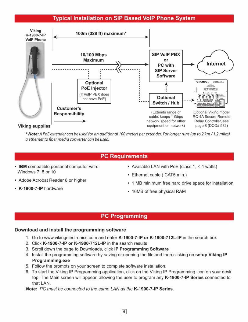
Typical Installation on SIP Based VoIP Phone System
SIP VoIP PBX
or
PC with
SIP Server
Software
100m (328 ft) maximum*
Viking supplies
Customer’s
Responsibility
Internet
10/100 Mbps
Maximum
Viking
K-1900-7-IP
VoIP Phone
* Note: A PoE extender can be used for an additional 100 meters per extender. For longer runs (up to 2 km / 1.2 miles)
a ethernet to fiber media converter can be used.
Optional
PoE Injector
(If VoIP PBX does
not have PoE) Optional
Switch / Hub
(Extends range of
cable, keeps 1 Gbps
network speed for other
equipment on network)
LED 7LED 5 LED 8LED 6
LED 3LED 2LED 1
LED 9
LED 4
1 2 3
on
4
MA
C:
18E
80F
XX
XX
XX
asdesaxtff
C NO NCRL 1
C NO NCRL 2
C NO NCRL 3
C NO NCRL 4 1 2 3 4 NETWORK
1 2 3 4 NETWORK
VIKING
ELECTRONICS
HUDSON, WI 54016
NETWORK ENABLED
RELAY CONTROLLER
MODEL RC-4A©VIKING
1
IN1 C IN2 IN3 C IN4
2 3 4 5 6
LOGIC LEVEL
PROGRAMMING
RESTORE DEFAULTS
DEBOUNCE
PO
WE
R 1
2V
DC
RELAY 1 RELAY 2 RELAY 3 RELAY 4
1 2 3 4 5 7 8 9 10 11 126
STATUS
LED
Optional Viking model
RC-4A Secure Remote
Relay Controller, see
page 8 (DOD# 582)
• IBM compatible personal computer with:
Windows 7, 8 or 10
• Adobe Acrobat Reader 8 or higher
• K-1900-7-IP hardware
• Available LAN with PoE (class 1, < 4 watts)
• Ethernet cable ( CAT5 min.)
• 1 MB minimum free hard drive space for installation
• 16MB of free physical RAM
Download and install the programming software
1. Go to www.vikingelectronics.com and enter K-1900-7-IP or K-1900-712L-IP in the search box
2. Click K-1900-7-IP or K-1900-712L-IP in the search results
3. Scroll down the page to Downloads, click IP Programming Software
4. Install the programming software by saving or opening the file and then clicking on setup Viking IP
Programming.exe
5. Follow the prompts on your screen to complete software installation.
6. To start the Viking IP Programming application, click on the Viking IP Programming icon on your desk
top. The Main screen will appear, allowing the user to program any K-1900-7-IP Series connected to
that LAN.
Note: PC must be connected to the same LAN as the K-1900-7-IP Series.
7
A. Manually Muting SIP/Network Failure Alarm Beeps (3 beeps repeated every 3 seconds)
With the unit connected and powered (Green LED on and Yellow LED off or blinking) it will output 3 beeps every 3
seconds in the handset of the K-1900-7-IP Series phone indicating a SIP registration failure, failure to receive an echo
reply from a pinged gateway or Ethernet connection failure. You can manually disable the beeps by clicking the “Mute
Alarm Until Next Failure” tab in the Viking IP programming software. The LED will continue to flash allowing you to
trouble shoot the failure.
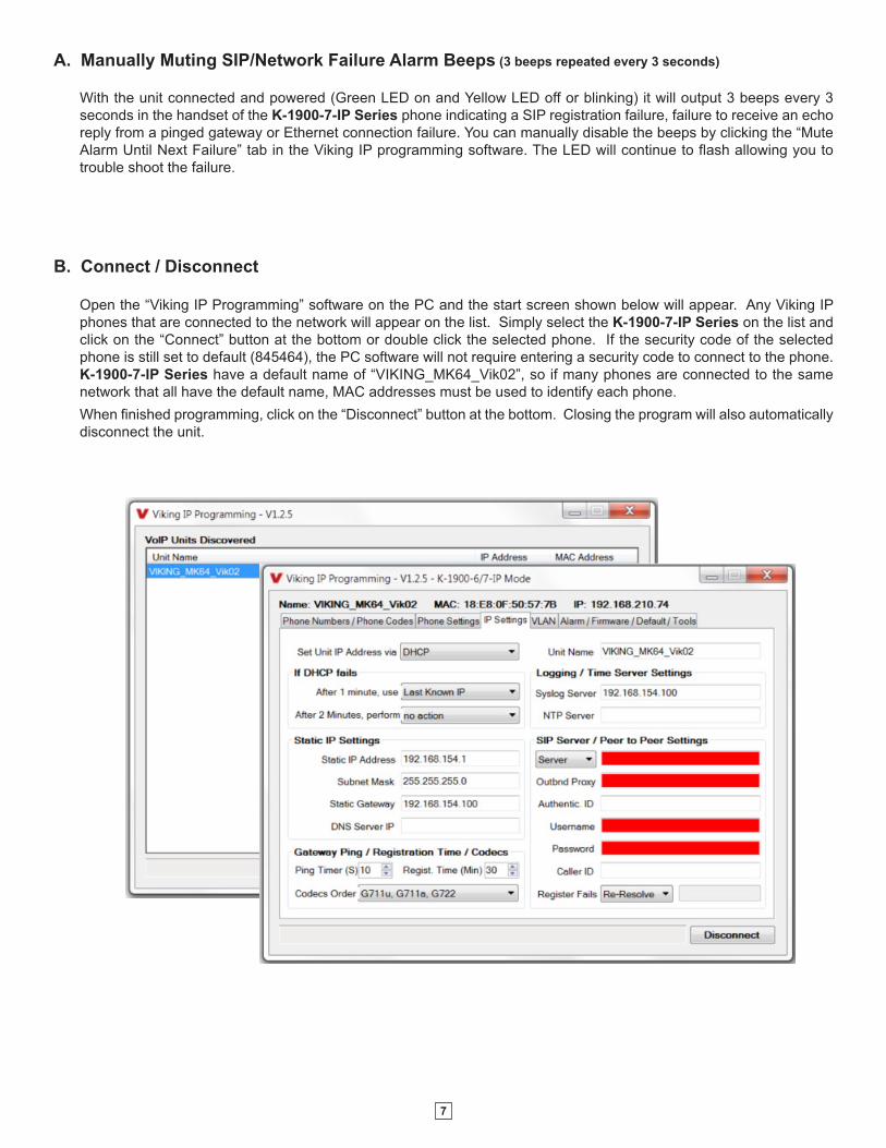
B. Connect / Disconnect
Open the “Viking IP Programming” software on the PC and the start screen shown below will appear. Any Viking IP
phones that are connected to the network will appear on the list. Simply select the K-1900-7-IP Series on the list and
click on the “Connect” button at the bottom or double click the selected phone. If the security code of the selected
phone is still set to default (845464), the PC software will not require entering a security code to connect to the phone.
K-1900-7-IP Series have a default name of “VIKING_MK64_Vik02”, so if many phones are connected to the same
network that all have the default name, MAC addresses must be used to identify each phone.
When finished programming, click on the “Disconnect” button at the bottom. Closing the program will also automatically
disconnect the unit.
8
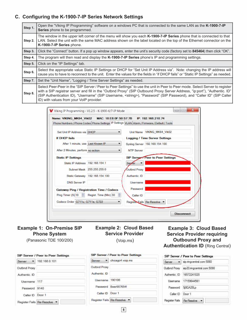
C. Configuring the K-1900-7-IP Series Network Settings
Step 1.Open the “Viking IP Programming” software on a windows PC that is connected to the same LAN as the K-1900-7-IP
Series phone to be programmed.
Step 2.
The window in the upper left corner of the menu will show you each K-1900-7-IP Series phone that is connected to that
LAN. Select the unit with the same MAC address shown on the label located on the top of the Ethernet connector on the
K-1900-7-IP Series phone.
Step 3. Click the “Connect” button. If a pop up window appears, enter the unit’s security code (factory set to 845464) then click “OK”.
Step 4. The program will then read and display the K-1900-7-IP Series phone’s IP and programming settings.
Step 5. Click on the “IP Settings” tab.
Step 6.Select the appropriate value Static IP Settings or DHCP for “Set Unit IP Address via”. Note: changing the IP address will
cause you to have to reconnect to the unit. Enter the values for the fields in “if DHCP fails” or “Static IP Settings” as needed.
Step 7. Set the “Unit Name”, “Logging / Time Server Settings” as needed.
Step 8.
Select Peer-Peer in the “SIP Server / Peer to Peer Settings” to use the unit in Peer to Peer mode. Select Server to register
with a SIP registrar server and fill in the “Outbnd Proxy” (SIP Outbound Proxy Server Address, “ip:port”), “Authentic. ID”
(SIP Authentication ID), “Username” (SIP Username, <string>), “Password” (SIP Password), and “Caller ID” (SIP Caller
ID) with values from your VoIP provider.
Example 2: Cloud Based
Service Provider
(Voip.ms)
Example 3: Cloud Based
Service Provider requiring
Outbound Proxy and
Authentication ID (Ring Central)
Example 1: On-Premise SIP
Phone System
(Panasonic TDE 100/200)
9
Step 1. Power down the K-1900-7-IP Series phone by disconnecting the LAN Cable (RJ45 plug).
Step 2. Take the handset offhook, then reconnect the LAN Cable (RJ45 plug).
Step 3.8-12 seconds after connecting the LAN Cable you should hear 2 beeps in the handset. Go back on-hook within 6 seconds and you
should hear 2 more beeps.
Step 4. The security code is now reset to 845464 (factory default).
Step 5. You can now enter programming by following the steps in section B above.
E. Manually Resetting the Security Code to Enter Programming
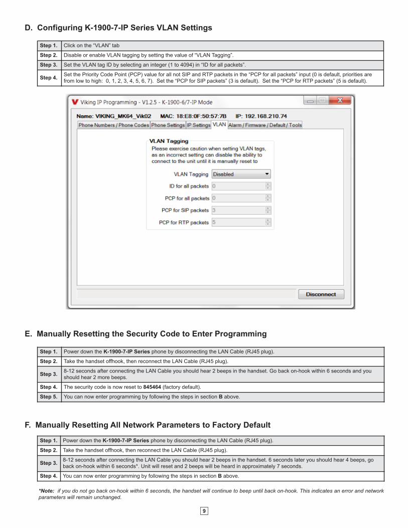
Step 1. Click on the “VLAN” tab
Step 2. Disable or enable VLAN tagging by setting the value of “VLAN Tagging”.
Step 3. Set the VLAN tag ID by selecting an integer (1 to 4094) in “ID for all packets”.
Step 4.Set the Priority Code Point (PCP) value for all not SIP and RTP packets in the “PCP for all packets” input (0 is default, priorities are
from low to high: 0, 1, 2, 3, 4, 5, 6, 7). Set the “PCP for SIP packets” (3 is default). Set the “PCP for RTP packets” (5 is default).
D. Configuring K-1900-7-IP Series VLAN Settings
F. Manually Resetting All Network Parameters to Factory Default
Step 1. Power down the K-1900-7-IP Series phone by disconnecting the LAN Cable (RJ45 plug).
Step 2. Take the handset offhook, then reconnect the LAN Cable (RJ45 plug).
Step 3.8-12 seconds after connecting the LAN Cable you should hear 2 beeps in the handset. 6 seconds later you should hear 4 beeps, go
back on-hook within 6 seconds*. Unit will reset and 2 beeps will be heard in approximately 7 seconds.
Step 4. You can now enter programming by following the steps in section B above.
*Note: if you do not go back on-hook within 6 seconds, the handset will continue to beep until back on-hook. This indicates an error and network
parameters will remain unchanged.
10
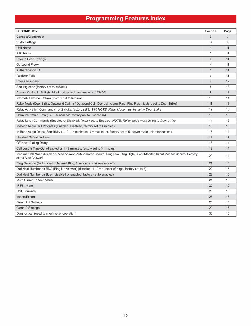
Programming Features Index
DESCRIPTION Section Page
Connect/Disconnect B 7
VLAN Settings D 9
Unit Name 1 11
SIP Server 2 11
Peer to Peer Settings 3 11
Outbound Proxy 4 11
Authentication ID 5 11
Register Fails 6 11
Phone Numbers 7 12
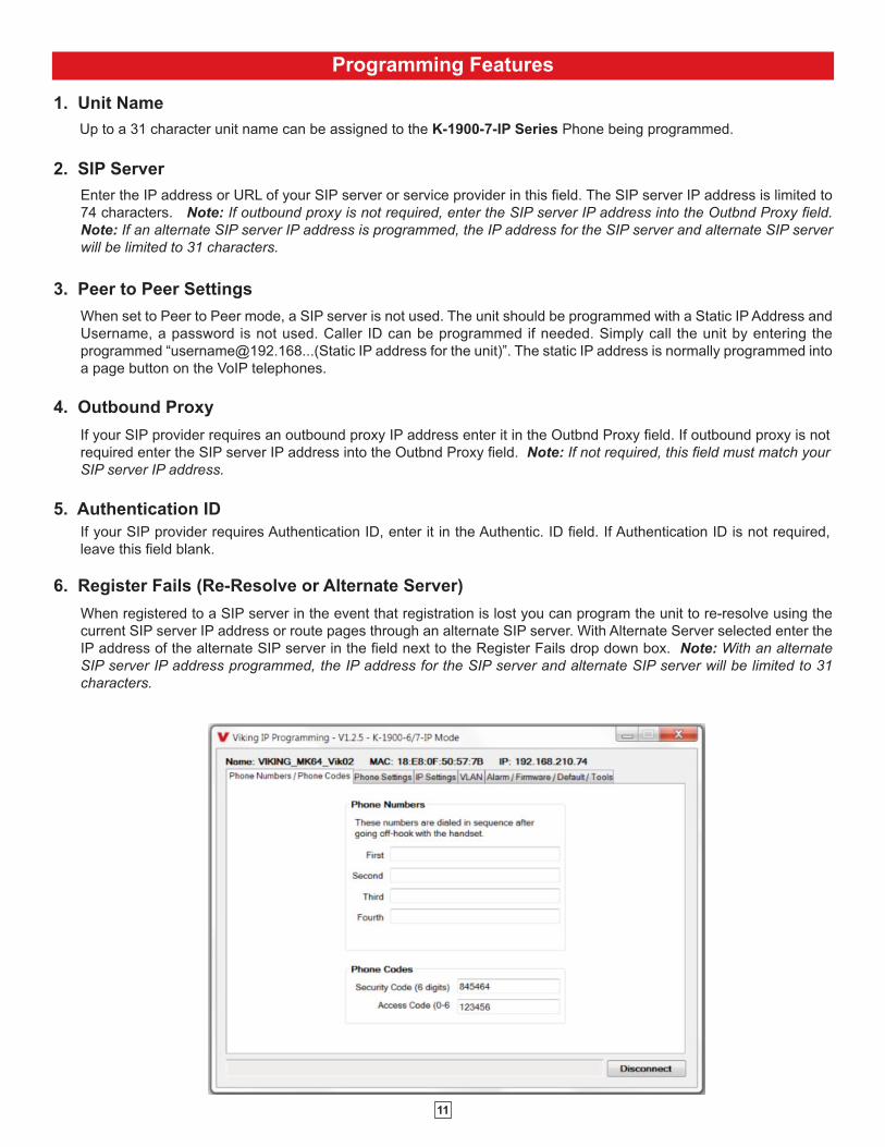
Security code (factory set to 845464) 8 13
Access Code (1 - 6 digits, blank = disabled, factory set to 123456) 9 13
Internal / External Relays (factory set to Internal) 10 14
Relay Mode (Door Strike, Outbound Call, In / Outbound Call, Doorbell, Alarm, Ring, Ring Flash, factory set to Door Strike) 11 13
Relay Activation Command (1 or 2 digits, factory set to QQ) NOTE: Relay Mode must be set to Door Strike 12 13
Relay Activation Time (0.5 - 99 seconds, factory set to 5 seconds) 13 13
Relay Latch Commands (Enabled or Disabled, factory set to Enabled) NOTE: Relay Mode must be set to Door Strike 14 13
In-Band Audio Call Progress (Enabled, Disabled, factory set to Enabled) 15 13
In-Band Audio Detect Sensitivity (1 - 9, 1 = minimum, 9 = maximum, factory set to 5, power cycle unit after setting) 16 14
Handset Default Volume 17 14
Off Hook Dialing Delay 18 14
Call Length Time Out (disabled or 1 - 9 minutes, factory set to 3 minutes) 19 14
Inbound Call Mode (Disabled, Auto Answer, Auto Answer-Secure, Ring Low, Ring High, Silent Monitor, Silent Monitor Secure, Factory
set to Auto Answer)20 14
Ring Cadence (factorty set to Normal Ring, 2 seconds on 4 seconds off) 21 15
Dial Next Number on RNA (Ring No Answer) (disabled, 1 - 9 = number of rings, factory set to 7) 22 15
Dial Next Number on Busy (disabled or enabled, factory set to enabled) 23 15
Mute Current / Next Alarm 24 15
IP Firmware 25 16
Unit Firmware 26 16
Import/Export 27 16
Clear Unit Settings 28 16
Clear IP Settings 29 16
Diagnostics (used to check relay operation) 30 16
11
Programming Features
3. Peer to Peer Settings
When set to Peer to Peer mode, a SIP server is not used. The unit should be programmed with a Static IP Address and
Username, a password is not used. Caller ID can be programmed if needed. Simply call the unit by entering the
programmed “[email protected]...(Static IP address for the unit)”. The static IP address is normally programmed into
a page button on the VoIP telephones.
When registered to a SIP server in the event that registration is lost you can program the unit to re-resolve using the
current SIP server IP address or route pages through an alternate SIP server. With Alternate Server selected enter the
IP address of the alternate SIP server in the field next to the Register Fails drop down box. Note: With an alternate
SIP server IP address programmed, the IP address for the SIP server and alternate SIP server will be limited to 31
characters.
6. Register Fails (Re-Resolve or Alternate Server)
4. Outbound Proxy
If your SIP provider requires an outbound proxy IP address enter it in the Outbnd Proxy field. If outbound proxy is not
required enter the SIP server IP address into the Outbnd Proxy field. Note: If not required, this field must match your
SIP server IP address.
5. Authentication ID
If your SIP provider requires Authentication ID, enter it in the Authentic. ID field. If Authentication ID is not required,
leave this field blank.
Enter the IP address or URL of your SIP server or service provider in this field. The SIP server IP address is limited to
74 characters. Note: If outbound proxy is not required, enter the SIP server IP address into the Outbnd Proxy field.
Note: If an alternate SIP server IP address is programmed, the IP address for the SIP server and alternate SIP server
will be limited to 31 characters.
2. SIP Server
1. Unit Name
Up to a 31 character unit name can be assigned to the K-1900-7-IP Series Phone being programmed.
12
The security code allows the user/installer to program the K-1900-7-IP Series phone. It is recommended that the factory
set security code be changed. Factory Setting: 845464
Note: The security code must be 6 digits and cannot include a Q or a #.
8. Security Code
The access code comes into play when a tenant calls the K-1900-7-IP Series phone and a visitor lifts the handset to
answer the call or the K-1900-7-IP Series phone automatically answers the call (see Inbound Call Mode). It is a 1 - 6
digit code (can not contain “Q” or “#”) that the tenant must dial before they are allowed to operate the door strike relays,as extra security on inbound calls. Once a tenant has entered the correct access code, 2 beeps are heard and the user
can now enter any “Remote Access Operation Commands” (see page 17). This code is also used to enable audio in
Auto Answer Secure and Silent Monitor Secure modes. The access code can be disabled if this basic security is not
required. Factory Setting: 123456
9. Access Code
The phone number programmed in the first location is the number that is dialed when the K-1900-7-IP Series phone
goes off hook. Additional numbers will be dialed when there is no answer or a busy signal is detected. The K-1900-7-
IP Series phone is factory set with no phone numbers programmed. These phone numbers can be up to 20 digits.
7. Phone Numbers (1 - 4)
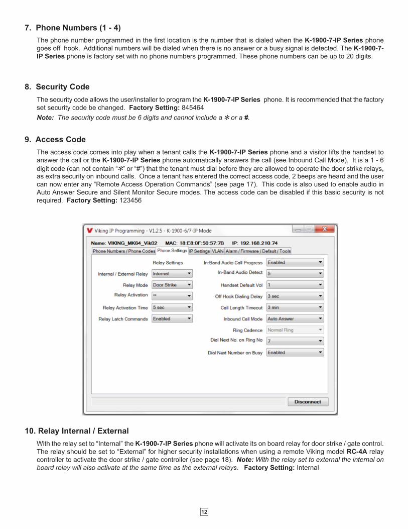
With the relay set to “Internal” the K-1900-7-IP Series phone will activate its on board relay for door strike / gate control.
The relay should be set to “External” for higher security installations when using a remote Viking model RC-4A relay
controller to activate the door strike / gate controller (see page 18). Note: With the relay set to external the internal on
board relay will also activate at the same time as the external relays. Factory Setting: Internal
10. Relay Internal / External
13
The one or two digit code stored in the Relay Activation Command is the touch tone command that the person being
called must enter on their phone in order to momentarily activate the relay to control a doorstrike, mag-lock, gate
controller, or other device. The code can contain up to two of the following characters 0 - 9, # or Q. The code cannotmatch a relay latching or toggle command (11, 10, 1#) unless latching commands are disabled. The code must be
entered while the remote phone is communicating with the Entry phone. The Entry phone determines which direction
the touch tone is coming from and only responds to touch tones from the called phone. Factory Setting QQ.
12. Relay Activation Command
The value stored in the Relay Activation Time is the amount of time the relay will be energized after a correct momentary
touch tone command is entered. This number can range from 0.5 - 99 seconds. Note: This also affects timing in
Doorbell Mode. Factory Setting: 5 seconds
13. Relay Activation Time
Doorstrike Mode (Factory Setting): When programmed for Doorstrike Mode the relay is intended for door strike,
maglock or gate control. The relay will momentarily activate for the preprogrammed relay activation time after detecting
the correct relay activation command (one or two digit touch tone) from the called party.
Outbound Call Mode: When programmed for Outbound Call Mode the relay will activate continuously for the duration
of any outbound call from the Entry phone.
Inbound/Outbound Call Mode: When programmed for Inbound/Outbound Call Mode the relay will activate
continuously for the duration of any inbound or outbound call to or from the Entry phone. This mode is useful for turning
on IR flood lights, for VoIP phones with cameras, etc.
Doorbell Mode: When programmed for Doorbell Mode the relay will momentarily activate the relay for the
preprogrammed relay activation time on any outbound call from the Entry phone. This mode is useful for activating a
door chime, etc. When activating door chimes, a 0.5 - 1 second relay activation time is recommended.
Alarm Mode: When programmed in Alarm Mode the relay will activate continuously while the Entry phone is powered
and registered to the SIP server. In the event the unit loses power and/or SIP registration the relay will turn off, which
can be used to signal an alarm device. This can only be used for internal relay control.
Ring Mode: When programmed for Ring Mode the relay will continuously activate when an inbound call is ringing to
the entry phone. This mode is useful for activating a Viking model SL-2 strobe light, etc.
Note: Inbound Call Mode must be set to Ring Low or Ring High.
Ring Flash Mode: When programmed for Ring Flash Mode the relay will momentarily turn on and off in a 400ms
on/off cadence when an inbound call is ringing to the entry phone. This mode is useful for activating a Viking LPL-1
Remote Visual Indicator, etc.
Note: Inbound Call Mode must be set to Ring Low or Ring High.
11. Relay Mode
14. Relay Latch Commands
When set to “Enabled” the Remote Access Operation Commands to Un-Latch, Latch or Toggle the relay are enabled.
When set to “Disable” the Remote Access Operation Commands to Un-Latch, Latch or Toggle the relay are disabled.
Disabling the Latch commands can be useful in applications where you want to eliminate the possibility of inadvertently
entering a latch command leaving a gate open/closed, etc. The relays can still be activated with the “Relay Activation
Command” for momentary closures. Factory Setting: Enabled
The In-Band Audio Call Progress Detection can be set to Enabled or Disabled. In-Band Audio Call Progress detection
should be enabled in applications where you are making an outbound call through your VoIP phone system and are
relying on In-Band analog audio for ringback or busy detection. Factory Setting: Enabled.
15. In-Band Audio Call Progress
14
18. Off Hook Dialing Delay
17. Handset Default Volume
The Off Hook Dialing Delay is the length of time a user hears simulated dial tone after picking up the handset before
the first number is dialed. The Off Hook Dialing Delay can be set to 1 - 6 seconds or “No Delay”.
Factory Setting: 3 seconds
The In-Band Audio Detect level (Sensitivity) can be set from 1 - 9, 1 = minimum setting, 9 = highest setting. Increasing
or decreasing the sensitivity may be required in applications where you are making an outbound call through your VoIP
phone system and are relying on In-Band analog audio detection. Power cycle unit after changing this setting.
Factory Setting: 5
16. In-Band Audio Detection Sensitivity
This feature selects the maximum length of time that calls can be connected. Programmable in increments of 1 minute
up to a maximum of 9 minutes or disabled. With the call length disabled, the K-1900-7-IP Series phone must rely on
a call ended signal, busy signal, or touch tone # to hang-up. Factory Setting: 3 minutes
Note: Timer starts after call is connected. If call is not answered (and ring no answer disabled) there is a default 7
minute timer.
19. Call Length Time Out
The Handset Default Volume can be set from 1 - 4, 1 = lowest volume setting, 4 = highest volume setting. This will be
the default volume setting from off hook but then can be increased or decreased with the handset volume control button.
Setting it to “1, 2, 3, or 4 only” will lock the volume at that setting for all calls (handset volume control button disabled).
Setting it to “last used” will leave the handset volume set to the last user adjusted volume setting. Factory Setting: 1
The Inbound Call Mode determines how the K-1900-7-IP Series phone handles incoming calls. One option is to
generate a ring sound through the handset receiver, allowing someone to lift the handset to answer the inbound SIP
call. The K-1900-7-IP Series phone can also auto answer the call, to allow remote control of the doorstrike relay and
the ability to listen to transmit audio from the handset of the phone. The last option is the silent monitor mode, which
allows callers to listen to the transmit audio from the handset of the phone at a much higher volume than normal. The
“secure” options for auto answer and silent monitor require the callers to dial the access code in order to remain
connected and listen to the audio from the handset. Factory Setting: Auto Answer
Disabled – Inbound calls are not allowed.
Auto Answer – Inbound calls are auto answered and the caller hears transmit audio from the handset at a normal
volume level.
Auto Answer Secure – Inbound calls are auto answered and the caller must dial the access code in order to listen to
transmit audio from the handset (volume level is still normal).
Ring Low – In the “low” mode the phone will output a ring signal out of the earpiece in the ring pattern selected in
Ring Cadence. The call can then be answered by taking the handset off hook.
Ring High – In the “High” mode the phone will output a slightly louder, higher pitched ring signal out of the earpiece
in the ring pattern selected in Ring Cadence. The call can then be answered by taking the handset off hook.
Silent Monitor – Inbound calls are auto answered and the caller hears transmit audio from the handset at a much
higher volume level.
Silent Monitor Secure – Inbound calls are auto answered and the caller must dial the access code in order to listen
to transmit audio from the handset (volume level is still at a much higher volume level).
20. Inbound Call Mode
15
If enabled and a ring-no-answer is detected, the K-1900-7-IP Series phone will dial the other phone numbers.
Factory Setting: 7 (will redial after 7 rings)
When “Inbound Call Mode” on the K-1900-7-IP Series phone is set to “Ring Low” or “Ring High,” the Ring cadence
can be programmed to one of 4 different cadences: Factory Setting: Normal Ring
Normal Ring (single ring, 2 seconds on 4 seconds off)
Double Ring (double ring, 1 second on 0.5 seconds off 1 second on 3.5 seconds off)
Short-Short-Long (triple ring, 0.5 seconds on 0.5 seconds off 0.5 seconds on 0.5 seconds off 1 second on 3 seconds off)
Short-Long-Short (triple ring, 0.5 seconds on 0.5 seconds off 1 second on 0.5 seconds off 0.5 seconds on 3 seconds off)
21. Ring Cadence
If enabled and a busy is detected, the K-1900-7-IP Series phone will dial the other phone numbers.
Notes: If the busy signal is interrupted with a promotional message, contact your central office to have it removed.
23. Dial Next Number on Busy
22. Dial Next Number on Ring No Answer
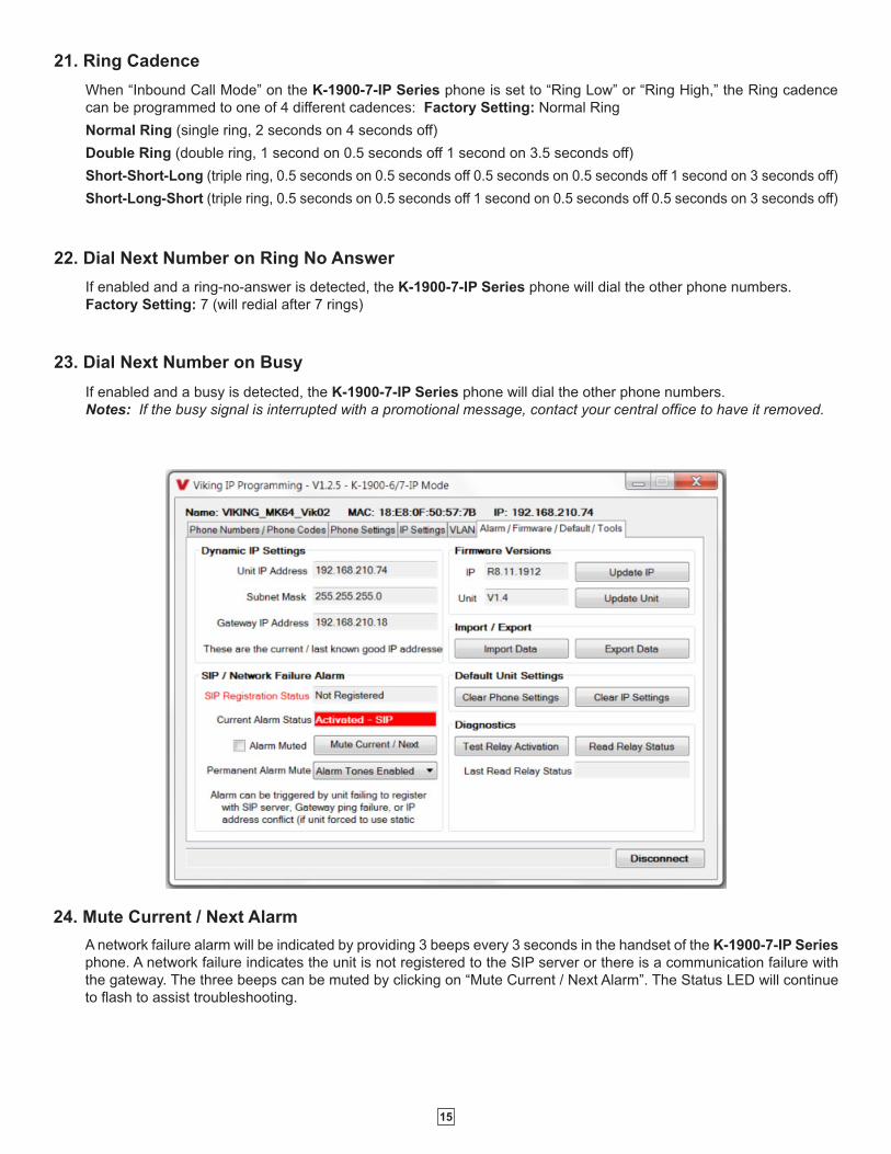
24. Mute Current / Next Alarm
A network failure alarm will be indicated by providing 3 beeps every 3 seconds in the handset of the K-1900-7-IP Series
phone. A network failure indicates the unit is not registered to the SIP server or there is a communication failure with
the gateway. The three beeps can be muted by clicking on “Mute Current / Next Alarm”. The Status LED will continue
to flash to assist troubleshooting.
16
25. IP Firmware
If new K-1900-7-IP Series firmware is available, after opening the programming software a pop window will come up
asking you if you would like to update firmware. An alternative method of updating can be done by clicking the IP
firmware “Update IP” button. You can then browse to the folder that contains the PIP file for updating the unit’s IP
firmware. This method is typically only used when Viking Technical Support has sent you updated IP firmware.
The Import/Export feature is useful for backing up all the K-1900-7-IP Series programming or for importing programming
when installing multiple units with a majority of the same programming.
26. Unit Firmware
If new K-1900-7-IP Series firmware is available, after opening the programming software a pop window will come up
asking you if you would like to update firmware. An alternative method of updating can be done by clicking the Unit
firmware “Update Unit” button. You can then browse to the folder that contains the HEX file for updating the unit’s
firmware. This method is typically only used when Viking Technical Support has sent you updated firmware.
Note: Export your phone settings before updating firmware.
27. Import/Export
Clicking on the “Clear Phone Settings” button in programming will reset all of the Phone Settings back to their factory
default settings. Note: This command will not change or reset your IP settings or erase any programmed phone
numbers.
28. Clear Phone Settings
30. Diagnostics
Clicking on the “Clear IP Settings” will reset the unit’s name, IP and SIP settings back to their factory default settings.
Note: This will not effect any unit / phone settings or erase any programmed phone numbers.
29. Clear IP Settings
The Diagnostics section in the Viking IP Programming can be used to test the functionality of the relay and read current
relay status.
17
Operation
A. Making a Call
When the handset is taken off-hook, the K-1900-7-IP Series dials the pre-programmed telephone number stored in the first phone
number location. In the event the line is busy or there is a ring-no-answer, the unit can be programmed to call up to 4 additional roll
over numbers.
When the call is answered, relay activation commands can be entered or the # key can be used to force the phone to hang-up.
After communication is established, enter the 1 or 2 digit relay activation command (factory set to “QQ”) to momentarily activate theentry phone (door strike) relay. Two beeps will be heard confirming that the relay has been activated. If you require the relay to
remain on continuously (ie: a truck delivery), enter Touch Tones “11” to continuously activate the relay. A double beep will indicate
that the relay is latched on. When the visitor calls in again (ie: they are finished unloading the truck), enter Touch Tones “10” to
deactivate the relay. A single beep will indicate the relay is latched off.
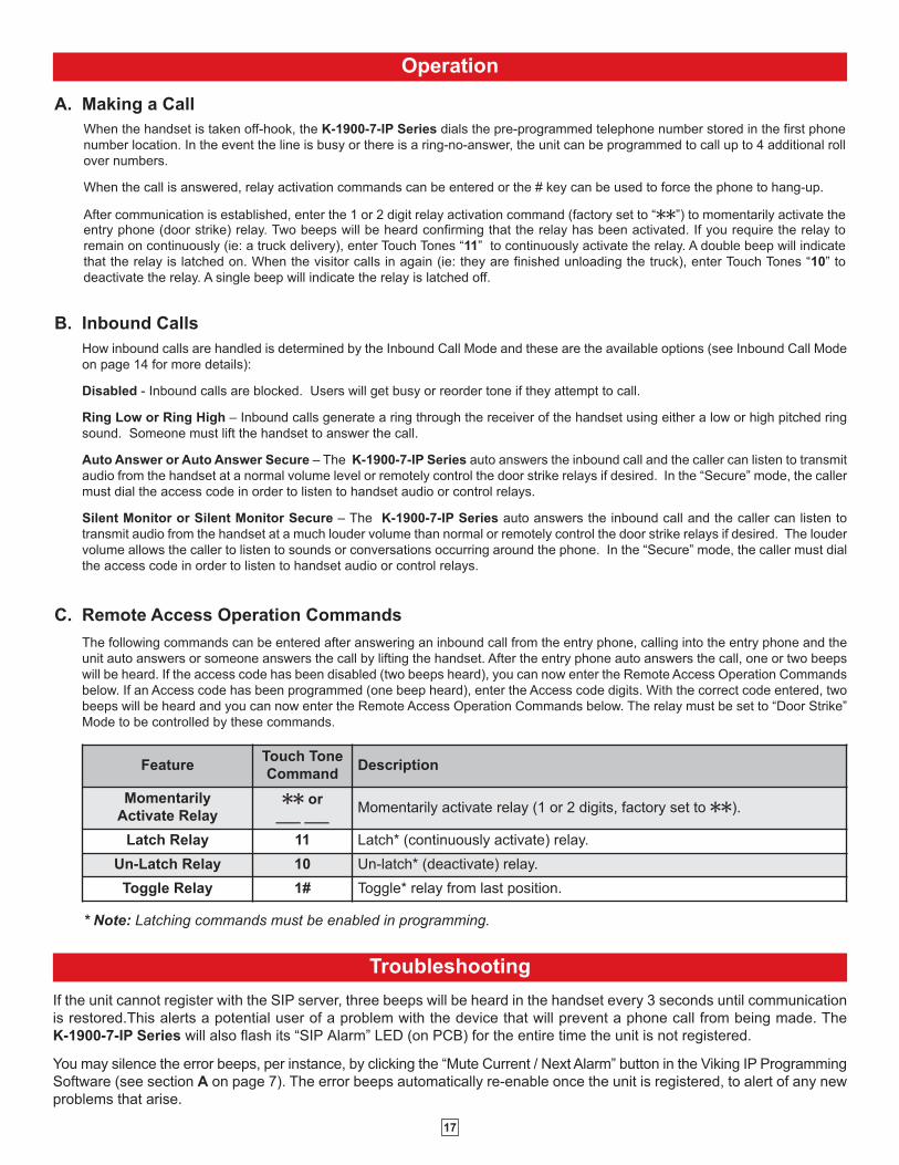
FeatureTouch Tone
CommandDescription
Momentarily
Activate Relay QQ or
___ ___Momentarily activate relay (1 or 2 digits, factory set to QQ).
Latch Relay 11 Latch* (continuously activate) relay.
Un-Latch Relay 10 Un-latch* (deactivate) relay.
Toggle Relay 1# Toggle* relay from last position.
C. Remote Access Operation Commands
The following commands can be entered after answering an inbound call from the entry phone, calling into the entry phone and the
unit auto answers or someone answers the call by lifting the handset. After the entry phone auto answers the call, one or two beeps
will be heard. If the access code has been disabled (two beeps heard), you can now enter the Remote Access Operation Commands
below. If an Access code has been programmed (one beep heard), enter the Access code digits. With the correct code entered, two
beeps will be heard and you can now enter the Remote Access Operation Commands below. The relay must be set to “Door Strike”
Mode to be controlled by these commands.
* Note: Latching commands must be enabled in programming.
Troubleshooting
If the unit cannot register with the SIP server, three beeps will be heard in the handset every 3 seconds until communication
is restored.This alerts a potential user of a problem with the device that will prevent a phone call from being made. The
K-1900-7-IP Series will also flash its “SIP Alarm” LED (on PCB) for the entire time the unit is not registered.
You may silence the error beeps, per instance, by clicking the “Mute Current / Next Alarm” button in the Viking IP Programming
Software (see section A on page 7). The error beeps automatically re-enable once the unit is registered, to alert of any new
problems that arise.
B. Inbound Calls
How inbound calls are handled is determined by the Inbound Call Mode and these are the available options (see Inbound Call Mode
on page 14 for more details):
Disabled - Inbound calls are blocked. Users will get busy or reorder tone if they attempt to call.
Ring Low or Ring High – Inbound calls generate a ring through the receiver of the handset using either a low or high pitched ring
sound. Someone must lift the handset to answer the call.
Auto Answer or Auto Answer Secure – The K-1900-7-IP Series auto answers the inbound call and the caller can listen to transmit
audio from the handset at a normal volume level or remotely control the door strike relays if desired. In the “Secure” mode, the caller
must dial the access code in order to listen to handset audio or control relays.
Silent Monitor or Silent Monitor Secure – The K-1900-7-IP Series auto answers the inbound call and the caller can listen to
transmit audio from the handset at a much louder volume than normal or remotely control the door strike relays if desired. The louder
volume allows the caller to listen to sounds or conversations occurring around the phone. In the “Secure” mode, the caller must dial
the access code in order to listen to handset audio or control relays.
18
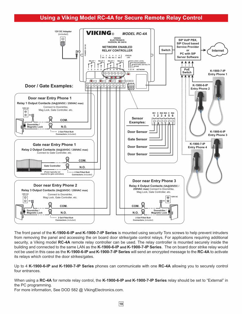
Using a Viking Model RC-4A for Secure Remote Relay Control
Switch
SIP VoIP PBX,
SIP Cloud based
Service Provider
or
PC with SIP
Server Software
Internet
PoESwitch
LED 8LED 7LED 6
LED 4
LED 3LED 2LED 1LED 5
LED 9
1 2 3
on
4
1 2 3 4
VIKINGELECTRONICS
HUDSON, WI 54016
NETWORK ENABLED
RELAY CONTROLLER
MODEL RC-4A©VIKING
1
IN1 C IN2 IN3 C IN4
2 3 4 5 6PO
WE
R 1
2V
DC
RELAY 1 RELAY 2 RELAY 3 RELAY 4
1 2 3 4 5 7 8 9 10 11 12
STATUS
LED
6 NETWORK
LOGIC LEVEL
PROGRAMMING
RESTORE DEFAULTS
SPARE
12V DC Adapter
(included)
Sensor
Examples:
Door Sensor
Gate Sensor
Door Sensor
Door Sensor
N.O.
COM.
Connect to Doorstrike,
Mag Lock, Gate Controller, etc.
2 Gel-Filled Butt
Connectors (included)
Doorstrike / Magnetic Lock
120V AC
Door / Gate Examples:
Door near Entry Phone 1
N.O.
COM.
2 Gel-Filled Butt
Connectors (included)
(Power typically not
required for gate controllers)
Gate Controller
K-1900-7-IP
Entry Phone 1
Relay 2 Output Contacts (5A@30VDC / 250VAC max)
Connect to Gate Controller, etc.
Gate near Entry Phone 1
1IN1 C IN2 IN3 C IN4
2 3 4 5 6
Relay 1 Output Contacts (5A@30VDC / 250VAC max)
K-1900-6-IP
Entry Phone 2
K-1900-7-IP
Entry Phone 4
K-1900-6-IP
Entry Phone 3
N.O.
COM.
2 Gel-Filled Butt
Connectors (included)
Doorstrike / Magnetic Lock
120V AC
Door near Entry Phone 2
N.O.
COM.
Relay 4 Output Contacts (5A@30VDC /
250VAC max) Connect to Doorstrike,
Mag Lock, Gate Controller, etc.
2 Gel-Filled Butt
Connectors (included)
Doorstrike / Magnetic Lock
120V AC
Door near Entry Phone 3
Connect to Doorstrike,
Mag Lock, Gate Controller, etc.
Relay 3 Output Contacts (5A@30VDC / 250VAC max)
The front panel of the K-1900-6-IP and K-1900-7-IP Series is mounted using security Torx screws to help prevent intruders
from removing the panel and accessing the on board door strike/gate control relays. For applications requiring additional
security, a Viking model RC-4A remote relay controller can be used. The relay controller is mounted securely inside the
building and connected to the same LAN as the K-1900-6-IP and K-1900-7-IP Series. The on board door strike relay would
not be used in this case as the K-1900-6-IP and K-1900-7-IP Series will send an encrypted message to the RC-4A to activate
its relays which control the door strikes/gates.
Up to 4 K-1900-6-IP and K-1900-7-IP Series phones can communicate with one RC-4A allowing you to securely control
four entrances.
When using a RC-4A for remote relay control, the K-1900-6-IP and K-1900-7-IP Series relay should be set to “External” in
the PC programming.
For more information, See DOD 582 @ VikingElectronics.com.
19
Related Products
VE
-GN
P-S
S
VE
-GN
P
VE-GNP-2
VE-GNP-IG
VE-GNP-SS
VE-GNP
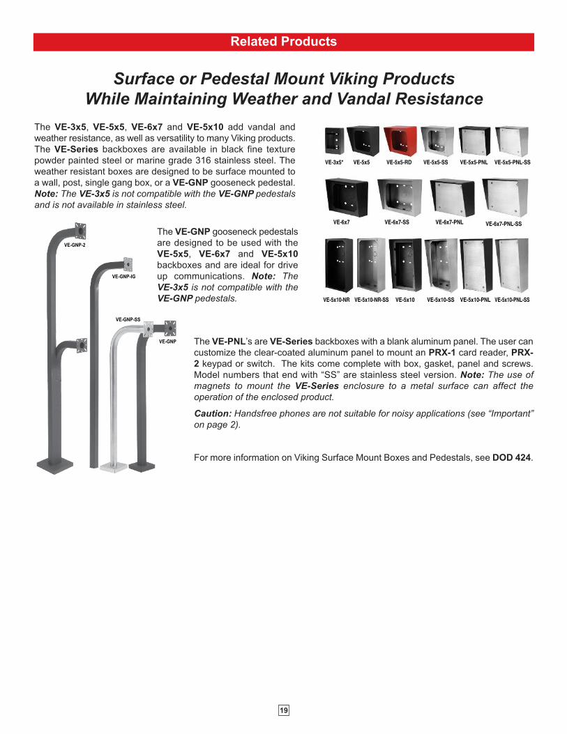
Surface or Pedestal Mount Viking Products
While Maintaining Weather and Vandal Resistance
VE-5x5 VE-5x5-SSVE-5x5-RD VE-5x5-PNL VE-5x5-PNL-SS
VE-6x7 VE-6x7-SS VE-6x7-PNL VE-6x7-PNL-SS
VE-5x10 VE-5x10-SS VE-5x10-PNL VE-5x10-PNL-SS
VE-3x5*
VE-5x10-NR VE-5x10-NR-SS
The VE-PNL’s are VE-Series backboxes with a blank aluminum panel. The user can
customize the clear-coated aluminum panel to mount an PRX-1 card reader, PRX-
2 keypad or switch. The kits come complete with box, gasket, panel and screws.
Model numbers that end with “SS” are stainless steel version. Note: The use of
magnets to mount the VE-Series enclosure to a metal surface can affect the
operation of the enclosed product.
Caution: Handsfree phones are not suitable for noisy applications (see “Important”
on page 2).
For more information on Viking Surface Mount Boxes and Pedestals, see DOD 424.
The VE-3x5, VE-5x5, VE-6x7 and VE-5x10 add vandal and
weather resistance, as well as versatility to many Viking products.
The VE-Series backboxes are available in black fine texture
powder painted steel or marine grade 316 stainless steel. The
weather resistant boxes are designed to be surface mounted to
a wall, post, single gang box, or a VE-GNP gooseneck pedestal.
Note: The VE-3x5 is not compatible with the VE-GNP pedestals
and is not available in stainless steel.
The VE-GNP gooseneck pedestals
are designed to be used with the
VE-5x5, VE-6x7 and VE-5x10
backboxes and are ideal for drive
up communications. Note: The
VE-3x5 is not compatible with the
VE-GNP pedestals.
20
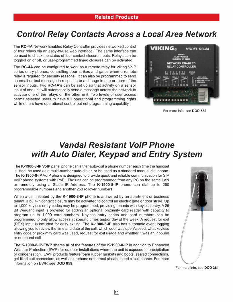
Control Relay Contacts Across a Local Area Network
The RC-4A Network Enabled Relay Controller provides networked control
of four relays via an easy-to-use web interface. The same interface can
be used to check the status of four contact closure inputs. Relays can be
toggled on or off, or user-programmed timed closures can be activated.
The RC-4A can be configured to work as a remote relay for Viking VoIP
series entry phones, controlling door strikes and gates when a remote
relay is required for security reasons. It can also be programmed to send
an email or text message in response to a change in one or more of the
sensor inputs. Two RC-4A’s can be set up so that activity on a sensor
input of one unit will automatically send a message across the network to
activate one of the relays on the other unit. Two levels of user access
permit selected users to have full operational and programming rights
while others have operational control but not programming capability.
Related Products
For more info, see DOD 582
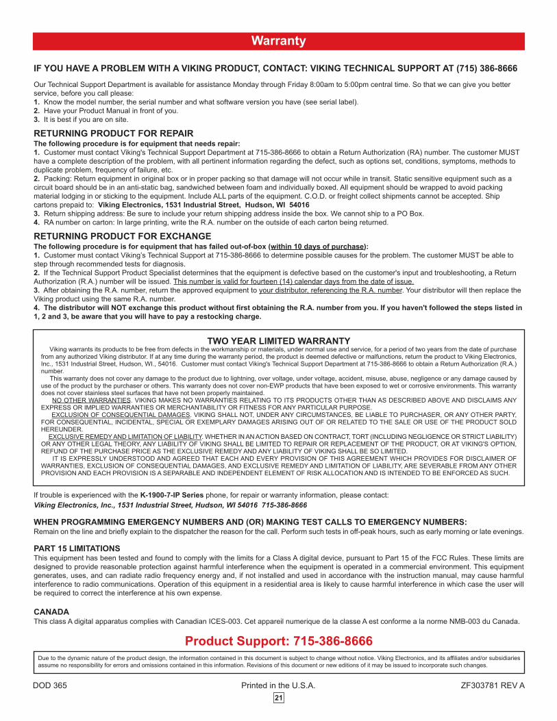
For more info, see DOD 361
The K-1900-8-IP VoIP panel phone can either auto-dial a phone number each time the handset
is lifted, be used as a multi-number auto-dialer, or be used as a standard manual dial phone.
The K-1900-8-IP VoIP phone is designed to provide quick and reliable communication for SIP
VoIP phone systems with PoE. The unit can be programmed from any PC on the same LAN
or remotely using a Static IP Address. The K-1900-8-IP phone can dial up to 250
programmable numbers and another 250 rollover numbers.
When a call initiated by the K-1900-8-IP phone is answered by an apartment or business
tenant, a built-in contact closure may be activated to control an electric gate or door strike. Up
to 1,000 keyless entry codes may be programmed, providing tenants with keyless entry. A 26
Bit Wiegand input is provided for adding an optional proximity card reader with capacity to
program up to 1,000 card numbers. Keyless entry codes and card numbers can be
programmed to only allow access at specific times and/or day of the week. A request for exit
(REX) input is included for easy exiting. The K-1900-8-IP also has automatic event logging
allowing you to review the time and date of the call, which door was open/closed, what keyless
entry code or proximity card was used, request for exit usage and whether it was an inbound
or outbound call.
The K-1900-8-IP-EWP shares all of the features of the K-1900-8-IP in addition to Enhanced
Weather Protection (EWP) for outdoor installations where the unit is exposed to precipitation
or condensation. EWP products feature foam rubber gaskets and boots, sealed connections,
gel-filled butt connectors, as well as urethane or thermal plastic potted circuit boards. For more
information on EWP, see DOD 859.
Vandal Resistant VoIP Phone with Auto Dialer, Keypad and Entry System
21
Printed in the U.S.A. ZF303781 REV A
Due to the dynamic nature of the product design, the information contained in this document is subject to change without notice. Viking Electronics, and its affiliates and/or subsidiaries
assume no responsibility for errors and omissions contained in this information. Revisions of this document or new editions of it may be issued to incorporate such changes.
DOD 365
Product Support: 715-386-8666
If trouble is experienced with the K-1900-7-IP Series phone, for repair or warranty information, please contact:
Viking Electronics, Inc., 1531 Industrial Street, Hudson, WI 54016 715-386-8666
WHEN PROGRAMMING EMERGENCY NUMBERS AND (OR) MAKING TEST CALLS TO EMERGENCY NUMBERS:Remain on the line and briefly explain to the dispatcher the reason for the call. Perform such tests in off-peak hours, such as early morning or late evenings.
PART 15 LIMITATIONSThis equipment has been tested and found to comply with the limits for a Class A digital device, pursuant to Part 15 of the FCC Rules. These limits are
designed to provide reasonable protection against harmful interference when the equipment is operated in a commercial environment. This equipment
generates, uses, and can radiate radio frequency energy and, if not installed and used in accordance with the instruction manual, may cause harmful
interference to radio communications. Operation of this equipment in a residential area is likely to cause harmful interference in which case the user will
be required to correct the interference at his own expense.
CANADAThis class A digital apparatus complies with Canadian ICES-003. Cet appareil numerique de la classe A est conforme a la norme NMB-003 du Canada.
Warranty
IF YOU HAVE A PROBLEM WITH A VIKING PRODUCT, CONTACT: VIKING TECHNICAL SUPPORT AT (715) 386-8666
Our Technical Support Department is available for assistance Monday through Friday 8:00am to 5:00pm central time. So that we can give you better
service, before you call please:
1. Know the model number, the serial number and what software version you have (see serial label).
2. Have your Product Manual in front of you.
3. It is best if you are on site.
RETURNING PRODUCT FOR REPAIRThe following procedure is for equipment that needs repair:
1. Customer must contact Viking's Technical Support Department at 715-386-8666 to obtain a Return Authorization (RA) number. The customer MUST
have a complete description of the problem, with all pertinent information regarding the defect, such as options set, conditions, symptoms, methods to
duplicate problem, frequency of failure, etc.
2. Packing: Return equipment in original box or in proper packing so that damage will not occur while in transit. Static sensitive equipment such as a
circuit board should be in an anti-static bag, sandwiched between foam and individually boxed. All equipment should be wrapped to avoid packing
material lodging in or sticking to the equipment. Include ALL parts of the equipment. C.O.D. or freight collect shipments cannot be accepted. Ship
cartons prepaid to: Viking Electronics, 1531 Industrial Street, Hudson, WI 54016
3. Return shipping address: Be sure to include your return shipping address inside the box. We cannot ship to a PO Box.
4. RA number on carton: In large printing, write the R.A. number on the outside of each carton being returned.
RETURNING PRODUCT FOR EXCHANGEThe following procedure is for equipment that has failed out-of-box (within 10 days of purchase):
1. Customer must contact Viking’s Technical Support at 715-386-8666 to determine possible causes for the problem. The customer MUST be able to
step through recommended tests for diagnosis.
2. If the Technical Support Product Specialist determines that the equipment is defective based on the customer's input and troubleshooting, a Return
Authorization (R.A.) number will be issued. This number is valid for fourteen (14) calendar days from the date of issue.
3. After obtaining the R.A. number, return the approved equipment to your distributor, referencing the R.A. number. Your distributor will then replace the
Viking product using the same R.A. number.
4. The distributor will NOT exchange this product without first obtaining the R.A. number from you. If you haven't followed the steps listed in
1, 2 and 3, be aware that you will have to pay a restocking charge.
TWO YEAR LIMITED WARRANTYViking warrants its products to be free from defects in the workmanship or materials, under normal use and service, for a period of two years from the date of purchase
from any authorized Viking distributor. If at any time during the warranty period, the product is deemed defective or malfunctions, return the product to Viking Electronics,Inc., 1531 Industrial Street, Hudson, WI., 54016. Customer must contact Viking's Technical Support Department at 715-386-8666 to obtain a Return Authorization (R.A.)number.
This warranty does not cover any damage to the product due to lightning, over voltage, under voltage, accident, misuse, abuse, negligence or any damage caused byuse of the product by the purchaser or others. This warranty does not cover non-EWP products that have been exposed to wet or corrosive environments. This warrantydoes not cover stainless steel surfaces that have not been properly maintained.
NO OTHER WARRANTIES. VIKING MAKES NO WARRANTIES RELATING TO ITS PRODUCTS OTHER THAN AS DESCRIBED ABOVE AND DISCLAIMS ANYEXPRESS OR IMPLIED WARRANTIES OR MERCHANTABILITY OR FITNESS FOR ANY PARTICULAR PURPOSE.
EXCLUSION OF CONSEQUENTIAL DAMAGES. VIKING SHALL NOT, UNDER ANY CIRCUMSTANCES, BE LIABLE TO PURCHASER, OR ANY OTHER PARTY,FOR CONSEQUENTIAL, INCIDENTAL, SPECIAL OR EXEMPLARY DAMAGES ARISING OUT OF OR RELATED TO THE SALE OR USE OF THE PRODUCT SOLDHEREUNDER.
EXCLUSIVE REMEDY AND LIMITATION OF LIABILITY. WHETHER IN AN ACTION BASED ON CONTRACT, TORT (INCLUDING NEGLIGENCE OR STRICT LIABILITY)OR ANY OTHER LEGAL THEORY, ANY LIABILITY OF VIKING SHALL BE LIMITED TO REPAIR OR REPLACEMENT OF THE PRODUCT, OR AT VIKING'S OPTION,REFUND OF THE PURCHASE PRICE AS THE EXCLUSIVE REMEDY AND ANY LIABILITY OF VIKING SHALL BE SO LIMITED.
IT IS EXPRESSLY UNDERSTOOD AND AGREED THAT EACH AND EVERY PROVISION OF THIS AGREEMENT WHICH PROVIDES FOR DISCLAIMER OFWARRANTIES, EXCLUSION OF CONSEQUENTIAL DAMAGES, AND EXCLUSIVE REMEDY AND LIMITATION OF LIABILITY, ARE SEVERABLE FROM ANY OTHERPROVISION AND EACH PROVISION IS A SEPARABLE AND INDEPENDENT ELEMENT OF RISK ALLOCATION AND IS INTENDED TO BE ENFORCED AS SUCH.

![Ambition Academy Behal AMBITIO N ACADEMY BEHALpolicejobnews.in/wp-content/uploads/2018/08/TEST-14.pdf · ftl fnu vki [kqn ij gl ldks] le> tkvks vki lQy gksrs tk jgs gksA AMBITION](https://img.pdfslide.net/doc/110x75/5cad474b88c9932b7a8da787/ambition-academy-behal-ambitio-n-academy-ftl-fnu-vki-kqn-ij-gl-ldks-le-tkvks.jpg)


![v/;k; & 6scert.cg.gov.in/dedodldistance201213...gSaA ';ke dh cksyh lkQ ugha gS] igyh ckj vki mldh ckr ugha le> ldrs ysfdu tc vki ,d ckj mlls ckr djus yxs rks vki mldh cksyh le> ldrs](https://img.pdfslide.net/doc/110x75/5ff9cdb6270f0c2b9a0b73b1/vk-gsaa-ke-dh-cksyh-lkq-ugha-gs-igyh-ckj-vki-mldh-ckr-ugha-le.jpg)