Embed Size (px)
Citation preview


Do-more Designer Ladder Logic Programming – 1 of 13
Rung 1-3
These first couple of rungs set up our logic for control of
an auto cycle. A Cycle Start and Stop push button, along
with an Auto/Manual selector switch are programmed on
the C-more Touch Panel.
As long as the Auto Cycle is selected, and we have
pressed the Cycle Start PB, internal Auto_Cycle control
relay C10 will be locked in.
The Cycle_Not_Comp control relay circuit is used to
allow an index cycle to complete by monitoring if the
stepper motor is moving. If taken out of Auto_Cycle,
C11 will stay locked in until Motor_in_Motion X38
signal opens.

Rung 4-5
The 4-20mA output from the Laser Distance Sensor
is scaled to represent a measured distance of 1.18
inches to 3.15 inches. The Scale instruction takes
the 0 to 4095 value from the analog input module
and converts it to show the actual distance in
inches.
With no part in loaded in the rotary disk position 1,
the Laser Distance sensor will indicate 1 distance of
approximately 3.15 inches. The part will be seen as
a distance of greater than 2.85 inches, but not more
than 2.45 inches.
Do-more Designer Ladder Logic Programming – 2 of 13

The instructions shown here take the 9-bit output from
the 360 degree absolute encoder and converts it to read
as 1 to 360 degrees of rotation.
The first step is to set up the 9 inputs, X8 thru X16, into
a one word value. This is accomplished with the INIT
instruction.
The output from the absolute encoder is Gray Code, and
is converted to an integer value using the GRAY
instruction.
There is a fixed offset value of 76 that is associated with
the 360 degree encoder, so a MATH instruction is used
to remove the offset value.
Our application calls for the degrees to read 1 to 360 as
the rotary disk moves in a counter clockwise direction,
so a SCALE instruction is used to reverse and change
the reading. Rung 6
Do-more Designer Ladder Logic Programming – 3 of 13
Do-more Designer Ladder Logic Programming – 4 of 13
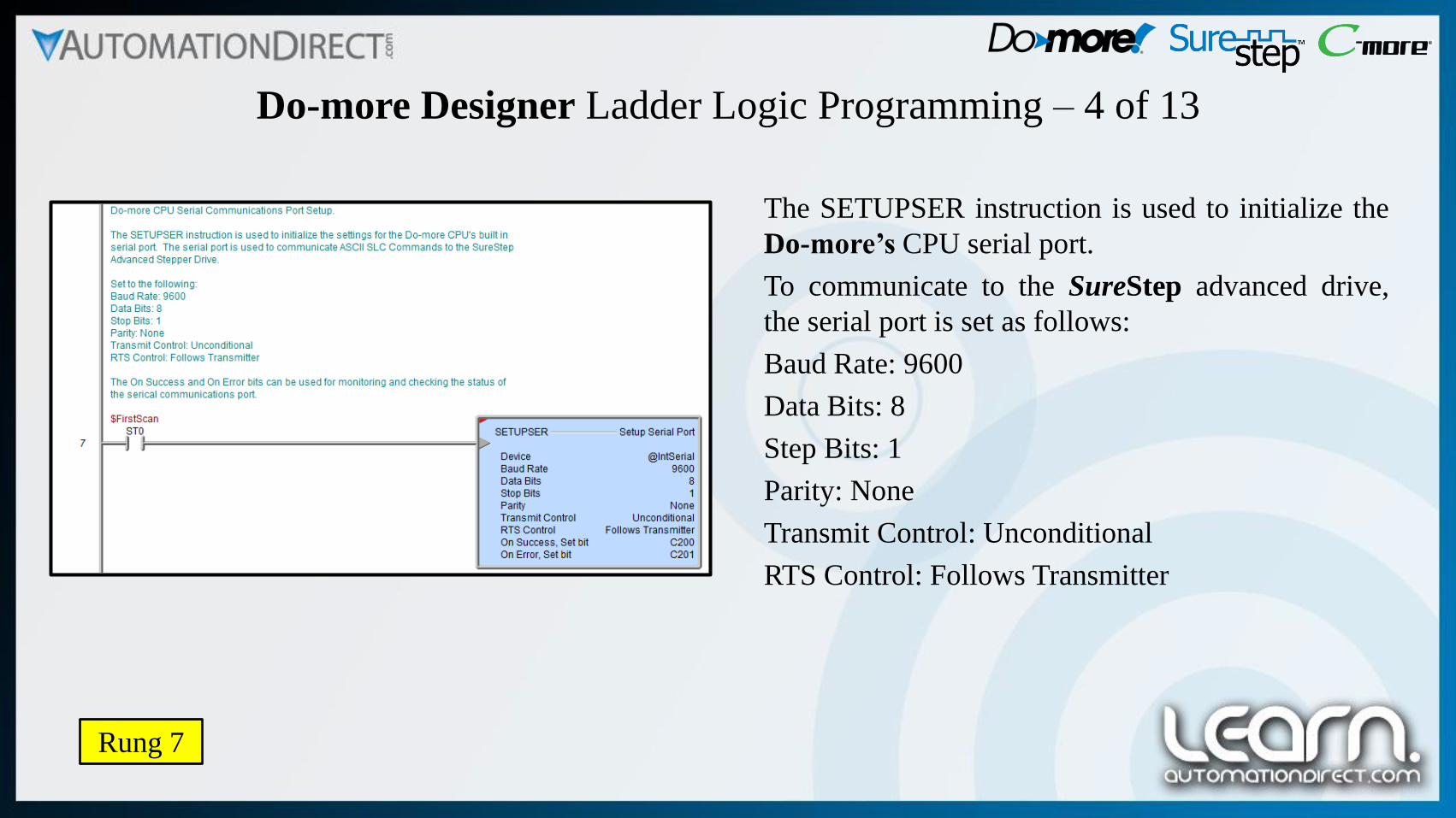
The SETUPSER instruction is used to initialize the
Do-more’s CPU serial port.
To communicate to the SureStep advanced drive,
the serial port is set as follows:
Baud Rate: 9600
Data Bits: 8
Step Bits: 1
Parity: None
Transmit Control: Unconditional
RTS Control: Follows Transmitter
Rung 7

Do-more Designer Ladder Logic Programming – 5 of 13
Rung 8-9
The following two rungs control the Rotary Index Table’s indexing function. The TMR timer shown is used to
slightly delay the next index to allow the part that is loading to settle into position.
The Auto_Index_RIT internal relay C12 logic becomes true when all of the conditions are met. The requirements
are the cycle is not complete, settle timer timed out, part is loaded, and the steel/brass marble reject cycles are not
in process.

Do-more Designer Ladder Logic Programming – 6 of 13
Rung 10
Here is the logic that sends the ASCII commands of
the Serial Command Language from the Do-more’s
CPU serial port to the SureStep advanced driver’s
serial port.
This is our index move. The rotary disk has eight
positions with a pocket to accept a part at each
position. The positions are separated by 45
degrees. The stepper drive is set up to produce
36,000 steps per revolution, therefore it will take
4,500 steps to move 45 degrees.
The drives acceleration, deceleration, and velocity
rates are part of the ASCII string that is sent.
The move command is a Feed to Length type of
move.

Do-more Designer Ladder Logic Programming – 7 of 13
Rung 11
Shown here is the simple logic that is used to allow
the rotary disk to be jogged one degree at a time in
the counter clockwise direction.
The system needs to be selected in Manual Mode
by the Auto_Manual selector switch on the C-more
Touch Panel. Press the 1 Deg CCW push button on
C-more to execute.
The SCL commands are basically the same
sequence that are used for the index move as
described on the previous rung. One degree of
movement requires 100 steps.

Do-more Designer Ladder Logic Programming – 8 of 13
Rung 12
The previous rung explained the logic to jog the
rotary disk one degree counter clockwise in manual
mode.
This is the logic to jog the rotary disk one degree
clockwise in manual mode.

Do-more Designer Ladder Logic Programming – 9 of 13
Rung 13-15
This is the logic for the detection and rejection of
any steel marbles that come through the Rotary
Index Table. The steel marbles are detected at
position 2 of the rotary disk by an inductive
proximity.
A shift register, SR instruction, is used to keep track
of any steel marble reject. In our situation, the steel
marble is rejected at position 3. The reject is
handled by a pneumatic slide cylinder that retracts a
gate, allowing the steel marble to fall through a tube
into a bin.
If a reject is indicated by the Shift Register bit C65,
then the solenoid valve, Y0 output, is energized to
open the reject gate. Magnetic sensors on the slide
cylinder are used to sequence the operation.

Do-more Designer Ladder Logic Programming – 10 of 13
Rung 16-18
This is the logic for the detection and rejection of
any brass marbles that come through the Rotary
Index Table. The brass marbles are detected at
position 6 of the rotary disk by an inductive
proximity.
A shift register, SR instruction, is used to keep track
of any brass marble reject. In our situation, the
brass marble is rejected at position 7. The reject is
handled by a pneumatic slide cylinder that retracts a
gate, allowing the brass marble to fall through a
tube into a bin.
If a reject is indicated by the Shift Register bit C73,
then the solenoid valve, Y1 output, is energized to
open the reject gate. Magnetic sensors on the slide
cylinder are used to sequence the operation.
Do-more Designer Ladder Logic Programming – 11 of 13
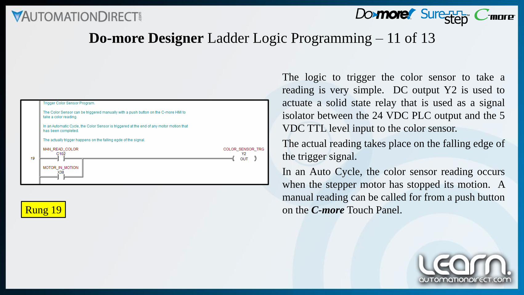
Rung 19
The logic to trigger the color sensor to take a
reading is very simple. DC output Y2 is used to
actuate a solid state relay that is used as a signal
isolator between the 24 VDC PLC output and the 5
VDC TTL level input to the color sensor.
The actual reading takes place on the falling edge of
the trigger signal.
In an Auto Cycle, the color sensor reading occurs
when the stepper motor has stopped its motion. A
manual reading can be called for from a push button
on the C-more Touch Panel.

Do-more Designer Ladder Logic Programming – 12 of 13
Rung 20-22
Because the color sensor takes a reading at Position
5 on the rotary disk, three Shift Registers are used
to keep track of the color senor’s reading shown
here as rungs 20, 21, & 22. The readings are
decoded and displayed on the C-more Touch Panel
three positions later, so at Position 8 we see the
color exiting. For example, bit 0 starts at C216, but
is decoded at C218. The logic to decode is shown
on the next slide.

Do-more Designer Ladder Logic Programming – 13 of 13
Rung 23-30
This is the logic to decode the three bits from the
color sensor that indicate the color reading from
Position 5, but indicated at the exit from the Rotary
Index Table from position 8.
The color exiting is indicated on the C-more Touch
Panel.

Link to Do-more PLC Website: http://bit.ly/28X07Hz
NOTE: A complete commented Do-more Designer
project for the Motion Control demo presented
here is available for downloading from the
AutomationDirect Video Tutorial website. Look
for the note that says Related Documents.
Do-more Designer Ladder Logic Programming – Information
There is additional information in regards to the Do-more PLC and Do-more Designer programming software
at the AboutPLCs Do-more Website. A link to the site is shown below.
The Do-more Designer project that was created for this Motion Control demonstration is fully commented and
can be downloaded for your review. See the Note below.
NOTE: Do-more Designer
Version 1.4.3 Production
software used on this demo.

Title VID Number
Part 1 of 5 – Control System Overview. L-PC-DM-STP-CM-001-1
Part 2 of 5 – Schematic Diagrams. L-PC-DM-STP-CM-001-2
Part 4 of 5 – C-more Touch Panel Programming. L-PC-DM-STP-CM-001-4
Part 5 of 5 – Operational Demonstration. L-PC-DM-STP-CM-001-5
Other available videos in this series on Motion Control.

Copyright 2016, AutomationDirect.com Incorporated/All Rights Reserved Worldwide.
Please note!
ALL AUTOMATIONDIRECT VIDEOS AND ASSOCIATED TRAINING SUPPLIES
PROVIDED IN CONNECTION THEREWITH (the “Materials”), ARE SUPPLIED “AS IS”.
These Materials are provided by our associates to assist others in learning the products we sell
and service. We make no representation, warranty or guaranty, whether expressed, implied or
statutory, regarding the Materials, including without limitation, implied warranties of
merchantability or fitness for a particular purpose. We make no representation, warranty or
guaranty that the Materials will be accurate, complete, uninterrupted, error free or non-
infringing, or are suitable for your particular application, nor do we assume any responsibility
for the use of this information in your application.