Embed Size (px)
Citation preview
OCTOBER 2015EXTERNAL CLADDING SYSTEM – HORIZONTAL PANELS
CSR CEMINTEL™
DESIGNER SERIES™ FC:502
The Cemintel Designer Series™ (CDS) pre-finished walling system combines a modern
contemporary appearance with the time and effort saving of a pre-finished panel, and a
fast, easy to install drained and ventilated cavity system to deliver outstanding exterior
cladding solutions for lightweight timber and steel stud framed applications.
2 CEMINTEL DESIGNER SERIES™ – EXTERNAL HORIZONTAL PANELS
CDS panels are pre-finished using a durable multi-layer paint
process and a NichiGuard* stain resistant coating. Panels
are tongue and groove profiled along the long edges, and
fit neatly together to form a waterproof joint. Depending on
the chosen system, some joints may be expressed and filled
with colour matched sealant.
The CDS system requires little change to Australian
building practices and is compatible with industry standard
aluminium and timber framed windows.
CDS is also easily integrated with other materials such as
Hebel PowerPanel™, Cemintel™ fibre cement and PGH brick
veneer finishes.
*NOTE: NichiGuard is available on all panels EXCEPT
Smooth Frappe and Smooth Latte.
APPLICATIONSThe Cemintel Designer Series™ (CDS) system may be used
on timber and steel framed buildings of up to two storeys
that meet the geometric limits of AS4055 : Wind loads for
housing. The system is suitable as an external cladding on
Class 1 and Class 10 buildings only.
CDS is ideal for new homes with either slab-on-ground
or elevated timber/concrete floor construction, including
duplex and townhouse construction, extensions, upper
storey additions and other applications where residential
construction techniques are appropriate.
This publication provides information on CDS External
Horizontal Panel installation only. Please refer to the
separate publication FC520 Cemintel Designer Series™
External Cladding System – Vertical Panels and FC521
Cemintel Designer Series™ Internal Wall Lining Systems for
information on these applications.
EXTERNAL HORIZONTAL PANEL SYSTEMThe Cemintel Designer Series™ external horizontal cladding
system features a ventilated and drained cavity which is
a proven and highly effective method of weatherproofing
buildings.
The Cemintel Designer Series™ external horizontal panel
system has been issued with a CodeMark™ Certificate of
Conformity No. GM-CM 30048. The certificate includes
compliance with a number of BCA clauses relating to
structure, weather resistance, bushfire construction and
thermal resistance. It applies to horizontal panels fixed
to steel or timber framing, and refers to the Technical
Manual FC502T April 2013, available on the Cemintel web
site. For current certificate information, please refer to
www.global-mark.com.au.
CONTENTSDESCRIPTION 2
APPLICATIONS 2
ADVANTAGES 3
CDS EXTERNAL CLADDING SYSTEM – HORIZONTAL
PANELS – CLIP-ON-STUD FIXING 4
DESIGN CONSIDERATIONS 5
COMPONENTS 10
INSTALLATION METHODS 14
BUILDER’S INSTALLATION CHECKLIST 17
INSTALLATION SET-OUT 18
INSTALLATION PROCEDURE 22
INSTALLATION DETAILS 23
HEALTH & SAFETY 36
WARRANTY 36
CONTACT DETAILS 36
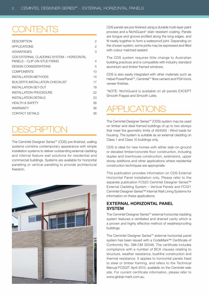
DESCRIPTIONThe Cemintel Designer Series™ (CDS) pre-finished, walling
systems combine contemporary appearance with simple
installation systems to deliver outstanding external cladding
and internal feature wall solutions for residential and
commercial buildings. Systems are available for horizontal
panelling or vertical panelling to provide architectural
freedom.
CEMINTEL DESIGNER SERIES™ – EXTERNAL HORIZONTAL PANELS 3
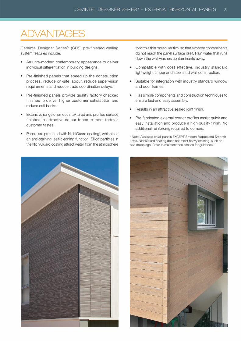
Cemintel Designer Series™ (CDS) pre-finished walling
system features include:
• An ultra-modern contemporary appearance to deliver
individual differentiation in building designs.
• Pre-finished panels that speed up the construction
process, reduce on-site labour, reduce supervision
requirements and reduce trade coordination delays.
• Pre-finished panels provide quality factory checked
finishes to deliver higher customer satisfaction and
reduce call-backs.
• Extensive range of smooth, textured and profiled surface
finishes in attractive colour tones to meet today's
customer tastes.
• Panels are protected with NichiGuard coating*, which has
an anti-staining, self-cleaning function. Silica particles in
the NichiGuard coating attract water from the atmosphere
to form a thin molecular film, so that airborne contaminants
do not reach the panel surface itself. Rain water that runs
down the wall washes contaminants away.
• Compatible with cost effective, industry standard
lightweight timber and steel stud wall construction.
• Suitable for integration with industry standard window
and door frames.
• Has simple components and construction techniques to
ensure fast and easy assembly.
• Results in an attractive sealed joint finish.
• Pre-fabricated external corner profiles assist quick and
easy installation and produce a high quality finish. No
additional reinforcing required to corners.
* Note: Available on all panels EXCEPT Smooth Frappe and Smooth
Latte. NichiGuard coating does not resist heavy staining, such as
bird droppings. Refer to maintenance section for guidance.
ADVANTAGES
4 CEMINTEL DESIGNER SERIES™ – EXTERNAL HORIZONTAL PANELS
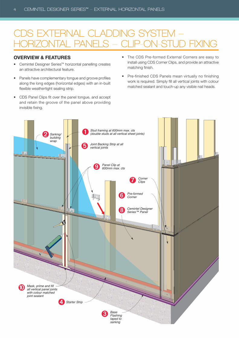
CDS EXTERNAL CLADDING SYSTEM – HORIZONTAL PANELS – CLIP-ON-STUD FIXING
Cemintel Designer Series™ Panel
Stud framing at 600mm max. cts (double studs at all vertical sheet joints)Sarking/
buildingwrap
Starter Strip
Mask, prime and fill all vertical panel joints with colour matched joint sealant
➊➋
Base Flashing taped to sarking
➌
Joint Backing Strip at all vertical joints➎
Pre-formed Corner➏
➑
➍
Corner Clips➐
Panel Clip at 600mm max. cts ➒
➓
OVERVIEW & FEATURES• Cemintel Designer Series™ horizontal panelling creates
an attractive architectural feature.
• Panels have complementary tongue and groove profiles
along the long edges (horizontal edges) with an in-built
flexible weathertight sealing strip.
• CDS Panel Clips fit over the panel tongue, and accept
and retain the groove of the panel above providing
invisible fixing.
• The CDS Pre-formed External Corners are easy to
install using CDS Corner Clips, and provide an attractive
matching finish.
• Pre-finished CDS Panels mean virtually no finishing
work is required. Simply fill all vertical joints with colour
matched sealant and touch-up any visible nail heads.
CEMINTEL DESIGNER SERIES™ – EXTERNAL HORIZONTAL PANELS 5
TERMITE PROTECTIONAs there is a wide variety of methods for managing termite
entry to buildings, and selecting the appropriate method for
any structure depends on specific risk factors and the form
of construction, measures for termite management have not
been addressed in this guide.
Refer to your local pest management service, the BCA,
AS3660 : Termite management, or your local building
authorities for more information about the requirements for
the design of a suitable termite management system.
STRUCTURAL BRACINGCDS panels are indirectly attached to the structural framing
using clips and spacers. As a consequence, they are not
designed to provide wall bracing. Bracing must be provided
in the structural framing in the normal manner by using
methods such as strap bracing or sheet bracing. Where
sheet bracing is used, the entire wall framing to be clad with
CDS panels must be sheeted to maintain a uniform fixing
plane. Note that window set-out will be affected.
SERVICESThe CDS system will accommodate services that are run
through the framing. Any notches or holes formed must be
considered in the framing design
COASTAL AREAS/CORROSIVITY ZONESThe Cemintel Designer Series™ (CDS) system may be
used in some coastal areas. Corrosivity zones are detailed
in AS4312, and CDS may be used in zones up to and
including C4 - High. In C4 corrosivity zones, face fixings
must be Class 4 or stainless steel. It is recommended that
the building designer assess the site in accordance with the
standard and local conditions.
CDS is NOT suitable for Corrosivity Zone C5 – Very High.
This includes the beachfront in regions of rough seas and
surf beaches, and inland for several hundred metres, e.g.
around Newcastle extending over half a kilometre from the
coast. It also includes aggressive industrial areas where the
environment may be acidic with a pH of less than 5.
Consideration must also be given to local weather and
topographical features that can cause an increase in the
distance that salt spray can travel beyond the limits detailed
in AS4312.
In Category C3 and above, all walls which are protected
by soffits above must be washed down twice per year,
to remove salt and debris build-up, particularly around
window/door openings.
DESIGN CONSIDERATIONS This guide represents good practice, though it is not intended
as an exhaustive statement of all relevant information. It
remains the responsibility of the building designer to verify
that the Cemintel Designer Series™ cladding system is
suitable for the particular requirements of any given project.
This guide should be read in conjunction with the Building
Code of Australia (BCA).
FRAMINGThe Cemintel Designer Series™ (CDS) Horizontal Panel
system has been evaluated for use in all Australian wind
zones up to and including N6 and Cyclonic C3.
Designer Series™ can be fixed horizontally to timber or steel
framing. As a minimum requirement, framing shall be in
accordance with the following standard:
• AS1684 – Residential Timber-Framed Construction.
• AS/NZS4600 – Cold-Formed Steel Structures.
Timber shall be seasoned or have reached an equilibrium
moisture content of 16% or less at the time of framing.
Unseasoned timber is not recommended.
The design and construction of the steel frames should
be considered in conjunction with the advice from the
manufacturer. In highly corrosive environments, appropriate
measures should be taken to protect the frame from
corrosion.
DRAINED & VENTILATED CAVITY SYSTEMCemintel Designer Series™ uses a drained and ventilated
cavity system which provides an effective alternative to
manage the migration of water vapour through stud framed
wall systems. The cavity is created by fixing Designer
Series™ panels to the face of framing, over a layer of suitable
wall wrap/sarking, with proprietary Designer Series™ Fixing
Clips and Spacer Strips. Ventilation must be maintained
at the top and base of each wall section. Refer to detail
drawings.
6 CEMINTEL DESIGNER SERIES™ – EXTERNAL HORIZONTAL PANELS
BUSHFIRE ZONE & FIRE RATED EXTERNAL WALLSCemintel™ fibre cement cladding products are suitable for
use in bushfire zones in accordance with AS3959, and for
fire rated external walls in accordance with the Building
Code of Australia (BCA).
Cemintel™ Designer Series has been tested to AS1530.8.1
and passed the requirements for BAL: A-40. Test report
EWFA 2593800. The wall system therefore complies with
the requirements of AS3959 Section 8 ‘Construction for
Bushfire Attack Level 40 (BAL-40)’ for an external wall.
For additional bush fire requirements, refer to AS3959
Construction of buildings in bushfire prone areas, and to the
BCA Volume 1 Part 3.7.4.
CSR also offers wall systems that enable Cemintel Designer
Series™ cladding to be used as part of external fire rated
wall systems including:
• External walls in Bushfire Attack Level BAL-FZ,
• External walls to Class 1 buildings within 900mm of the
boundary including Zero-Lot walls,
• External walls adjacent an external fire source (such as
an Electrical Sub-Station).
For detailed information, refer to the Cemintel™ Construction
Guide for Fire Rated External Wall Systems, available from
www.cemintel.com.au.
WALL WRAP/SARKING SELECTIONTo ensure occupant comfort and protection of the building
frame, the following factors should be considered during the
selection of the correct wall wrap/sarking.
• Condensation Risk: This is a complex problem and
can occur under a variety of conditions (not just in cold
and tropical climates) so selection of the right wall wrap/
sarking needs to consider the local climate, building use
and orientation, material R-Value of the insulation, as well
as the degree and location of ventilation.
• Weather Barrier: Wind loads can produce lower air
pressures within buildings than on the outside, forcing
water through small gaps in the building envelope around
penetrations and joints, even at low wind speeds.
Careful selection of a wall wrap/sarking with the appropriate
level of vapour permeability or vapour resistance is one
key factor in reducing condensation risk. Table 1 provides
guidance on recommended wall wrap/sarking selection.
Key selection characteristics for a suitable wall wrap/sarking
are as follows:
• The wall wrap/sarking must have a ‘high’ water barrier
classification – an ‘unclassified’ rating is not suitable.
• Wall wrap/sarking must meet the requirements of
AS/NZS4200.1: Pliable building membranes and
underlays – Materials, and be installed in accordance
with AS/NZS4200.2: Pliable building membranes and
underlays – Installation requirements.
Whilst the requirement to seal joins and penetrations may
vary depending upon BCA and/or state requirements, CSR
recommends sealing/taping all joints in the external wall
wrap/sarking to maintain vapour performance and draught
proofing effectiveness, as well as to ensure water barrier
integrity. As there are a number of factors that need to be
considered in assessing and managing condensation risk, it
is recommended that designers undertake a condensation
risk analysis prior to wall wrap/sarking selection as part of
the building design. Additional literature on this subject is
available from CSIRO/BRANZ/ASHRAE/ABCB and CSR
DesignLINK can help with this assessment.
INSULATIONIt is recommended that insulation values above the minimum
be chosen for energy conservation and occupant comfort.
Insulation also improves the acoustic performance of the
wall against outside noise.
The level of insulation provided in a wall is described by its
R-value. The higher the R-value the greater the insulation
provided.
R-values for some systems are given in the Thermal
Performance Selection, Table 2 on page 7.
Refer to 'Components' for product information.
Table 1: Guidance on Wall Wrap/Sarking
Climate Guidance on wall wrap/sarking to be used behind the cladding Performance Criteria Recommended Product
Cold Climates* In cold climates where the risk of condensation is high, vapour permeable membranes should always be installed on the cold external side of the insulation.
Vapour Permeability > 2.5µg/N.s
Enviroseal ProctorWrap RW or CW
Temperate and inland climate zones
It is recommended to use vapour permeable membranes to avoid creating a seasonal moisture trap and to allow drying in either direction – interior or exterior.
Vapour Permeability > 2.5µg/N.s
Enviroseal ProctorWrap RW or CW
Warm humid coastal and tropical climates
Where vapour flow is typically inward, such as where the building is air-conditioned, membrane should be non-permeable.
Vapour Resistance > 7MNs/g
Thermoseal Resiwrap or Thermoseal Wall Wrap or Thermoseal 733
* For alpine areas and buildings that have high internal levels of humidity (such as indoor swimming pool areas), please contact CSR Bradford for
project specific technical advice.
CEMINTEL DESIGNER SERIES™ – EXTERNAL HORIZONTAL PANELS 7
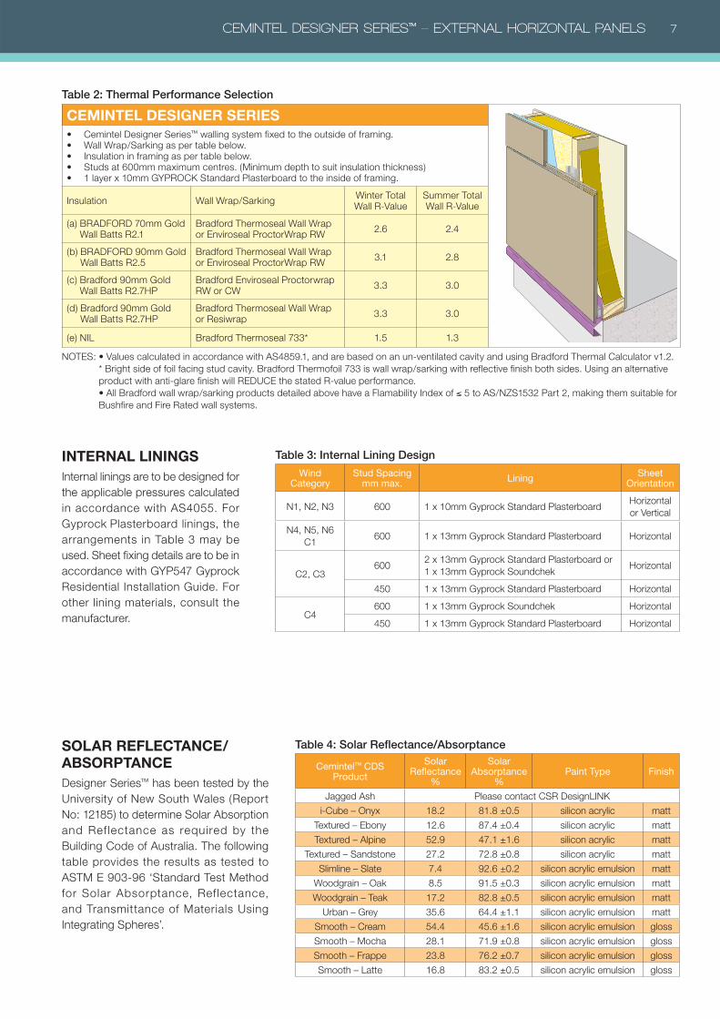
SOLAR REFLECTANCE/ABSORPTANCEDesigner Series™ has been tested by the
University of New South Wales (Report
No: 12185) to determine Solar Absorption
and Ref lectance as required by the
Building Code of Australia. The following
table provides the results as tested to
ASTM E 903-96 ‘Standard Test Method
for Solar Absorptance, Ref lectance,
and Transmittance of Materials Using
Integrating Spheres’.
INTERNAL LININGSInternal linings are to be designed for
the applicable pressures calculated
in accordance with AS4055. For
Gyprock Plasterboard linings, the
arrangements in Table 3 may be
used. Sheet fixing details are to be in
accordance with GYP547 Gyprock
Residential Installation Guide. For
other lining materials, consult the
manufacturer.
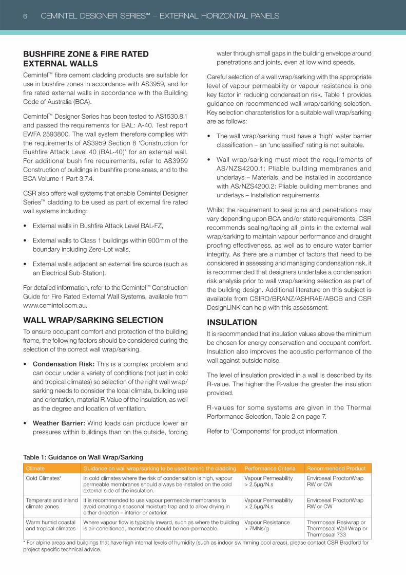
Table 2: Thermal Performance Selection
CEMINTEL DESIGNER SERIES• Cemintel Designer Series™ walling system fixed to the outside of framing. • Wall Wrap/Sarking as per table below.• Insulation in framing as per table below.• Studs at 600mm maximum centres. (Minimum depth to suit insulation thickness)• 1 layer x 10mm GYPROCK Standard Plasterboard to the inside of framing.
Insulation Wall Wrap/SarkingWinter Total Wall R-Value
Summer Total Wall R-Value
(a) BRADFORD 70mm Gold Wall Batts R2.1
Bradford Thermoseal Wall Wrap or Enviroseal ProctorWrap RW
2.6 2.4
(b) BRADFORD 90mm Gold Wall Batts R2.5
Bradford Thermoseal Wall Wrap or Enviroseal ProctorWrap RW
3.1 2.8
(c) Bradford 90mm Gold Wall Batts R2.7HP
Bradford Enviroseal Proctorwrap RW or CW
3.3 3.0
(d) Bradford 90mm Gold Wall Batts R2.7HP
Bradford Thermoseal Wall Wrap or Resiwrap
3.3 3.0
(e) NIL Bradford Thermoseal 733* 1.5 1.3
NOTES: • Values calculated in accordance with AS4859.1, and are based on an un-ventilated cavity and using Bradford Thermal Calculator v1.2.
* Bright side of foil facing stud cavity. Bradford Thermofoil 733 is wall wrap/sarking with reflective finish both sides. Using an alternative
product with anti-glare finish will REDUCE the stated R-value performance.
• All Bradford wall wrap/sarking products detailed above have a Flamability Index of ≤ 5 to AS/NZS1532 Part 2, making them suitable for
Bushfire and Fire Rated wall systems.
Table 3: Internal Lining Design
Wind Category
Stud Spacingmm max.
LiningSheet
Orientation
N1, N2, N3 600 1 x 10mm Gyprock Standard PlasterboardHorizontal
or Vertical
N4, N5, N6
C1600 1 x 13mm Gyprock Standard Plasterboard Horizontal
C2, C3600
2 x 13mm Gyprock Standard Plasterboard or
1 x 13mm Gyprock SoundchekHorizontal
450 1 x 13mm Gyprock Standard Plasterboard Horizontal
C4600 1 x 13mm Gyprock Soundchek Horizontal
450 1 x 13mm Gyprock Standard Plasterboard Horizontal
Table 4: Solar Reflectance/Absorptance
Cemintel™ CDS Product
Solar Reflectance
%
Solar Absorptance
%Paint Type Finish
Jagged Ash Please contact CSR DesignLINK
i-Cube – Onyx 18.2 81.8 ±0.5 silicon acrylic matt
Textured – Ebony 12.6 87.4 ±0.4 silicon acrylic matt
Textured – Alpine 52.9 47.1 ±1.6 silicon acrylic matt
Textured – Sandstone 27.2 72.8 ±0.8 silicon acrylic matt
Slimline – Slate 7.4 92.6 ±0.2 silicon acrylic emulsion matt
Woodgrain – Oak 8.5 91.5 ±0.3 silicon acrylic emulsion matt
Woodgrain – Teak 17.2 82.8 ±0.5 silicon acrylic emulsion matt
Urban – Grey 35.6 64.4 ±1.1 silicon acrylic emulsion matt
Smooth – Cream 54.4 45.6 ±1.6 silicon acrylic emulsion gloss
Smooth – Mocha 28.1 71.9 ±0.8 silicon acrylic emulsion gloss
Smooth – Frappe 23.8 76.2 ±0.7 silicon acrylic emulsion gloss
Smooth – Latte 16.8 83.2 ±0.5 silicon acrylic emulsion gloss
8 CEMINTEL DESIGNER SERIES™ – EXTERNAL HORIZONTAL PANELS
WINDOW SELECTIONThe CDS system is designed to accept standard aluminium
or timber framed windows and doors. Aluminium windows
MUST NOT have sill drain holes which can direct water into
the wall cavity. Jamb flashing is recommended in all cases.
Consideration must be given to the total depth of the wall
to ensure the required clearance is provided at the window
jamb to accommodate the panels. As per normal industry
practice, reveal depth is usually varied to adjust the window
location.
Elements that affect window/door installations include the
depth of the stud framing, the thickness of internal linings,
the depth and design of the chosen window frame, the
depth of the timber reveal and the total depth of the chosen
Designer Series™ cladding system and support framing.
Refer to typical window installation details later in this guide.
BUILDING RENOVATIONSWhen undertaking building renovations, remove all cladding
and wall wrap/sarking from the original wall framing. Ensure
the condition of the framing is in accordance with current
applicable requirements. Install additional framing as
required, wall wrap/sarking and flashings as per details in
this publication. Install the CDS system in accordance with
all requirements in this publication.
BUILDING ADDITIONSWhen undertaking building additions, a movement control
joint must be installed at the junction of the current framing
and new framing. The current and new framing and cladding
systems must be discontinuous at this control joint. Refer to
installation details later in this publication.
LIMITATIONSThe CDS system is unsuitable for the following applications:
panels with non-vertical face (e.g. parapet capping); wet
areas such as bathrooms and water features; chimney
cladding; exposure to temperatures over 50°C; non-vented
parapet cladding; contact with standing snow or ice.
Do NOT apply tiles or other materials to the face of
the panels.
MAINTENANCEThe durability of the Designer Series™ system can be
enhanced by periodic inspection and maintenance.
Inspections should include examination of the coatings,
flashings, and seals. Any cracked or damaged finish or
seals which would allow water ingress, must be repaired
immediately by resealing the affected area, or by removing
the panel and replacing sealant. Any damaged flashings,
sheets or sealant must be replaced as for new work.
Regularly inspect panel surfaces and follow wash-down
procedures when required. Small blemishes can be repaired
using CDS Touch-up Paint or other approved paint.
Ensure ventilation and drainage gaps between panels and
flashings are clear of any debris.
Surface deterioration may occur after extended exposure to
UV radiation. To prevent this, the surface can be washed-
down and coated with a proprietary clear finish to restore
surface protection. Subject to UV levels, this process should
occur every 10 years, however particular attention should be
paid to panels installed in areas with high UV levels where
more frequent recoating may be required.
WASH-DOWNWhen cleaning panels, use no more than 700psi
(50kg/cm2) of water pressure at 3m to 3.5m distance from
the face. Water pressure should be applied downward to
avoid forcing water into tongue and groove joints.
Use neutral detergent with a soft brush when removing dirty
spots from a panel. When diluting the neutral detergent,
follow the manufacture’s instructions, and use the weakest
solution possible.
GRAFFITI PROTECTIONFor walls requiring anti-graf f iti protection, Cemintel
recommends the application of Wattyl™ Poly U-400 Anti-
Graffiti Clear. Please refer to Wattlyl™ for coating instructions
and the warranty conditions of this product.
RECOATINGThe CDS system utilises a multi-layered coating system
designed to provide long lasting performance, and can
be recoated with a proprietary clear finish to prevent
deterioration.
If recoating in an alternative colour is desired, Cemintel
recommends the use of 1 coat of Wattyl™ Aquaprep Primer
Sealer Undercoat and 2 coats of Wattyl Solagard™.
Prior to any recoating, panels should be washed down, as
per the maintenance instructions, and the coating should
be applied as per Wattyl® instructions.
Cemintel recommends that only Designer Series Smooth
and Woodgrain are recoated with an alternative colour.
CEMINTEL DESIGNER SERIES™ – EXTERNAL HORIZONTAL PANELS 9
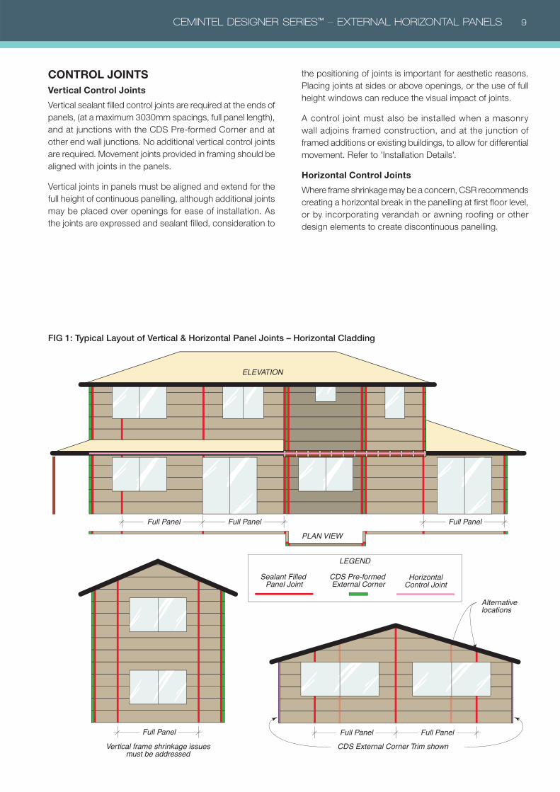
FIG 1: Typical Layout of Vertical & Horizontal Panel Joints – Horizontal Cladding
Full Panel Full Panel
Full Panel Full Panel
Full Panel
Alternative locations
Full Panel
Sealant Filled Panel Joint
LEGEND
PLAN VIEW
CDS Pre-formed External Corner
ELEVATION
Vertical frame shrinkage issues must be addressed
CDS External Corner Trim shown
HorizontalControl Joint
CONTROL JOINTS Vertical Control Joints
Vertical sealant filled control joints are required at the ends of
panels, (at a maximum 3030mm spacings, full panel length),
and at junctions with the CDS Pre-formed Corner and at
other end wall junctions. No additional vertical control joints
are required. Movement joints provided in framing should be
aligned with joints in the panels.
Vertical joints in panels must be aligned and extend for the
full height of continuous panelling, although additional joints
may be placed over openings for ease of installation. As
the joints are expressed and sealant filled, consideration to
the positioning of joints is important for aesthetic reasons.
Placing joints at sides or above openings, or the use of full
height windows can reduce the visual impact of joints.
A control joint must also be installed when a masonry
wall adjoins framed construction, and at the junction of
framed additions or existing buildings, to allow for differential
movement. Refer to 'Installation Details'.
Horizontal Control Joints
Where frame shrinkage may be a concern, CSR recommends
creating a horizontal break in the panelling at first floor level,
or by incorporating verandah or awning roofing or other
design elements to create discontinuous panelling.
10 CEMINTEL DESIGNER SERIES™ – EXTERNAL HORIZONTAL PANELS
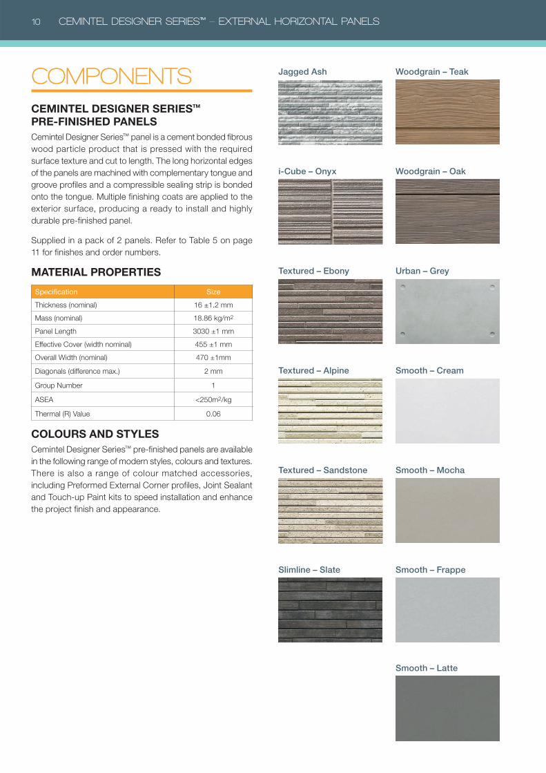
COMPONENTSCEMINTEL DESIGNER SERIES™ PRE-FINISHED PANELSCemintel Designer Series™ panel is a cement bonded fibrous
wood particle product that is pressed with the required
surface texture and cut to length. The long horizontal edges
of the panels are machined with complementary tongue and
groove profiles and a compressible sealing strip is bonded
onto the tongue. Multiple finishing coats are applied to the
exterior surface, producing a ready to install and highly
durable pre-finished panel.
Supplied in a pack of 2 panels. Refer to Table 5 on page
11 for finishes and order numbers.
MATERIAL PROPERTIES
Specification Size
Thickness (nominal) 16 ±1.2 mm
Mass (nominal) 18.86 kg/m2
Panel Length 3030 ±1 mm
Effective Cover (width nominal) 455 ±1 mm
Overall Width (nominal) 470 ±1mm
Diagonals (difference max.) 2 mm
Group Number 1
ASEA <250m2/kg
Thermal (R) Value 0.06
COLOURS AND STYLESCemintel Designer Series™ pre-finished panels are available
in the following range of modern styles, colours and textures.
There is also a range of colour matched accessories,
including Preformed External Corner profiles, Joint Sealant
and Touch-up Paint kits to speed installation and enhance
the project finish and appearance.
i-Cube – Onyx
Jagged Ash
Textured – Ebony
Slimline – Slate
Textured – Alpine
Textured – Sandstone
Woodgrain – Teak
Woodgrain – Oak
Urban – Grey
Smooth – Cream
Smooth – Mocha
Smooth – Frappe
Smooth – Latte
CEMINTEL DESIGNER SERIES™ – EXTERNAL HORIZONTAL PANELS 11
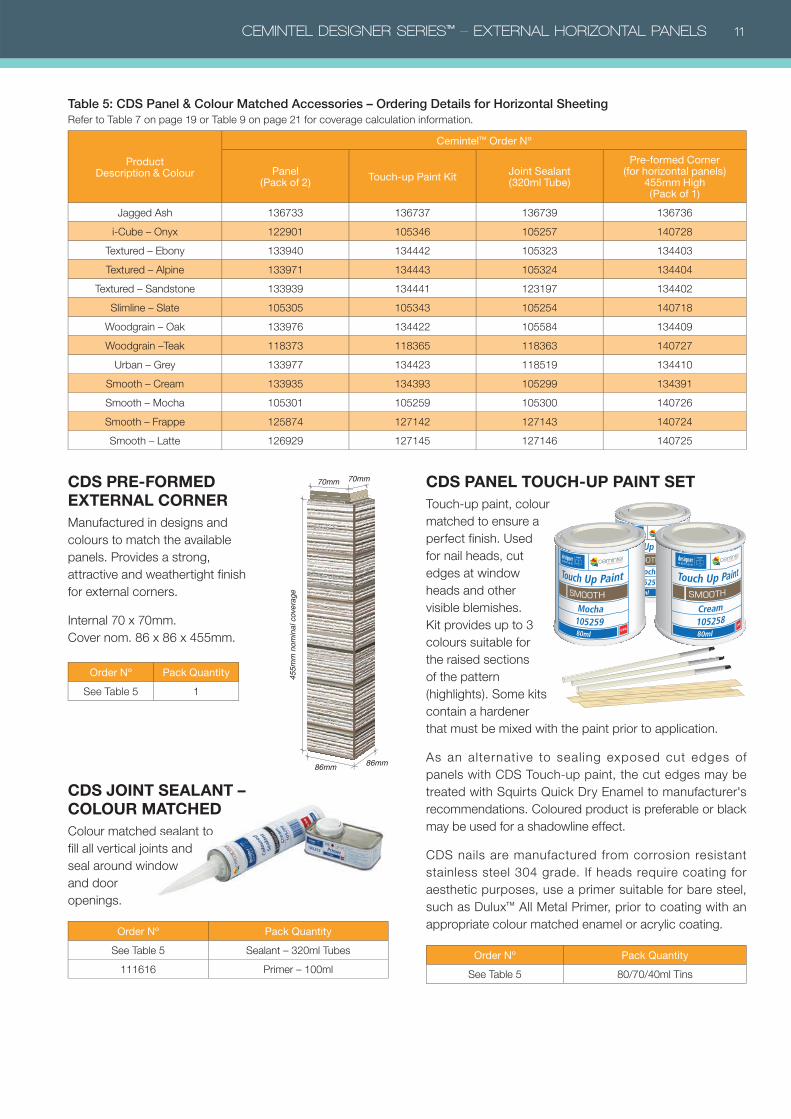
ProductDescription & Colour
Cemintel™ Order Nº
Panel (Pack of 2)
Touch-up Paint Kit Joint Sealant(320ml Tube)
Pre-formed Corner (for horizontal panels)
455mm High (Pack of 1)
Jagged Ash 136733 136737 136739 136736
i-Cube – Onyx 122901 105346 105257 140728
Textured – Ebony 133940 134442 105323 134403
Textured – Alpine 133971 134443 105324 134404
Textured – Sandstone 133939 134441 123197 134402
Slimline – Slate 105305 105343 105254 140718
Woodgrain – Oak 133976 134422 105584 134409
Woodgrain –Teak 118373 118365 118363 140727
Urban – Grey 133977 134423 118519 134410
Smooth – Cream 133935 134393 105299 134391
Smooth – Mocha 105301 105259 105300 140726
Smooth – Frappe 125874 127142 127143 140724
Smooth – Latte 126929 127145 127146 140725
Table 5: CDS Panel & Colour Matched Accessories – Ordering Details for Horizontal SheetingRefer to Table 7 on page 19 or Table 9 on page 21 for coverage calculation information.
CDS PRE-FORMED EXTERNAL CORNERManufactured in designs and
colours to match the available
panels. Provides a strong,
attractive and weathertight finish
for external corners.
Internal 70 x 70mm.
Cover nom. 86 x 86 x 455mm.
Order Nº Pack Quantity
See Table 5 1
CDS JOINT SEALANT – COLOUR MATCHED Colour matched sealant to
fill all vertical joints and
seal around window
and door
openings.
Order Nº Pack Quantity
See Table 5 Sealant – 320ml Tubes
111616 Primer – 100ml
86mm
455m
m n
omin
al c
over
age
86mm
70mm 70mm CDS PANEL TOUCH-UP PAINT SET Touch-up paint, colour
matched to ensure a
perfect finish. Used
for nail heads, cut
edges at window
heads and other
visible blemishes.
Kit provides up to 3
colours suitable for
the raised sections
of the pattern
(highlights). Some kits
contain a hardener
that must be mixed with the paint prior to application.
As an alternative to sealing exposed cut edges of
panels with CDS Touch-up paint, the cut edges may be
treated with Squirts Quick Dry Enamel to manufacturer's
recommendations. Coloured product is preferable or black
may be used for a shadowline effect.
CDS nails are manufactured from corrosion resistant
stainless steel 304 grade. If heads require coating for
aesthetic purposes, use a primer suitable for bare steel,
such as Dulux™ All Metal Primer, prior to coating with an
appropriate colour matched enamel or acrylic coating.
Order Nº Pack Quantity
See Table 5 80/70/40ml Tins
MATCHEDd sealant to
nts and
dow
12 CEMINTEL DESIGNER SERIES™ – EXTERNAL HORIZONTAL PANELS
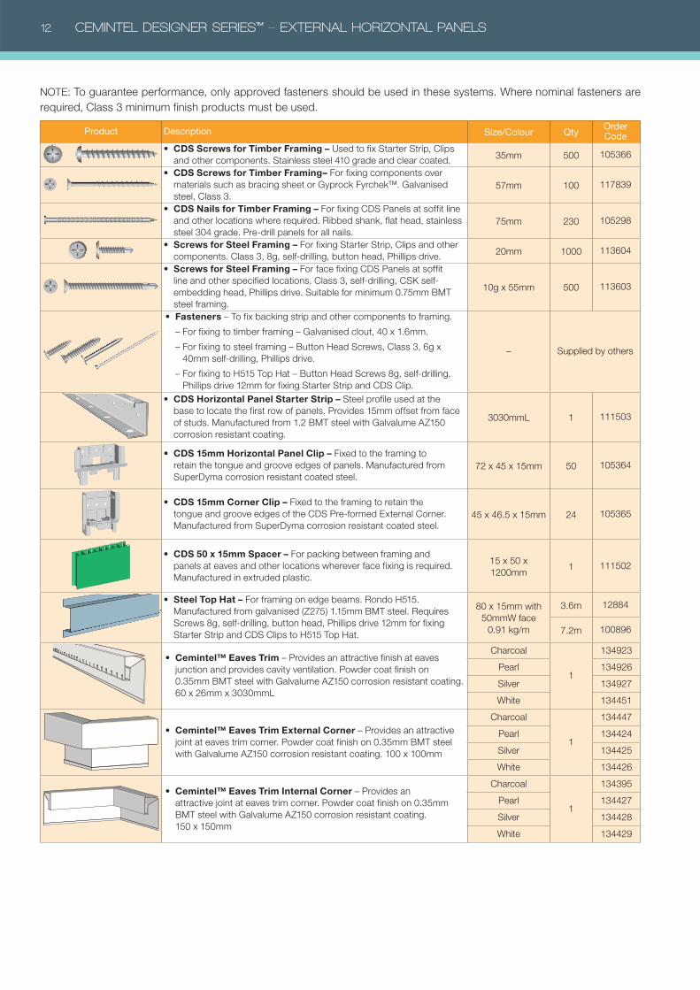
Product Description Size/Colour QtyOrder Code
• CDS Screws for Timber Framing – Used to fix Starter Strip, Clips
and other components. Stainless steel 410 grade and clear coated. 35mm 500 105366
• CDS Screws for Timber Framing– For fixing components over
materials such as bracing sheet or Gyprock Fyrchek™. Galvanised
steel, Class 3.
57mm 100 117839
• CDS Nails for Timber Framing – For fixing CDS Panels at soffit line
and other locations where required. Ribbed shank, flat head, stainless
steel 304 grade. Pre-drill panels for all nails.
75mm 230 105298
• Screws for Steel Framing – For fixing Starter Strip, Clips and other
components. Class 3, 8g, self-drilling, button head, Phillips drive. 20mm 1000 113604
• Screws for Steel Framing – For face fixing CDS Panels at soffit
line and other specified locations. Class 3, self-drilling, CSK self-
embedding head, Phillips drive. Suitable for minimum 0.75mm BMT
steel framing.
10g x 55mm 500 113603
• Fasteners – To fix backing strip and other components to framing.
– For fixing to timber framing – Galvanised clout, 40 x 1.6mm.
– For fixing to steel framing – Button Head Screws, Class 3, 6g x
40mm self-drilling, Phillips drive.
– For fixing to H515 Top Hat – Button Head Screws 8g, self-drilling,
Phillips drive 12mm for fixing Starter Strip and CDS Clip.
– Supplied by others
• CDS Horizontal Panel Starter Strip – Steel profile used at the
base to locate the first row of panels. Provides 15mm offset from face
of studs. Manufactured from 1.2 BMT steel with Galvalume AZ150
corrosion resistant coating.
3030mmL 1 111503
• CDS 15mm Horizontal Panel Clip – Fixed to the framing to
retain the tongue and groove edges of panels. Manufactured from
SuperDyma corrosion resistant coated steel.
72 x 45 x 15mm 50 105364
• CDS 15mm Corner Clip – Fixed to the framing to retain the
tongue and groove edges of the CDS Pre-formed External Corner.
Manufactured from SuperDyma corrosion resistant coated steel.
45 x 46.5 x 15mm 24 105365
• CDS 50 x 15mm Spacer – For packing between framing and
panels at eaves and other locations wherever face fixing is required.
Manufactured in extruded plastic.
15 x 50 x
1200mm1 111502
• Steel Top Hat – For framing on edge beams. Rondo H515.
Manufactured from galvanised (Z275) 1.15mm BMT steel. Requires
Screws 8g, self-drilling, button head, Phillips drive 12mm for fixing
Starter Strip and CDS Clips to H515 Top Hat.
80 x 15mm with
50mmW face
0.91 kg/m
3.6m 12884
7.2m 100896
• Cemintel™ Eaves Trim – Provides an attractive finish at eaves
junction and provides cavity ventilation. Powder coat finish on
0.35mm BMT steel with Galvalume AZ150 corrosion resistant coating.
60 x 26mm x 3030mmL
Charcoal
1
134923
Pearl 134926
Silver 134927
White 134451
• Cemintel™ Eaves Trim External Corner – Provides an attractive
joint at eaves trim corner. Powder coat finish on 0.35mm BMT steel
with Galvalume AZ150 corrosion resistant coating. 100 x 100mm
Charcoal
1
134447
Pearl 134424
Silver 134425
White 134426
• Cemintel™ Eaves Trim Internal Corner – Provides an
attractive joint at eaves trim corner. Powder coat finish on 0.35mm
BMT steel with Galvalume AZ150 corrosion resistant coating.
150 x 150mm
Charcoal
1
134395
Pearl 134427
Silver 134428
White 134429
NOTE: To guarantee performance, only approved fasteners should be used in these systems. Where nominal fasteners are
required, Class 3 minimum finish products must be used.
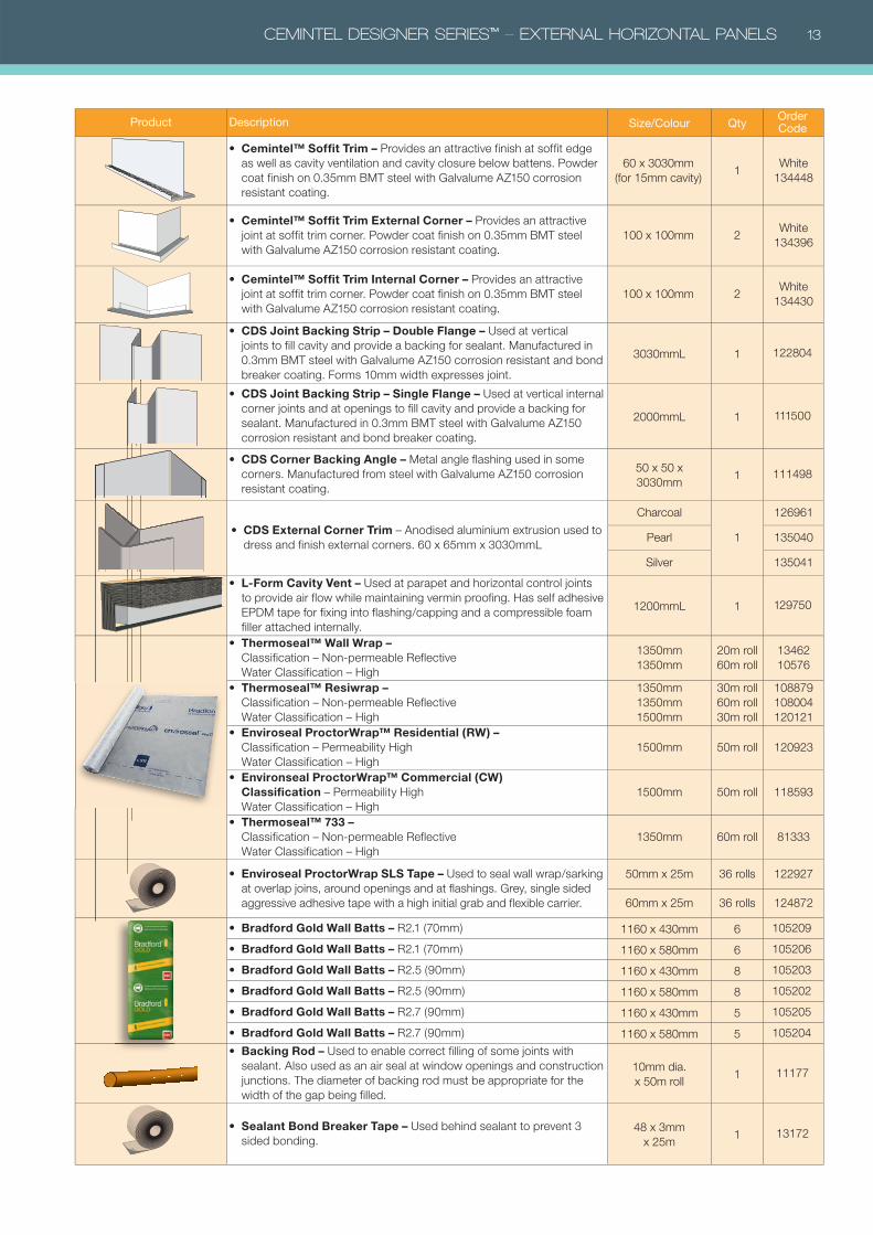
CEMINTEL DESIGNER SERIES™ – EXTERNAL HORIZONTAL PANELS 13
Product Description Size/Colour QtyOrder Code
• Cemintel™ Soffit Trim – Provides an attractive finish at soffit edge
as well as cavity ventilation and cavity closure below battens. Powder
coat finish on 0.35mm BMT steel with Galvalume AZ150 corrosion
resistant coating.
60 x 3030mm
(for 15mm cavity)1
White
134448
• Cemintel™ Soffit Trim External Corner – Provides an attractive
joint at soffit trim corner. Powder coat finish on 0.35mm BMT steel
with Galvalume AZ150 corrosion resistant coating.
100 x 100mm 2White
134396
• Cemintel™ Soffit Trim Internal Corner – Provides an attractive
joint at soffit trim corner. Powder coat finish on 0.35mm BMT steel
with Galvalume AZ150 corrosion resistant coating.
100 x 100mm 2White
134430
• CDS Joint Backing Strip – Double Flange – Used at vertical
joints to fill cavity and provide a backing for sealant. Manufactured in
0.3mm BMT steel with Galvalume AZ150 corrosion resistant and bond
breaker coating. Forms 10mm width expresses joint.
3030mmL 1 122804
• CDS Joint Backing Strip – Single Flange – Used at vertical internal
corner joints and at openings to fill cavity and provide a backing for
sealant. Manufactured in 0.3mm BMT steel with Galvalume AZ150
corrosion resistant and bond breaker coating.
2000mmL 1 111500
• CDS Corner Backing Angle – Metal angle flashing used in some
corners. Manufactured from steel with Galvalume AZ150 corrosion
resistant coating.
50 x 50 x
3030mm1 111498
• CDS External Corner Trim – Anodised aluminium extrusion used to
dress and finish external corners. 60 x 65mm x 3030mmL
Charcoal
1
126961
Pearl 135040
Silver 135041
• L-Form Cavity Vent – Used at parapet and horizontal control joints
to provide air flow while maintaining vermin proofing. Has self adhesive
EPDM tape for fixing into flashing/capping and a compressible foam
filler attached internally.
1200mmL 1 129750
• Thermoseal™ Wall Wrap – Classification – Non-permeable Reflective
Water Classification – High
1350mm
1350mm
20m roll
60m roll
13462
10576
• Thermoseal™ Resiwrap – Classification – Non-permeable Reflective
Water Classification – High
1350mm
1350mm
1500mm
30m roll
60m roll
30m roll
108879
108004
120121
• Enviroseal ProctorWrap™ Residential (RW) –Classification – Permeability High
Water Classification – High
1500mm 50m roll 120923
• Environseal ProctorWrap™ Commercial (CW)Classification – Permeability High
Water Classification – High
1500mm 50m roll 118593
• Thermoseal™ 733 –Classification – Non-permeable Reflective
Water Classification – High
1350mm 60m roll 81333
• Enviroseal ProctorWrap SLS Tape – Used to seal wall wrap/sarking
at overlap joins, around openings and at flashings. Grey, single sided
aggressive adhesive tape with a high initial grab and flexible carrier.
50mm x 25m 36 rolls 122927
60mm x 25m 36 rolls 124872
• Bradford Gold Wall Batts – R2.1 (70mm) 1160 x 430mm 6 105209
• Bradford Gold Wall Batts – R2.1 (70mm) 1160 x 580mm 6 105206
• Bradford Gold Wall Batts – R2.5 (90mm) 1160 x 430mm 8 105203
• Bradford Gold Wall Batts – R2.5 (90mm) 1160 x 580mm 8 105202
• Bradford Gold Wall Batts – R2.7 (90mm) 1160 x 430mm 5 105205
• Bradford Gold Wall Batts – R2.7 (90mm) 1160 x 580mm 5 105204
• Backing Rod – Used to enable correct filling of some joints with
sealant. Also used as an air seal at window openings and construction
junctions. The diameter of backing rod must be appropriate for the
width of the gap being filled.
10mm dia.
x 50m roll1 11177
• Sealant Bond Breaker Tape – Used behind sealant to prevent 3
sided bonding.
48 x 3mm
x 25m1 13172

14 CEMINTEL DESIGNER SERIES™ – EXTERNAL HORIZONTAL PANELS
INSTALLATION METHODSHANDLING & STORAGECDS Panels are pre-finished, and must be treated with
care. During handling, avoid damage to edges, ends and
surfaces.
All CDS Panels must be stacked flat, clear of the ground,
and supported at 300mm maximum centres on a level
platform. Panels must be carried on edge.
Material must be kept dry, preferably by being stored inside
the building. Panels exposed to moisture prior to installation
may be subject to shrinkage, and voiding of warranty.
Protect from contaminants such as silicone spray. Where it
is necessary to store panels outside, they must be protected
from the weather.
Panels must be dry prior to fixing and prior to joint sealing.
PANEL CUTTINGPanels should be cut from the back using a power saw. CSR
recommends using the FESTO TS 55 EBQ Plunge Cut Saw
with guide rail and appropriate blade.
All exposed cut edges such as at the window heads and
roof junctions must be coated with approved paint. Refer to
'Components' for appropriate materials.
FACE FIXING OF PANELSAt face fixing points, all panels must be supported by a CDS
Spacer Strip of 200mm minimum length. Panels must be pre-
drilled to accept nails. Use a 2.5mm timber drill bit, and drill
from the front. Nail/screw heads should finish flush with the
panel surface. All visible nail/screw heads should be neatly
covered with primer and colour matched paint used sparingly.
Refer to components for appropriate materials. Do NOT use
sealant on nail heads.
PENETRATIONSPenetrations in CDS Panels may be cut or drilled prior to
installation. Cut from the back or drill from the front. Cut
penetrations oversize by 8 –10mm all around. Mask, prime
and fill gaps with sealant in accordance with recommended
methods and products.
BEVELLED EDGESThe top edge of panels at window sill level may require
bevelling. CSR recommends using the FESTO DSC-AGP
125 Diamond Blade Cutting & Grinding Tool.
SAFETY When cutting, drilling
or grinding CDS Panel
us ing power too ls,
always ensure the work
area is well ventilated.
An approved dust mask (AS1715 and AS1716) and safety
glasses (AS1337) must be worn. CSR recommends that
hearing protection be worn.
TOOLSAll saws, drill/drivers, cutting blades, drill bits and hand tools
must be maintained in good and clean condition to ensure
appropriate cutting and drilling.
CSR recommends the use of following tools in conjunction
with appropriate dust reduction methods.
TOOLSProduct Description Size Qty Order Code
• Hitachi C7YA Dustless Circular Saw – Excellent for for cutting
cement based sheets.185mm 1 10836
• Hitachi Dust Extraction System – Ideal for use with the Hitachi
C7YA dustless circular saw and other saws.– 1 10833
• Hitachi Fibre Cement Power Saw Blade – Ideal for use with
the Hitachi C7YA dustless circular saw and other 185mm circular
saws fitted with vacuum extraction systems.
185mm 1 10837
• FESTO DSC-AGP 125 – Diamond Blade Cutting & Grinding Tool.
Used to provide neat and accurate bevelled edges.125mm 1 107207
• Cemintel™ Power Saw Blade – Specifically designed for cutting
pre-finished cement based sheets. Ideal for use with dustless
circular saws fitted with vacuum extraction systems. 15000 RPM
max.
125mm 1 134449
• FESTO TS 55 EBQ Plunge Cut Saw – with 1400mm Guide Rail.
Precise plunge cuts in materials up to 55 mm thick.160mm 1 121400
• FESTO Diamond Tipped Blade for TS 55 – For cutting all fibre
cement sheet products.160mm 1 112647
CEMINTEL DESIGNER SERIES™ – EXTERNAL HORIZONTAL PANELS 15
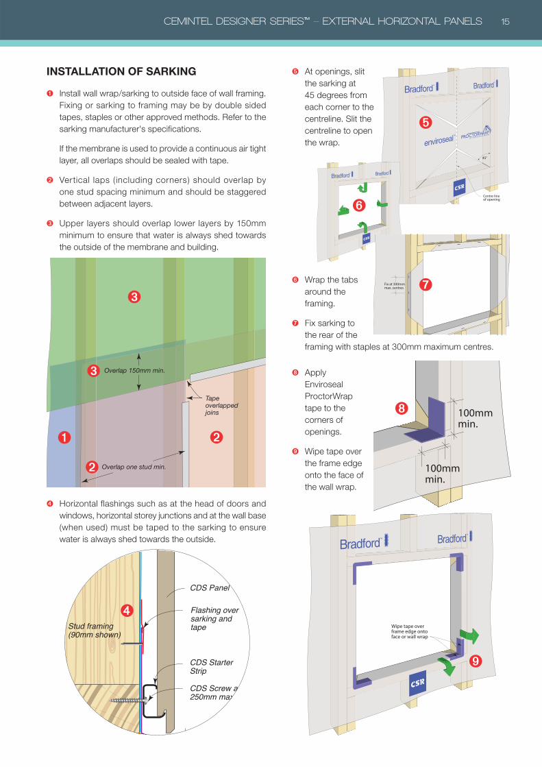
➑ Apply
Enviroseal
ProctorWrap
tape to the
corners of
openings.
➒ Wipe tape over
the frame edge
onto the face of
the wall wrap.
➎ At openings, slit
the sarking at
45 degrees from
each corner to the
centreline. Slit the
centreline to open
the wrap.
➏ Wrap the tabs
around the
framing.
➐ Fix sarking to
the rear of the
framing with staples at 300mm maximum centres.
➊ Install wall wrap/sarking to outside face of wall framing.
Fixing or sarking to framing may be by double sided
tapes, staples or other approved methods. Refer to the
sarking manufacturer's specifications.
If the membrane is used to provide a continuous air tight
layer, all overlaps should be sealed with tape.
➋ Vertical laps (including corners) should overlap by
one stud spacing minimum and should be staggered
between adjacent layers.
➌ Upper layers should overlap lower layers by 150mm
minimum to ensure that water is always shed towards
the outside of the membrane and building.
➍ Horizontal flashings such as at the head of doors and
windows, horizontal storey junctions and at the wall base
(when used) must be taped to the sarking to ensure
water is always shed towards the outside.
Overlap 150mm min.
Tape overlapped joins
Overlap one stud min.
INSTALLATION OF SARKING
45°
Centre line of opening
Fix at 300mm max. centres
100mm min.
100mm min.
Wipe tape over frame edge onto face or wall wrap
CDS Panel
Stud framing (90mm shown)
CDS Starter Strip
CDS Screw at 250mm max. cts
Flashing over sarking and tape
➍
➊
➋
➋
➌
➌
➎
➏
➐
➑
➒
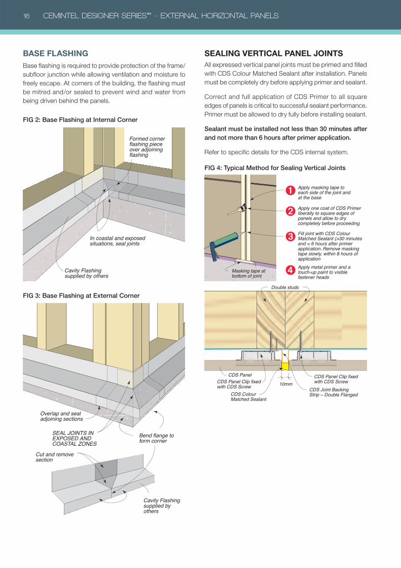
16 CEMINTEL DESIGNER SERIES™ – EXTERNAL HORIZONTAL PANELS
SEALING VERTICAL PANEL JOINTSAll expressed vertical panel joints must be primed and filled
with CDS Colour Matched Sealant after installation. Panels
must be completely dry before applying primer and sealant.
Correct and full application of CDS Primer to all square
edges of panels is critical to successful sealant performance.
Primer must be allowed to dry fully before installing sealant.
Sealant must be installed not less than 30 minutes after and not more than 6 hours after primer application.
Refer to specific details for the CDS internal system.
CDS Panel
10mmCDS Joint Backing Strip – Double FlangedCDS Colour
Matched Sealant
CDS Panel Clip fixed with CDS Screw
CDS Panel Clip fixed with CDS Screw
Double studs
Apply one coat of CDS Primer liberally to square edges of panels and allow to dry completely before proceeding
➋
Fill joint with CDS Colour Matched Sealant (>30 minutes and < 6 hours after primer application. Remove masking tape slowly, within 8 hours of application
➌
Apply masking tape to each side of the joint and at the base
Masking tape at bottom of joint
➊
Apply metal primer and a touch-up paint to visible fastener heads
➍
Cut and remove section
Bend flange to form corner
Overlap and seal adjoining sections
SEAL JOINTS IN EXPOSED AND COASTAL ZONES
Cavity Flashing supplied by others
In coastal and exposed situations, seal joints
Cavity Flashing supplied by others
Formed corner flashing piece over adjoining flashing
BASE FLASHINGBase flashing is required to provide protection of the frame/
subfloor junction while allowing ventilation and moisture to
freely escape. At corners of the building, the flashing must
be mitred and/or sealed to prevent wind and water from
being driven behind the panels.
FIG 2: Base Flashing at Internal Corner
FIG 3: Base Flashing at External Corner
FIG 4: Typical Method for Sealing Vertical Joints
CEMINTEL DESIGNER SERIES™ – EXTERNAL HORIZONTAL PANELS 17
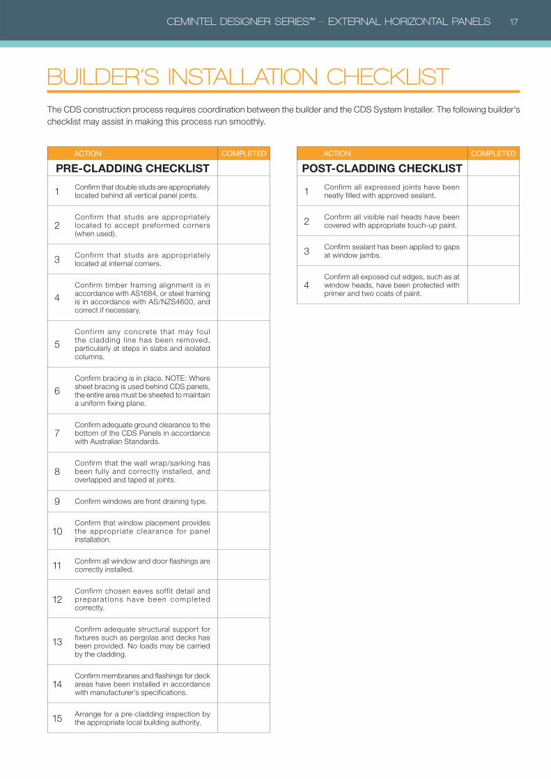
BUILDER’S INSTALLATION CHECKLIST The CDS construction process requires coordination between the builder and the CDS System Installer. The following builder's
checklist may assist in making this process run smoothly.
ACTION COMPLETED
PRE-CLADDING CHECKLIST
1Confirm that double studs are appropriately located behind all vertical panel joints.
2Confirm that studs are appropriately located to accept preformed corners (when used).
3Confirm that studs are appropriately located at internal corners.
4
Confirm timber framing alignment is in accordance with AS1684, or steel framing is in accordance with AS/NZS4600, and correct if necessary.
5
Conf irm any concrete that may foul the cladding l ine has been removed, particularly at steps in slabs and isolated columns.
6
Confirm bracing is in place. NOTE: Where sheet bracing is used behind CDS panels, the entire area must be sheeted to maintain a uniform fixing plane.
7Confirm adequate ground clearance to the bottom of the CDS Panels in accordance with Australian Standards.
8Confirm that the wall wrap/sarking has been fully and correctly installed, and overlapped and taped at joints.
9 Confirm windows are front draining type.
10Confirm that window placement provides the appropr iate clearance for panel installation.
11Confirm all window and door flashings are correctly installed.
12Confirm chosen eaves soffit detail and preparat ions have been completed correctly.
13
Confirm adequate structural support for fixtures such as pergolas and decks has been provided. No loads may be carried by the cladding.
14Confirm membranes and flashings for deck areas have been installed in accordance with manufacturer’s specifications.
15Arrange for a pre-cladding inspection by the appropriate local building authority.
ACTION COMPLETED
POST-CLADDING CHECKLIST
1Confirm all expressed joints have been neatly filled with approved sealant.
2Confirm all visible nail heads have been covered with appropriate touch-up paint.
3Confirm sealant has been applied to gaps at window jambs.
4Confirm all exposed cut edges, such as at window heads, have been protected with primer and two coats of paint.
18 CEMINTEL DESIGNER SERIES™ – EXTERNAL HORIZONTAL PANELS
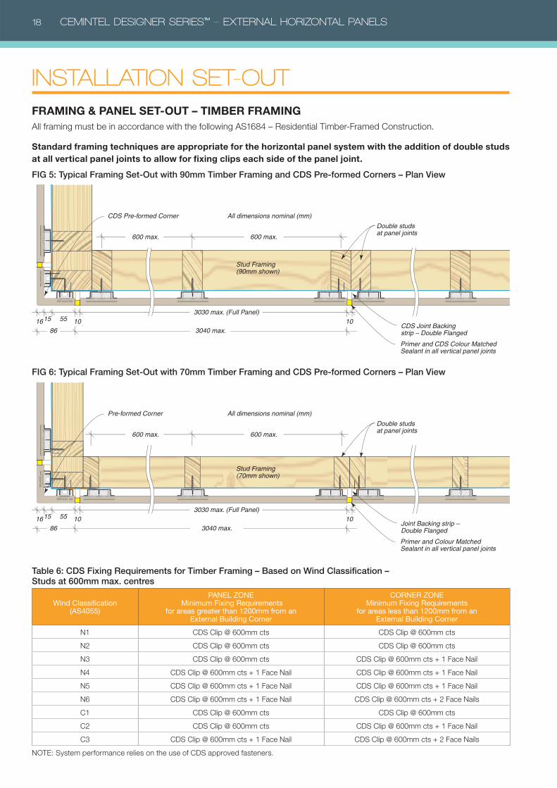
INSTALLATION SET-OUTFRAMING & PANEL SET-OUT – TIMBER FRAMINGAll framing must be in accordance with the following AS1684 – Residential Timber-Framed Construction.
Standard framing techniques are appropriate for the horizontal panel system with the addition of double studs at all vertical panel joints to allow for fixing clips each side of the panel joint.
Double studs at panel joints
Stud Framing (90mm shown)
CDS Pre-formed Corner
CDS Joint Backing strip – Double Flanged
Primer and CDS Colour Matched Sealant in all vertical panel joints
600 max. 600 max.
1516 10553030 max. (Full Panel)
8610
3040 max.
All dimensions nominal (mm)
Double studs at panel joints
Stud Framing (70mm shown)
Pre-formed Corner
Joint Backing strip – Double Flanged
Primer and Colour Matched Sealant in all vertical panel joints
600 max. 600 max.
1516 10553030 max. (Full Panel)
3040 max. 8610
All dimensions nominal (mm)
FIG 5: Typical Framing Set-Out with 90mm Timber Framing and CDS Pre-formed Corners – Plan View
FIG 6: Typical Framing Set-Out with 70mm Timber Framing and CDS Pre-formed Corners – Plan View
Table 6: CDS Fixing Requirements for Timber Framing – Based on Wind Classification – Studs at 600mm max. centres
Wind Classification(AS4055)
PANEL ZONE Minimum Fixing Requirements
for areas greater than 1200mm from an External Building Corner
CORNER ZONEMinimum Fixing Requirements
for areas less than 1200mm from an External Building Corner
N1 CDS Clip @ 600mm cts CDS Clip @ 600mm cts
N2 CDS Clip @ 600mm cts CDS Clip @ 600mm cts
N3 CDS Clip @ 600mm cts CDS Clip @ 600mm cts + 1 Face Nail
N4 CDS Clip @ 600mm cts + 1 Face Nail CDS Clip @ 600mm cts + 1 Face Nail
N5 CDS Clip @ 600mm cts + 1 Face Nail CDS Clip @ 600mm cts + 1 Face Nail
N6 CDS Clip @ 600mm cts + 1 Face Nail CDS Clip @ 600mm cts + 2 Face Nails
C1 CDS Clip @ 600mm cts CDS Clip @ 600mm cts
C2 CDS Clip @ 600mm cts CDS Clip @ 600mm cts + 1 Face Nail
C3 CDS Clip @ 600mm cts + 1 Face Nail CDS Clip @ 600mm cts + 2 Face Nails
NOTE: System performance relies on the use of CDS approved fasteners.
CEMINTEL DESIGNER SERIES™ – EXTERNAL HORIZONTAL PANELS 19
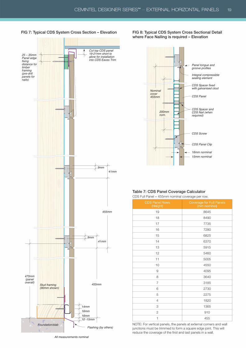
FIG 7: Typical CDS System Cross Section – Elevation
CDS Panel
Integral compressible sealing element
CDS Spacer and CDS Nail (when required)
CDS Spacer fixed with galvanised clout
CDS Panel Clip
Panel tongue and groove profiles
Nominal cover 455mm
200mm nom.
CDS Screw
16mm norminal 15mm norminal
Stud framing (90mm shown)
All measurements nominal
Flashing (by others)
10 -15mm16mm16mm
455mm
470mm(paneloverall)
14mm
9mm41mm
455mm
41mm
Foundation/slab
Cut top CDS panel 19-21mm short to allow for installation into CDS Eaves Trim
25 – 35mm Panel edge fixing distance for timber framing (pre-drill panels for nails)
9mm
FIG 8: Typical CDS System Cross Sectional Detail where Face Nailing is required – Elevation
Table 7: CDS Panel Coverage CalculatorCDS Full Panel = 455mm nominal coverage per row.
CDS Panel Rows(Height)
Coverage for Full Panels(mm nominal)
19 8645
18 8490
17 7735
16 7280
15 6825
14 6370
13 5915
12 5460
11 5005
10 4550
9 4095
8 3640
7 3185
6 2730
5 2275
4 1820
3 1365
2 910
1 455
NOTE: For vertical panels, the panels at external corners and wall
junctions must be trimmed to form a square edge joint. This will
reduce the coverage of the first and last panels in a wall.
20 CEMINTEL DESIGNER SERIES™ – EXTERNAL HORIZONTAL PANELS
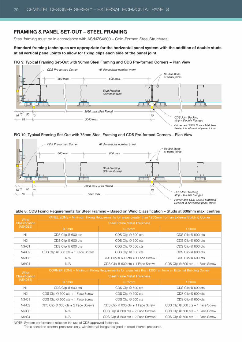
FRAMING & PANEL SET-OUT – STEEL FRAMINGSteel framing must be in accordance with AS/NZS4600 – Cold-Formed Steel Structures.
Standard framing techniques are appropriate for the horizontal panel system with the addition of double studs at all vertical panel joints to allow for fixing clips each side of the panel joint.
Double studs at panel joints
Stud Framing (90mm shown)
CDS Pre-formed Corner
CDS Joint Backing strip – Double Flanged
Primer and CDS Colour Matched Sealant in all vertical panel joints
600 max. 600 max.
1516 10553030 max. (Full Panel)
8610
3040 max.
All dimensions nominal (mm)
Double studs at panel joints
Stud Framing (75mm shown)
CDS Pre-formed Corner
CDS Joint Backing strip – Double Flanged
Primer and CDS Colour Matched Sealant in all vertical panel joints
600 max. 600 max.
1516 10553030 max. (Full Panel)
3040 max. 8610
All dimensions nominal (mm)
FIG 9: Typical Framing Set-Out with 90mm Steel Framing and CDS Pre-formed Corners – Plan View
FIG 10: Typical Framing Set-Out with 75mm Steel Framing and CDS Pre-formed Corners – Plan View
Table 8: CDS Fixing Requirements for Steel Framing – Based on Wind Classification – Studs at 600mm max. centres
Wind Classification
(AS4055)
PANEL ZONE – Minimum Fixing Requirements for areas greater than 1200mm from an External Building Corner
Steel Frame Metal Thickness
0.5mm 0.75mm 1.2mm
N1 CDS Clip @ 600 cts CDS Clip @ 600 cts CDS Clip @ 600 cts
N2 CDS Clip @ 600 cts CDS Clip @ 600 cts CDS Clip @ 600 cts
N3/C1 CDS Clip @ 600 cts CDS Clip @ 600 cts CDS Clip @ 600 cts
N4/C2 CDS Clip @ 600 cts + 1 Face Screw CDS Clip @ 600 cts CDS Clip @ 600 cts
N5/C3 N/A CDS Clip @ 600 cts + 1 Face Screw CDS Clip @ 600 cts
N6/C4 N/A CDS Clip @ 600 cts + 1 Face Screw CDS Clip @ 600 cts + 1 Face Screw
Wind Classification
(AS4055)
CORNER ZONE – Minimum Fixing Requirements for areas less than 1200mm from an External Building Corner
Steel Frame Metal Thickness
0.5mm 0.75mm 1.2mm
N1 CDS Clip @ 600 cts CDS Clip @ 600 cts CDS Clip @ 600 cts
N2 CDS Clip @ 600 cts + 1 Face Screw CDS Clip @ 600 cts CDS Clip @ 600 cts
N3/C1 CDS Clip @ 600 cts + 1 Face Screw CDS Clip @ 600 cts CDS Clip @ 600 cts
N4/C2 CDS Clip @ 600 cts + 2 Face Screws CDS Clip @ 600 cts + 1 Face Screw CDS Clip @ 600 cts + 1 Face Screw
N5/C3 N/A CDS Clip @ 600 cts + 2 Face Screws CDS Clip @ 600 cts + 1 Face Screw
N6/C4 N/A CDS Clip @ 600 cts + 2 Face Screws CDS Clip @ 600 cts + 1 Face Screw
NOTE: System performance relies on the use of CDS approved fasteners.
Table based on external pressures only, with internal linings designed to resist internal pressures.

CEMINTEL DESIGNER SERIES™ – EXTERNAL HORIZONTAL PANELS 21
FIG 11: Typical CDS System Cross Section – Elevation
CDS Panel
16mm norminal
Integral compressible sealing element
CDS Spacer and CDS Screw (when required)
CDS Spacer fixed with button head screw
CDS Panel Clip
Panel tongue and groove profiles
Nominal cover 455mm
200mm nom.
CDS Screw
15mm norminal
Stud framing (90mm shown)
All measurements nominal
Flashing (by others)
10 -15mm16mm16mm
455mm
470mm(paneloverall)
14mm
9mm41mm
455mm
41mm
Foundation/slab
Cut top CDS panel 19-21mm short to allow for installation into CDS Eaves Trim
9mm
30 – 40mm Panel edge fixing distance for steel framing
FIG 12: Typical CDS System Cross Sectional Detail where Face Fixing is required – Elevation
Table 9: CDS Panel Coverage CalculatorCDS Full Panel = 455mm nominal coverage per row.
CDS Panel Rows(Height)
Coverage for Full Panels(mm nominal)
19 8645
18 8490
17 7735
16 7280
15 6825
14 6370
13 5915
12 5460
11 5005
10 4550
9 4095
8 3640
7 3185
6 2730
5 2275
4 1820
3 1365
2 910
1 455
NOTE: For vertical panels, the panels at external corners and wall
junctions must be trimmed to form a square edge joint. This will
reduce the coverage of the first and last panels in a wall.
22 CEMINTEL DESIGNER SERIES™ – EXTERNAL HORIZONTAL PANELS
1213
14
1515
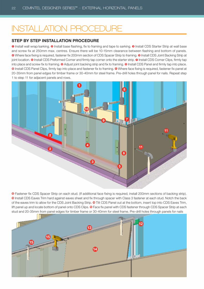
INSTALLATION PROCEDURESTEP BY STEP INSTALLATION PROCEDURE➊ Install wall wrap/sarking. ➋ Install base flashing, fix to framing and tape to sarking. ➌ Install CDS Starter Strip at wall base
and screw fix at 250mm max. centres. Ensure there will be 10-15mm clearance between flashing and bottom of panels.
➍ Where face fixing is required, fastener fix 200mm section of CDS Spacer Strip to framing. ➎ Install CDS Joint Backing Strip at
joint location. ➏ Install CDS Preformed Corner and firmly tap corner onto the starter strip. ➐ Install CDS Corner Clips, firmly tap
into place and screw fix to framing. ➑ Adjust joint backing strip and fix to framing. ➒ Install CDS Panel and firmly tap into place.
➓ Install CDS Panel Clips, firmly tap into place and fastener fix to framing. Where face fixing is required, fastener fix panel at
20-35mm from panel edges for timber frame or 30-40mm for steel frame. Pre-drill holes through panel for nails. Repeat step
1 to step 11 for adjacent panels and rows.
1
2
2
3
4
5
6
7
8
9
11
11
10
Fastener fix CDS Spacer Strip on each stud. (If additional face fixing is required, install 200mm sections of backing strip).
Install CDS Eaves Trim hard against eaves sheet and fix through spacer with Class 3 fastener at each stud. Notch the back
of the eaves trim to allow for the CDS Joint Backing Strip. Tilt CDS Panel out at the bottom, insert top into CDS Eaves Trim,
lift panel up and locate bottom of panel onto CDS Clips. Face fix panel with CDS fastener through CDS Spacer Strip at each
stud and 20-35mm from panel edges for timber frame or 30-40mm for steel frame. Pre-drill holes through panels for nails
CEMINTEL DESIGNER SERIES™ – EXTERNAL HORIZONTAL PANELS 23
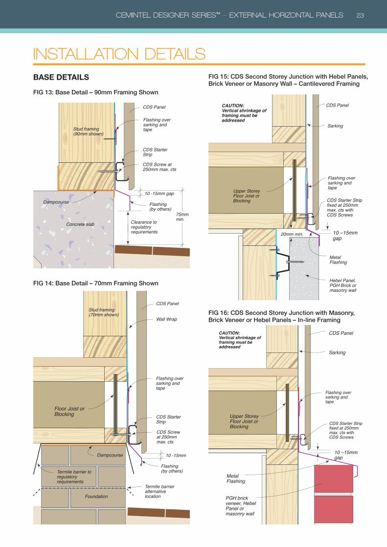
CDS Panel
Stud framing (90mm shown)
CDS Starter Strip
CDS Screw at 250mm max. cts
Flashing (by others)
Clearance to regulatory requirements
10 -15mm gap
Dampcourse
Concrete slab
75mm min.
Flashing over sarking and tape
CDS PanelStud framing (70mm shown)
Wall Wrap
CDS Starter Strip
Flashing (by others)
10 -15mm
Foundation
Dampcourse
Floor Joist or Blocking
Termite barrier to regulatory requirements
Termite barrier alternative location
CDS Screw at 250mm max. cts
Flashing over sarking and tape
FIG 13: Base Detail – 90mm Framing Shown
BASE DETAILS
INSTALLATION DETAILS
FIG 14: Base Detail – 70mm Framing Shown
FIG 15: CDS Second Storey Junction with Hebel Panels, Brick Veneer or Masonry Wall – Cantilevered Framing
FIG 16: CDS Second Storey Junction with Masonry, Brick Veneer or Hebel Panels – In-line Framing
CAUTION:Vertical shrinkage of framing must be addressed
20mm min.
CDS Panel
Metal Flashing
Hebel Panel, PGH Brick or masonry wall
Sarking
Upper Storey Floor Joist or Blocking CDS Starter Strip
fixed at 250mm max. cts with CDS Screws
10 –15mm gap
Flashing over sarking and tape
10 –15mm gap
CDS Panel
Metal Flashing
PGH brick veneer, Hebel Panel or masonry wall
Sarking
Upper Storey Floor Joist or Blocking
CAUTION:Vertical shrinkage of framing must be addressed
CDS Starter Strip fixed at 250mm max. cts with CDS Screws
Flashing over sarking and tape

24 CEMINTEL DESIGNER SERIES™ – EXTERNAL HORIZONTAL PANELS
FIG 17: External Corner Detail – With Preformed Corner – Plan View
CORNER DETAILSAdditional studs may be required at corners to allow for
fixing CDS Panel Clips and other components.
CDS Panel10mm
CDS Backing Strip –�Double Flanged
CDS Colour Matched Sealant
CDS Panel Clip fixed with CDS Screw
CDS Preformed External Corner
CDS Corner Clip fixed with CDS Screw
Stud framing
CDS Panel CDS Nails at 600mm max. cts
CDS Nails at 600mm max. cts
CDS Panel Clip
CDS Coloured External Corner Trim
CDS Spacer Strip
CDS Screw
Stud framing
FIG 18: External Corner Detail – With Coloured External Corner Trim – Plan View
CDS Panel
10mm
CDS Panel Clip fixed with CDS Screw
CDS Colour Matched Sealant
CDS Internal Corner Backing
CDS Backing Strip – Single Flange
Stud framing
56mm min.
Additional Stud for clip fixing
FIG 19: Internal Corner Detail – With Backing Strip and Colour Matched Sealant – Plan View
CDS Panel
CDS Colour Matched Sealant
Bond breaker tape
Metal flashing (by others)
CDS Spacer StripStud framing
Stud framing
Blocking to suit
CDS Spacer and Nails at top, bottom and mid height of each panel with touch-up paint on heads
20-35mm timber frame30-40mm steel frame
FIG 20: Obtuse Angle Corner Detail – With Metal Flashing and Colour Matched Sealant – Plan View
CEMINTEL DESIGNER SERIES™ – EXTERNAL HORIZONTAL PANELS 25
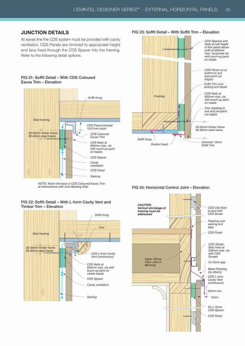
JUNCTION DETAILSAt eaves line the CDS system must be provided with cavity
ventilation. CDS Panels are trimmed to appropriate height
and face fixed through the CDS Spacer into the framing.
Refer to the following detail options.
CDS Panel
Stud framing
20-35mm timber frame30-40mm steel frame
Sarking
CDS Nails at 600mm max. cts with touch-up paint on heads
Cavity ventilation
CDS Coloured Eaves Trim
NOTE: Notch the back of CDS Coloured Eaves Trim at intersections with Joint Backing Strip
CDS Panel trimmed 19-21mm short
CDS Spacer
Soffit lining
FIG 21: Soffit Detail – With CDS Coloured Eaves Trim – Elevation
Stud framing
Sarking
Cavity ventilation
Trim
CDS Spacer
Soffit lining
CDS Nails at 600mm max. cts with touch-up paint on visible heads
20-35mm timber frame30-40mm steel frame
CDS L-form Cavity Vent (continuous)
FIG 22: Soffit Detail – With L-form Cavity Vent and Timber Trim – Elevation
CDS Panel cut at bottom to suit (pre-paint cut edges)
Framing
Soffit lining
CDS Nails at 600mm max. cts with touch-up paint on heads
CDS Spacers and Nails at half height of first panel above soffit at 600mm max. horizontal cts with touch-up paint on heads
20-35mm timber frame30-40mm steel frame
Trim cladding to suit and pre-paint cut edges
Soffit Trim over sarking and taped
Cemintel 15mm Soffit Trim Sealant bead
FIG 23: Soffit Detail – With Soffit Trim – Elevation
Upper Storey Floor Joist or Blocking
CDS Starter Strip fixed at 250mm max. cts with CDS Screws
CDS Panel
10-15mm gap
20mm min.
12mm
CDS Panel
CDS Clip fixed to stud with CDS Screw
50 x 15mm CDS Spacer
Metal Flashing(by others)CDS L-form Cavity Vent (continuous)
CAUTION:Vertical shrinkage of framing must be addressed
Flashing over sarking and tape
FIG 24: Horizontal Control Joint – Elevation
26 CEMINTEL DESIGNER SERIES™ – EXTERNAL HORIZONTAL PANELS
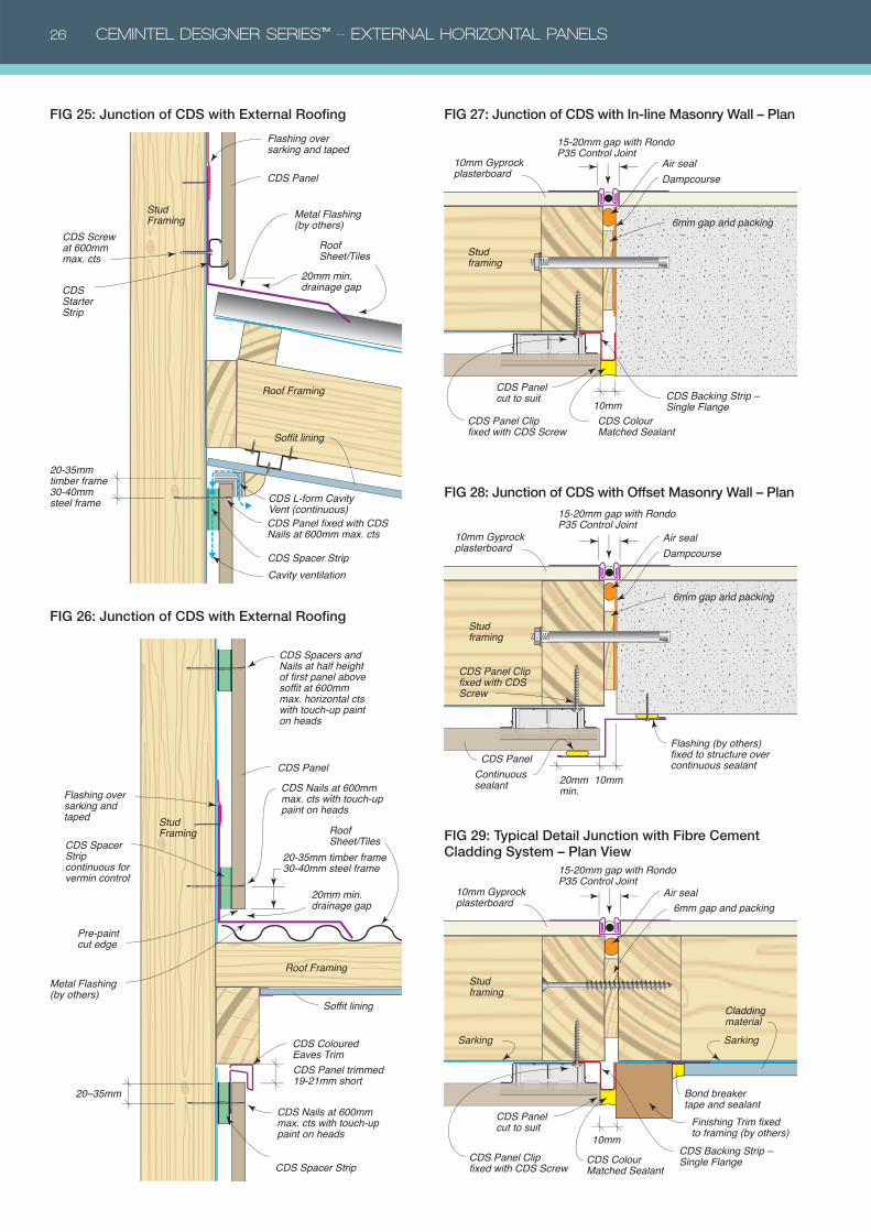
Flashing over sarking and taped
Stud Framing
Roof Framing
Soffit lining
CDS Starter Strip
CDS Spacer Strip
Roof Sheet/Tiles
Metal Flashing(by others)
20mm min. drainage gap
CDS Panel
CDS Panel fixed with CDS Nails at 600mm max. cts
CDS Screw at 600mm max. cts
CDS L-form Cavity Vent (continuous)
20-35mm timber frame30-40mm steel frame
Cavity ventilation
Stud Framing
Roof Framing
CDS Spacer Strip continuous for vermin control
Metal Flashing (by others)
Pre-paint cut edge
CDS Spacer Strip
CDS Panel
Roof Sheet/Tiles
20mm min. drainage gap
CDS Panel trimmed 19-21mm short
CDS Coloured Eaves Trim
20–35mm
Soffit lining
CDS Nails at 600mm max. cts with touch-up paint on heads
CDS Nails at 600mm max. cts with touch-up paint on heads
Flashing over sarking and taped
CDS Spacers and Nails at half height of first panel above soffit at 600mm max. horizontal cts with touch-up paint on heads
20-35mm timber frame30-40mm steel frame
FIG 25: Junction of CDS with External Roofing
FIG 26: Junction of CDS with External Roofing
CDS Panel cut to suit
10mmCDS Colour Matched Sealant
CDS Backing Strip – Single Flange
CDS Panel Clip fixed with CDS Screw
Dampcourse
6mm gap and packing
Air seal
15-20mm gap with Rondo P35 Control Joint
10mm Gyprock plasterboard
Stud framing
Dampcourse
6mm gap and packing
Air seal
CDS Panel
10mm20mm min.
Continuous sealant
Flashing (by others) fixed to structure over continuous sealant
CDS Panel Clip fixed with CDS Screw
15-20mm gap with Rondo P35 Control Joint
10mm Gyprock plasterboard
Stud framing
FIG 27: Junction of CDS with In-line Masonry Wall – Plan
FIG 28: Junction of CDS with Offset Masonry Wall – Plan
10mm
CDS Colour Matched Sealant
CDS Backing Strip – Single Flange
Cladding material
Finishing Trim fixed to framing (by others)
Bond breaker tape and sealant
Sarking Sarking
15-20mm gap with Rondo P35 Control Joint
10mm Gyprock plasterboard
Stud framing
CDS Panel cut to suit
CDS Panel Clip fixed with CDS Screw
6mm gap and packingAir seal
FIG 29: Typical Detail Junction with Fibre Cement Cladding System – Plan View
CEMINTEL DESIGNER SERIES™ – EXTERNAL HORIZONTAL PANELS 27
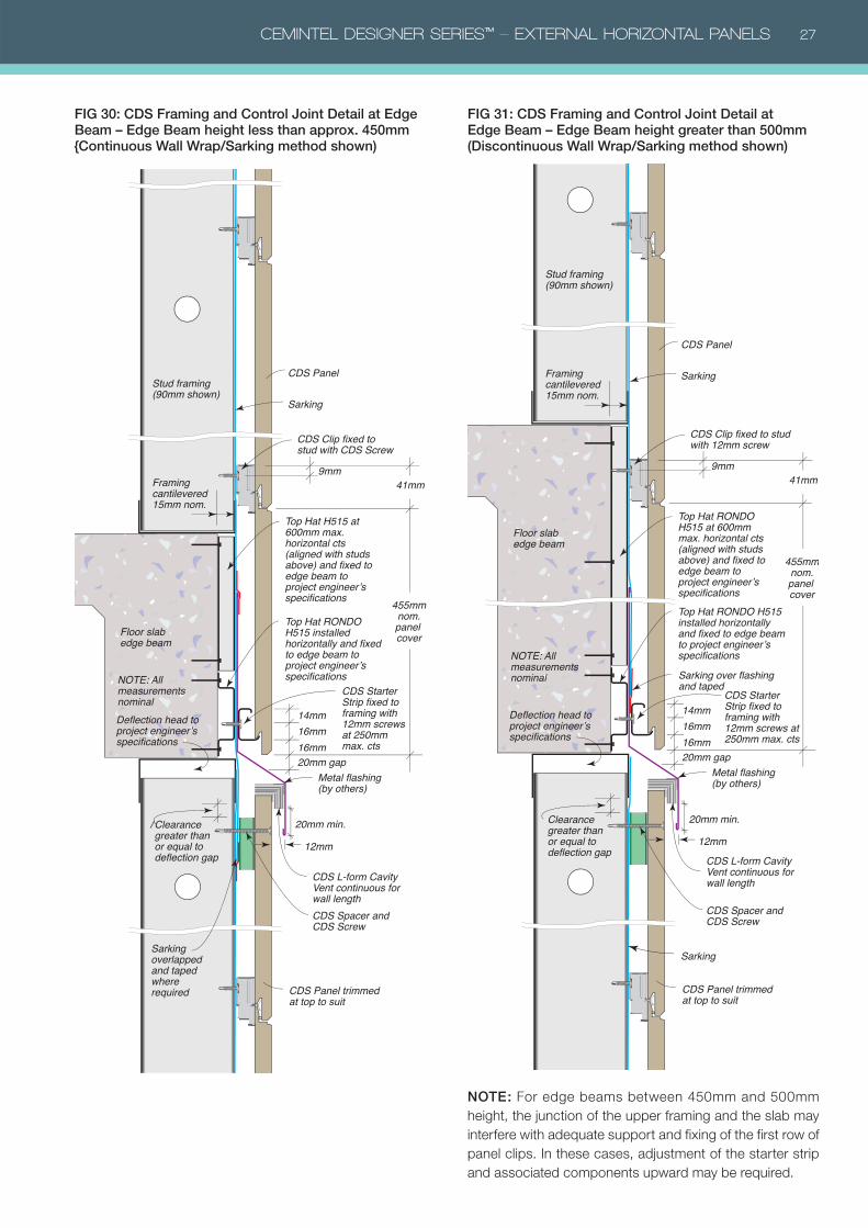
FIG 30: CDS Framing and Control Joint Detail at Edge Beam – Edge Beam height less than approx. 450mm {Continuous Wall Wrap/Sarking method shown)
Top Hat H515 at 600mm max. horizontal cts (aligned with studs above) and fixed to edge beam to project engineer’s specifications
CDS Spacer and CDS Screw
CDS L-form Cavity Vent continuous for wall length
Stud framing (90mm shown)
Framing cantilevered 15mm nom.
NOTE: All measurements nominalDeflection head to project engineer’s specifications
20mm gap16mm
Clearance greater thanor equal todeflection gap
16mm
455mmnom.panel cover
14mm
9mm41mm
Floor slab edge beam
CDS Clip fixed to stud with CDS Screw
Top Hat RONDO H515 installed horizontally and fixed to edge beam to project engineer’s specifications
CDS Starter Strip fixed to framing with 12mm screws at 250mm max. cts
CDS Panel
CDS Panel trimmed at top to suit
Sarking
Sarking overlapped and taped where required
Metal flashing (by others)
20mm min.
12mm
FIG 31: CDS Framing and Control Joint Detail at Edge Beam – Edge Beam height greater than 500mm (Discontinuous Wall Wrap/Sarking method shown)
CDS Panel
CDS Panel trimmed at top to suit
Sarking
Sarking
Sarking over flashing and taped
CDS Spacer and CDS Screw
CDS L-form Cavity Vent continuous for wall length
Stud framing (90mm shown)
Framing cantilevered 15mm nom.
NOTE: All measurements nominal
20mm gap16mm
Clearance greater thanor equal todeflection gap
16mm
455mmnom.panel cover
14mm
9mm41mm
Floor slab edge beam
Top Hat RONDO H515 at 600mm max. horizontal cts (aligned with studs above) and fixed to edge beam to project engineer’s specifications
CDS Clip fixed to stud with 12mm screw
Top Hat RONDO H515 installed horizontally and fixed to edge beam to project engineer’s specifications
CDS Starter Strip fixed to framing with 12mm screws at 250mm max. cts
Metal flashing (by others)
20mm min.
12mm
Deflection head to project engineer’s specifications
NOTE: For edge beams between 450mm and 500mm
height, the junction of the upper framing and the slab may
interfere with adequate support and fixing of the first row of
panel clips. In these cases, adjustment of the starter strip
and associated components upward may be required.
28 CEMINTEL DESIGNER SERIES™ – EXTERNAL HORIZONTAL PANELS
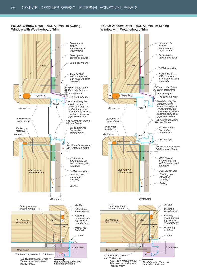
CDS Panel
Stud
A&L Weatherboard Reveal Trim reversed and sealant (special order)
100x19mm reveal shownFlashing recommended (by window manufacturer)
Sarking wrapped around corners
Packer (by installer)
Jamb
31mm nom.
CDS Panel Clip fixed with CDS Screw
Stud framing(90mm shown)
Air seal
Head Flashing 20mm min. past edge of window
CDS Spacer Strip
CDS Spacer StripLintel
31mm nom.
100x19mm reveal shown
Flashing over sarking (by installer)
Sarking
Sill weather flap (by window manufacturer)
A&L Aluminium Awning Window Frame
Packer (by installer)
Air seal
Air seal
No packing10-15mm gap
Head
Sill
Clearance to window manufacturer’s requirements
Stud framing (90mm shown)
Flashing over sarking and taped
Pre-paint cut edge
CDS Nails at 600mm max. cts with touch-up paint on heads
CDS Nails at 600mm max. cts with touch-up paint on heads
20-35mm timber frame30-40mm steel frame
20-35mm timber frame30-40mm steel frame
Metal Flashing (by installer) extend 20mm past edge of window frame, turn up stop-ends, slit side panels to suit and fill gaps with sealant
Air seal
CDS Panel
StudStud framing(90mm shown)
90x19mm reveal shownFlashing recommended (by window manufacturer)
Sarking wrapped around corners
Packer (by installer)
Jamb
31mm nom.
CDS Panel Clip fixed with CDS Screw
Sill drainage
A&L Weatherboard Reveal Trim reversed and sealant (special order)
Head Flashing 20mm min. past edge of window
Air seal
Air seal
Stud framing (90mm shown)
Lintel
31mm nom.
90x19mm reveal shown
Sarking
Sill weather flap (by window manufacturer)
A&L Aluminium Sliding Window Frame
Packer (by installer)
No packing
Head
Sill
CDS Spacer Strip
CDS Spacer Strip
Flashing over sarking (by installer)
CDS Nails at 600mm max. cts with touch-up paint on heads
CDS Nails at 600mm max. cts with touch-up paint on heads
20-35mm timber frame30-40mm steel frame
20-35mm timber frame30-40mm steel frame
10-15mm gapPre-paint cut edge
Clearance to window manufacturer’s requirementsFlashing over sarking and taped
Metal Flashing (by installer) extend 20mm past edge of window frame, turn up stop-ends, slit side panels to suit and fill gaps with sealant
FIG 32: Window Detail – A&L Aluminium Awning Window with Weatherboard Trim
FIG 33: Window Detail – A&L Aluminium Sliding Window with Weatherboard Trim
CEMINTEL DESIGNER SERIES™ – EXTERNAL HORIZONTAL PANELS 29
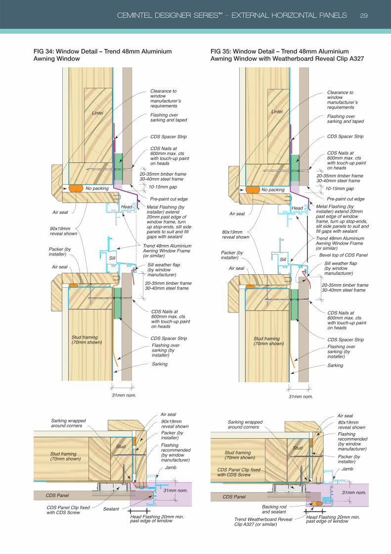
Air seal
CDS Panel
Backing rod and sealant
Stud
Trend Weatherboard Reveal Clip A327 (or similar)
80x19mm reveal shownFlashing recommended (by window manufacturer)
Sarking wrapped around corners
Packer (by installer)
JambCDS Panel Clip fixed with CDS Screw
31mm nom.
Stud framing (70mm shown)
Head Flashing 20mm min. past edge of window
Air seal
Clearance to window manufacturer’s requirementsFlashing over sarking and taped
Stud framing (70mm shown)
Lintel
Air seal
80x19mm reveal shown
Sarking
Sill weather flap (by window manufacturer)
Bevel top of CDS Panel
Trend 48mm Aluminium Awning Window Frame (or similar)
Packer (by installer)
No packing
Head
Sill
31mm nom.
CDS Spacer Strip
CDS Spacer Strip
Flashing over sarking (by installer)
CDS Nails at 600mm max. cts with touch-up paint on heads
CDS Nails at 600mm max. cts with touch-up paint on heads
20-35mm timber frame30-40mm steel frame
20-35mm timber frame30-40mm steel frame
10-15mm gap
Pre-paint cut edgeMetal Flashing (by installer) extend 20mm past edge of window frame, turn up stop-ends, slit side panels to suit and fill gaps with sealant
Air seal
CDS Panel
StudStud framing(70mm shown)
90x19mm reveal shown
Flashing recommended (by window manufacturer)
Sarking wrapped around corners
Packer (by installer)
Jamb
Sealant
31mm nom.
CDS Panel Clip fixed with CDS Screw
Head Flashing 20mm min. past edge of window
Air seal
Air seal
Clearance to window manufacturer’s requirementsFlashing over sarking and taped
Stud framing (70mm shown)
Lintel
31mm nom.
90x19mm reveal shown
Sarking
Sill weather flap (by window manufacturer)
Trend 48mm Aluminium Awning Window Frame (or similar)
Packer (by installer)
No packing
Head
Sill
CDS Spacer Strip
CDS Spacer Strip
Flashing over sarking (by installer)
CDS Nails at 600mm max. cts with touch-up paint on heads
CDS Nails at 600mm max. cts with touch-up paint on heads
20-35mm timber frame30-40mm steel frame
20-35mm timber frame30-40mm steel frame
10-15mm gap
Pre-paint cut edgeMetal Flashing (by installer) extend 20mm past edge of window frame, turn up stop-ends, slit side panels to suit and fill gaps with sealant
FIG 34: Window Detail – Trend 48mm Aluminium Awning Window
FIG 35: Window Detail – Trend 48mm Aluminium Awning Window with Weatherboard Reveal Clip A327
30 CEMINTEL DESIGNER SERIES™ – EXTERNAL HORIZONTAL PANELS
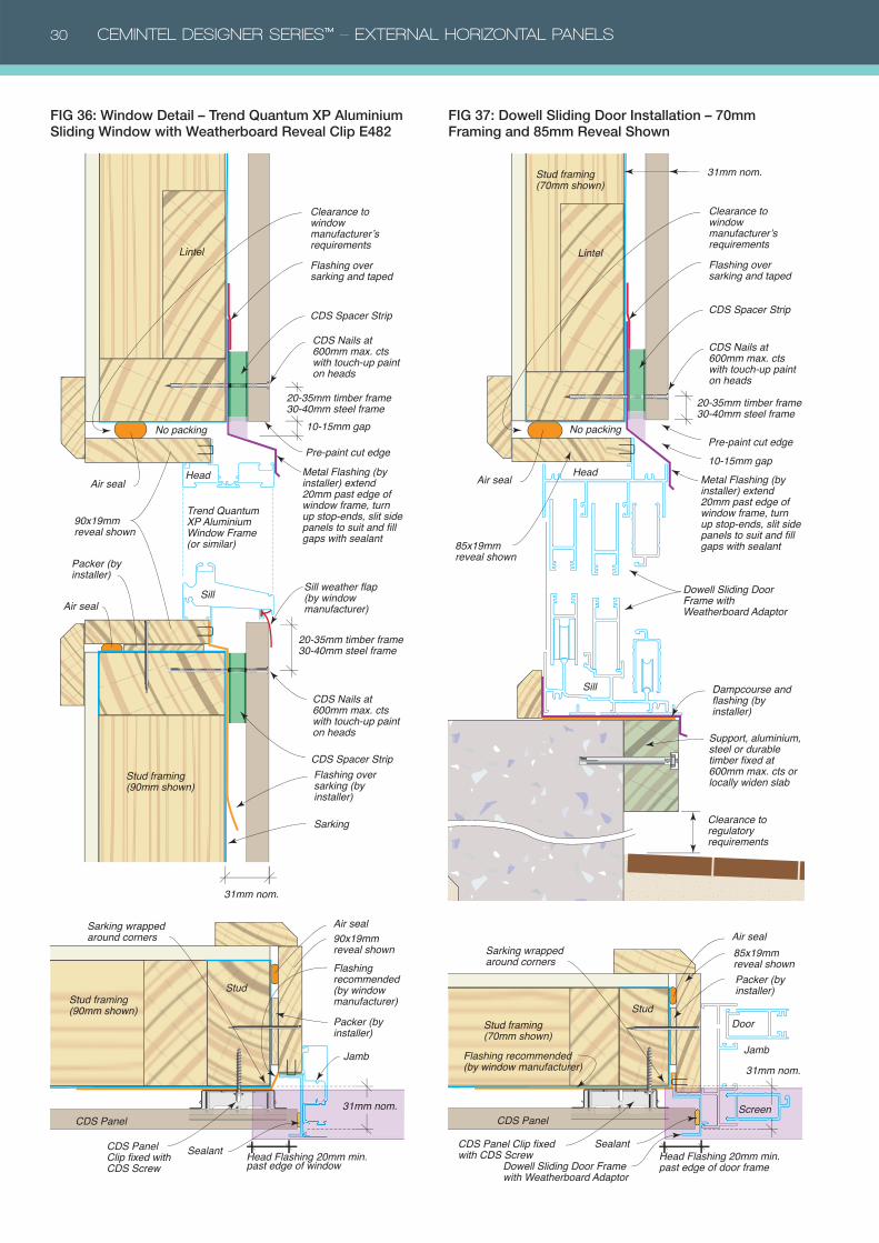
Air seal
CDS Panel
Sealant
Stud
90x19mm reveal shownFlashing recommended (by window manufacturer)
Sarking wrapped around corners
Packer (by installer)
Jamb
CDS Panel Clip fixed with CDS Screw
31mm nom.
Stud framing(90mm shown)
Head Flashing 20mm min. past edge of window
Air seal
Air seal
Clearance to window manufacturer’s requirementsFlashing over sarking and taped
Lintel
90x19mm reveal shown
Sarking
Trend Quantum XP Aluminium Window Frame (or similar)
Packer (by installer)
No packing
Head
Sill
Stud framing (90mm shown)
Sill weather flap (by window manufacturer)
31mm nom.
CDS Spacer Strip
CDS Spacer Strip
Flashing over sarking (by installer)
CDS Nails at 600mm max. cts with touch-up paint on heads
CDS Nails at 600mm max. cts with touch-up paint on heads
20-35mm timber frame30-40mm steel frame
20-35mm timber frame30-40mm steel frame
10-15mm gap
Pre-paint cut edgeMetal Flashing (by installer) extend 20mm past edge of window frame, turn up stop-ends, slit side panels to suit and fill gaps with sealant
Air seal
CDS Panel
Sealant
Stud
Dowell Sliding Door Frame with Weatherboard Adaptor
Stud framing(70mm shown)
85x19mm reveal shown
Flashing recommended (by window manufacturer)
Sarking wrapped around corners
Packer (by installer)
Jamb
Door
Screen
31mm nom.
CDS Panel Clip fixed with CDS Screw Head Flashing 20mm min.
past edge of door frame
Air seal
Clearance to window manufacturer’s requirementsFlashing over sarking and taped
Lintel
31mm nom.
85x19mm reveal shown
Dampcourse and flashing (by installer)
Support, aluminium, steel or durable timber fixed at 600mm max. cts or locally widen slab
Dowell Sliding Door Frame with Weatherboard Adaptor
No packing
Head
Sill
Clearance to regulatory requirements
Stud framing(70mm shown)
CDS Spacer Strip
Pre-paint cut edge
CDS Nails at 600mm max. cts with touch-up paint on heads
10-15mm gap
20-35mm timber frame30-40mm steel frame
Metal Flashing (by installer) extend 20mm past edge of window frame, turn up stop-ends, slit side panels to suit and fill gaps with sealant
FIG 36: Window Detail – Trend Quantum XP Aluminium Sliding Window with Weatherboard Reveal Clip E482
FIG 37: Dowell Sliding Door Installation – 70mm Framing and 85mm Reveal Shown
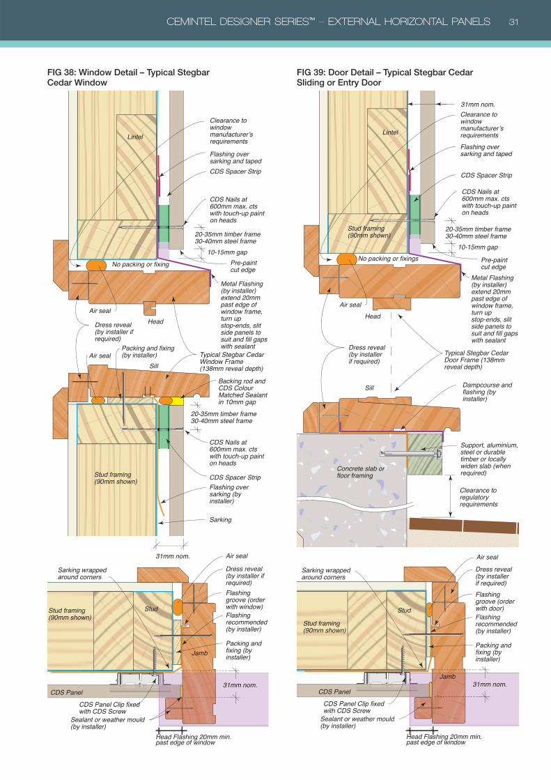
CEMINTEL DESIGNER SERIES™ – EXTERNAL HORIZONTAL PANELS 31
CDS Panel
Stud
Sealant or weather mould (by installer)
Flashing recommended (by installer)
Flashing groove (order with window)
Sarking wrapped around corners
Jamb
31mm nom.
CDS Panel Clip fixed with CDS Screw
Stud framing(90mm shown)
Packing and fixing (by installer)
Head Flashing 20mm min. past edge of window
CDS Spacer Strip
CDS Spacer Strip
Lintel
31mm nom.
Flashing over sarking (by installer)
Sarking
Typical Stegbar Cedar Window Frame (138mm reveal depth)
Packing and fixing (by installer)
Dress reveal (by installer if required)
Dress reveal (by installer if required)
Air seal
No packing or fixing
Head
Sill
Stud framing (90mm shown)
Backing rod and CDS Colour Matched Sealant in 10mm gap
CDS Nails at 600mm max. cts with touch-up paint on heads
20-35mm timber frame30-40mm steel frame
CDS Nails at 600mm max. cts with touch-up paint on heads
20-35mm timber frame30-40mm steel frame
10-15mm gapPre-paint cut edge
Air seal
Air seal
Clearance to window manufacturer’s requirementsFlashing over sarking and taped
Metal Flashing (by installer) extend 20mm past edge of window frame, turn up stop-ends, slit side panels to suit and fill gaps with sealant
CDS Panel
Stud
Stud framing(90mm shown)
Sarking wrapped around corners
Sealant or weather mould (by installer)
Flashing recommended (by installer)
Flashing groove (order with door)
Jamb31mm nom.
CDS Panel Clip fixed with CDS Screw
Packing and fixing (by installer)
Head Flashing 20mm min. past edge of window
Air seal
Air seal
Clearance to window manufacturer’s requirementsFlashing over sarking and taped
Lintel
31mm nom.
Dampcourse and flashing (by installer)
Concrete slab or floor framing
Support, aluminium, steel or durable timber or locally widen slab (when required)
Typical Stegbar Cedar Door Frame (138mm reveal depth)
No packing or fixings
Head
Sill
Clearance to regulatory requirements
Stud framing(90mm shown)
CDS Spacer Strip
Dress reveal (by installer if required)
Dress reveal (by installer if required)
CDS Nails at 600mm max. cts with touch-up paint on heads
20-35mm timber frame30-40mm steel frame
10-15mm gap
Pre-paint cut edge
Metal Flashing (by installer) extend 20mm past edge of window frame, turn up stop-ends, slit side panels to suit and fill gaps with sealant
FIG 38: Window Detail – Typical Stegbar Cedar Window
FIG 39: Door Detail – Typical Stegbar Cedar Sliding or Entry Door
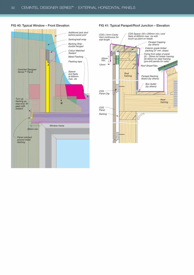
32 CEMINTEL DESIGNER SERIES™ – EXTERNAL HORIZONTAL PANELS
Flashing tape
Metal Flashing
Turn up flashing as stop-end, fill gaps with sealant
Window frame
Panel notched around metal flashing
20mm min.
Spacer and Nails at 600mm max. cts
Backing Strip - double flanged
Additional jack stud behind panel jointSarking/wall wrap
Cemintel Designer Series™ Panel
Colour Matched Sealant
CDS Spacer (50 x 200mm min.) and Nails at 600mm max. cts with touch-up paint on heads
CDS Panel
CDS L-form Cavity Vent continuous for wall length
Parapet Capping (by others)
Exterior grade timber packing (5° min. slope)
Parapet Backing Board (by others)
CDS Panel Clip
Stud framing
Roof framing
Roof Sheet/Tiles
Box Gutter (by others)
Sarking
20mm min.
12mm
Fixing from edge of panel 25 – 35mm for timber framing 30-40mm for steel framing (pre-drill panels for nails)
FIG 40: Typical Window – Front Elevation FIG 41: Typical Parapet/Roof Junction – Elevation
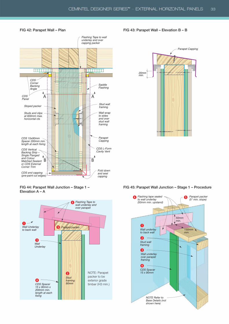
CEMINTEL DESIGNER SERIES™ – EXTERNAL HORIZONTAL PANELS 33
CDS Panel
Sloped packer
Studs and clips at 600mm max. horizontal cts
Wall wrap to sides and over stud wall framing
CDS Vertical Backing Strip –�Single Flanged and Colour Matched Sealant or CDS External Corner Trim
Flashing Tape to wall underlay and over capping packer
Saddle Flashing
Parapet Capping
Stud wall framing
CDS L-Form Cavity Vent
CDS end capping (pre-paint cut edges)
Fold down and seal capping
CDS 15x90mm Spacer 200mm min. length at each fixing
CDS Corner Backing Angle
AA
BB
FIG 42: Parapet Wall – Plan
20mm min.
Parapet Capping
FIG 43: Parapet Wall – Elevation B – B
FIG 44: Parapet Wall Junction – Stage 1 – Elevation A – A
FIG 45: Parapet Wall Junction – Stage 1 – Procedure
Parapet packer (5° min. slope)
Flashing tape sealed to wall underlay (50mm min. upstand)
Wall underlay to back wall
NOTE Refer to Base Details (not shown here)
➊
Stud wall framing
➋
➌
➎ ➏
Wall underlay over parapet framing
130mm min.
50mm min.
CDS Spacer 15 x 90mm
➍
Flashing Tape to wall underlay and over parapet
Parapet packer Wall Underlay to back wall
Stud framing 90mm
Wall Underlay
CDS Spacer 15 x 90mm x 200mm min. length at each fixing
➊
➋
➌
➍
➎
➏
NOTE: Parapet
packer to be
exterior grade
timber (H3 min.)
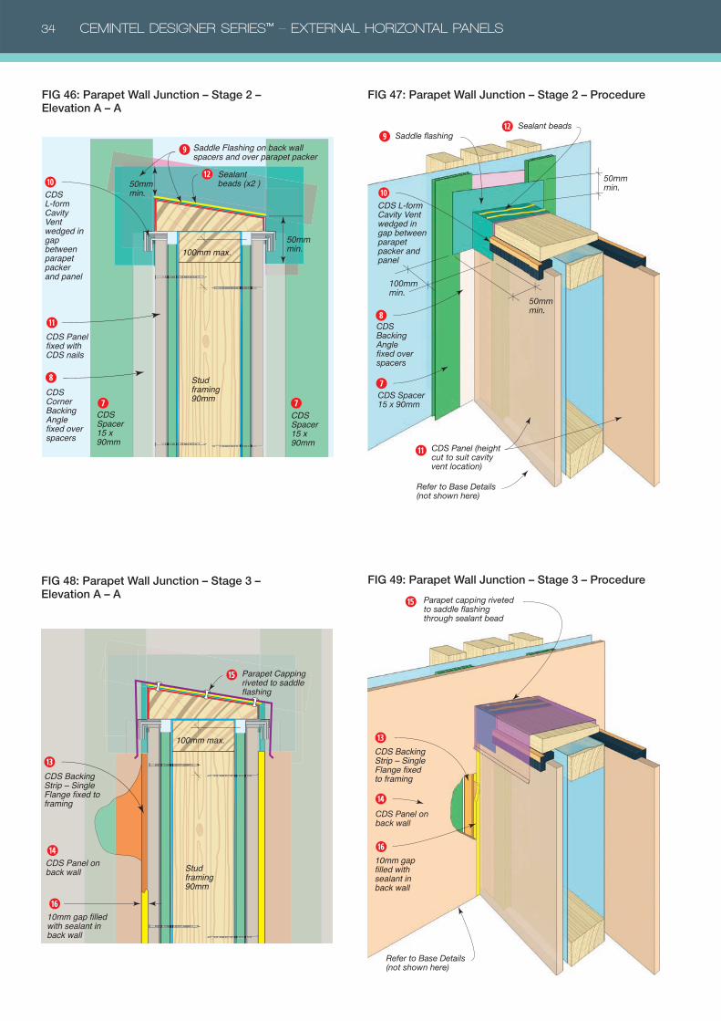
34 CEMINTEL DESIGNER SERIES™ – EXTERNAL HORIZONTAL PANELS
Parapet Capping riveted to saddle flashing
Stud framing 90mm
100mm max.
10mm gap filled with sealant in back wall
CDS Panel on back wall
CDS Backing Strip – Single Flange fixed to framing
⓭
⓮
⓰
⓯
FIG 48: Parapet Wall Junction – Stage 3 – Elevation A – A
FIG 49: Parapet Wall Junction – Stage 3 – Procedure
Parapet capping riveted to saddle flashing through sealant bead
CDS Panel on back wall
CDS Backing Strip – Single Flange fixed to framing
10mm gap filled with sealant in back wall
Refer to Base Details (not shown here)
⓭
⓮
⓯
⓰
Saddle Flashing on back wall spacers and over parapet packer
Stud framing 90mm
CDS Spacer 15 x 90mm
CDS Spacer 15 x 90mm
100mm max.
CDS Panel fixed with CDS nails
50mm min.
50mm min.
CDS Corner Backing Angle fixed over spacers
➐ ➐
➑
➒
➓
⓫
CDS L-form Cavity Vent wedged in gap between parapet packer and panel
Sealant beads (x2 )
⓬
FIG 46: Parapet Wall Junction – Stage 2 – Elevation A – A
FIG 47: Parapet Wall Junction – Stage 2 – Procedure
CDS Spacer 15 x 90mm
Saddle flashing
CDS Backing Angle fixed over spacers
CDS Panel (height cut to suit cavity vent location)
Refer to Base Details (not shown here)
50mm min.
50mm min.
100mm min.
➐
➑
➓
⓫
➒
Sealant beads⓬
CDS L-form Cavity Vent wedged in gap between parapet packer and panel
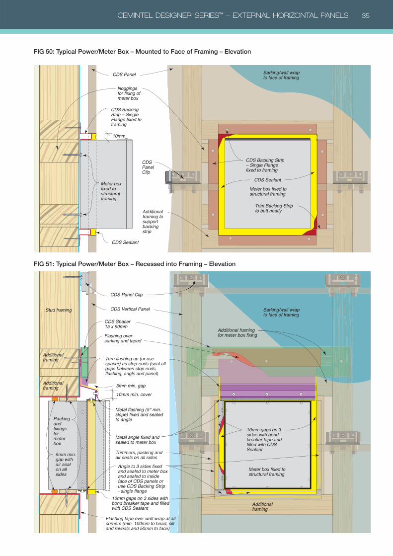
CEMINTEL DESIGNER SERIES™ – EXTERNAL HORIZONTAL PANELS 35
FIG 50: Typical Power/Meter Box – Mounted to Face of Framing – Elevation
FIG 51: Typical Power/Meter Box – Recessed into Framing – Elevation
Meter box fixed to structural framing
Meter box fixed to structural framing
Noggings for fixing of meter box
Additional framing to support backing strip
Trim Backing Strip to butt neatly
CDS Backing Strip – Single Flange fixed to framing
CDS Backing Strip – Single Flange fixed to framing
CDS Sealant
CDS Sealant
10mm
CDS Panel Clip
CDS Panel Sarking/wall wrap to face of framing
Packing and fixings for meter box
5mm min. gap with air seal on all sides
Additional framing for meter box fixing
Sarking/wall wrap to face of framing
Flashing tape over wall wrap at all corners (min. 100mm to head, sill and reveals and 50mm to face)
Meter box fixed to structural framing
Stud framing
Additional framing
Additional framing
Additional framing
Flashing over sarking and taped
Metal angle fixed and sealed to meter box
Trimmers, packing and air seals on all sides
Angle to 3 sides fixed and sealed to meter box and sealed to inside face of CDS panels or use CDS Backing Strip - single flange
10mm gaps on 3 sides with bond breaker tape and filled with CDS Sealant
10mm gaps on 3 sides with bond breaker tape and filled with CDS Sealant
CDS Panel Clip
CDS Vertical Panel
10mm min. cover5mm min. gap
Turn flashing up (or use spacer) as stop-ends (seal all gaps between stop ends, flashing, angle and panel)
Metal flashing (5° min. slope) fixed and sealed to angle
CDS Spacer 15 x 90mm
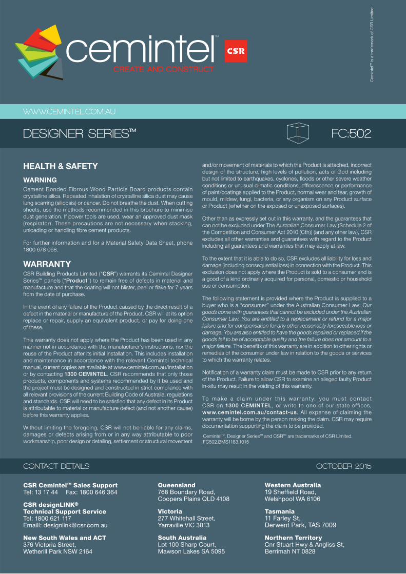
HEALTH & SAFETY
WARNINGCement Bonded Fibrous Wood Particle Board products contain
crystalline silica. Repeated inhalation of crystalline silica dust may cause
lung scarring (silicosis) or cancer. Do not breathe the dust. When cutting
sheets, use the methods recommended in this brochure to minimise
dust generation. If power tools are used, wear an approved dust mask
(respirator). These precautions are not necessary when stacking,
unloading or handling fibre cement products.
For further information and for a Material Safety Data Sheet, phone
1800 678 068.
WARRANTYCSR Building Products Limited (“CSR”) warrants its Cemintel Designer
Series™ panels (“Product”) to remain free of defects in material and
manufacture and that the coating will not blister, peel or flake for 7 years
from the date of purchase.
In the event of any failure of the Product caused by the direct result of a
defect in the material or manufacture of the Product, CSR will at its option
replace or repair, supply an equivalent product, or pay for doing one
of these.
This warranty does not apply where the Product has been used in any
manner not in accordance with the manufacturer’s instructions, nor the
reuse of the Product after its initial installation. This includes installation
and maintenance in accordance with the relevant Cemintel technical
manual, current copies are available at www.cemintel.com.au/installation
or by contacting 1300 CEMINTEL. CSR recommends that only those
products, components and systems recommended by it be used and
the project must be designed and constructed in strict compliance with
all relevant provisions of the current Building Code of Australia, regulations
and standards. CSR will need to be satisfied that any defect in its Product
is attributable to material or manufacture defect (and not another cause)
before this warranty applies.
Without limiting the foregoing, CSR will not be liable for any claims,
damages or defects arising from or in any way attributable to poor
workmanship, poor design or detailing, settlement or structural movement
and/or movement of materials to which the Product is attached, incorrect
design of the structure, high levels of pollution, acts of God including
but not limited to earthquakes, cyclones, floods or other severe weather
conditions or unusual climatic conditions, efflorescence or performance
of paint/coatings applied to the Product, normal wear and tear, growth of
mould, mildew, fungi, bacteria, or any organism on any Product surface
or Product (whether on the exposed or unexposed surfaces).
Other than as expressly set out in this warranty, and the guarantees that
can not be excluded under The Australian Consumer Law (Schedule 2 of
the Competition and Consumer Act 2010 (Cth)) (and any other law), CSR
excludes all other warranties and guarantees with regard to the Product
including all guarantees and warranties that may apply at law.
To the extent that it is able to do so, CSR excludes all liability for loss and
damage (including consequential loss) in connection with the Product. This
exclusion does not apply where the Product is sold to a consumer and is
a good of a kind ordinarily acquired for personal, domestic or household
use or consumption.
The following statement is provided where the Product is supplied to a
buyer who is a “consumer” under the Australian Consumer Law: Our
goods come with guarantees that cannot be excluded under the Australian
Consumer Law. You are entitled to a replacement or refund for a major
failure and for compensation for any other reasonably foreseeable loss or
damage. You are also entitled to have the goods repaired or replaced if the
goods fail to be of acceptable quality and the failure does not amount to a
major failure. The benefits of this warranty are in addition to other rights or
remedies of the consumer under law in relation to the goods or services
to which the warranty relates.
Notification of a warranty claim must be made to CSR prior to any return
of the Product. Failure to allow CSR to examine an alleged faulty Product
in-situ may result in the voiding of this warranty.
To make a c l a im unde r th i s wa r ran t y, you mus t contac t
CSR on 1300 CEMINTEL, or write to one of our state of f ices,
www.cemintel.com.au/contact-us. All expense of claiming the
warranty will be borne by the person making the claim. CSR may require
documentation supporting the claim to be provided.
CONTACT DETAILS
WWW.CEMINTEL.COM.AU
DESIGNER SERIES™ FC:502
OCTOBER 2015
CSR Cemintel™ Sales SupportTel: 13 17 44 Fax: 1800 646 364
CSR designLINK® Technical Support ServiceTel: 1800 621 117Emaill: [email protected]
New South Wales and ACT376 Victoria Street, Wetherill Park NSW 2164
Queensland768 Boundary Road, Coopers Plains QLD 4108
Victoria277 Whitehall Street, Yarraville VIC 3013
South AustraliaLot 100 Sharp Court, Mawson Lakes SA 5095
Western Australia19 Sheffield Road, Welshpool WA 6106
Tasmania11 Farley St, Derwent Park, TAS 7009
Northern TerritoryCnr Stuart Hwy & Angliss St, Berrimah NT 0828
Cemintel™, Designer Series™ and CSR™ are trademarks of CSR Limited.
FC502.BMS1183.1015
Cem
inte
l™ is a
tra
dem
ark
of C
SR
Lim
ited