Embed Size (px)
Citation preview

2 3
Designers and Manufacturers of HighPower Microwave Amplifiers and Systems Microwave applications are
advancing rapidly, shapingthe world we live in
InnovationSince 1987 MILMEGA Ltd has been designing, developing andmanufacturing solid state high-power broadband amplifiers for commercialand government purposes. Our amplifier products range in frequency from500 MHz to 14 GHz, with power levels from one watt to above one kilowatt.
Reputation Based on the Isle of Wight, off the south coast of England, MILMEGA pridesitself on having built a reputation for a flexible and dynamic approach tomeeting customer requirements.
TraditionIt is the MILMEGA tradition to go the extra mile to take the complexity out ofamplifier ownership. We have a proven pedigree for quality and reliability.We combine this with first class technical specifications and a responsivenessthat you would expect from a high calibre organisation.
Our PromiseWe believe that MILMEGA amplifiers are the best you can invest in.Our promise to our customers is simple.... We deliver the type of service you deserve, when you want it.
With MILMEGA as yourpartner, you can be sure ofmaximising your potential
4 5
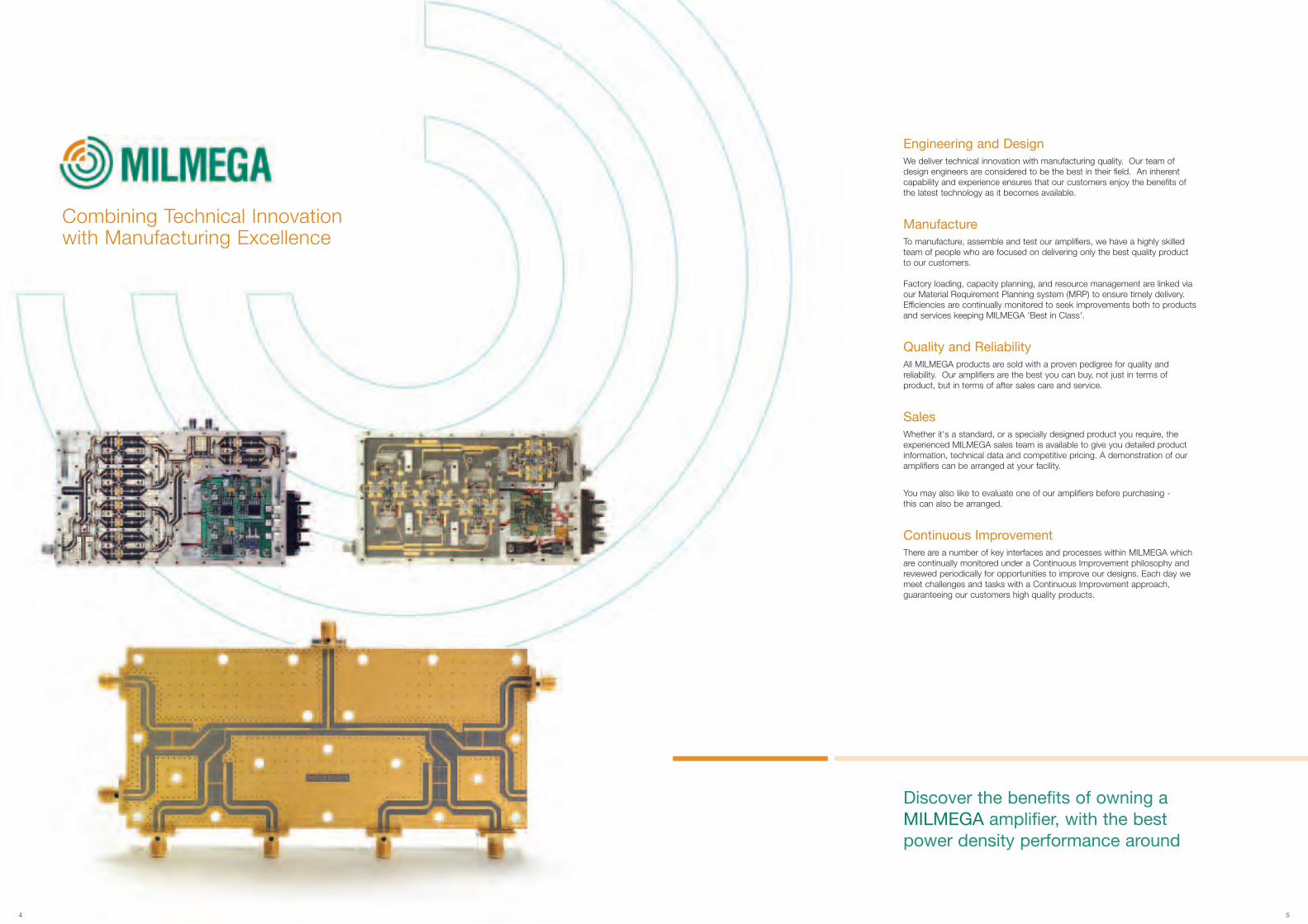
Combining Technical Innovationwith Manufacturing Excellence
Discover the benefits of owning aMILMEGA amplifier, with the bestpower density performance around
Engineering and DesignWe deliver technical innovation with manufacturing quality. Our team ofdesign engineers are considered to be the best in their field. An inherentcapability and experience ensures that our customers enjoy the benefits ofthe latest technology as it becomes available.
ManufactureTo manufacture, assemble and test our amplifiers, we have a highly skilledteam of people who are focused on delivering only the best quality productto our customers.
Factory loading, capacity planning, and resource management are linked viaour Material Requirement Planning system (MRP) to ensure timely delivery.Efficiencies are continually monitored to seek improvements both to productsand services keeping MILMEGA 'Best in Class'.
Quality and ReliabilityAll MILMEGA products are sold with a proven pedigree for quality andreliability. Our amplifiers are the best you can buy, not just in terms ofproduct, but in terms of after sales care and service.
SalesWhether it's a standard, or a specially designed product you require, theexperienced MILMEGA sales team is available to give you detailed productinformation, technical data and competitive pricing. A demonstration of ouramplifiers can be arranged at your facility.
You may also like to evaluate one of our amplifiers before purchasing -this can also be arranged.
Continuous ImprovementThere are a number of key interfaces and processes within MILMEGA whichare continually monitored under a Continuous Improvement philosophy andreviewed periodically for opportunities to improve our designs. Each day wemeet challenges and tasks with a Continuous Improvement approach,guaranteeing our customers high quality products.

6 7
The MILMEGA Advantage
The Power Density AdvantageMore Power for half the size and weight. Our range of broad band Class Asolid state amplifiers deliver the required power in a package which is half thesize and weight of our competitors. Superior P1dB gives a better $/watt ratioand first class harmonic and spurious specifications are all powerful testimonyto our ability as microwave amplifier designers.
The Dual Band AdvantageWith dual band solution you pay for what you need. At MILMEGA we have developed a dual band approach to maximiseperformance across multiple octave bands. We get more power across atarget band, a minimum of 10 to 20dB improvement in harmonic levels,superior ACPR performance, improved phase performance with reducedpower supply requirements and a superior MTBF.
The Warranty Advantage - 5 Year WarrantyYou may never need it, but it’s good to know it’s there. It is our belief that our amplifiers are the best you will buy, so if you areunfortunate enough to experience a problem within the first 5 years ofownership we will collect the amplifier at our expense and guarantee to haveit repaired and available for return within 48 hours of its arrival at our factory.You will bear no hidden costs. Contact the factory for more details
The Interface AdvantageWe have leveraged the latest interface technologies to bring you the first lowcost, web based control of microwave power amplifiers. Combining Ethernet,USB and RS232 protocols means that you get ‘plug and play’ simplicity inamplifier interfacing.
The Upgrade AdvantageUpgrading your amplifier is easier than upgrading your PC. We all know how fast technology can move. Before you know it your currentamplifier is just not up to the job it was originally intended for. MILMEGA canoffer an easy upgrade solution for both frequency and power. Our CorporateStructure Amplifier topology and unique modular design approach ensuresthat upgrading your amplifier is painless and cost effective.
Diverse ApplicationsDelivering Products for Worldwide Applications
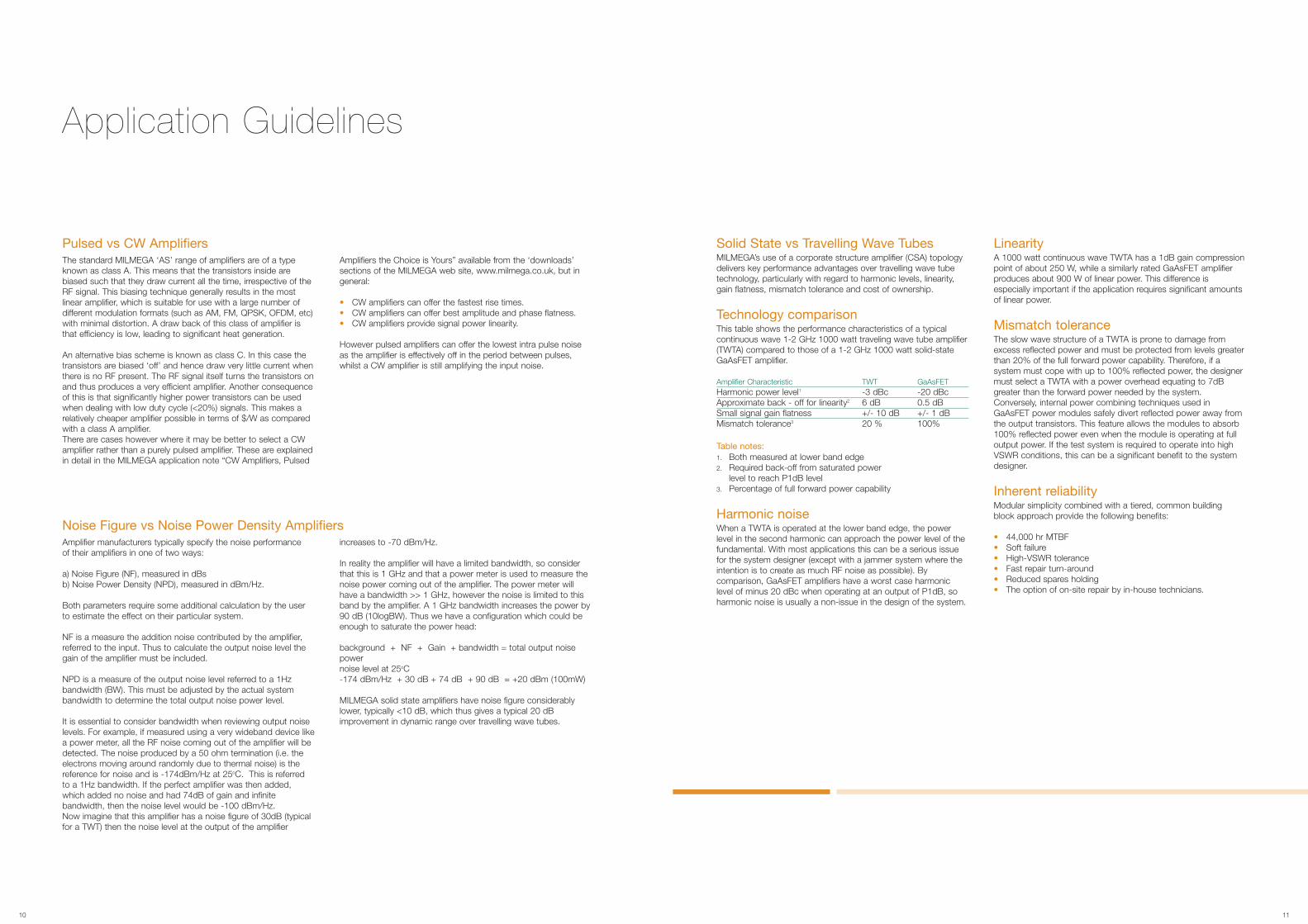
Saturated Output Power (Psat)This is a measure of the maximum power of the amplifier. As thegain of the amplifier varies across the band, different frequencieswill saturate at different input levels. MILMEGA production testsset the optimum input power level for the measurement. A plot ismade at a fixed input power level across the band. Thus atspecific frequencies the amplifier may be overdriven (reducedoutput power), or underdriven (the amplifier has not reachedsaturation). The result is therefore conservative and shows theminimum saturated power level.
1dB Compressed Output Power (P1dB)The 1dB compressed output power is that point at which the gainof the amplifier has fallen by 1dB from its signal value. MILMEGAamplifiers are tested to ensure that their P1dB compression pointexceeds the specified minimum value. Harmonics
The harmonic output level of an amplifier generally depends uponits fundamental output power level, or more specifically how far itis driven into its non-linear region. Harmonics are usuallymeasured with respect to the fundamental level, at a given outputpower level. In MILMEGA’s test lab the operating band is firstswept at the rate (P1dB) output power and the harmonic outputlevels observed on a spectrum analyser. The worst caseharmonic is noted and subsequent harmonic measurements aremade. The result is recorded in dB relative to the fundamentallevel, i.e. dBc. When characterisation is required the amplifier isstepped across the operating band and, at each frequency thefundamental, 2nd and 3rd harmonic levels are measured. This isdone at three different power levels corresponding to linear (10 dBbelow the specified 1dB compression point), 1dB compressed,and saturated operation. A graph is then produced showing therejection of the harmonics at the different power levels.
Adjacent Channel Power Ratio (ACPR)MeasurementsThis is another measure of linearity, specifically aimed at digitallymodulated systems. ACPR is the result of intermodulation fromthe complex signal in the pass band. A key factor is the CrestFactor (CF). This is the ratio of peak power level to the averagepower level of the pass band signal. It is important whencomparing ACPR performance between amplifiers to check thecrest factor of the test signal. In MILMEGA characterisation testswe take a worst case approach and use a CF of 11dB, a lowerCF will improve the ACPR.
9
Performance TestingBecause test methods employed across the industry vary, it is important tounderstand how each test is performed so that the resuts can be properly interpreted
8
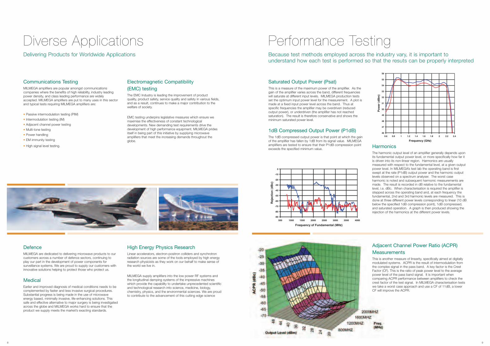
DefenceMILMEGA are dedicated to delivering microwave products to ourcustomers across a number of defence sectors, continuing toplay our part in the development of power components forsurveillance systems. We are proud to supply our customers withinnovative solutions helping to protect those who protect us.
MedicalEarlier and improved diagnosis of medical conditions needs to becomplemented by faster and less invasive surgical procedures.Substantial progress is being made in the use of microwaveenergy based, minimally invasive, life-enhancing solutions. Thissafe and effective alternative to major surgery is being investigatedacross the globe and MILMEGA works hard to ensure that theproduct we supply meets the market’s exacting standards.
High Energy Physics ResearchLinear accelerators, electron-positron colliders and synchrotronradiation sources are some of the tools employed by high energyresearch physicists as they work on our behalf to make sense ofthe world we live in.
MILMEGA supply amplifiers into the low power RF systems andthe longitudinal damping systems of the impressive machineswhich provide the capability to undertake unprecedented scientificand technological research into science, medicine, biology,chemistry, physics, and the environmental sciences. We are proudto contribute to the advancement of this cutting edge science
Communications TestingMILMEGA amplifiers are popular amongst communicationscompanies where the benefits of high reliability, industry leadingpower density, and class leading performance are widelyaccepted. MILMEGA amplifiers are put to many uses in this sectorand typical tests requiring MILMEGA amplifiers are:
• Passive intermodulation testing (PIM)
• Intermodulation testing (IM)
• Adjacent channel power testing
• Multi-tone testing
• Power handling
• EM immunity testing
• High signal level testing.
Electromagnetic Compatibility(EMC) testingThe EMC Industry is leading the improvement of productquality, product safety, service quality and safety in various fields,and as a result, continues to make a major contribution to thewelfare of society.
EMC testing underpins legislative measures which ensure wemaximise the effectiveness of constant technologicaldevelopments. New demanding test requirements drive thedevelopment of high performance equipment. MILMEGA pridesitself in being part of this initiative by supplying microwaveamplifiers that meet the increasing demands throughout theglobe.
Application Guidelines
Solid State vs Travelling Wave TubesMILMEGA’s use of a corporate structure amplifier (CSA) topologydelivers key performance advantages over travelling wave tubetechnology, particularly with regard to harmonic levels, linearity,gain flatness, mismatch tolerance and cost of ownership.
Technology comparisonThis table shows the performance characteristics of a typicalcontinuous wave 1-2 GHz 1000 watt traveling wave tube amplifier(TWTA) compared to those of a 1-2 GHz 1000 watt solid-stateGaAsFET amplifier.
Amplifier Characteristic TWT GaAsFETHarmonic power level1 -3 dBc -20 dBcApproximate back - off for linearity2 6 dB 0.5 dBSmall signal gain flatness +/- 10 dB +/- 1 dBMismatch tolerance3 20 % 100%
Table notes:1. Both measured at lower band edge2. Required back-off from saturated power
level to reach P1dB level3. Percentage of full forward power capability
Harmonic noiseWhen a TWTA is operated at the lower band edge, the powerlevel in the second harmonic can approach the power level of thefundamental. With most applications this can be a serious issuefor the system designer (except with a jammer system where theintention is to create as much RF noise as possible). Bycomparison, GaAsFET amplifiers have a worst case harmoniclevel of minus 20 dBc when operating at an output of P1dB, soharmonic noise is usually a non-issue in the design of the system.
LinearityA 1000 watt continuous wave TWTA has a 1dB gain compressionpoint of about 250 W, while a similarly rated GaAsFET amplifierproduces about 900 W of linear power. This difference isespecially important if the application requires significant amountsof linear power.
Mismatch toleranceThe slow wave structure of a TWTA is prone to damage fromexcess reflected power and must be protected from levels greaterthan 20% of the full forward power capability. Therefore, if asystem must cope with up to 100% reflected power, the designermust select a TWTA with a power overhead equating to 7dBgreater than the forward power needed by the system.Conversely, internal power combining techniques used inGaAsFET power modules safely divert reflected power away fromthe output transistors. This feature allows the modules to absorb100% reflected power even when the module is operating at fulloutput power. If the test system is required to operate into highVSWR conditions, this can be a significant benefit to the systemdesigner.
Inherent reliabilityModular simplicity combined with a tiered, common buildingblock approach provide the following benefits:
• 44,000 hr MTBF• Soft failure• High-VSWR tolerance• Fast repair turn-around• Reduced spares holding• The option of on-site repair by in-house technicians.
The standard MILMEGA ‘AS’ range of amplifiers are of a typeknown as class A. This means that the transistors inside arebiased such that they draw current all the time, irrespective of theRF signal. This biasing technique generally results in the mostlinear amplifier, which is suitable for use with a large number ofdifferent modulation formats (such as AM, FM, QPSK, OFDM, etc)with minimal distortion. A draw back of this class of amplifier isthat efficiency is low, leading to significant heat generation.
An alternative bias scheme is known as class C. In this case thetransistors are biased ‘off’ and hence draw very little current whenthere is no RF present. The RF signal itself turns the transistors onand thus produces a very efficient amplifier. Another consequenceof this is that significantly higher power transistors can be usedwhen dealing with low duty cycle (<20%) signals. This makes arelatively cheaper amplifier possible in terms of $/W as comparedwith a class A amplifier.There are cases however where it may be better to select a CWamplifier rather than a purely pulsed amplifier. These are explainedin detail in the MILMEGA application note “CW Amplifiers, Pulsed
Amplifiers the Choice is Yours” available from the ‘downloads’sections of the MILMEGA web site, www.milmega.co.uk, but ingeneral:
• CW amplifiers can offer the fastest rise times.• CW amplifiers can offer best amplitude and phase flatness.• CW amplifiers provide signal power linearity.
However pulsed amplifiers can offer the lowest intra pulse noiseas the amplifier is effectively off in the period between pulses,whilst a CW amplifier is still amplifying the input noise.
Pulsed vs CW Amplifiers
Amplifier manufacturers typically specify the noise performanceof their amplifiers in one of two ways:
a) Noise Figure (NF), measured in dBsb) Noise Power Density (NPD), measured in dBm/Hz.
Both parameters require some additional calculation by the userto estimate the effect on their particular system.
NF is a measure the addition noise contributed by the amplifier,referred to the input. Thus to calculate the output noise level thegain of the amplifier must be included.
NPD is a measure of the output noise level referred to a 1Hzbandwidth (BW). This must be adjusted by the actual systembandwidth to determine the total output noise power level.
It is essential to consider bandwidth when reviewing output noiselevels. For example, if measured using a very wideband device likea power meter, all the RF noise coming out of the amplifier will bedetected. The noise produced by a 50 ohm termination (i.e. theelectrons moving around randomly due to thermal noise) is thereference for noise and is -174dBm/Hz at 25oC. This is referredto a 1Hz bandwidth. If the perfect amplifier was then added,which added no noise and had 74dB of gain and infinitebandwidth, then the noise level would be -100 dBm/Hz.Now imagine that this amplifier has a noise figure of 30dB (typicalfor a TWT) then the noise level at the output of the amplifier
increases to -70 dBm/Hz.
In reality the amplifier will have a limited bandwidth, so considerthat this is 1 GHz and that a power meter is used to measure thenoise power coming out of the amplifier. The power meter willhave a bandwidth >> 1 GHz, however the noise is limited to thisband by the amplifier. A 1 GHz bandwidth increases the power by90 dB (10logBW). Thus we have a configuration which could beenough to saturate the power head:
background + NF + Gain + bandwidth = total output noisepowernoise level at 25oC-174 dBm/Hz + 30 dB + 74 dB + 90 dB = +20 dBm (100mW)
MILMEGA solid state amplifiers have noise figure considerablylower, typically <10 dB, which thus gives a typical 20 dBimprovement in dynamic range over travelling wave tubes.
Noise Figure vs Noise Power Density Amplifiers
10 11
12 13
Custom DesignAlthough our amplifier product range represents the best ofbreed in the world today, we recognise that many requirementscannot be met through standard amplifier products.
When a specially-tailored solution is required, our designengineers will work with you to find the most appropriate way ofmeeting your criteria. We will discuss your amplifier performanceobjectives, then respond with a proposal that combines technicalinnovation with manufacturing quality. No matter how demandingyour high-power amplifier specification, we will deliver a solutionthat fulfils your needs.
PrototypeThe next step in our relationship with you is to produce aprototype of the amplifier for further discussion and testing. Here we are able to use extensive in-house resources to ensurethat your project is completed in the shortest possible time scale.
DesignOur design engineers will ensure that our amplifier proposalsalways represent the most appropriate solution for your needs.When formulating proposals, we will consider the followingimportant factors to ensure you get what you want, whenyou want:
• Function• Reliability• Quantity• Cost effective technologies• Time scale• Component availability.
ProductionWith final agreement on design and performance of the prototype,MILMEGA will address production. We can undertake lower-volume amplifier production using our own advancedmanufacturing facilities, or manage the sub-contracting of high-volume work.
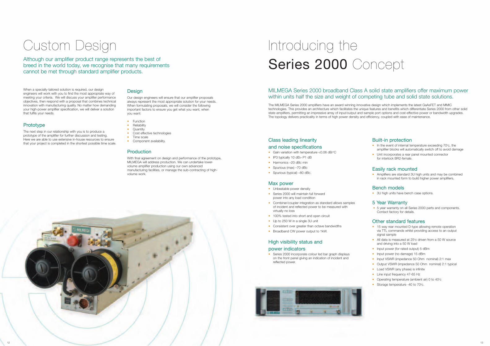
Introducing theSeries 2000 Concept
MILMEGA Series 2000 broadband Class A solid state amplifiers offer maximum powerwithin units half the size and weight of competing tube and solid state solutions. The MILMEGA Series 2000 amplifiers have an award winning innovative design which implements the latest GaAsFET and MMICtechnologies. This provides an architecture which facilitates the unique features and benefits which differentiate Series 2000 from other solidstate amplifiers, permitting an impressive array of input/output and sample port options and cost-effective power or bandwidth upgrades.The topology delivers practicality in terms of high power density and efficiency, coupled with ease of maintenance.
Class leading linearityand noise specifications• Gain variation with temperature <0.06 dB/oC
• IP3 typically 10 dB> P1 dB
• Harmonics –20 dBc min
• Spurious (max) –70 dBc
• Spurious (typical) –80 dBc.
Max power• Unbeatable power density
• Series 2000 will maintain full forwardpower into any load condition
• Combiner/coupler integration as standard allows samplesof incident and reflected power to be measured withvirtually no loss
• 100% tested into short and open circuit
• Up to 250 W in a single 3U unit
• Consistent over greater than octave bandwidths
• Broadband CW power output to 1kW.
High visibility status andpower indicators• Series 2000 incorporate colour led bar graph displays
on the front panel giving an indication of incident andreflected power.
Built-in protection• In the event of internal temperature exceeding 70oc, the
amplifier blocks will automatically switch off to avoid damage
• Unit incorporates a rear panel mounted connectorfor interlock BR2-female.
Easily rack mounted• Amplifiers are standard 3U high units and may be combined
in rack mounted form to build higher power amplifiers.
Bench models• 3U high units have bench case options.
5 Year Warranty• 5 year warranty on all Series 2000 parts and components.
Contact factory for details.
Other standard features• 15 way rear mounted D-type allowing remote operation
via TTL commands whilst providing access to an outputsignal sample
• All data is measured at 25oc driven from a 50 W sourceand driving into a 50 W load
• Input power (for rated output) 5 dBm
• Input power (no damage) 15 dBm
• Input VSWR (impedance 50 Ohm nominal) 2:1 max
• Output VSWR (impedance 50 Ohm nominal) 2:1 typical
• Load VSWR (any phase) is infinite
• Line input frequency 47-65 Hz
• Operating temperature (ambient air) 0 to 40oc
• Storage temperature -40 to 70oc.
14 15
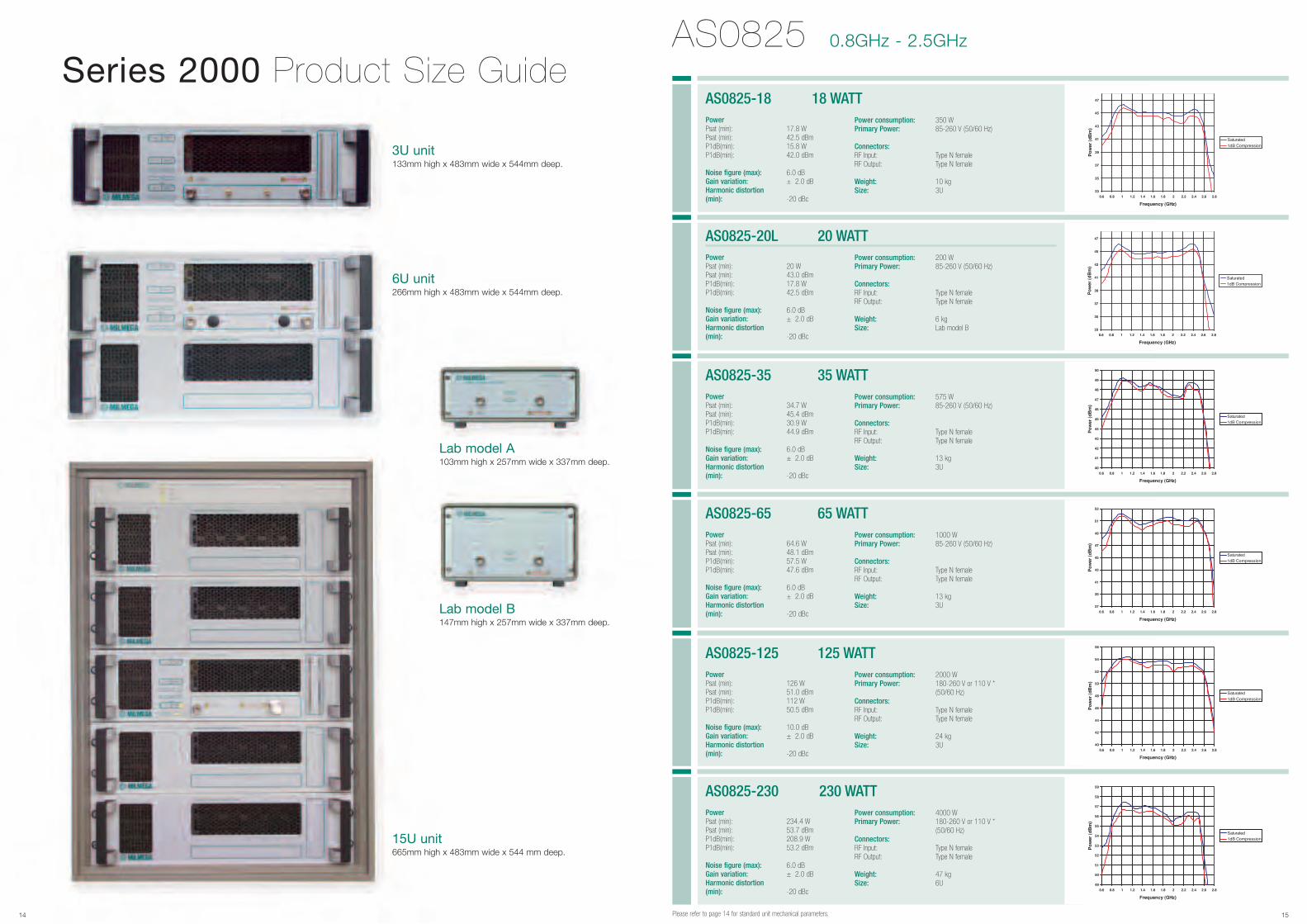
Series 2000 Product Size Guide
Lab model A103mm high x 257mm wide x 337mm deep.
Lab model B147mm high x 257mm wide x 337mm deep.
3U unit133mm high x 483mm wide x 544mm deep.
6U unit266mm high x 483mm wide x 544mm deep.
15U unit665mm high x 483mm wide x 544 mm deep.
Power Psat (min): 17.8 W Psat (min): 42.5 dBmP1dB(min): 15.8 W P1dB(min): 42.0 dBm
Noise figure (max): 6.0 dBGain variation: ± 2.0 dBHarmonic distortion (min): -20 dBc
AS0825-18 18 WATTPower consumption: 350 WPrimary Power: 85-260 V (50/60 Hz)
Connectors:RF Input: Type N female RF Output: Type N female
Weight: 10 kgSize: 3U
AS0825 0.8GHz - 2.5GHz
Please refer to page 14 for standard unit mechanical parameters.
Power Psat (min): 20 W Psat (min): 43.0 dBmP1dB(min): 17.8 W P1dB(min): 42.5 dBm
Noise figure (max): 6.0 dBGain variation: ± 2.0 dBHarmonic distortion (min): -20 dBc
AS0825-20L 20 WATTPower consumption: 200 WPrimary Power: 85-260 V (50/60 Hz)
Connectors:RF Input: Type N female RF Output: Type N female
Weight: 6 kgSize: Lab model B
Power Psat (min): 34.7 W Psat (min): 45.4 dBmP1dB(min): 30.9 W P1dB(min): 44.9 dBm
Noise figure (max): 6.0 dBGain variation: ± 2.0 dBHarmonic distortion (min): -20 dBc
AS0825-35 35 WATTPower consumption: 575 WPrimary Power: 85-260 V (50/60 Hz)
Connectors:RF Input: Type N female RF Output: Type N female
Weight: 13 kgSize: 3U
Power Psat (min): 64.6 W Psat (min): 48.1 dBmP1dB(min): 57.5 W P1dB(min): 47.6 dBm
Noise figure (max): 6.0 dBGain variation: ± 2.0 dBHarmonic distortion (min): -20 dBc
AS0825-65 65 WATTPower consumption: 1000 WPrimary Power: 85-260 V (50/60 Hz)
Connectors:RF Input: Type N female RF Output: Type N female
Weight: 13 kgSize: 3U
Power Psat (min): 126 W Psat (min): 51.0 dBmP1dB(min): 112 W P1dB(min): 50.5 dBm
Noise figure (max): 10.0 dBGain variation: ± 2.0 dBHarmonic distortion (min): -20 dBc
AS0825-125 125 WATTPower consumption: 2000 WPrimary Power: 180-260 V or 110 V *
(50/60 Hz)Connectors:RF Input: Type N female RF Output: Type N female
Weight: 24 kgSize: 3U
Power Psat (min): 234.4 W Psat (min): 53.7 dBmP1dB(min): 208.9 W P1dB(min): 53.2 dBm
Noise figure (max): 6.0 dBGain variation: ± 2.0 dBHarmonic distortion (min): -20 dBc
AS0825-230 230 WATTPower consumption: 4000 WPrimary Power: 180-260 V or 110 V *
(50/60 Hz)Connectors:RF Input: Type N female RF Output: Type N female
Weight: 47 kgSize: 6U
16 17
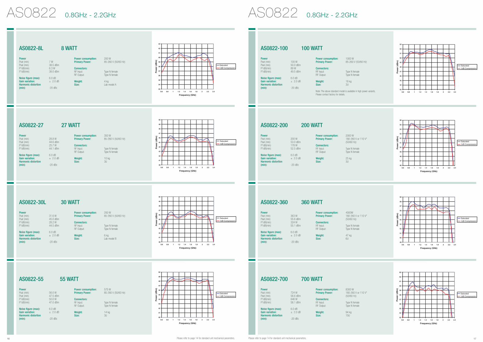
AS0822 0.8GHz - 2.2GHz AS0822 0.8GHz - 2.2GHz
Please refer to page 14 for standard unit mechanical parameters.Please refer to page 14 for standard unit mechanical parameters.
Power Psat (min): 7 W Psat (min): 38.5 dBmP1dB(min): 6.3 W P1dB(min): 38.0 dBm
Noise figure (max): 6.0 dBGain variation: ± 2.0 dBHarmonic distortion (min): -20 dBc
AS0822-8L 8 WATT
Power consumption: 200 WPrimary Power: 85-260 V (50/60 Hz)
Connectors:RF Input: Type N female RF Output: Type N female
Weight: 4 kgSize: Lab model A
Power Psat (min): 28.8 W Psat (min): 44.6 dBmP1dB(min): 25.7 W P1dB(min): 44.1 dBm
Noise figure (max): 6.0 dBGain variation: ± 2.0 dBHarmonic distortion (min): -20 dBc
AS0822-27 27 WATT
Power consumption: 350 WPrimary Power: 85-260 V (50/60 Hz)
Connectors:RF Input: Type N female RF Output: Type N female
Weight: 10 kgSize: 3U
Power Psat (min): 31.6 W Psat (min): 45.0 dBmP1dB(min): 28.2 W P1dB(min): 44.5 dBm
Noise figure (max): 6.0 dBGain variation: ± 2.0 dBHarmonic distortion (min): -20 dBc
AS0822-30L 30 WATT
Power consumption: 200 WPrimary Power: 85-260 V (50/60 Hz)
Connectors:RF Input: Type N female RF Output: Type N female
Weight: 6 kgSize: Lab model B
Power Psat (min): 56.0 W Psat (min): 47.5 dBmP1dB(min): 50.0 W P1dB(min): 47.0 dBm
Noise figure (max): 6.0 dBGain variation: ± 2.0 dBHarmonic distortion (min): -20 dBc
AS0822-55 55 WATT
Power consumption: 575 WPrimary Power: 85-260 V (50/60 Hz)
Connectors:RF Input: Type N female RF Output: Type N female
Weight: 14 kgSize: 3U
Power Psat (min): 100 W Psat (min): 50.0 dBmP1dB(min): 89 W P1dB(min): 49.5 dBm
Noise figure (max): 6.0 dBGain variation: ± 2.0 dBHarmonic distortion (min): -20 dBc
AS0822-100 100 WATT
Power consumption: 1000 WPrimary Power: 85-260 V (50/60 Hz)
Connectors:RF Input: Type N female RF Output: Type N female
Weight: 18 kgSize: 3U
Note: The above standard model is available in high power variants,Please contact factory for details.
Power Psat (min): 200 W Psat (min): 53.0 dBmP1dB(min): 178 W P1dB(min): 52.5 dBm
Noise figure (max): 6.0 dBGain variation: ± 2.0 dBHarmonic distortion (min): -20 dBc
AS0822-200 200 WATT
Power consumption: 2000 WPrimary Power: 180-260 V or 110 V*
(50/60 Hz)Connectors:RF Input: Type N female RF Output: Type N female
Weight: 25 kgSize: 3U
Power Psat (min): 363 W Psat (min): 55.6 dBmP1dB(min): 324 W P1dB(min): 55.1 dBm
Noise figure (max): 6.0 dBGain variation: ± 2.0 dBHarmonic distortion (min): -20 dBc
AS0822-360 360 WATT
Power consumption: 4000WPrimary Power: 180-260 V or 110 V*
(50/60 Hz)Connectors:RF Input: Type N female RF Output: Type N female
Weight: 47 kgSize: 6U
Power Psat (min): 724 W Psat (min): 58.6 dBmP1dB(min): 646 W P1dB(min): 58.1 dBm
Noise figure (max): 6.0 dBGain variation: ± 2.0 dBHarmonic distortion (min): -20 dBc
AS0822-700 700 WATT
Power consumption: 8300 WPrimary Power: 180-260 V or 110 V*
(50/60 Hz)Connectors:RF Input: Type N female RF Output: Type N female
Weight: 94 kgSize: 15U
18 19
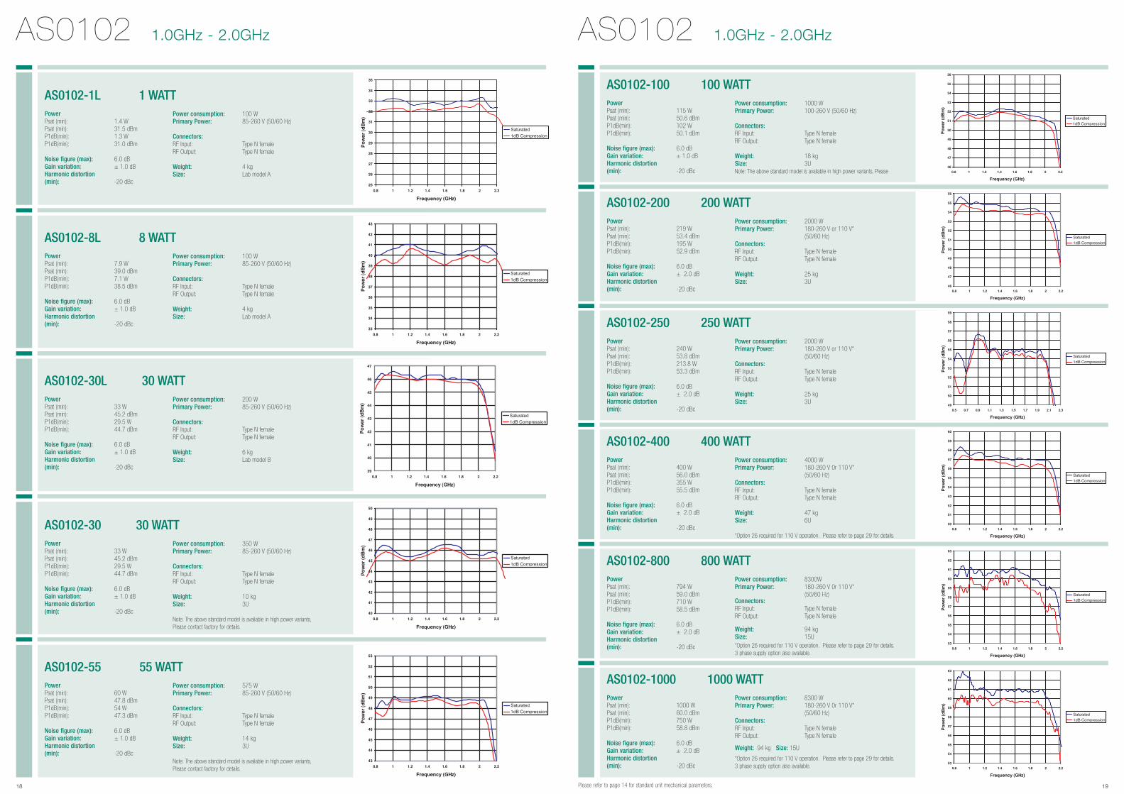
AS0102 1.0GHz - 2.0GHz AS0102 1.0GHz - 2.0GHz
Please refer to page 14 for standard unit mechanical parameters.
Power Psat (min): 1.4 W Psat (min): 31.5 dBmP1dB(min): 1.3 W P1dB(min): 31.0 dBm
Noise figure (max): 6.0 dBGain variation: ± 1.0 dBHarmonic distortion (min): -20 dBc
AS0102-1L 1 WATTPower consumption: 100 WPrimary Power: 85-260 V (50/60 Hz)
Connectors:RF Input: Type N female RF Output: Type N female
Weight: 4 kgSize: Lab model A
Power Psat (min): 7.9 W Psat (min): 39.0 dBmP1dB(min): 7.1 W P1dB(min): 38.5 dBm
Noise figure (max): 6.0 dBGain variation: ± 1.0 dBHarmonic distortion (min): -20 dBc
AS0102-8L 8 WATTPower consumption: 100 WPrimary Power: 85-260 V (50/60 Hz)
Connectors:RF Input: Type N female RF Output: Type N female
Weight: 4 kgSize: Lab model A
Power Psat (min): 33 W Psat (min): 45.2 dBmP1dB(min): 29.5 W P1dB(min): 44.7 dBm
Noise figure (max): 6.0 dBGain variation: ± 1.0 dBHarmonic distortion (min): -20 dBc
AS0102-30L 30 WATTPower consumption: 200 WPrimary Power: 85-260 V (50/60 Hz)
Connectors:RF Input: Type N female RF Output: Type N female
Weight: 6 kgSize: Lab model B
Power Psat (min): 33 W Psat (min): 45.2 dBmP1dB(min): 29.5 W P1dB(min): 44.7 dBm
Noise figure (max): 6.0 dBGain variation: ± 1.0 dBHarmonic distortion (min): -20 dBc
AS0102-30 30 WATTPower consumption: 350 WPrimary Power: 85-260 V (50/60 Hz)
Connectors:RF Input: Type N female RF Output: Type N female
Weight: 10 kgSize: 3U
Note: The above standard model is available in high power variants,Please contact factory for details.
Power Psat (min): 60 W Psat (min): 47.8 dBmP1dB(min): 54 W P1dB(min): 47.3 dBm
Noise figure (max): 6.0 dBGain variation: ± 1.0 dBHarmonic distortion (min): -20 dBc
AS0102-55 55 WATTPower consumption: 575 WPrimary Power: 85-260 V (50/60 Hz)
Connectors:RF Input: Type N female RF Output: Type N female
Weight: 14 kgSize: 3U
Note: The above standard model is available in high power variants,Please contact factory for details.
Power Psat (min): 115 W Psat (min): 50.6 dBmP1dB(min): 102 W P1dB(min): 50.1 dBm
Noise figure (max): 6.0 dBGain variation: ± 1.0 dBHarmonic distortion (min): -20 dBc
AS0102-100 100 WATTPower consumption: 1000 WPrimary Power: 100-260 V (50/60 Hz)
Connectors:RF Input: Type N female RF Output: Type N female
Weight: 18 kgSize: 3UNote: The above standard model is available in high power variants, Please
Power Psat (min): 219 W Psat (min): 53.4 dBmP1dB(min): 195 W P1dB(min): 52.9 dBm
Noise figure (max): 6.0 dBGain variation: ± 2.0 dBHarmonic distortion (min): -20 dBc
AS0102-200 200 WATTPower consumption: 2000 WPrimary Power: 180-260 V or 110 V*
(50/60 Hz)Connectors:RF Input: Type N female RF Output: Type N female
Weight: 25 kgSize: 3U
Power Psat (min): 240 W Psat (min): 53.8 dBmP1dB(min): 213.8 W P1dB(min): 53.3 dBm
Noise figure (max): 6.0 dBGain variation: ± 2.0 dBHarmonic distortion (min): -20 dBc
AS0102-250 250 WATTPower consumption: 2000 WPrimary Power: 180-260 V or 110 V*
(50/60 Hz)Connectors:RF Input: Type N female RF Output: Type N female
Weight: 25 kgSize: 3U
Power Psat (min): 400 W Psat (min): 56.0 dBmP1dB(min): 355 W P1dB(min): 55.5 dBm
Noise figure (max): 6.0 dBGain variation: ± 2.0 dBHarmonic distortion (min): -20 dBc
AS0102-400 400 WATTPower consumption: 4000 WPrimary Power: 180-260 V 0r 110 V*
(50/60 Hz)Connectors:RF Input: Type N female RF Output: Type N female
Weight: 47 kgSize: 6U
*Option 26 required for 110 V operation. Please refer to page 29 for details.
Power Psat (min): 794 W Psat (min): 59.0 dBmP1dB(min): 710 W P1dB(min): 58.5 dBm
Noise figure (max): 6.0 dBGain variation: ± 2.0 dBHarmonic distortion (min): -20 dBc
AS0102-800 800 WATTPower consumption: 8300WPrimary Power: 180-260 V 0r 110 V*
(50/60 Hz)Connectors:RF Input: Type N female RF Output: Type N female
Weight: 94 kgSize: 15U*Option 26 required for 110 V operation. Please refer to page 29 for details.3 phase supply option also available.
Power Psat (min): 1000 W Psat (min): 60.0 dBmP1dB(min): 750 W P1dB(min): 58.8 dBm
Noise figure (max): 6.0 dBGain variation: ± 2.0 dBHarmonic distortion (min): -20 dBc
AS0102-1000 1000 WATTPower consumption: 8300 WPrimary Power: 180-260 V 0r 110 V*
(50/60 Hz)Connectors:RF Input: Type N female RF Output: Type N female
Weight: 94 kg Size: 15U
*Option 26 required for 110 V operation. Please refer to page 29 for details.3 phase supply option also available.
20 21
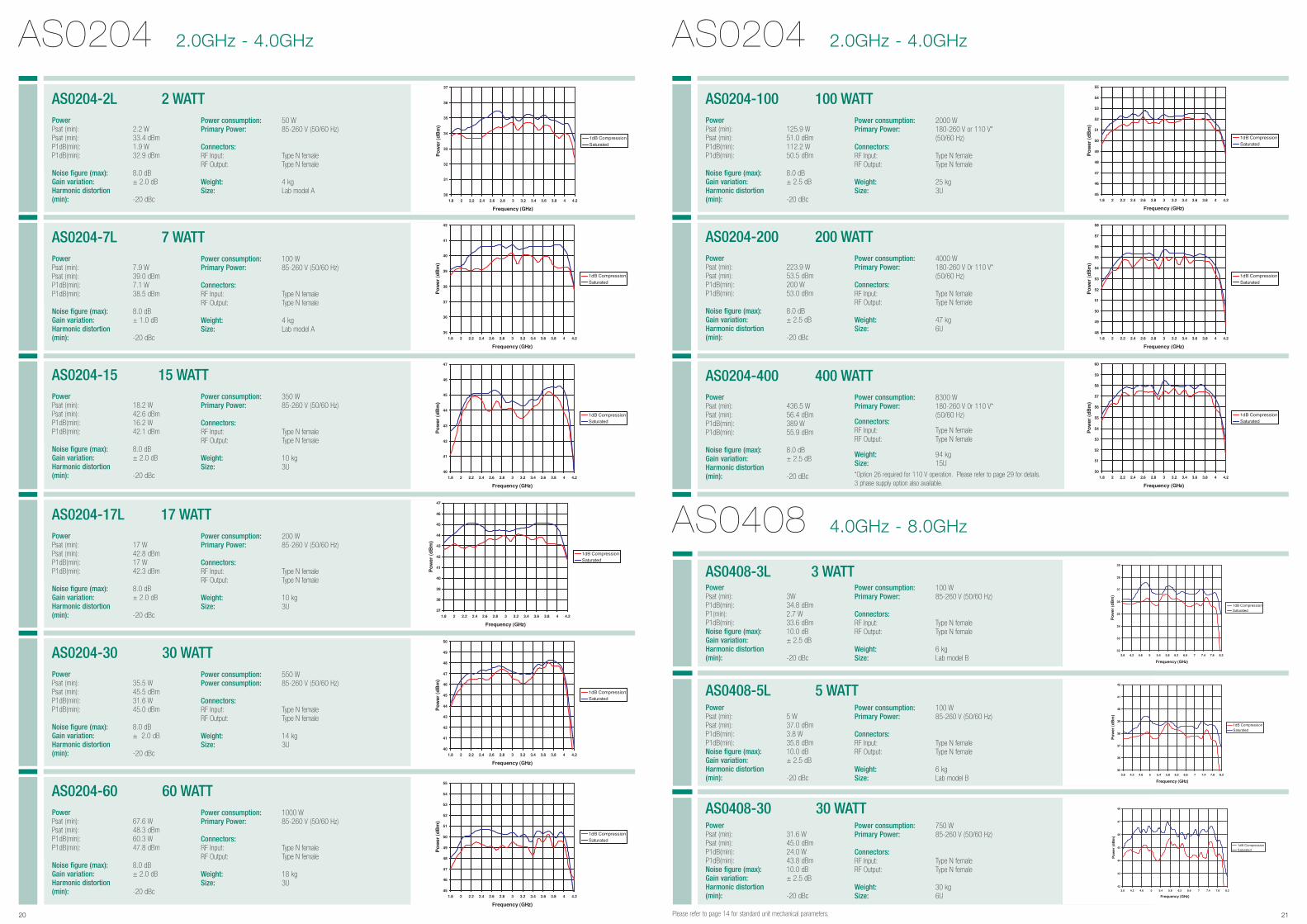
AS0204 2.0GHz - 4.0GHz
Please refer to page 14 for standard unit mechanical parameters.
AS0204 2.0GHz - 4.0GHz
AS0408 4.0GHz - 8.0GHz
Power Psat (min): 2.2 W Psat (min): 33.4 dBmP1dB(min): 1.9 W P1dB(min): 32.9 dBm
Noise figure (max): 8.0 dBGain variation: ± 2.0 dBHarmonic distortion (min): -20 dBc
AS0204-2L 2 WATTPower consumption: 50 WPrimary Power: 85-260 V (50/60 Hz)
Connectors:RF Input: Type N female RF Output: Type N female
Weight: 4 kgSize: Lab model A
Power Psat (min): 125.9 W Psat (min): 51.0 dBmP1dB(min): 112.2 W P1dB(min): 50.5 dBm
Noise figure (max): 8.0 dBGain variation: ± 2.5 dBHarmonic distortion (min): -20 dBc
AS0204-100 100 WATTPower consumption: 2000 WPrimary Power: 180-260 V or 110 V*
(50/60 Hz)Connectors:RF Input: Type N female RF Output: Type N female
Weight: 25 kgSize: 3U
Power Psat (min): 3W P1dB(min): 34.8 dBmP1(min): 2.7 W P1dB(min): 33.6 dBmNoise figure (max): 10.0 dBGain variation: ± 2.5 dBHarmonic distortion (min): -20 dBc
AS0408-3L 3 WATTPower consumption: 100 WPrimary Power: 85-260 V (50/60 Hz)
Connectors:RF Input: Type N female RF Output: Type N female
Weight: 6 kgSize: Lab model B
Power Psat (min): 5 W Psat (min): 37.0 dBmP1dB(min): 3.8 W P1dB(min): 35.8 dBmNoise figure (max): 10.0 dBGain variation: ± 2.5 dBHarmonic distortion (min): -20 dBc
AS0408-5L 5 WATTPower consumption: 100 WPrimary Power: 85-260 V (50/60 Hz)
Connectors:RF Input: Type N female RF Output: Type N female
Weight: 6 kgSize: Lab model B
Power Psat (min): 31.6 W Psat (min): 45.0 dBmP1dB(min): 24.0 W P1dB(min): 43.8 dBmNoise figure (max): 10.0 dBGain variation: ± 2.5 dBHarmonic distortion (min): -20 dBc
AS0408-30 30 WATTPower consumption: 750 WPrimary Power: 85-260 V (50/60 Hz)
Connectors:RF Input: Type N female RF Output: Type N female
Weight: 30 kgSize: 6U
Power Psat (min): 223.9 W Psat (min): 53.5 dBmP1dB(min): 200 W P1dB(min): 53.0 dBm
Noise figure (max): 8.0 dBGain variation: ± 2.5 dBHarmonic distortion (min): -20 dBc
AS0204-200 200 WATTPower consumption: 4000 WPrimary Power: 180-260 V 0r 110 V*
(50/60 Hz)Connectors:RF Input: Type N female RF Output: Type N female
Weight: 47 kgSize: 6U
Power Psat (min): 436.5 W Psat (min): 56.4 dBmP1dB(min): 389 W P1dB(min): 55.9 dBm
Noise figure (max): 8.0 dBGain variation: ± 2.5 dBHarmonic distortion (min): -20 dBc
AS0204-400 400 WATTPower consumption: 8300 WPrimary Power: 180-260 V 0r 110 V*
(50/60 Hz)Connectors:RF Input: Type N female RF Output: Type N female
Weight: 94 kgSize: 15U
*Option 26 required for 110 V operation. Please refer to page 29 for details.3 phase supply option also available.
Power Psat (min): 7.9 W Psat (min): 39.0 dBmP1dB(min): 7.1 W P1dB(min): 38.5 dBm
Noise figure (max): 8.0 dBGain variation: ± 1.0 dBHarmonic distortion (min): -20 dBc
AS0204-7L 7 WATTPower consumption: 100 WPrimary Power: 85-260 V (50/60 Hz)
Connectors:RF Input: Type N female RF Output: Type N female
Weight: 4 kgSize: Lab model A
Power Psat (min): 18.2 W Psat (min): 42.6 dBmP1dB(min): 16.2 W P1dB(min): 42.1 dBm
Noise figure (max): 8.0 dBGain variation: ± 2.0 dBHarmonic distortion (min): -20 dBc
AS0204-15 15 WATTPower consumption: 350 WPrimary Power: 85-260 V (50/60 Hz)
Connectors:RF Input: Type N female RF Output: Type N female
Weight: 10 kgSize: 3U
Power Psat (min): 17 W Psat (min): 42.8 dBmP1dB(min): 17 W P1dB(min): 42.3 dBm
Noise figure (max): 8.0 dBGain variation: ± 2.0 dBHarmonic distortion (min): -20 dBc
AS0204-17L 17 WATTPower consumption: 200 WPrimary Power: 85-260 V (50/60 Hz)
Connectors:RF Input: Type N female RF Output: Type N female
Weight: 10 kgSize: 3U
Power Psat (min): 35.5 W Psat (min): 45.5 dBmP1dB(min): 31.6 W P1dB(min): 45.0 dBm
Noise figure (max): 8.0 dBGain variation: ± 2.0 dBHarmonic distortion (min): -20 dBc
AS0204-30 30 WATTPower consumption: 550 WPower consumption: 85-260 V (50/60 Hz)
Connectors:RF Input: Type N female RF Output: Type N female
Weight: 14 kgSize: 3U
Power Psat (min): 67.6 W Psat (min): 48.3 dBmP1dB(min): 60.3 W P1dB(min): 47.8 dBm
Noise figure (max): 8.0 dBGain variation: ± 2.0 dBHarmonic distortion (min): -20 dBc
AS0204-60 60 WATTPower consumption: 1000 WPrimary Power: 85-260 V (50/60 Hz)
Connectors:RF Input: Type N female RF Output: Type N female
Weight: 18 kgSize: 3U
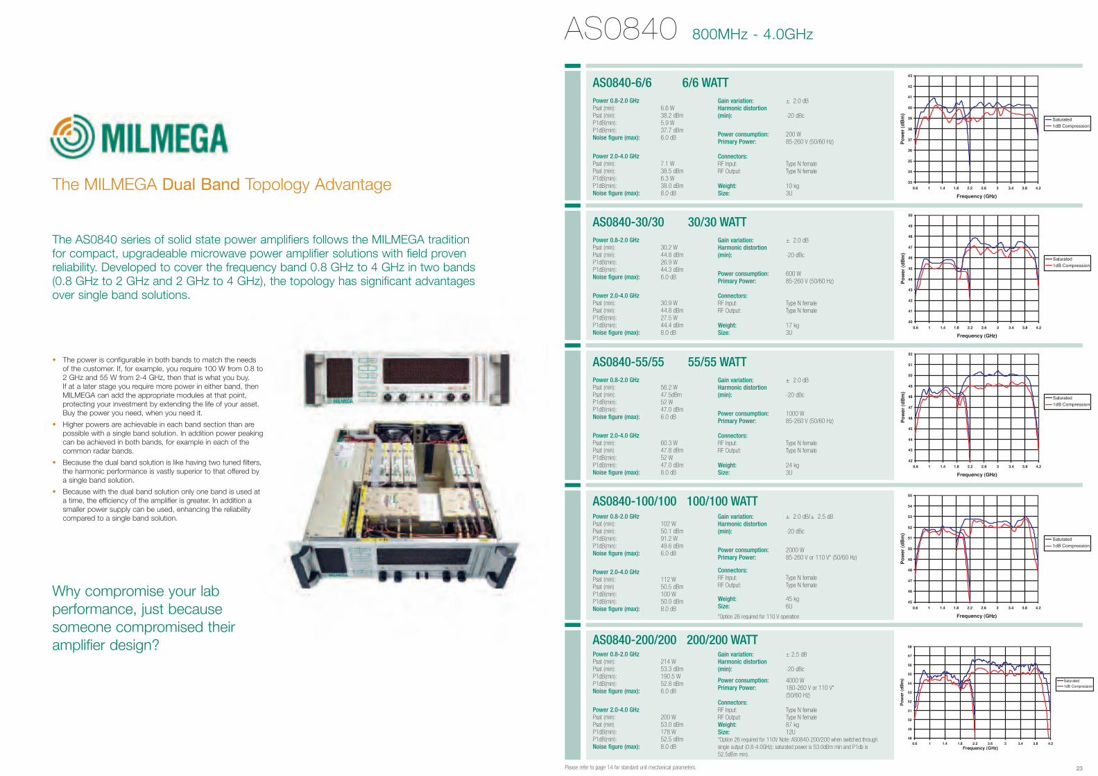
The MILMEGA Dual Band Topology Advantage
23
The AS0840 series of solid state power amplifiers follows the MILMEGA traditionfor compact, upgradeable microwave power amplifier solutions with field provenreliability. Developed to cover the frequency band 0.8 GHz to 4 GHz in two bands(0.8 GHz to 2 GHz and 2 GHz to 4 GHz), the topology has significant advantagesover single band solutions.
• The power is configurable in both bands to match the needs of the customer. If, for example, you require 100 W from 0.8 to2 GHz and 55 W from 2-4 GHz, then that is what you buy. If at a later stage you require more power in either band, then MILMEGA can add the appropriate modules at that point, protecting your investment by extending the life of your asset. Buy the power you need, when you need it.
• Higher powers are achievable in each band section than are possible with a single band solution. In addition power peakingcan be achieved in both bands, for example in each of the common radar bands.
• Because the dual band solution is like having two tuned filters, the harmonic performance is vastly superior to that offered by a single band solution.
• Because with the dual band solution only one band is used at a time, the efficiency of the amplifier is greater. In addition a smaller power supply can be used, enhancing the reliability compared to a single band solution.
Why compromise your labperformance, just becausesomeone compromised theiramplifier design?
Please refer to page 14 for standard unit mechanical parameters.
AS0840 800MHz - 4.0GHz
Power 0.8-2.0 GHzPsat (min): 6.6 W Psat (min): 38.2 dBmP1dB(min): 5.9 W P1dB(min): 37.7 dBmNoise figure (max): 6.0 dB
Power 2.0-4.0 GHzPsat (min): 7.1 W Psat (min): 38.5 dBmP1dB(min): 6.3 W P1dB(min): 38.0 dBmNoise figure (max): 8.0 dB
AS0840-6/6 6/6 WATTGain variation: ± 2.0 dBHarmonic distortion (min): -20 dBc
Power consumption: 200 WPrimary Power: 85-260 V (50/60 Hz)
Connectors:RF Input: Type N female RF Output: Type N female
Weight: 10 kgSize: 3U
Power 0.8-2.0 GHzPsat (min): 30.2 W Psat (min): 44.8 dBmP1dB(min): 26.9 W P1dB(min): 44.3 dBmNoise figure (max): 6.0 dB
Power 2.0-4.0 GHzPsat (min): 30.9 W Psat (min): 44.8 dBmP1dB(min): 27.5 W P1dB(min): 44.4 dBmNoise figure (max): 8.0 dB
AS0840-30/30 30/30 WATTGain variation: ± 2.0 dBHarmonic distortion (min): -20 dBc
Power consumption: 600 WPrimary Power: 85-260 V (50/60 Hz)
Connectors:RF Input: Type N female RF Output: Type N female
Weight: 17 kgSize: 3U
Power 0.8-2.0 GHzPsat (min): 56.2 W Psat (min): 47.5dBmP1dB(min): 52 W P1dB(min): 47.0 dBmNoise figure (max): 6.0 dB
Power 2.0-4.0 GHzPsat (min): 60.3 W Psat (min) 47.8 dBmP1dB(min): 52 W P1dB(min): 47.0 dBmNoise figure (max): 8.0 dB
AS0840-55/55 55/55 WATTGain variation: ± 2.0 dBHarmonic distortion (min): -20 dBc
Power consumption: 1000 WPrimary Power: 85-260 V (50/60 Hz)
Connectors:RF Input: Type N female RF Output: Type N female
Weight: 24 kgSize: 3U
Power 0.8-2.0 GHzPsat (min): 102 W Psat (min): 50.1 dBmP1dB(min): 91.2 W P1dB(min): 49.6 dBmNoise figure (max): 6.0 dB
Power 2.0-4.0 GHzPsat (min): 112 W Psat (min) 50.5 dBmP1dB(min): 100 W P1dB(min): 50.0 dBmNoise figure (max): 8.0 dB
AS0840-100/100 100/100 WATTGain variation: ± 2.0 dB/± 2.5 dBHarmonic distortion (min): -20 dBc
Power consumption: 2000 WPrimary Power: 85-260 V or 110 V* (50/60 Hz)
Connectors:RF Input: Type N female RF Output: Type N female
Weight: 45 kgSize: 6U
*Option 26 required for 110 V operation
Power 0.8-2.0 GHzPsat (min): 214 W Psat (min): 53.3 dBmP1dB(min): 190.5 W P1dB(min): 52.8 dBmNoise figure (max): 6.0 dB
Power 2.0-4.0 GHzPsat (min): 200 W Psat (min) 53.0 dBmP1dB(min): 178 W P1dB(min): 52.5 dBmNoise figure (max): 8.0 dB
AS0840-200/200 200/200 WATTGain variation: ± 2.5 dBHarmonic distortion (min): -20 dBc
Power consumption: 4000 WPrimary Power: 180-260 V or 110 V*
(50/60 Hz)Connectors:RF Input: Type N female RF Output: Type N female Weight: 87 kgSize: 12U*Option 26 required for 110V Note: AS0840-200/200 when switched throughsingle output (0.8-4.0GHz): saturated power is 53.0dBm min and P1db is52.5dBm min).
24 25
AS08110 8.0GHz - 11.0GHz AS08110 8.0GHz - 11.0GHz
Please refer to page 14 for standard unit mechanical parameters.Please refer to page 14 for standard unit mechanical parameters.
Power Psat (min): 4 W Psat (min): 36.0 dBmP1dB(min): 3.6 W P1dB(min): 35.5 dBm
Noise figure (max): 12.0 dBGain variation: ± 4.0 dBHarmonic distortion (min): -20 dBc
AS08110-4 4 WATT
Power consumption: 200 WPrimary Power: 85-260 V (50/60 Hz)
Connectors:RF Input: Type N female RF Output: Type N female
Weight: 14 kgSize: 3U
Power Psat (min): 4 W Psat (min): 36.0 dBmP1dB(min): 3.6 W P1dB(min): 35.5 dBm
Noise figure (max): 12.0 dBGain variation: ± 4.0 dBHarmonic distortion (min): -20 dBc
AS08110-4L 4 WATT
Power consumption: 100 WPrimary Power: 85-260 V (50/60 Hz)
Connectors:RF Input: Type N female RF Output: Type N female
Weight: 6 kgSize: Lab model A
Power Psat (min): 7.9 W Psat (min): 39.0 dBmP1dB(min): 7.1 W P1dB(min): 38.5 dBm
Noise figure (max): 12.0 dBGain variation: ± 2.0 dBHarmonic distortion (min): -20 dBc
AS08110-8 8 WATT
Power consumption: 300 WPrimary Power: 85-260 V (50/60 Hz)
Connectors:RF Input: Type N female RF Output: Type N female
Weight: 14 kgSize: 3U
Power Psat (min): 7.9 W Psat (min): 39.0 dBmP1dB(min): 7.1 W P1dB(min): 38.5 dBm
Noise figure (max): 12.0 dBGain variation: ± 4.0 dBHarmonic distortion (min): -20 dBc
AS08110-8L 8 WATT
Power consumption: 200 WPrimary Power: 85-260 V (50/60 Hz)
Connectors:RF Input: Type N female RF Output: Type N female
Weight: 6 kgSize: Lab model A
Power Psat (min): 15.1 W Psat (min): 41.8 dBmP1dB(min): 13.5 W P1dB(min): 41.3 dBm
Noise figure (max): 12.0 dBGain variation: ± 4.0 dBHarmonic distortion (min): -20 dBc
AS08110-15 15 WATT
Power consumption: 300 WPrimary Power: 85-260 V (50/60 Hz)
Connectors:RF Input: Type N female RF Output: Type N female
Weight: 15 kgSize: 3U
Power Psat (min): 30.2 W Psat (min): 44.8 dBm*P1dB(min): 26.9 W P1dB(min): 44.3 dBm*
Noise figure (max): 12.0 dBGain variation: ± 4.0 dBHarmonic distortion (min): -20 dBc
AS08110-30 30 WATT
Power consumption: 500 WPrimary Power: 85-260 V (50/60 Hz)
Connectors:RF Input: Type N female RF Output: Type N female
Weight: 15 kgSize: 3U
Power Psat (min): 54.6 W Psat (min): 47.4 dBm*P1dB(min): 49 W P1dB(min): 46.9 dBm*
Noise figure (max): 12.0 dBGain variation: ± 4.0 dBHarmonic distortion (min): -20 dBc
AS08110-55 55 WATT
Power consumption: 1000 WPrimary Power: 85-260 V (50/60 Hz)
Connectors:RF Input: Type N female RF Output: Type N female
Weight: 21 kgSize: 3U
Power Psat (min): 100 W Psat (min): 50.0 dBm*P1dB(min): 89 W P1dB(min): 49.5 dBm*
Noise figure (max): 12.0 dBGain variation: ± 4.0 dBHarmonic distortion (min): -20 dBc
AS08110-100 100 WATT
Power consumption: 2000 WPrimary Power: 85-260 V (50/60 Hz)
Connectors:RF Input: Type N female RF Output: Type N female
Weight: 42 kgSize: 6U
26 27Please refer to page 14 for standard unit mechanical parameters.
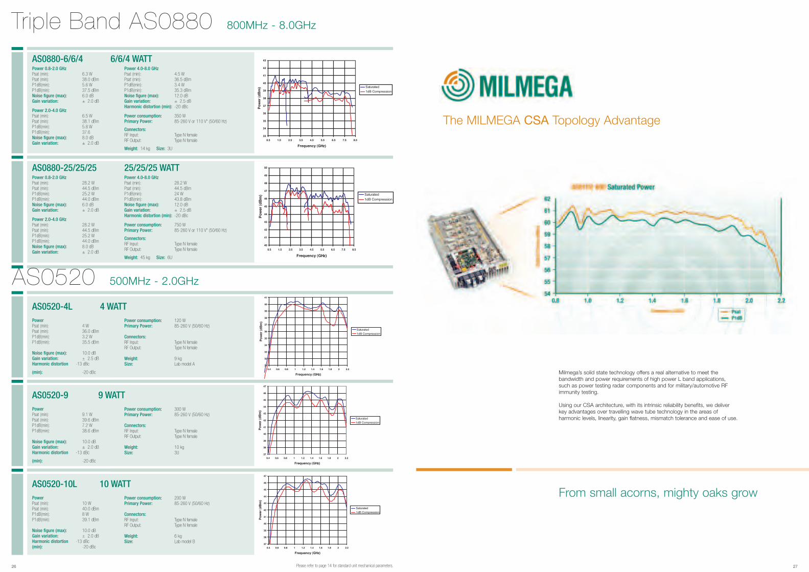
Triple Band AS0880 800MHz - 8.0GHz
Power 0.8-2.0 GHzPsat (min): 6.3 W Psat (min): 38.0 dBmP1dB(min): 5.6 W P1dB(min): 37.5 dBmNoise figure (max): 6.0 dBGain variation: ± 2.0 dB
Power 2.0-4.0 GHzPsat (min): 6.5 W Psat (min): 38.1 dBmP1dB(min): 5.8 W P1dB(min): 37.6Noise figure (max): 8.0 dBGain variation: ± 2.0 dB
AS0880-6/6/4 6/6/4 WATTPower 4.0-8.0 GHzPsat (min): 4.5 W Psat (min): 36.5 dBmP1dB(min): 3.4 W P1dB(min): 35.3 dBmNoise figure (max): 12.0 dBGain variation: ± 2.5 dBHarmonic distortion (min): -20 dBc
Power consumption: 350 WPrimary Power: 85-260 V or 110 V* (50/60 Hz)
Connectors:RF Input: Type N female RF Output: Type N female
Weight: 14 kg Size: 3U
Power 0.8-2.0 GHzPsat (min): 28.2 W Psat (min): 44.5 dBmP1dB(min): 25.2 W P1dB(min): 44.0 dBmNoise figure (max): 6.0 dBGain variation: ± 2.0 dB
Power 2.0-4.0 GHzPsat (min): 28.2 W Psat (min): 44.5 dBmP1dB(min): 25.2 W P1dB(min): 44.0 dBmNoise figure (max): 8.0 dBGain variation: ± 2.0 dB
AS0880-25/25/25 25/25/25 WATTPower 4.0-8.0 GHzPsat (min): 28.2 W Psat (min): 44.5 dBmP1dB(min): 24 W P1dB(min): 43.8 dBmNoise figure (max): 12.0 dBGain variation: ± 2.5 dBHarmonic distortion (min): -20 dBc
Power consumption: 750 WPrimary Power: 85-260 V or 110 V* (50/60 Hz)
Connectors:RF Input: Type N female RF Output: Type N female
Weight: 45 kg Size: 6U
AS0520 500MHz - 2.0GHz
Power Psat (min): 4 W Psat (min): 36.0 dBmP1dB(min): 3.2 W P1dB(min): 35.5 dBm
Noise figure (max): 10.0 dBGain variation: ± 2.5 dBHarmonic distortion -13 dBc
(min): -20 dBc
AS0520-4L 4 WATTPower consumption: 120 WPrimary Power: 85-260 V (50/60 Hz)
Connectors:RF Input: Type N female RF Output: Type N female
Weight: 9 kgSize: Lab model A
Power Psat (min): 9.1 W Psat (min): 39.6 dBmP1dB(min): 7.2 W P1dB(min): 38.6 dBm
Noise figure (max): 10.0 dBGain variation: ± 2.0 dBHarmonic distortion -13 dBc
(min): -20 dBc
AS0520-9 9 WATTPower consumption: 300 WPrimary Power: 85-260 V (50/60 Hz)
Connectors:RF Input: Type N female RF Output: Type N female
Weight: 10 kgSize: 3U
Power Psat (min): 10 W Psat (min): 40.0 dBmP1dB(min): 8 W P1dB(min): 39.1 dBm
Noise figure (max): 10.0 dBGain variation: ± 2.0 dBHarmonic distortion -13 dBc(min): -20 dBc
AS0520-10L 10 WATTPower consumption: 200 WPrimary Power: 85-260 V (50/60 Hz)
Connectors:RF Input: Type N female RF Output: Type N female
Weight: 6 kgSize: Lab model B
The MILMEGA CSA Topology Advantage
From small acorns, mighty oaks grow
Milmega’s solid state technology offers a real alternative to meet thebandwidth and power requirements of high power L band applications,such as power testing radar components and for military/automotive RFimmunity testing.
Using our CSA architecture, with its intrinsic reliability benefits, we deliverkey advantages over travelling wave tube technology in the areas ofharmonic levels, linearity, gain flatness, mismatch tolerance and ease of use.
28 29
OptionsMILMEGA have put together a list of options available within the Series2000 solid state amplifier range. The options range has been designed toaccommodate maximum flexibility when configuring an amplifier system.
Option 1 IEEE/RS232 control (1U high)
Option 1a ACOO2 Ethernet/USB/RS232 internally fitted control
Option 2a Front panel RF sample port SMA-f for a single band unit (SMA-f)
Option 2b Front panel RF sample port SMA-f for a dual band unit. (SMA-f)
Option 3a Front panel RF sample port N-type-f for a single band unit (N-type-f)
Option 3b Front panel RF sample port N-type-f for a dual band unit (N-type-f)
Option 4a Front panel detected sample port SMA-f for a single band unit (SMA-f)
Option 4b Front panel detected sample port SMA-f for a dual band unit (SMA-f)
Option 5a Rear panel RF sample port SMA-f for a single band unit (SMA-f)
Option 5b Rear panel RF sample port SMA-f for a dual band unit (SMA-f)
Option 6a Rear panel RF sample port N-type-f for a single band unit (N-type-f)
Option 6b Rear panel RF sample port N-type-f for a dual band unit (N-type-f)
Option 7a Rear panel detected sample port SMA-f for a single band unit (SMA-f)
Option 7b Rear panel detected sample port SMA-f for a dual band unit (SMA-f)
Option 8 Rear panel RF i/p o/p ports N-type-f (N-type-f)
Option 8a Rear panel dual RF i/p (SMA-f) o/p ports N type-f (N type-f)
Option 9 Preamplifier 10dB
Option 10 Preamplifier 20dB
Option 14 Rack sliders (adds 1U)
Option 15 Dual i/p o/p ports
Option 16 Dual i/p ports only, for dual band amplifiers
Option 17 Dual i/p ports only, for dual band amplifiers
Option 18 Fault slaving
Option 19 Invert logic IEEE
Option 20 Dual amps both on
Option 21 Mains distribution box (1U high)
Option 22 Bench case
Option 23 High speed fans
Option 24 Temperature dependant variable speed fans
Option 26 110V Power supply for high power models
Option 27 Gain control
Option 28 Muting
Option 29 Pre-amp switching
Additional variants may also be possible, at additional cost and delivery time.Please contact the MILMEGA factory for more information.
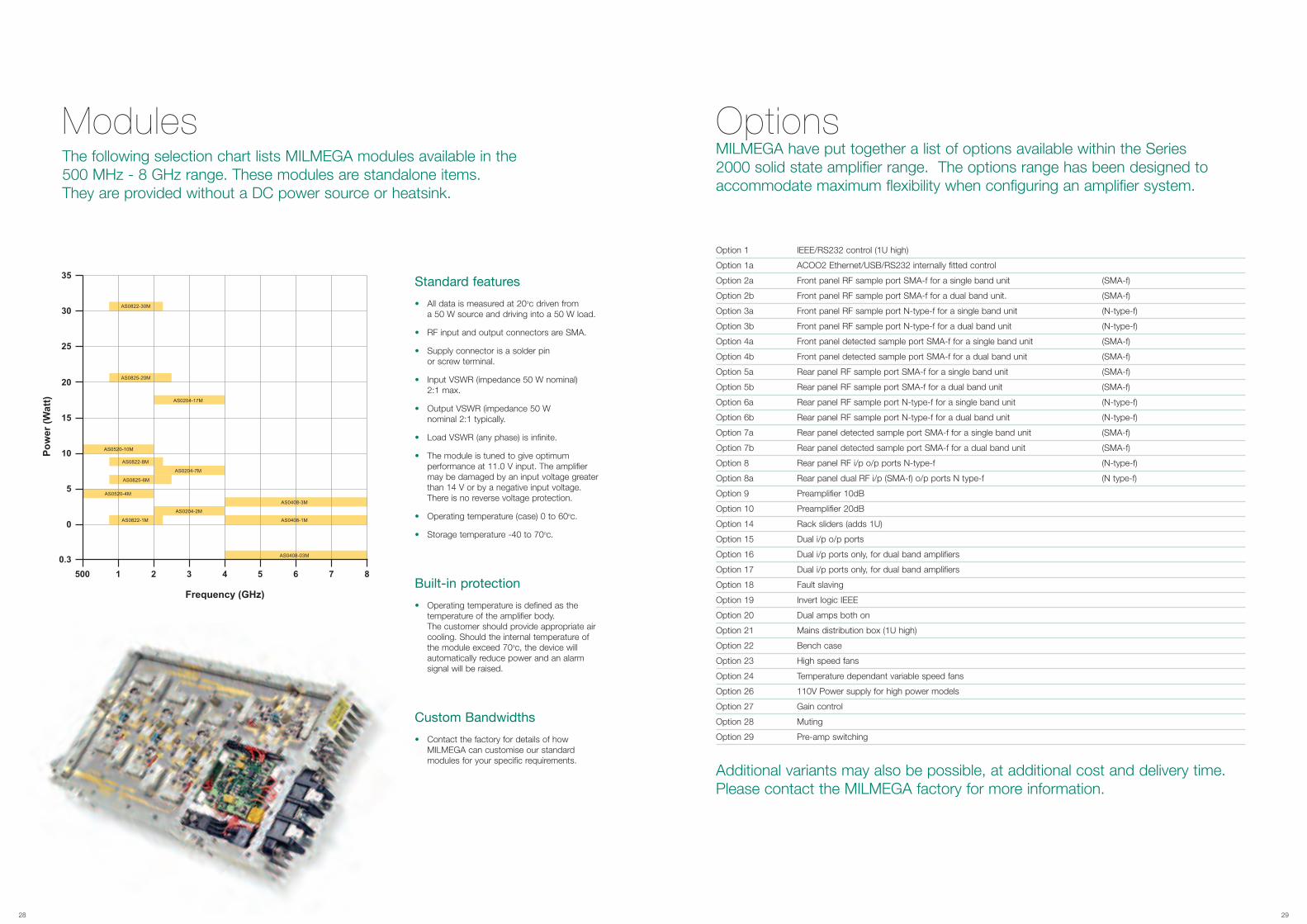
ModulesThe following selection chart lists MILMEGA modules available in the500 MHz - 8 GHz range. These modules are standalone items.They are provided without a DC power source or heatsink.
Standard features
• All data is measured at 20oc driven froma 50 W source and driving into a 50 W load.
• RF input and output connectors are SMA.
• Supply connector is a solder pinor screw terminal.
• Input VSWR (impedance 50 W nominal)2:1 max.
• Output VSWR (impedance 50 Wnominal 2:1 typically.
• Load VSWR (any phase) is infinite.
• The module is tuned to give optimum performance at 11.0 V input. The amplifier may be damaged by an input voltage greater than 14 V or by a negative input voltage. There is no reverse voltage protection.
• Operating temperature (case) 0 to 60oc.
• Storage temperature -40 to 70oc.
Built-in protection
• Operating temperature is defined as the temperature of the amplifier body. The customer should provide appropriate air cooling. Should the internal temperature ofthe module exceed 70oc, the device will automatically reduce power and an alarm signal will be raised.
Custom Bandwidths
• Contact the factory for details of how MILMEGA can customise our standard modules for your specific requirements.

MILMEGA RFCalcMILMEGA RFCalc is a software calculator specifically designed for RFengineers. RFCalc incorporates all the functions one would expect to find in aMicrosoft Window© type calculator with a multitude of features and functionswhich RF engineers utilise every day. Please call MILMEGA for a free copy.
Application notesWe have a number of application notes covering issues related to themicrowave amplifier industry written by our ‘experts in the field’. The notes can either be sent to you electronically or by hard copy. Please call for details.
DatasheetsDatasheets covering all technical data and feature information areavailable to download from our website.
MILMEGA on the World Wide WebVisit our website at www.milmega.co.uk.
Worldwide AgentsMILMEGA offers worldwide support through an extensive networkof approved distributors, ensuring we can deliver the advice andtechnical back up you need to address all your amplifier needs.
Please contact MILMEGA for detailsof your local representative.
MILMEGA Support Material
30 ISSUE 19/07/05 31