Embed Size (px)
Citation preview
technische universiteit eindhoven
Section of Infonnation and Communication Systems (ICSIEB)Faculty of Electrical Engineering
ICSIEB 732
Master's Thesis
Designing a communicationhardware architecture
based on TCPIIP protocol suit
V. Darbroodi
Coach:Supervisor:Period:
prof.ir. M.P.J. Stevensprof.ir. M.P.J. StevensMarch 1999 - January 2000
The Faculty of Electrical Engineering of the Eindhoven University of Technology does notaccept any responsibility regarding the contents of Master's Theses

Contents:
I.IntroductionIntroductionBackground2.Internet structure
2.1.0S1 and TCPIIP stacks2.2.TCP/IP2.3.IP2.3.1.IPv42.3.2.IPv62.3.2.1.IPv6 Extension Headers2.3.3.Difference between two IP header versions2.4.Transport Protocols2.4.1.TCP2A.2.UDP2A.3.difference between UDP and TCP3.Design3.1.Formulation of a problem3.2.Demands3.3.Approach methodImplementation4.Networking4.1.Introduction4.2.The socket programming interfaceIntroduction4.3.Socket structure4.4.Socket buffers4.5.Write system calls4.6.Read system calls5.IP: Internet protocol5.2.Input Processing5.3.0utput Processing5.4.Internet checksum6.IP option processing7.Memory Buffer8.Protocol control blocks9.UDP: User Datagram Protocol9.1.UDP header9.2.System initialization9.3.UDP output9A.UDP checksum calculation and pseudo header9.5.UDP input10.Interface layer10.I.Introduction10.2.ifaddr structure1O.3.sockaddr structure10A.ifnet and ifaddr specialization10.5.Network Initialization
1-2
347899910101111
121213
15
17-1921-242525-262728-3132-3333-343435-3637-3940-41
42-4344444546-47
48-5051525253

10.6.Ethernet initializationII.TCP: Transmission Control Protocol11.I.Introduction11.2.TCP header11.3.TCP control block11.4.TCP state transition diagram11.5.TCP initialization11.6.set initial send sequence number (ISS)12.TCP timers12.1.Introduction12.2.tepJasttimo function12.3.tep_timers function12.4.Presist timer12.5.Connection establishment and keep alive timers12.6.retransmission timer calculations12.7.tep_newteppeb function12.8 .tep_setpresist function12.9.tep_xmiCtimer function12. 10.Summary13.TCP output13.1.Introduction13.2.determine if a segment should be sent13.3.TCP options13.4.Window scale option13.5.Timestamp option13.6.Send a segment14.TCP output14.1.Introduction14.2.Preliminary processing14.3.tep_dooptions function14.4.Header prediction14.5.TCP input: slow path processing14.6.ACK processing14.7.Fast retransmit and fast recovery algorithms15.ICMP: Internet Control Message Protocol15.1.Introduction15.2.ICMP structure15.3.Input processing: iemp_input function15.4.Error processing15.5.Request Processing15.6.Timestamp query15.7.Address mask query15.8.Redirect processing15.9.Reply processing15.10.0utput processing16.conclusionBibliography
53
5657-596061-626363
64656667686869696970
707171727373
74-75757676767677
787879-808182828383848486
ii

Summary
Recent years have seen an unprecedented increase in the number and diversity ofcommunication and telecommunication tools and explosion of new technologies in digitalcommunication and networking used for individual, industrial and commercial purposes.Sources like Personal computers and networking between them, mobile cellular phones andother equipment used in industry, medicine and commerce.All these technologies have made our life richer and easier. Modern society is inconceivablewithout computers. Mobile phones have greatly enhanced the ability of individuals tocommunicate with each other and have facilitated the dispatch of emergency medical andpolice aid to persons in both urban and rural environments.These new technologies gave us new definitions like Internet, WWW.MP3 and etc.After all said and done we want to push the envelope even further and try to have theadvantages of the mobility and connectivity that is given to us in any place and any time.Therefore this is only. the only next reasonable step to try to find a solution to make it morereliable and as result even faster.Here is when our design comes in:
Designing a hardware structure for a communication system based onTCPIIP protocol suit.

I.IntroductionIn the early days of computing, hosts exchanged information with directly attached devices,such as card reader and printers. Interactive use of computers first required local and theremote attachment of end-user terminals.When an organization had acquired several computers, often there would be a need to transferdata between computers or to allow users attached to one computer to access anothercomputer.Computer vendors responded to these requirements by developing communications hardwareand software. Unfortunately, this hardware and software:
• Was proprietary and worked only with the vendor's equipment• Supported only a limited number of local and wide area network types• Sometimes was extremely complex, requiring different software dialects for each device
and each application• Lacked the flexibility that would enable previously independent networks to be connected
to each other easily and inexpensivelyThis situation changed with the help of Transmission Control Protocol/Internet Protocol(TCPIIP) and the router technology that it spawned.Today, an organization's computer network has become its circulatory system. Organizationshave combined desktop workstations, servers, and hosts into Local Area Network (LAN)communities. They have connected LANs to other LANs and to Wide Area Network (WANs).It has become a necessity of day-to-day operation that pairs of systems must be able tocommunicate when they need to, without regard for where they may be located in the network.
TCPIIP APPLICATIONS
From the beginning, TCPIIP was packaged with several important generic applicationservices:
• Terminal access to any host• The ability tb copy files from one host to another• Exchange of electronic mail between any pair of users
Over the years, many other useful applications have been added to the TCPIIP protocol suite:
• Remote Printing• Network File system• Network News• Gopher• The World Wide Web (WWW)
In addition, the set of utilities that support network administration and maintenance has beenexpanding.
A few are:
• Directory services for mapping user-friendly host names to network addresses
1

• Dynamic Host Configuration• Network Management for host, routers, and other network devices
The TCPIIP family is alive, well, and growing. Its user community is expanding at an almostexplosive rate, and new services are being developed and modularly integrated into TCPIIPproduct offerings.
2

2.Internet structure
The TCP/IP protocol suite allows computers of all sizes, from many different computervendors, running totally different operating systems, to communicate with each other. It isquite amazing because its use far exceeded its original estimates. What started in the late1960s as a government-financed research project into packet switching networks has, in the1990, turned into the most widely used form of networking between computers.
2.1.081 and TCP/IP stacks
In order to achieve a reliable exchange of data between computers, there are many separateprocedures that must be carried out:• Package the data• Determine the path that the data will follow• Transmit the data on a physical medium• Regulate the rate of data transfer according to the available bandwidth and the capacity of
the receivers to absorb data• Assemble incoming data so that it is in sequence and there are no missing pieces• Handle error or problem eventsThe specific structure selected for the TCP/IP protocols was dedicated by requirements thatevolved in the academic and defense communities. IP does what is needed to glue differenttypes of networks into an Internet. TCP provides reliable data transfer.The OSI data communications model was strongly influenced by TCP/IP's design. OSIlayering and OSI terminology have become a standard [part of the data communicationsculture.
Figure 2.1 shows the TCP/IP and OSI layers.
3

APPLICATIONSANDSER V ICES
TCP UDP
IP
DATA LINK
PHYSICAL
T C P lIP
FIGURE 2.1. TCPIIP and OSI layers
2.2.TCP/IP
APPLICATIONSAND SERVICES
PRESENTATION
SESSION
TRANSPORT
NETWORK
DATA LINK
PHYSICAL
o S I
Networking protocols are normally developed in layers, with each layer responsible for adifferent facet of the communications. A protocol suite, such as TCPIIP, is the combination ofdifferent protocols at various layers. TCP/IP is normally considered to be a 4- layer system, asshown in figure 2.2.
4

IAPPLICATION
TRANSPORT
NETWORK
LINK
Telnet, FTP,e-mail,etc.
TCP,UDP
IP, ICMP, IGMP
device driver andinterface card
The four layer of theTCP/IP PROTOCOLSUITE
Figure 2.2.TCPIIP
Each layer had a different responsibility:
1. The link layer, sometimes called the data-link layer or network interface layer, normally ithandles all the details of physically interfacing with whatever type of media is being used.
2. The network layer (Internet layer) handles the movement of packets around the network.Routing or packets, for example, takes place here.
3. The tranposrt layer provides a flow of data between two hosts, for the application layerabove.
4. The application layer handles the details of the particular application.
There are more protocols in the TCPIIP protocol suite. Figure 2.3 shows some of theadditional protocols that we talk about in this text.
5

TRANSPoRT
USERPROCESS
UDP
USERPROCESS
TCP
I USERPROCESS
~NET
ICMP IP IGMP W0RK
USERPROCESS
APPELICATIoN
ARP
HARDWAREINTERFACE
RARP
LINK
MEDIA
Figure 2.3. VARIOUS PROTOCOLS AT THE DIFFERENT LAYERIN THE TCPIIP PROTOCOL SUITE
6

TCP and UDP are the two predominant transport layer protocols. Both use IP as the networklayer.TCP provides a reliable transport layer, even though the service it uses (IP) is unreliable.UDP sends and receives datagrams for applications. A datagram is a unit of information thattravels from the sender to the receiver. Unlike TCP, however, UDP is unreliable.IP is the main protocol at the network layer. It is used by both TCP and UDP. Every piece ofTCP and UDP data that gets transferred around an internet goes through the IP layer at bothend systems and at every intermediate router.
ICMP is an adjunct to IP. It is used by the IP layer to exchange error messages and other vitalinformation with the IP layer in another host or router.IGMP is the Internet group management protocol. It is used with multicasting: sending a UDPdatagram to multiple hosts.
ARP (Address Resolution Protocol) and RARP (Reverse Address Resolution Protocol) arespecialized protocols used only with certain types of network interfaces (such as Ethernet andtoken ring) to convert between the address used by the IP layer and the addresses used by thenetwork interface.
2.3.IP
IP is the workhorse protocol of the TCPIIP protocol suite. All TCP, UDP, ICMP, AND IGMPdata gets transmitted as IP datagrams (figure 2.3).IP provides an unreliable, connectionless datagram delivery system.The term connectionless means that IP does not maintain any state information aboutsuccessive datagrams. Each datagram is handled independently from all other datagrams. Thisalso means that IP datagrams can get delivered out of order. If a source sends two consecutivedatagrams (first A, then B) to the same destination, each is routed independently and takedifferent routes, with B arriving before A.The most significant bit is numbered 0 at the left, and the least significant bit of a 32-bit valueis numbered 31 on the right.The 4 bytes in tpe 32-bit value are transmitted in the order: bits 0-7 first, then bits 8-15, then16-23, and then 24-31 last.This is called big endian byte ordering, which is the byte ordering required for all binaryintegers in the TCPIIP headers as they traverse a network.
7

2.3.1.IP v4
The following is a representation of the IPv4 header.
o 1516 32
4-bit 4-bit 8-bit type of 16-bit total lengthversion header service
16-bit identification 3-bit 13-bit fragment offsetflags
8-bit time to live 8-bit protocol 16-bit header checksum
32-bit source IP address
32 bit destination IP address
Options ( if any)
Data
Figure 2.4. IP header
The current protocol version is 4, so IP is sometimes called IPv4. In the next chapter we willdiscuss about the next generation IP or IPv6.
8

2.3.2.IPV6
The following is a representation of the IPv6 header.
version IPriority I Flow label
Payload length Next header Hop Limit
Source address
Destination address
Figure2.5. IPV6 header
2.3.2.1.IPv6 Extension Headers
In IPv6, optional Internal-layer is information is encoded in separate headers that may beplaced between the IPv6 header and the upper layer header in a packet.There are a small number of such extension headers; each identified by a distinct Next Headervalue.
2.3.3.Difference between two IP header versions
IP version 6 (IPv6) is a new version of the Internet protocol designed as a successor to IPversion 4 (IPv4) [RFC-791]. The changes from IPv4 to IPv6 fall primarily into the followingcategories:• Expanded addressing capabilities IPv6 increases the IP address size from 32 bits to 128bits, to support more levels of addressering hierarchy, a much greater number of addressablenodes, and simpler auto-configuration of addresses.• Header formats simplification some IPv4 header fields have been dropped or madeoptional.• Improved support for extensions and options changes in the way IP header options areencoded allows for more efficient forwarding, less stringent limits on the length of options,and the greater flexibility for introducing new options in the future.• Flow labeling capability a new capability is added to enable the labeling of packets
belonging to particular traffic "flows".
9
• Authentication and privacy capabilities Extensions to support authentication, dataintegrity, and data confidentiality are specified for IPv6.
2.4.Tranport protocols
As we know TCP and UDP are the two predominant transport layer protocols. Both use IP asthe network layer.TCP provides a reliable transport layer, even though the service it uses (IP) is unreliable.UDP sends and receives datagrams for applications. A datagram is a unit of information thattravels from the sender to the receiver. Unlike TCP, however, UDP is unreliable.IP is the main protocol at the network layer. It is used by both TCP and UDP. Every piece ofTCP and UDP data that gets transferred around an internet goes through the IP layer at bothend systems and at every intermediate router.
2.4.1.TCP
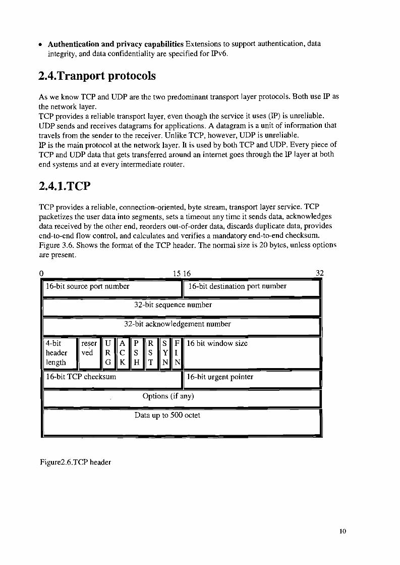
TCP provides a reliable, connection-oriented, byte stream, transport layer service. TCPpacketizes the user data into segments, sets a timeout any time it sends data, acknowledgesdata received by the other end, reorders out-of-order data, discards duplicate data, providesend-to-end flow control, and calculates and verifies a mandatory end-to-end checksum.Figure 3.6. Shows the format of the TCP header. The normal size is 20 bytes, unless optionsare present.
o 15 16 32
I16-bit source port number I 16-bit destination port number
32-bit sequence number
I32-bit acknowledgement number I
4-bittJ~~~~~~16 bit window s~e Iheader
length G K H T N N
I16-bit TCP checksum 1·16-bit urgent pointer
Options (if any)
Data up to 500 octet
Figure2.6.TCP header
10

2.4.2.UDP
UDP is a simple protocol. Its official specification, RFC 768 [Postel 1980], requires only threepages. The services it provides to a user process, above and beyond IP, are part numbers andan optional checksum.Figure 3.7. Show the fields in the UDP header.
o16-bit source port number
16-bit UDP length
Figure2.7. UDP header
1516
16-bit destination port number
16-bit UDP checksum
Data ( if any)
32
2.4.3.difference between UDP and TCP
The TCP is. Like UDP, a transport layer protocol. However, whereas UDP is a fairly simpleand straightforward protocol offering very little in the way of reliability or guarantees, TCPprovides a way to connect hosts across an Internet work reliability. UDP's unit of exchange isthe UDP datagram, a stand-alone message; TCP packages its data into segments containingboth data and session control information.Whereas UDP is connectionless, TCP connections are virtual circuits, acting as if there is adirect, two-way connection between the two communicating hosts. Whereas UDP isunreliable, TCP provides end-to-end reliability, requiring that communicating hosts coordinateand agree to make connections and acknowledge receipt of network traffic. Whereas eachUDP datagram stands by itself as an individual message or reply, TCP supports out-of-orderdelivery of segments, reassembling data streams from IP datagrams that have been deliveredout of order.
TCP is differentiated from UDP in three basic ways:
• virtual circuits• Reliable connections• Performance optimization
11

3.Design
3.1. Formulation of a problem
The concept of our design is to be able to communicate with other systems with the use ofInternet protocol.There are different kind of protocol suites and IP stack in particularly are built of differentlayers and as we can see it in the figure 3.1 IP protocol stack's got four layers. Our goal isto design and realization of a communication route between two separate stations. Thestations can be hosts, servers, bridges, and etc.In our design we cover the whole protocol stack from application (through the kernel) tothe Network interface layer (and for example we will discuss Ethernet to certain level).
APPLICATION
TRANSPORT
NETWORK
LINK
Telnet, FTP,e-mail,etc.
TCP,UDP
IP, ICMP, IGMP
device driver andinterface card
The four layer of theTCP/IP PROTOCOLSUITE
FIGURE 3.1. IP protocol stacks
To have a global idea about what and how our design would and should be I suggest takinga quick look at the figure 2.2.
3.2. Demands
The demands are the same demands for any other system:
• Properly works• manufacturability• cost efficiency• easy to upgrade• The ability to work independently on any Hardware or Software platform.
12

3.3. Approach method
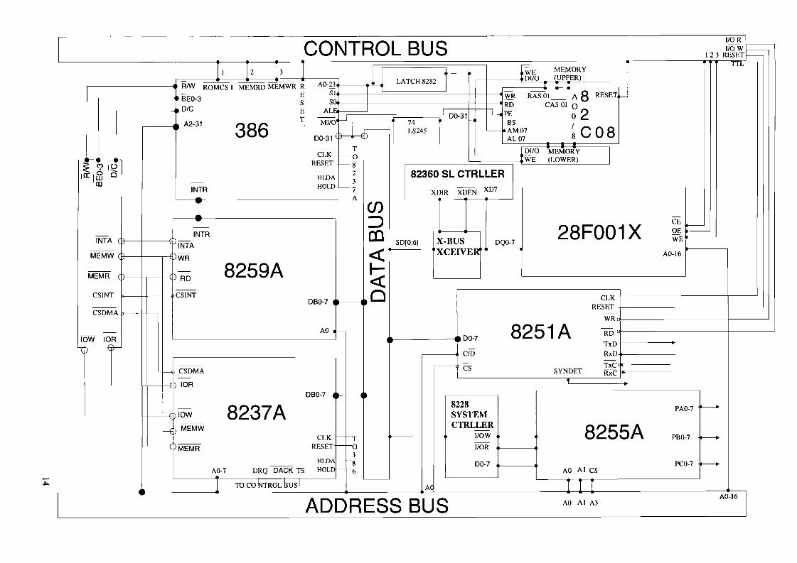
the first step is to build a foundation for the design.That is the hardware needed to be able to run the embedded software that is needed toachieve the goal and completing the mission.Our system includes:
• CPUWe use an Intel 80386.The first design was with a 8080 but because of the fact that those are not in the marketanymore (the manufacturability factor) we switched to 80386. It's satisfactory to the needsof our design.
• Programmable peripheral interface: 8255A Intel
• Interrupt controller: 8259 A Intel
• DMA controller: 8237A Intel
• Programmable communication interface: 825lA Intel
• RAM(controller) : 82c08 Intel
It is compatible with our CPU and we can according to our need expand the amount ofRAM we need.
• ROM(controller) : 28FOOIBX IntelThis is a Flash ROM controller.The amount of memory that we need depends on the kernel and how much memory wouldkernel need to operate the system.
This is a basic set up and it can be expanded or minimized by using a all on-one chip set.For the specification and technical notes about the Hardware components please contact Intelcorporation.Next step is the software part that we need to be able to do the job:
13
ICONTROL BUS 110 R I
1I0W.~123 RESET
II 12 h I 111 MEMORY
I
TTl:""WE
~ -~----- AO-23 LATCH 8282 I DIIO (UPPER)
RNY ROMCS I MEMRO MEMWR R l'
BEO-3E SI WR RASOI_ A8 RESETS S"·
t---J
DIG ALrRO CAS 01 0
ET ~I
00-31 L-. PE 02A2-31 386 MilO
~174 BSLS245 - ~AM07 ~C0800-31 AL07
T 0110 MEMORYICLK -0
~ C') 10RESET -8
WE (LOWER)
\ IEi3 Q HillA 2 82360 SL CTRLLERIII - -3
INTR HOLD f--- 7 XDEN XD7A
XOIR
I en- :::> -
- 28FOO1XCE
l>-----
-1
INTR (Q OE~INTA
INTA SO[0:61 X·BUS DQO-7 WE
--MEMW 'WR « XCEIVEK AO-16
-- - 8259A ~MEMR RD
-- --CSINT CSINT 0DBO-7
CLK-- RESETCSDMA -
WR
- - AO •I-- 8251A -
lOW lOR 00-7RO
ljJ -TxD
C/D RxD
-- ~- -
- CSDMA CS TxC
-SYNDET RxC
lOR •DBO-7
- 8237A 8228 '----lOW SYSTEM
PAO-7
-- CTRLLER4 ) MEMW - 8255ACLK I---. 1I0W PBO-7 0--------.
MEMR RESET - -0 1I0R3
HLDA~ -8-- HOLD00-7 PCO-7 0--------.
AO-7 DRQ DAGK TS - f---6 AO AI CS-1 TO CO l-HROL BUS I
"----------J
Ad TIT
I ADDRESS BUS AO AI A3 AO-16 I

Implementation
4.Networking
4.1.Introduction
The networking code in the kernel is organized into three layers:
1. The Socket layer is a protocol-independent interface to the protocol- dependent layerbelow. All system calls start at the protocol-independent socket layer.
2. The protocol layer contains the implementation of the four most common protocolfamilies.
3. The interface layer contains the drivers that communicate with the network devices.
nnect, etc.)
ProcessI
A
system calls (socket, bind, co
Socket layer
protocol layer
(TCP/IP, OSI, XNS, UNIX)
inetrface layer
(Ethernet, SLIP, etc.)
Media
Figure4.1. The general organization of networking code
15

Socket layer:
application
function call
socket system calls
system callprocesskernel- - - -
socket system callimplementation
function call
socket layerfunctions
calls via pr_usrreq or pr_ctloutput
Figure 4.2. The socket layer converts generic requests to specific protocol operations
16

4.2.The socket programming interface
Introduction
The communications standards define all of the rules needed to exchange data across anetwork. However, until recently, the need to standardize application programming interface(APls) for communication has been ignored. How can a programmer write a client/serverapplication if the programs are completely different on every computer?
4.2.l.Berkeley Programming Interface
Fortunately, most TCPIIP implementations offer a programming interface that follows a singlemodel, the socket programming interface. The socket programming interface was firstintroduced with the 1982 4.1 c Berkeley software distribution (BSD) version of the Unixoperating system. A number of improvements have been incorporated into the originalinterface over time.The socket programming interface was designed for use with several communicationsprotocols, not for TCPIIP alone. However, when the OSI transport layer specification wascompleted, it was clear that the socket interface was not general enough to satisfy OSIrequirements.In 1986, AT&T introduced the Transport Layer Interface (TLI) for Unix system V. the TLI canbe used to interface to the OSI transport layer, TCP, and other protocols.Another important addition to the socket family was the Windows Socket programminginterface, or WinSock. It has enabled Windows applications to run on top of TCPIIP stacksimplemented by many different vendors.The socket interface is a de facto standard because it is almost universally available and is inwide spread use. There will be minor differences in the APls offered on various computers,due to the way that each vendor has implemented communications services within itsoperating system. The manual for the appropriate system should be consulted forprogramming details.
4.2.2.Unix orientation
The original socket interface was written for a Unix operating system. The Unix architectureprovides a framework in which standard file, terminal, and communications I/O all operate ina similar fashion. Operations are performed on a file by means of calls such as:
Descriptor =open (filename, readwritemode)Read (descriptor, buffer, length)Write (descriptor, buffer, length)Close (descriptor)
When a program opens a file, the call creates an area in memory called afile control block.Information about the file, such as its name, attributes, and location, are stored in the filecontrol block.The call returns a small integer called afile descriptor. The program uses this descriptor toidentify the file in any subsequent operations. As the user reads from or writes to the file, apointer in the descriptor keeps track of the current location in the file.
17

A very similar framework is used for TCPIIP socket communications. The primary differencebetween the socket programming interface and the Unix file I/O interface is that a couple ofpreliminary calls are required in order to assemble all of the information that is needed tocarry out communications.Apart from the extra work at setup time, ordinary read and write calls can be used to receiveand send data across a network.
4.2.3.Socket services
STREAM DATAGRAM RAW
TCP UDP
IP
Figure 4.3. Socket application programming interfaces
The socket programming interface provides three TCPIIP services. It can be used for TCPstream communication, UDP datagram communications, and raw datagram submission to theIPlayer.A raw socket allows privileged users direct acces to a protocol.The RAW socket support is built around a generic raw socket interface and the next sectionsdescribe only the core of the raw socket interface.
4.2.4.Blocking and Nonblocking Calls
When a program reads data from a network connection, it is hard to predict how long it willtake before some data arrives and the call can complete. One issue that has to been decided iswhether to wait for the outcome of a read (blocking, or synchronous) or return immediately (nonblocking, or asynchronous) and get the data either by checking a status variableperiodically or by responding to an interrupt.
4.2.S.Socket calls
The socket call prepares for communication by creating a transmission control block (TeB) or"creating a socket".The socket call returns a small integer called a socket descriptor that is used to identify thecommunication in any subsequent operations.A few type of information that is included in the TCB for a TCP session:• Local IP address• Localport
18

• Protocol (e.g., TCP or UDP)• Remote IP address• Remote port address• Send buffer size• Receive buffer size• Current TCP state• Smoothed round-trip time• Smoothed round-trip deviation• Current retransmission timeout value• Number of retransmission that have been sent• Current send window size• Maximum send segment size• Sequence number of last byte that was ACKed• Maximum receive segment size• Sequence number of next byte to be sent• Enable or disable tracing
19

4.2.6.UDP socket programming interface
CLIENT SERVER
.--- SOCKET ()
~-----. SOCKET SCRIPTOR
.--- BIND ()
~ OK
.--- RECVFROM ()
SOCKET () ~
SOCKET SCRIPTOR .---BIND () ~
OK .---
SEND TO () ~ ------. ~ BUFFER OF DATA
RECVFROM ()~
BUFFER OF DATA.--- .---'--- SEND TO ()
CLOSE ()
Figure 4.4. Typical UDP socket calls
Figure above shows an outline of a UDP dialogue between a client and server. The socket ( )and bind ( ) calls complete quickly and have an immediate return.The recvfrom call is assumed to be blocking, which is its normal default.It can be changed to nonblocking (i.e., asynchronous) mode.
20

4.3.S0CKET Structure
A socket represents one end of a communication link and holds or points to all the informationassociated with the link. This information includes the protocol to use, state information forthe protocol (which includes source and destination addresses), queues of arrivingconnections, data buffers, and option flags.
struct socket{short
shortshortshortcaddctstructstructstructstructshortshortshortshortu_shortpid_tu_long
1*
so_type;so_options;so_linger;so_state;so_pcb;protosw *so_proto;socket *so_head;socket *so_qO;socket *so_q;so_qOlen;so_qlen;so_qlimit;so_timeo;so_error;so_pgid;so_oobmark;
**1
variables for socket buffering.
so, caddect arg, ont waitf);(struct socket *
so_rcv,so_tcpb;(*so_upcall)so_upcallarg;
struct sockbuf{u_long sb_cc;
u_long sb_hiwat;u_long sb_mbcnt;u_long sb_lowat;struct mbuf *sb_mb;struct selinfo sb_sel;short sb_flags;short sb_timeo;}
caddctvoidcaddct
Figure 4.5. STRUCT SOCKET definition
21

4.3.l.SYSTEM calls
A process interacts with the kernel through a collection of well-defined functions calledsystem calls.The transfer of execution from a process to the protected environment of the kernel ismachine- and implementation dependent. We use the 386 implementation of NET/3 toillustrate implementation specific operations.
SOCKET
WRITEWRITEVSENDTOSENDMSG
SHUTDOWN
SELECTREADREADVREADFROMREADMSG
CLOSE
Figure 4.6. Network system call flowchart
4.3.l.S0CKET System call
The socket system call creates a new socket and associates it with a protocol as specified bythe domain, type, and protocol arguments specified by the process.
4.3.2.BIND System call
The bind system call associates a local network transport address with a socket.A server process almost always needs to bind to a specific well-known address. If so, theprocess must call bind before accepting connections (TCP) or receiving datagrams (UDP).A socket's foreign address is specified by connect or by one of the write calls that allowspecification of foreign addresses.
22

4.3.3.LISTEN System call
The listen system call notifies a protocol that the process is prepared to accept incomingconnections on the socket. It also specifies a limit on the number of connections that can bequeued on the socket, after which the socket layer refuses to queue additional connectionrequests.Queued connections are made available to the process when it calls accept.
4.3.4.ACCEPT System call
After calling LISTEN, a process waits for incoming connections by calling ACCEPT, whichreturns a descriptor that references a new socket connected to a client.
4.3.5.CONNECT System call
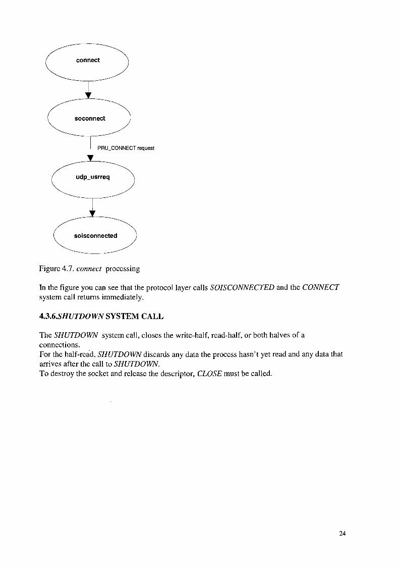
A server process calls the LISTEN and ACCEPT system calls to wait for a remote process toinitiate a connection. If the process wants to initiate a connection itself (Le., a client), it callsCONNECT.For connection-oriented protocols such as TCP, CONNECT establishes a connection to thespecified foreign address.For connectionless protocols such as UDP or TCMP, CONNECT records the foreign addressfor use in sending future datagrams.
23
connect
soconnect
PRU_CONNECT request
Figure 4.7. connect processing
In the figure you can see that the protocol layer calls SOlSCONNECTED and the CONNECTsystem call returns immediately.
4.3.6.SHUTDOWN SYSTEM CALL
The SHUTDOWN system call, closes the write-half, read-half, or both halves of aconnections.For the half-read, SHUTDOWN discards any data the process hasn't yet read and any data thatarrives after the call to SHUTDOWN.To destroy the socket and release the descriptor, CLOSE must be called.
24

4.4.S0CKET BUFFERS
We know that each socket has an asociated send and receive buffer. The SOCKBUF structuredefinition mentioned in struct socket definition is shown in this header:
struct sockbuf{u_long sb_cc;u_long sb_hiwat;u_long sb_mbcnt;u_long sb_lowat;struct mbuf *sb_mb;struct selinfo sb_se1;
short sb_flags;short sb_timeo;} so_rcv,
Figure 4.8. SOCKBUF structure
4.5.WRITE system calls
There are four system calls, we refer to collectively as the write system calls.These four system calls send data on a network connection.All the write system calls, directly or indirectly, call SOSEND, wich does the work of copying
SEND
pcocess _ _ _ _ . _ _ _ _ • • _ _ _ _ _ _ • _ _ _ _ _kernel
WRITESENDTO
SENDIT
SENDMSG
calls via pr_usrreq or pr3t1oulpul
Figure 4.9. Flow of the control for the write system calls
25

data from the process to the kernel and passing data to the protocol associated with the socket.
4.5.l.SENDMSG system call
Only the SENDMSG system call provides access to all the features of the socket APIassociated with output.The sendmsg and sendit functions prepare the data structures needed by sosend, wich passesthe message to the appropriate protocol. For SOCK_DGRAM protocol, a message is adatagram. For a SOCK-STREAM protocols, a message is a sequence of bytes.
4.5.2.SENDIT system call:
SENDIT copies control and address information from the process into the kernel.
4.5.3.S0SEND system call:
SOSEND is one of the most complicated functions in the socket layer. It is SOSEND'sresponsibility to pass the data and control information to the pr_usrreq function of theprotocol associated with the socket according to the semantic supported by the protocol andthe buffer limits specified by the socket. SOSEND never places data in the send buffer; it is theprotocol's responsibility to store and remove the data.
26

4.6.READ system call
There are four systems calls, which we refer to collectively as read system calls, receive datafrom a network connection. The first three system calls are simpler interfaces to the mostgeneral read system call, recvmsg.The read and readv system calls are valid with descriptor, but the remaining calls are validonly with socket descriptors.As with write the write calls, the receive calls utilize a common function, in this casesoreceive, to do all the work.
rscvmsg,.-,sad
. process _
kemel
EJ calls via P,-US"9qor PUtlolApu' 2
Figure 4.10. Flow of the control for the read system calls
4.6.l.RECVMSG system call
The RECVMSG function is the most general read system call. Addresses, control information,and receive flags may-be discrded without notification if a process uses one of the other readsystem calls while this information is pending.
4.6.2.S0RECIVE system call
This function transfers data from receive buffer of the socket to the buffers specified by theprocess.
27

5.IP: INTERNET PROTOCOL
5.1.INTROCUDTION
The IP part starts when a network interface place incoming IP packets in the IP input queue,(ipintrq) and then they schedule a software interrupt. Since hardware interrupts have a higherpriority than software interrupts, several packets may be placed on the queue before a softwareinterrupt occurs. During software interrupt processing, the ipintr function removes andprocesses packets from ipintrq until the queue is empty. At the final destination, IPreassembles packets into datagrams and passes the datagrams directly to the appropriatetransport-level protocol by a function call. If the packets haven't reached their finaldestination, IP passes them to IPJorward if the host is configured to act as a router. Thetransport protocols and IP_FORWARD pass outgoing packets to IP_OUTPUT, whichcompletes the IP header, select an output interface, and fragments the outgoing packet ifnecessary. The resulting packets are passed to the appropriate network interface outputfunction.When and error occurs, IP discrads the packet and under certain conditions may send and errormessage to the source of the original packet. These message are part of ICMP. NET/3 sendsICMP error messages by calling ICMP_ERROR, which accepts an mbuf containing theerroneous packet, the type of error found, and an option code that provides additionalinformation depending on the type of error.
28

transprt protocolUDP, TCP, ICMP, IGMP
/ I IP-----(------ - -~--
ipintr
ipintrq:
-"
network interface
network
Figure 5.1. IP layer processing
5.1.1.IP PACKETS
We call the data passed to IP by a transport protocol a message. A message typically containsa transport header and application data. IP prepends its own header to the message to form adatagram. If the datagram is too large for transmission on the selected network, IP splits thedatagram into several fragments, each of which contains its own IP headr and a portion of theoriginal datagram.An IP fragment or an IP datagram small enough to not require fragmentation are calledpackets when presented to the data-link layer for transmission. The data-link layer prepends itsown header and transmits the resulting frame.
29

MESSAGE
liP IUDP II _-------:-;----_ '"""0'""'0'"
DATAGRAM
IP UDP
packet
FRAGMENT 1
APPLICATIONDATA
i'\PPLICATIONpATA
IP
...
FRAGMENT 3
IP APPLICATION DATA
FRAGMENT 2
Figure 5.2. Packets, fragments, datagrams, and messages
o 1516 31
version Iheader I type of total lengthlength serviceiP3 ip hi ip tos ip_len
identification' flags and fragment offset
ip_id ip_oll
time to live
Iprotocol header checksum
ip_ttl ip_p ip3ksum
32-bit source addressip_src
32-bit destination address
ip_dst
-:: options (if any)f'..r---
data
,I'-
Figure 5.3. IP datagram(header)
5.1.2.IP HEADER FORMAT
20 bytes
VERSION: The version field is used to indicate the format of the IP header.
lliL: lliL stands for Internet header length. It is the length of the Internet header in 32-bitwords, and points to the beginning of data.
TYPE OF SERVICE: Type of service field specifies how the datagram is treated during itstransmission through the network.
30
Total length: this field indicates the total length of the datagram; this includes the IF headerand data.
FLAGS: the FLAG field has three bits. If fragmentation is supported, they are used to indicatenot to fragment, more fragment, and last fragment.
FRAGMENT OFFSET: This is indicates where in the datagram the fragment belongs,assuming fragmentation has occurred.
TIME TO LIVE: This indicates the maximum time a datagram is permitted to stay in theInternet system (whether this is a local Internet or the Internet). When the value equals zero,the datagram is destroyed. Time is measured in units per second, and each entity processes thedatagram must decrease the value by one, even if the process time is less than one second.
PROTOCOL: This field determines whether the data should be sent to TCP or UDP in thenext layer in the network.
HEADER CHECKSUM: This is a header checksum only. Some header fields change, and theheader checksum is recomputed and verified every time the header is processed.
SOURCE ADDRESS: This is the originator of the datagram. It consists of 32 bits.
DESTINATION ADDRESS: This is the target for the header and data. Like the sourceaddress, it too is 32 bits.
OPTIONS: Options mayor may not appear in datagrams. Options must be implemented in IFmodules; they might not be use in any given transmission.A number of variables exit for the OPTIONS field. The following is a list of those variables,including brief explanations:
NO OPTIONS: this option can be used between options to correlate the beginning of afollowing option on a 32-bit boundary.
SECURITY: security is a mechanism used by DoD. It provides hosts a way to use security bymeans of compartmentation, handling restrictions, and transmission control codes (TCC). Thecompartmentation value is used when information transmitted is not compartemented.Handling restrictions are defined by the Defense Intelligence Agency. TCC permitssegregation of data traffic.LOOSE SOURCE and RECORD ROUTE: This provides a way for a source of a datagram tosupply routing information to aid in forwarding the datagram. It also serves to record the routeinformation.
STRICT SOURCE and RECORD ROUTE: This option permits the source of a datagram tosupply information used by routers and record the route information.
RECORD ROUTE: This is simply a way to record the route of a datagram as it traverses thenetwork.
31

lp_sum;ip_src, ip_dst;
STREAM IDENTIFIER: This provides a way for stream identifier to be carried throughnetworks that do not support this stream concept.
TIME STAMP: This option includes a pointer, overflow, flag field, and Internet addresses.Simply put, this provides the time and date when a router handles the datagram.
PADDING: the PAADING option is sued to ensure the header ends on the 32-bit boundary.
5.1.3.STRUCTURE OF AN INTERNET HEADER
Struct ip {#if BYTE_ORDER == LITTLE_ENDIAN
u_char ip_hl:4,ip_v:4;
#endif#if BYTE_ORDER == BIG_ENDIAN
u_char ip_v:4,ip_hl:4;
#endifu_char ip_tos;short ip_Ien;u_short ip_id;short ip_off;
#define IP_DFOx4000#define IP_11FOx2000#define IP_OFF11ASK Oxlfff
u_char ip_ttl;u_char ip_p;u_short
struct in_addr};
Figure 5.4. IP structure
5.2.INPUT PROCESSING:
ipintr is a large function that we discuss in four parts:1. verification of incoming packets2. option processing and forwarding3. packet reassembly4. demultiplexing
5.2.l.FORWARDING:
A packet arriving at a system other than its final destination needs to be forwarded IPINTRcalls the function IP_FORWARD, which the implements the forwarding algorithm only whenthe packet includes a source route or when IPFORWARDING is nonzero.We can devide IP_FORWARD in two parts:
32
1. first part makes sure the system is permitted to forward the packet, updates the IP header,and selects a route for the packet
2. the second part handles ICMP redirect messages and passes the packet to IP_OUTPUT fortransmission.
5.3.0UTPUT PROCESSINGThe IP output code receives packets from two sources: IP_FORWARD and the transportprotocols.We describe IP_OUTPUT in three sections:1. header initialization2. route selection3. source address selection and fragmentation
5.3.l.HEADER INITIALIZATION
in this part we try to merge options into the outgoing packet and complete the IP header forpackets that are passed from transport protocols.
5.3.2.CONTSTRUCT IP HEADER
The IP header of a forwarded packet (IP_FORWARDING) should be not modified byIP_OUTPUT (it goes for IP raw output as well).Any other packet needs to have several IP header fields initialized. IP_OUTPUT sets IP_V to4 (that is the IP version that we have chosen), clear IP_OFF except for the DF bit, which isleft as provided by the caller.Most of remaining fields in the IP header- length, offset, TTL, protocol, TOS, and thedestination address- have already been initialized by the transport protocol.
5.3.4.PACKET ALREADY INCLUDES HEADER
For a forwarded packet (or a raw IP packet with a header), the header length (in bytes) is savedin HLEN for use by the fragmentation algorithm.
5.3.5.ROUTE SELECTION
• Verify cached route• Bypass routing• Locate route
5.3.6.S0URCE ADDRESS SELECTION AND FRAGMENTATION
A section of IP_OUTPUT has to ensure that the IP header has a valid source address and thenpasses the packet to the interface associated with the route. If the packet is larger than theinterface's MTU, it must be fragmented and transmitted in pieces.We can divide this section in four parts:
33

1. select source address2. send packet3. fragment packet4. clean up
5.4.INTERNET CHECKSUM
Efficient computing of checksums is very hardware dependent.RFC 1071 [Braden, Borman, and Partridge 1988] and RFC 1141 [Mallory and Kullberg 1990]discuss the design and implementation f the internet checksum function.RFC 1141 has been updated by RFC 1624 [Rijsinghani 1994]. From RFC 1071:1. Adjacent bytes to be checksummed are pointed to form 16-bit integers, and the one's
complement sum of these 16-bit integers is formed.2. To generate a checksum, the checksum field itself is cleared, the 16-bit one's complement
sum is computed over the bytes concerned, and the one's complement of this sum is placedin the checksum field.
3. To verify a checksum, the one's complement sum is computed over the same set of bytes,including the checksum field. If the result is all 1 bits, the checksum succeeds.
Briefly, when addition is performed on integer in one's complement representation, the resultid obtained by summing the two integers and adding any carry bit to the result to obtain thefinal sum.The checksum algorithms computes the value to place in the checksum field of the IP headerbefore sending the packet.
34

6.IP OPTION PROCESSING
6.1.INTRDUCTION
RFC 791 and 1122 specify the IP options and processing rules.An IP packet can include optional fields that are processed before the packet is forwarded oraccepted by a system. An IP implementation can handle options in any order. The figurebelow shows that up to 40 bytes of options may follow the standard IP header.
standard hader(20 bytes)
options(40 bytes)
60 bytes maximum
data
Figure6.1. IP header with options field
6.2.0PTION FORMAT
The IP potion field may contain 0 or more individual options.
single ~,byte ~
len bytes
multi ~ypeElen offset:byte ,
'-----------'------
B class number
Figure 6.2. The organization of single- byte and multibyte IP options
All options start with a I-byte type field. In multibyte options, the type field is followedimmediately by a len field, and the remaining bytes are the data field for many options is a 1byte offset field, which points to a byte within the data field. The len byte covers the TYPE,LEN, and DATA fields in its count. The type is further devided into three intenal fields: a I-bitcopied flag, a 2-bit class field, and a 5-bit number field.
6.3.RECORD ROUTE OPTION
The record route option causes the route taken by a packet to be recorded within the packets asit traverses an internet.
35

6.4.S0URCE AND RECORD ROUTE OPTIONS
Normally a packet is forwarded along a path chosen by the interemdiate routers. The sourceand record route options allow the source host to specify an explicit path to the destinationthat overrides routing decisions of the intermediate routers. Furthermore, the route is recordedas the packet travels toward its destination.
6.S.TIMESTAMP OPTION
The time stamp option causes each system to record its notion of the current time within theoption as the packet traverses an Internet.
6.6.LIMITATTIONS
Options are rarely present in IP datagrams other than those created by administrative anddiagnostic tools.The usefulness of the record route, time stamp, and source route options in a largeInternet is limited by the maximum size of an IP header.During fragmentation, IP copies only some options into the noninitial fragments. Only optionsfrom the initial fragment are made available to the transport protocol at the destination.
6.7.IP FRAGMENTATION
IP has an important capability of being able to fragment a packet when it is too large to betransmitted by the selected hardware interface.The oversized packet is split into two or more IP fragments, each of which is small enough tobe transmitted on the selected network.
There are three important parts in fragmentation:
1. determine fragment size2. construct fragment list3. construct initial fragment and select fragments
36

7.MEMORY BUFFERSNetworking protocols place many demands on the memory management facilities of thekernel. These demands include manipulating buffers of varying sizes, prepending andappending data from buffers as the lower layers encapsulate data from higher layers, removingdata from buffers( as header are removed as data packets are passed up the protocol stack),and minimizing the amount of data copied for all these operations. The performance of thenetworking protocols is directly related to the memory management scheme used withinkernel.A fundamental concept in the design of the Berkeley networking code is the memory buffer,called an mbuJ, used throughout the networking code to hold various pieces of information.Figure 7.1. shows the four different kinds of mbufs that we'll encounter, depending to theM_PKTHDR and M_EXTflags in the m-flags member. The differences between the fourmbufs in figure 7.1, from left to right, are as follows:1. If mJlags equals 0, the mbuf contains only data. There is room in the mbuf for up to 108
bytes of data (the m_dat array). The m_data pointer points somewhere in this 1080-bytebuffer. We show it pointing to the start of the buffer, but it can point anywhere in thebuffer. The m_len member specifies the number of bytes of data, starting at m_data. Infigure 7.1 there are six member in the m_hdr structure, and its total size is 20 bytes. Whenwe look at the C definition of this structure we'll see that the first four member occupy 4bytes each and the last two occupy 2 bytes each. We don't differentiate between the 4-bytemembers and the 2-byte members in figure 7.1.
2. The second type of mbuf has an mJlags value of M_PKTHDR, specifying a packetheader, that is, the first mbuf describing a packet of data. The data is still contained withinthe mbuf itself, but because of the 8 bytes taken by the packet header, only 100 bytes ofdata fit within this mbuf (in the m-pkthdr array). The m-pkthdr.len value is the total lengthof all the data in the chain mbufs for this packet: the sum of the m_len values for all thembufs linked through the m_next pointer. The m-pkthdr.recvifmember is not used foroutput packets, but for received packets contains a pointer to the received interfacde's ifnetstructure.
3. The next type of mbufs does not contain a packet header (M_PKTHDR is not set) butcontains more than 208 bytes of data, so an external buffer called a cluster is used (M_EXTis set). Room is still allocated in the mbuf itself for the packet header structure, but it isunused-we show it shaded in figure 6.1.
4. The final type of mbuf contains a packet header and contains more than 208 bytes of data.Both M_PKTHDR and M_EXT are set.
There are numerous additional points we need to make:
• The size of the mbuf structure is always 128 bytes.• A data buffer with a m_len of 0 bytes is OK since some protocols (e.g., UDP) allow 0
length records.• In each of the mbufs we show the m_data member pointing to the beginning of the
corresponding buffer.• The m_next pointer links together the mbufs forming a single packet (record) into an mbuf
chain.The m_nextpkt pointer links multiple packets (records) together to form a queue ofmbufs.
37

m_hdr {}(20 bytes}
kt
ext_but)m_ext {}ext_buf (12 bytes}
ex'-buf
dr.len )pkthdr { }(8 bytes}
dr.rcvit
s
e
m_next
m_nextp
20B-204B m_len
(V- m_data
MT_xxx m_typ
M_PKTHDRm_flagM_EXT
m_pkth
m_pkth
1/I--m_exe_
m_exe.
204B m_exe.
204B-BYTECLUSTER(EXTERNALBUFFER)
204B-BYTECLUSTER(EXTERNALBUFFER)
20B-204B0-100
/'I-
MT_x,<X
M_PKTHDRI
".lOO-bytebuffer.mJ)kthdr
L
(I-
MT_xxx
0
lOB-bytebuffer.m_dat
Figure7.1. Four different types of mbufs, depending on the mJlags value
38

/* start of buffer *//* free routine if not the usual */
/* size of buffer, for excfree */
/* header at beginning of each mbuf: */struct m_hdr {
struct mbuf *mh_next; /* next buffer in chain */struct mbuf *mh_nextpkt; /* next chain in queue/record */int mh_Ien; /* amount of data in this mbuf */caddct mh_data; /* location of data */short mh_type; /* type of data in this mbuf */short mh_flags; /* flags; see below */
};
/* record/packet header in first mbuf of chain; valid if M_PKTHDR set */struct pkthdr {
int len; /* total packet length */struct ifnet *rcvif; /* rcv interface */
};
/* description of external storage mapped into mbuf, valid if M_EXT set */struct m_ext {
caddct excbuf;void (*exCfree)O;u_int excsize;
};
struct mbuf {struct m_hdr m_hdr;union {
struct {struct pkthdr MH_pkthdr; /* M_PKTHDR set */union {
struct m_ext MH_ext; /* M_EXT set */char MH_databuf[MHLEN];
} MH_dat;}MH;char M_databuf[MLEN]; /* !M_PKTHDR, !M_EXT */
} M_dat;};#define m_next#define m_Ien#define m_data#define m_type#define m_flags#define m_nextpkt#define m_act#define m_pkthdr#define m_ext#define m_pktdat#define m_dat
m_hdr.mh_nextm_hdr.mh_Ienm_hdr.mh_datam_hdr.mh_typem_hdr.mh_flags
m_hdr.mh_nextpktm_nextpkt
M_dat.MH.MH_pkthdrM_dat.MH.MH_dat.MH_ext
M_dat.MH.MH_dat.MH_databufM_dat.M_databuf
Figure 7.2. Mbuf structure
39

8.PROTOCOL CONTROL BLOCKS
Protocol control blocks (PCBs) are used at the protocol layer to hold the various pieces oninformation required for each UDP or TCP socket. The Internet protocols maintain Internetprotocol control blocks and TCP control blocks. Since UDP is connectionless, everything itneeds for an end point is found in the Internet PCB; there are no UDP control blocks.The Internet PCB contains the information common to all UDP and TCP end points: foreignand local IP addresses, foreign and local port numbers, IP header prototype, IP options to usefor this end point, and a pointer to the routing table entry for the destination of this end point.The TCP control block contains all of the state information that TCP maintains for eachconnection: sequence numbers in both directions, window sizes, retransmission timers, andthe like.Figure below summarizes the protocol control blocks that we describe and their relationship tothe file and socket structures.
• When a socket is created by either socket or accept, the socket layer creates afile structureand a socket structure. The file type is DTYPE_SOCKET and the socket type isSOCK_DGRAM for UDP end points or SOCK_STREAM for TCP end points.
• The protocol layer is then called. UDP creates an Internet PCB (an inpcb structure) andlinks it to the socket structure: the so-pcb member points to the inpcb structure and theinp_socket member points to the socket structure.
• TCP does the same and also creates its own control block (a tcpcb structure) and links it tothe inpcb using the inp-ppcb and cinpcb pointers. In the two UDP inpcbs the inp-ppcbmember is a null pointer.
• The four other members of the inpcb structure that we show, inpJaddr through inp_lport,form the socket pair for this end point: the foreign IP address and port number along withthe local IP address and port number.
• Both UDP and TCP maintain a doubly linked list of all their Internet PCBs, using theinp_next and inp-prev pointers. They allocate a global inpcb structure as the head of theirlist and only use three members in the structure: the next and previous pointers, and thelocal port number. This latter member contains the next ephermeral port number to use forthis protocol.
The Internet PCB is a transport layer data structure. It is used by TCP, UDP, and raw IP, butnot by IP, ICMP, or IGMP.
40

descriptor.-file {}
descriptor.-file {}
Uype Uype
Cdata Cdata
socket {} socket {}
socketlayer
protocollayer
inpcb (}
inp_faddr inp_faddr
inp_fport inp_fport
inp_laddr inp_laddr
inp_lport inpJport
inp_sockel
inPJlPCb
inpcb{ }inpcb{}
udb:
doubly linked circular list of all LDP
Internet protocol control blocks
Figure8.I. Internet protocol control blocks and their relationship to other structure
41

9.UDP: USER DATAGRAM PROTOCOLThe user datagram protocol, or UDP, is a simple, datagram-oriented, transport-layer protocol:each output operation by a process produces exactly one UDP datagram, which causes one IPdatagram to be sent.A process accesses UDP by creating a socket of typeSOCKET_DGRAM in the internetdomain.By default the socket is termed unconnected. Each time the process sends a datagram it mustspecify the destination IP address and port number. Each time a datagram is received for thesocket, the process can receive the source IP address and port number from the datagram.
SySEmcailsysdl
.,rneLsys:;tJ
.,rt.Q:Lsys:;tJ
systeminitialization
socket receive buffer
main
!pintr
software intemJpt
Figure9.1. Relationship of UDP function to rest of kernel
9.1.UDP header
The UDP header is defined as a udphdr structure.
Struct udphdr {u_shortu_shortshortu_short
uh_sport;uh_dport;uh_ulen;uh_sum;
Figure9.2. UDP header structure
42

o 15 16 31
16-bit source 16-bit destinationport n u m be r
uh _ sp 0 rt uh _ d port
1 6 - bit 16-bit UDP
uh - u Ie n uh sum-
<::- ,[::data (if any)
Figure9.3. UDP header and optional data
struct ipovly ui_i;struct udphdr ui_i;} ;#define ui_next#define ui_prev#define ui_x 1#define uLpr#define uLlen#define uLsrc#define uLdst#define uLsport#define ui_dport#define uLulen#define uLsum
/* overlaid ip structure*//* udp header*/
ui_i.ih_nextui_i.ih_prevui_i.ih_x 1uLi.ih_pruLi.ih_lenuLi.ih_srcui_i.ih_dstuLu.uh_sportuLu.uh_dportuLu.uh_ulenui_u.uh_sum
Figure9.4. udpiphdr structure: combined IPIUDP header
The 20-byte IP header is defined as an ipovly structure:
struct ipovly {caddct ih_next, ih_prev;
u_char ih_x 1; .u_char ih_pr;short ih_len;struct in_addr ih_src;struct in_addr ih_dst;
} ;
Figure 9.5. ipovly structure
43

the size is the same but the fields are different. We" return to this disrepancy when we discussthe calculation of the UDP checksum.
9.2.SYSTEM INITIALIZATION
The domaininit function calls UDP's initialization function at system initialization time.
voidudp_init 0{udb.inp_next =udb.imp_prev =&udb;
}
Figiure 9.6. udp_init function
The only action performed by this function is to set the next and previous pointers in the headPCB (udb) to point to itself. This is an empty doubly linked list.
9.3.UDP OUTPUT
UDP output occurs when the application calls one of the five write functions:1. Send2. Sendto3. Sendmsg4. Write5. WritevIf the socket is connected, any of the five functions can be called, although a destinationaddress cannot be specified with sendto or sendmsg. If the socket is unconnected, only sendtoand sendmsg can be called, and a destination address must be specieid.
44
LIBRARY FUNCTION:r-I~
write writev
SYSTEM CALLS: sandia sendrnsg
send~
sosend
u!llUJSr,eq
place onto interlaceoutput queue
PUT DATA, DESTINATION ADDRESS,ANDCONTROL INFORMAnONINTO MBUFS
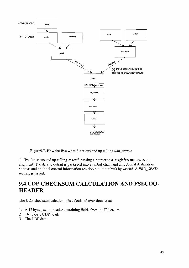
Figure9.7. How the five write functions end up calling udp_output
all five functions end up calling sosend, passing a pointer to a msghdr structure as anargument. The data to output is packaged into an mbuf chain and an optional destinationaddress and optional control information are also put into mbufs by sosend. A PRU_SENDrequest is issued.
9.4.lTDP CHECKSUM CALCULATION AND PSEUDOHEADER
The UDP checksum calculation is calculated over three area:
1. A 12 byte pseudo-header containing fields from the IP header2. The 8-byte UDP header3. The UDP data
45

o 15 16 31
32-bit source IP address
32-bit destination IP address
zero 8-bit 16-bitprotocol UDP
length
16-bit source 16-bit destinationport number port number
16_bit 16·bit UDPUDP length checksum
UDPpseudoheader
UDPheader
Figure9.8. pseudo-header used for checksum computation and UDP header
The following three facts are used in computing the UDP checksum
1. The third 32-bit word in the pseudo header looks similar to the third 32-bit word in the IPheader.
2. The order of the three 32-bit values in the pseudo-header is irrelevant. Actually, thecomputation of the Internet checksum does not depend on the order of the 16-bit valuesthat are used.
3. Including additional 32-bit words of 0 in the checksum computation has no effect.
9.5.UDP INPUT
UDP input occurs when IP input receives an IP datagram on its input queue whose protocolfield specifies UDP.IP calls the function udp_input through the prinput function in protocol switch.We'll divide udp_input function into three sections:1. The general validation that UDP performs on the received datagram2. Processing UDP datagrams destined for a unicast address: locating the appropriate PCB
and placing the datagram onto the socket's buffer3. Processing UDP datagrams destined for a broadcast or multicast address: the datagram
may be delivered to multiple sockets.
46

When udp_input receives a datagram, it first perfonns a general validation (the length andchecksum); the processing then differs depending on whether the destination IP address is aunicast address or a broadcast or multicast address.A unicast datagram is delivered to at most one process, but a broadcast or multicast datagramcan be delivered to multiple processes. A one-behind cache is maintained for unicastdatagrams, which maintains a pointer to the last Internet PCB for which a UDP datagram wasreceived.The udp_ctlinput function is called to handle received ICMP messages, and the udp_usrreqfunction handles the PRU_xxx requests from the socket layer.
47

lO.INTERFACE LAYER
IO.I.INTRODUCTION
We start at the bottom of the protocol stack with the interface layer, which includes thehardware and software that sends and receives packets on locally attached network.The interface layer supports provides for all devices:• A well-defined set of interface functions• A standard set of statistics and control flags• A device-independent method of storing protocol addresses• A standard queueing method for outgoing packetsThere is no requierement that the interface layer reliable delivery of packets, only a best-effortservice is required. Higher protocol layers must compensate for this lack of reliability.
lfnet STRUCTURE
The ifnet structure contains information common to all interfaces. During systeminitialization, a separate ifnet structure is allocated for each network device.Every ifnet structure has a list of one or more protocol addresses associated with it.
if net {}
if addr { }
if addr { }
if addr { }
Figure10.1. each ifnet structure has a list of associated ifaddr structure
The interface in figure above is shown with three protocol addresses stored in ifaddrstructures. Al though some network interfaces, such as SLIP, support only a single protocol,others, such as Ethernet, support multiple protocols and need multiple addresses.
48
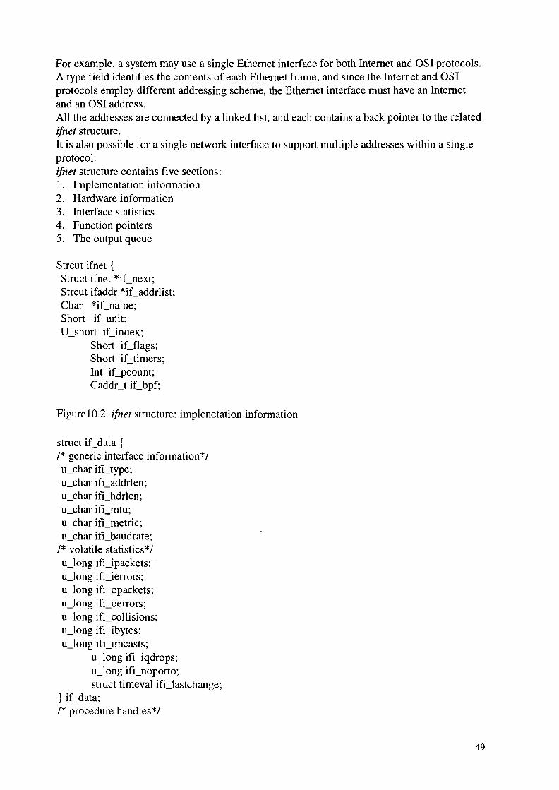
For example, a system may use a single Ethernet interface for both Internet and OSI protocols.A type field identifies the contents of each Ethernet frame, and since the Internet and OSIprotocols employ different addressing scheme, the Ethernet interface must have an Internetand an OSI address.All the addresses are connected by a linked list, and each contains a back pointer to the relatedifnet structure.It is also possible for a single network interface to support multiple addresses within a singleprotocol.ifnet structure contains five sections:1. Implementation information2. Hardware information3. Interface statistics4. Function pointers5. The output queue
Strcut ifnet {Struct ifnet *iCnext;Strcut ifaddr *iCaddrlist;Char *iCname;Short iCunit;V_short iCindex;
Short iCflags;Short iCtimers;Int iCpcount;Caddct iCbpf;
Figure10.2. ifnet structure: implenetation information
struct iCdata {/* generic interface information*/u_char ifi_type;u_char ifi_add.rlen;u_char ifLhdrlen;u_char ifi_mtu;u_char ifi_metric;u_char ifi_baudrate;
/* volatile statistics*/u_Iong ifLipackets; .u_Iong ifi_ierrors;u_Iong ifi_opackets;u_Iong ifi_oerrors;u_Iong ifLcollisions;u_Iong ifi_ibytes;u_Iong ifi_imcasts;
u_Iong ifi_iqdrops;u_Iong ifi_noporto;struct timeval ifi_Iastchange;
} iCdata;/* procedure handles*/
49

int (*iCinit)(int);
int (*iCoutput)(struct ifnet *, struct mbuf *, struct sockaddr *,struct rtentry *);
int (*iCstart)(struct ifnet *);
int (*iCdone)(struct ifnet *);
int (*iCioctl)(struct ifnet *, int, caddr_t);
int (iCreset)(int);
int (*iCwatchdog)(int);
struct ifqueue {struct mbuf *ifq_head;struct mbuf *ifq_tail;int ifq_len;int ifq_maxlen;
int ifq_drops;} iCsnd;
} ;#define iCmtu#define iCtype#define iCaddrlen#define iChdrlen#define iCmetric#define iCbaudrate
iCdata.ifLmtuiCdata.ifLtypeiCdata.ifi_addrleniCdata.ifi_hdrleniCdata.ifi_metriciCdata.ifLbaudrate
Figure 10.3. ifnet structure: interface charactristics, statistics, procedures and output queue
50

ifnet {}
_ _ _ _ _ _ • more interface
ifaddr{ }
ifaddr{ }
Figure lOA. ifnet and ifaddr structure
lO.2.Ifaddr STRUCTlTRE
Each interface maintains a linked list of ifaddr structures because some data links, such asEthernet, support more than one protocol. A separate ifaddr structure describes each addressassigned to the -interface, usually one address per protocol.Another reason to support multiple addresses is that many protocols, including TCPIIPsupport multiple addresses assigned to a single physical interface.Struct ifaddr {Struct ifaddr *ifa_next;Struct ifnet *ifa_ifp; Struct sockaddr *ifa_addr;
Struct sockaddr *ifa_dstaddr;#define ifa_broadaddr ifa_dstaddrstruct sockaddr *ifa_netmask;void (*ifa_rtrequest) ( );u_short ifa_flags;short ifa_refcnt;int ifa_metric;
} ;
Figure 10.5. ifaddr structure
51

lO.3.Sockaddr STRUCTURE
Addressing infonnation for an interface consists of more than a single host address. By using ageneric structure like sockaddr, hardware and protocol specific addressing details are hiddenfrom the interface layer.
datasockaddr{} ELfamilY
len
L-- _
14 bytes
dataosockaddr {} I lam;.
----'--------------
214 bytes
Figure 10.6. sockaddrand osockaddr structures
lO.4.ifnet and ifaddr specialization
The ifnet and ifaddr structures contain general infonnation applicable to all network interfaceand protocol addresses.To accommodate additional device and protocol-specific infonnation, each driver definesandeach protocol allocates a specialized version of the ifnet and ifaddr structures. Thesespecialized structures always contain an ifnet or ifaddr structure as their first member so thatthe common infonnation an ifnet or ifaddr structure as their first member so that the commoninfonnation can be accessed without consideration for the additional specialized information.
Ethernet
SLIP
loif:
loopback
Figure 10.7. arrangement of ifnet structures within device_dependent structures
52

Each protocol stores addressing infonnation for each interface in a list of specialized ifaddrstructures. The Internet protocols use an in_ifaddr structure and the OSI protocols aniso_ifaddr structure.In addition to protocol addresses, the kernel assigns each interface a link-level address whenthe interface is initialized, which identifies the interface within the kernel.The kernel constructs the link-level address by allocating memory for an ifaddr structure andtwo sockaddr_dl structures-one for the link-level address itself and one for the link-leveladdress mask. The sockaddr_dl structures are accessed by OSI, ARP, and the routingalgorithms.
lO.5.Network initialization
ifnet ( )
ifaddr ( )
Link-Level address
Ethernet address
OSI address
sockaddr_dl ( )
sockaddr_dl ()
ifaddr ( )
ifaddr ( )
Figure 10.8. An interface address list containing Link-level, Ethernet, and OSI addresses
lO.6.Ethernet initialization
As part of cpu_startup, the kernel locates any attached network devices. Once a device isidentified, a device specific initialization function is called.Each device driver for a network interface initialize a specialized ifnet structure and callsif_attach to insert the structure into the linked list of interfaces.The le_softc structure is the specialized ifnet structure for our Ethernet driver.
Struct le_softc {Struct arpcom sc_ac;
#define sc_if sc_ac.ac_if#define sc_addr sc_ac.ac_enaddr
53

/* device- specific members*/} le_softc [NLE];
Figure 10.9. Ie_sofie structure
lO.6.l.Ethernet interface
Ethernet frames consist of 48-bit destination and source addresses followed by a 16-bit fieldthat identifies the format of the data carried by the frame. For IP packets, the type is Ox0800(2048). The frame is terminated with a 32-bit CRC, which detects errors in the frame.
destination source type data eReaddress address
6 BYTES 6 BYTES 2 46-1500 BYTES : 4 BYTES
ItypeIP packeteaoo
2 46-1500 BYTES
Figure 10.9.Ethernet encapsulation of an IP packet
p
OSI ipintr ARP~
-yiCoutput
protocols protocol ... ether_outputIII"""
+ ..4l ...I clnlintrq arpintrq
L le_softc[O].. "l
ipintrq: ifnet{ }
~,r
• iCsndarpcom {}
ether_input
le_softc {}...lestartlerad
~~J~
tleint
outputinput packets
tinterru ts" packets
Figure 10.11. Ethernet device driver
We will prefer to the 48-bit Ethernet addresses as hardware addresses. The translation from IPto hardware address is done by the ARP protocol (RFC 826) and from hardware to IPaddresses by the RARP protocol (RFC 903).
54

We start with the reception of Ethernet frames. We assume that the hardware has beeninitialized and the system has been configured so that leintr is called when the interfacegenerates an interrupt.Leintr examines the hardware and, if a frame has arrived, calls lread transfer the frame fromthe interface to a chain of mbufs (with m_devget). If the hardware reports that a frametransmission has completed or an error has been detected (such as a bad checksum), leintrupdates the appropriate interface statistics, resets the ahrdware, and calls lestart, whichattempts to transmit another frame.All Ethernet device drivers deliver their received frame to ether_input for further processing.The mbuf chain constructed by the device driver does not include the Ethernet header, so it ispassed as a separate argument to Ether_input.The Ethernet CRC is not generally available. It is computed and checked by the interfacehardware, which discards frames that arrive with an invalid CRe.
55

11.TCP: TRANSMISSION CONTROLPROTOCOL
11.I.INTRODUCTION
The tranmission control protocol, or TCP, provides a connection-oriented, reliable, bytestream service between the two end points of an application. This is completely different fromUDP's connectionless, unreliable, datagram service.
"
,r
tp-U99:1
IRL
"tp-aJpl
"ip_aJpl
b1):ljrpl
tpjil
min
"
"
6ay ID11; 6ay IDlI_al
dntlJs
"EJ lP_~ lP_ct.i1
Figure 11.1. Relationship of TCP functions to rest of the kernel
56

12.2.TCP HEADER
16-bit source 16-bit destinationport number port number
32-bit sequence number
32-bit acknowledgment number
4·bit R fheade Ileng1h
reserved ~ ~N
r.- 16-bit window
16-bit TCP checksum 16-bit urgent offset
1'--- options (if any) "l"-
I'-- data (ff any) -::1'
Figure 11.2. TCP header fields
1l.2.l.TCP HEADER FORMAT
SOURCE PORT: This filed identifies the upper-layer application using the TCP connection.
DESTINATION PORT: This field identifies the upper-layer application using the TCPconnection.
SEQUENCE NUMBER: The value in this field identifies the transmitting byte stream. This isused during connection-management operations.
ACKNOWLEDGEMENT NUMBER: The value in this field reflects a value acknowledgingdata previously received.
DATA OFFSET: This value determines where the field of data begins.
RESERVED: This field is reserved, and the bits within it are set to zero.
URGENT: This field indicates if the urgent pointer is used.
ACKNOWLEDGEMENT: This indicates whether or not the acknowledgement field issignificant.
57

PSH: This field indicates if the PUSH function is used.
RESET: The value in this field indicates whether the connection should be reset.
SYNCHRONIZE: This is used to indicate the sequence numbers are to be synchronized.
FINISHED: This field is used to indicate that the sender has no more data to send.
WINDOW: this value indicates how much data the receiving host can accept. The value inthis field is contingent on the value in the acknowledgement field.
CHECKSUM: This performs a checksum on the 16-bit words in the segment.
URGENT POINTER: This field, if used, indicates that urgent data follows.
OPTIONS: At the current time, three basic options are implemented in this field: end-of-list,no options, and maximum segment size.
PADDING: This field is used to ensure the header length 32 bits.
DATA: user data follows in this field.
The TCP header is defined as a tcphdr structure.
Struct tcphdr {U_short th_sport;
U_short th_dport;Tcp_seq th_seq;Tcp_seq th_ack;#if BYTE_ORDER == LITTLE_ENDIAN
u_char th_x2:4,th_off:4;
#endif#if BYTE ORDER == BIG ENDIAN
u_char th_off:4,th_x2:4;
#endifu_char th_flags;u_short th_win;u_short th_sum;u_short th_urp;
} ;
Figure 11.3. TCP header structure
The 4-bit header length, the 6 reserved bits that follow, and the 6 flag bits are defined in C astwo 4-bit fields, followed by 8 bits of flags. to handle the difference in the order of these 4bits fields within an 8-bit byte, the code contains an #ifdefbased on the byte order of thesystem.
58

The thJlags member contains 6 flags bits, accessed using the names shown in this figure:
thJla/?s DESCRIPTIONTH ACK The acknowledgment number (th ack) is validTH FIN The sender is finished sending dataTH PUSH Receiver should pass the data to application without delayTH RST Reset connectionTH-SYN Synchronize sequence numbers (establish connection)TH URG The urgent offset (th urp) is valid
Figure 11.4. thJlags values
Struct tcpiphdr {Struct ipovly ti_I;
Struct tcphdr ti_I;};#define ti_next tLi.ih_next#define ti_prev tLi.ih_prev#define ti_xl ti_i.ih xl#define ti_pr ti_i.ih_pr#define ti_Ien ti_i.ih_Ien#define tLsrc ti_i.ih_src#define ti_dst ti_i.ih_dst#define ti_sport ti_tth_sport#define tLdport ti_tth_dport#define tLseq tLtth_seq#define tLack ti_tth_ack#define ti_x2 ti_tth_x2#define tLoff ti_tth_off#define ti_flags ti_t.th_flags#define ti_win ti_t.th_win#define tLsum ti_tth_sum#define tLurp ti_tth_urp
Figure 11.5. tcpiphdr structure: combined IPrrCp header
The 20-byte IP header is defined as an ipovly structure, which we showed earlier in figure(UDP section I'll get back to that).
59

11.3.TCP CONTROL BLOCK
TCP maintains its own control block, a tcpcb structure, in addition to the standard internetPCB.The TCP control block is a large structure, occupying 140 bytes. As shown in the figure ****there is an one-to one relationship between the Internet PCB and the TCP control block, andeach point to the other.
00'
~..,•• _ _ _ _ _ _ _ _ _ _ _ _ _ Iayoar
,npctI{) protocol....~~~~~~
l~':'!)
doubly linked circular list of all TCP~ - - - - - - - - - - - - - - - - - - - - - - - - - - - - - - - --..
Internet protocol control blocksand associated rep control blocks
Figure 11.6. Internet protocol control blocks ad their relationship to other structure
60
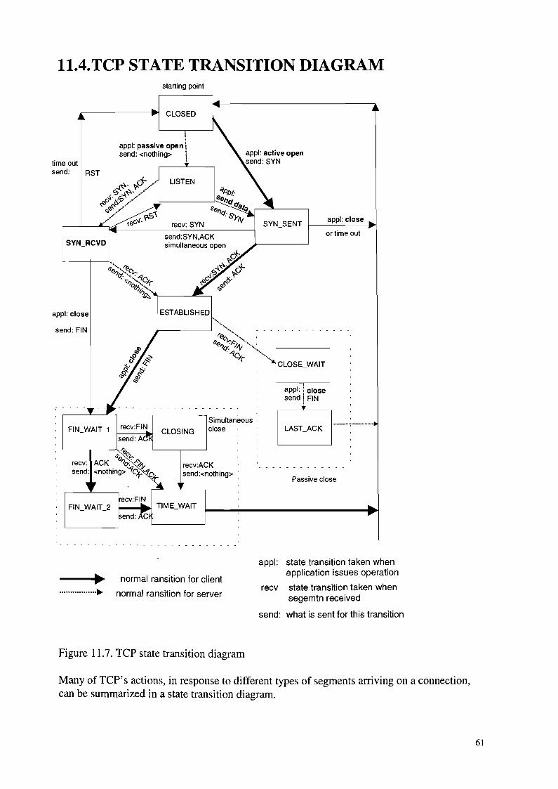
11.4.TCP STATE TRANSITION DIAGRAMstarting point
CLOSED
appl: close
or time out
appl: passive open \send: <nothing> i,
time outsend: RST
Passive close
appl: ~ closesend! FIN
I~T'ACK H----Simultaneous 'close
recv:ACKsend:<nothing> :
CLOSING
ESTABLISHED
recv:FIN
send: AL------.---"'"'-r(9.
.s'(9. "t-.recv: ACK "C?: ~4'send: <nothing> ~C'1-('1.
send: FIN
appl: close
-.......,~.................~
normal ransition for client
normal ransition for server
appl: state transition taken whenapplication issues operation
recv state transition taken whensegemtn received
send: what is sent for this transition
Figure 11.7. TCP state transition diagram
Many of TCP's actions, in response to different types of segments arriving on a connection,can be summarized in a state transition diagram.
61

These state transitions define the TCP finite state machine. Although the transition fromLISTEN to SYN_SENT is allowed by TCP, there is no way to do this using the socket API(i.e., a connect is not allowed after a listen).The estate member of the control block holds the current state of a connection, which thevalue is shown in figure 12.7.. This figure also shows the tep_outflag contains the outgoingflags for tep_output to use when the connection is in the state.
estate value Description TCP outflags[]TCPS_CLOSED 0 Closed TH_RST /
TH ACKTCPS LISTEN 1 Listening for connection (passive open) 0
TCPS SYN SENT 2 Have sent Syn (active open) TH_SYN
TCPS_SYN_RECE 3 Have sent and received SYN; awaiting TH_SYN /TH_ACK
NED ACK
TCPS_ESTABLIS 4 Established (data transfer) TH_ACK
HEDTCPS_CLOSE_W 5 Received FIN, waiting for application TH_ACK
AIT close
TCPS_FIN_WAIT 6 Have closed, sent FYN; awaiting ACK TH_FIN /TH_ACK
1 and FIN
TCPS CLOSING 7 Simultaneous close; awaiting ACK TH FIN / TH ACKTCPS_LASLACK 8 Rewceived FIN have closed; awaiting TH_FIN / TH_A CK
ACKTCPS FIN WAIT 2 9 Have closed;awaiting FIN TH ACKTCPS TIME WAIT 10 2msl wait after active close TH ACK
Figure 11.8. estate value
Figure 12.8. also shows the numerical values of these contants since the code uses theirnumerical relationships.Similarly, tep_notify handles ICMP errors differently when the connection is not yetestablished, that is, when estate is less than TCPS_ESTABLISHED.
114.l.HALF CLOSE
When a process calls shutdown with a second argument of 1, it is called a half_close. TCPsends a FIN but allows the process to continue receiving on the socket.
62

11.5.TCP INITIALIZATION
The domaininit function calls TCP's initialization function, tep_init at system initializationtime.
VoidTcp_init (){
tcp_iss =I;tcb.inp_next =tcp.inp_prev =&tcb;if (max_protohdr , sizeof(struct tcpiphdr))
max_protohdr =sizeof(struct tcpiphdr);if (max_Iinkhdr + sizeof(struct tcpiphdr) . MHLEN)
panic("tcp_init");
Figure 11.9.tep_init function
11.6.SET INITIAL SEND SEQUENCE NUMBER (ISS)
The initial send sequence number (ISS), tep_iss is nitialized to I. As the comment indicates,this is wrong.we discuss the implications behind this choice when we describe TCP's quiettime.
1l.6.l.INITIALIZE LINKED LIST OF TCP INTERNET PCBS
The next and previous pointers in the head PCB (teb) point to itself. This is an empty doublylinked list. The remainder of the teb PCB is nitialized to O.
1l.6.2.CALCULATE MAXIMUM PROTOCL HEADER LENGTH
If maximum protocol header encountered so far is less than 40 bytes, max-protohdr is set to40 (the size of the combined IP and TCP headers, without any options). If the sum ofmax-protohdr (normally 16) and 40 is greater than the amount of data that fits into mbuf witha packet header (l00 bytes, MHLEN), the kernel panics.
1l.6.3.MSL AND QUIET TIME CONCEPT
TCP requires any host that crashes without retaining any knowledge of that last sequencenumber used on active connections to refrain from sending an TCP segments for one MSL ( 2minutes, the quiet time) on reboot.MSL is the maximum segment lifetime. Each implementation chooses a value for the MSL. Itis the maximum amount of time any segment can exit in the network before being discarded.A coonection that is actively closed remains in the CLOSE_WAIT state for twice the MSL.The problem occurs if packets are delayed somewhere in the network.The following script is one example of how an old segment can incorrectly be delivered to aconnection:1. A client and server have an established connection. The client's port number is 1024. The
client. The client sends a data segment with a starting number of 2. The data segment gets
63

trapped in a routing loop somewhere between the two end points and is not delivered tothe server. This data segment becomes a wandering duplicate.
2. The client retransmits the data segment starting with sequence number 2, which isdelivered to the server.
3. The client closes the connection.4. The client host crashes.5. The client host reboots about 40 seconds after crashing, causing TCP to initialize tcp_iss
to I again.6. Another connection is immediately established by the same client to the same server, using
the same socket pair: the client uses 1024 again, and the server uses its well-known port.The client's SYN uses sequence number 1. This new connection using the same socketpair is called a new incarnation of the old connection.
7. The wandering duplicate from step I is delivered to the server, and it thinks this datagrambelongs to the new connection, when it is really from the old connection.
Besides saving the sequence number of all established connections, the only other way aroundthis problem is for the rebooting TCP to be quiet for MSL seconds after crashing.
12.TCP TIMERS
12.1.INTRODUCTION
TCP maintains seven timers for each connection. They are briefly described here, in theapproximate order of their occurrence during the lifetime of a connection.
I. A connection-establishment timer starts when a SYN is sent to establish a new connection.If a response is not received within 75 seconds, the connection establishment is aborted.
2. A retransmission timer is set when TCP sends data. If the data is not acknowledged by theother end when this timer expires, TCP retransmits the data. The value of this timer (i.e.,the amount of timer TCP waits for an acknowledgment) is calculated dynamically, basedon the round-trip time measured by TCP for this connection, and based on the number oftimes this data segment has been retransmitted. The retransmission timer is bounded byTCP to be between I and 64 seconds.
3. A delayed ACK timer is set when TCP receives data that must be acknowledged, but neednot be acknowledged immediately. Instead, TCP has data to send on this connection, thepending acknowledgment is sent along with the data (called piggybacking).
4. A persist is set when the other end of a connection advertises a window of 0, stopping TCPfrom sending data. Since window advertisements from the other end are not sent reliably(that is, ACKs are not acknowledged, only data is acknowledged), there's a chance that afuture window update, allowing TCP to send some data, can be lost. Therefore, if TCP hasdata to send and the other end advertises a window of 0, the persist timer is set and when itexpires, I byte of data is sent to see if the window has opened. Like the retransmissiontimer, the persist timer values is calculated dynamically, based on the round-trip time. Thevalue of this is bounded by TCP to be between 5 and 60 seconds.
5. A keepalive timer can be set by the process using the SO_KEEPALIVE socket option. Ifthe connection is idle for 2 hours, the keepalive timer expiresand a special segment is sentto the other end, forcing it to respond. If the expected response is received, TCP knows thatthe other host is still up, and TCP won't probe it again until the connection is idle for
64

another 2 hours. Other responses to the keepalive probe tell TCP that the other host hascrashed and rebooted. If no response is received to a fixed number of keepalive probes,TCP assumes that the other end has crashed, although it can't distinguish between the otherend being down (i.e., it crashed and has not yet rebooted) and a temporary lack ofconnectivity to the other end (i.e., an intermediate router or phone line is down).
6. AFIN_WAIT_2 timer. When a connection moves from the FIN_WAIT_I state to theFIN_WAIT_2 state and the connection cannot receive any more data (implying the processcalled close, instead of taking advantage of TCP's half-close with shutdown), this timer isset to 10 minutes. When this timer expires it is reset to 75 seconds, and when it expires thesecond time the connection is dropped. The purpose of this timer is to avoid leaving aconnection in the FIN_WAIT_2state forever, if the other end never sends a FIN.
7. A TIME_WAIT timer often called the 2MSL timer. The term 2MSL means twice the MSL,the maximum segment lifetime. It is set when a connection enters the TIME_WAIT State,that is, when the connection is actively closed. When the connection enters theTIME_WAIT State and when it expires, the TCP control block and Internet PCB aredeleted, allowing that socket pair to be reused.
TCP has two timer functions: one is called every 200 ms (the fast timer) and the other every500 ms (the slow timer). The delayed ACK timer is different from the other six: when thedelayed ACK timer is set for a connection it means that a delayed ACK must be sent the nexttime the 200-ms timer expires (Le., the elapsed time is between 0 and 200 ms). The other sixtimers are decremented every 500 ms, and only when the counter reaches 0 does thecorresponding action take place.
12.2.tcpJasttimo FUNCTION
The function tcpJatstimo, is called by prJasttimo every 200 ms. it handles only the delayedACK timer.voidtcp_fasttimo ( ){
struct inpcb *inp;struct kpcb *tp;int s = spInet ( );inp = tcb.inp_next;if (inp)for (; inp != &tcb; inp = inp ->inp_next)
if ((tp =(struct tcpcb *) inp->inp_ppcb) &&(tp->Cflags & TF_DELACK)) {tp->T_flags &= -TF_DELACK;tp->cflags I=TF_ACKNOW;tcpstat.tcps_delack++;(void) tcp_output (tp);}
splx (s);
figure 12.1. tcpJasttimo function, which is called every 200 ms
65

Each Internet PCB on the TCP list that has a corresponding TCP control block is checked. Ifthe TF_DELACK flag is set, it is cleared and the TF_ACKNO flag is set, an ACK is sent.When a socket is created (the PRU_ATTACH request, in response to the socket system call),the creation of the Internet PCB is done first, followed by the creation of the TCP controlblock. Between these two operations a high-priority clock interrupt can occur, which callstepJasttimo.
12.3.tcp_slowtimo FUNCTON
the function tep_slowtimo, is called by pr_slowtimo every 500 ms. It handles the other sixTCP timers: connection establishment, retransmission, persist, keepalive, FlN_WAIT_2, and2MSL.
12.3.l.tcp_timers FUNCTION
The function tep_timers is called by TCP's PRU_SLOWTIMO request.:
case PRU_SLOWTIMO:tp =tcp_timers (tp, (int)nam) ;
when anyone of the four TCP timer counters reaches O.
12.3.2.FIN_WAIT_2 and2MSLTIMERS
TCP's TCPT_2MSL counter implements two of TCP's timers.1. FlN_WAIT_2 timer. When tep_input moves from the FlN_WAIT_1 state to the
FIN_STATE_2 state and the socket cannot receive any more data (implying the processcalled close, instead of taking advantage of TCP' s half-close with shutdown), theFlN_WAIT_2 timer is set to 10 minutes (tep_maxidle). We'll see that this prevents theconnection from staying in the FlN_WAIT_2 state forever.
2. 2MSL timer. When TCP enters the TIME_WAIT state, the 2MSL timer is set to 60 seconds(TCPTV_MSL times 2).
v119
119 clock ticks x500 msltick .=59.5 seconds
~-------~~o
v-somewhere in hereconnection entersTIME_WAIT stale, 2MSLtimer set for 60 seconds(120 ticks) in the future
SOOmsper tick
prlowtimo I)callstep_slowlimo ()callslcp_usrreqIPRU_SLOWTIMO)callstq:J_timers(TCPT_2MSL)callsTCP_CLOSE I)
Figure 12.2. Setting and expiration of 2MSL timer in TIME_WAIT state
66

~1200 ticks ~"""'75 seconds)1lI""""
r---(1-0m-inu-tes-)--~i "..-, rt + +
enter FIN_WAIT_2 state;FIN_WAIT_2 timer set to1200 (tcp_maxidle);Udle=O
FIN_WAIT_2timer expires;Udle=1198;FIN_WAlT_2 timerset to 150(tcp_keep;ntv~
FIN_WAlT_2timer expires;t idle = 1198+150;tqUlose ()
Figure 12.3. FIN_WAIT_2 timer to avoid infinite wait in FIN_WAIT 2 state
the connection moves from the FIN_WAIT_1 state to the FIN_WAIT_2 state on the receipt ofan ACK. Receiving this ACK sets Cidle to 0 and the FIN_WAIT_2 timer is set to 1200(tep_maxidle).The reason for the 75-second timeout after the first lO-minute timeout is as following:a connection in the FIN_WAIT_2 state is not dropped until the connection has been idle formore than 10 minutes. There's no reason to test cidle until at least 10 minutes have expired,but once this time has passed, the value of cidle is checked every 75 seconds. Since aduplicate segment could be received, say a duplicate of the ACK that moved the connectionfrom the FIN_WAIT_1 state to the FIN_WAIT_2 state, the 10-minute wait is restarted whenthe segment is received (since Cidle will be set to 0).
12.4.PERSIST TIMER
/** Persistence timer into sero window.* force a byte to be output, if possible.*/
case TCPT_PRES1ST:tcpstat.t~ps_presisttimeo++;
tcp_setpresist (tp);tp->cforce =1;(void) tcp_output (tp);tp->Cforce =0;break;
Figure 12.4. tep_timers function: expiration of persist timer
12.4.l.FORCE WINDOW PROBE SEGMENT
when the persist timer expires, there is data to send on the connection but TCP has beenstopped by the other end's advertisement of a zero-sized window. Tep_setpersist calculatesthe next value for the persist timer and stores it in the TCPT_PRESIST counter. The flagtJoree is set to 1, forcing tep_output to send 1 byte, even though the window advertised bythe other end is O.
67

220
ftIT-i_24_+-_48 6_0_-+1_6_0_se_co_nd_S~~
o 5 10 16 28 52 100 160
Figure 12.5. Time line of presist timer when probing a zero window
Once the value of the persist timer reaches 60 seconds, TCP continues sending window probesevery 60 seconds. The reason the first two values are both 5, and not 1.5 and 3, is that thepresist timer is lower bounded at 5 seconds. It is also upper bounded at 60 seconds. Themultiplication of each value by 2 to give the next value is called an exponential backoff.
12.5.COONECTION ESTABLISHMENT ANDKEEPALIVE TIMERS
TCP's TCPT_KEEP counter implements two timers:
1. when a SYN is sent, the connection-establishment timer is set to 75 seconds(TCPTV_KEEPjN11). This happens when connect is called, putting a connection into theSYN_SENT state (active open), or when a cnnection moves from the LISTEN to theSYN_RCVD state (passive open). If the connection doesn't enter the ESTABLISHED statewithin 75 seconds, the connection is dropped.
2. when a segment is received on a connection, tcp_input resets the keepalive timer for thatconnection to 2 hours (tcp_keepalive), and the Cidle counterfor the connection is reset to O.This happens for every TCP connection on the system, whether the keepalive option isenabled for the socket or not. If the keepalive timer expires (2 hours after the last segmentwas received on the connection), and if the socket option is set, the keepalive timer is justreset for 2 hours in the future.(tcp_timers function)
connection
establishment ~timer: ----------------o
. 24 4B socmdsretransmiSSi0L...:..j Itimer: I Ir--------------
~ ~ ~ ltransmit retransmitSYN SYN
retransmitSYN
Figure 12.6. Connection-establishment timer and retransmission timer after SYN is sent
12.6.RETRANSMISSION TIMER CALCULATIONS
The timers that we've described so far in this chapter have fixed times associated with them:200 ms for the delayed ACK timer, 75 seconds for the connection-establishment timer, 2hours for the keepalive imter, and so on.
68

Fundemental to the operation of TCP is setting a retransmission timer when a segment istransmitted and an ACK is required from the other end. If the ACK is not received an ACKfor data segments but does not require an ACK for a segment without data (i.e., a pure ACKsegment). If the calculated retransmission timeout is too small, it can expire prematurely,causing needless retransmission. If the calculated value is too large, after a segment is lost,additional time is lost before the segment is retrams,itted, degrading performance.Complicating this is that the round-trip times between two hosts can vary widely anddynamically over the course of a connection.TCP calculates the retransmisson timeout (RTO)by measuring the round-trip time( nticks) of data segments and keeping track of the smoothedRTT estimator (srtt) and a smoothed mean deviation estimator (rttvar). The mean deviation isa good approximation of the standard deviation, but easier to compute since, unlike thestandard deviation, the mean deviation does not require square root calculations.[Jacobson 1988b] provides additional details on these RTT measurements, which lead to thefollowing equations:
delta =nticks-srttsrt ~ srtH g x deltarttvar ~ rttvar + h( Ideltal - rttvar)RTO = srtt + 4 x rttvar
delta is the difference between the measured round trip just obtained (nticks) and the currentsmoothed RTT estimator (srtt). g is the given applied to the RTT estimator and equals 1/8. His the gain applied to the mean deviation estimator and equals 1.40 The two gains and themultiplier 4 in the RTO calculation are purposely powers of 2, so they can be calculated usingshift operation instead od multiplying of dividing.
12.7.tcp_newtcpcb FUNCTION
A new TCP control block is allocated and initialized by tcp_newtcpcb. This function is calledby TCP's PTU_AITACH requesr when a socket is created. The caller has previously allocatedan Internet PCB for this connection, pointed to by the arguement inp.
12.8.tcp_setpresist FlTNCTION
The next function we look at that uses TCP's retransmission timeout calculations istcp_setpresist. This timer is set when TCP has data to send on a connection, but the other endis advertising a window O. This function calculates and stores the next value for the timer.
12.9.tcp_xmit_timer FUNCTION
The next function we look at, tcp_xmiCtimer, is called each time an RTT measurement iscollected, to update the smoothed RTT estimator (srtt) and the smoothed mean deviationestimator (rttvar).The arguement rtt is the RTT measurement to be applied. It is the value nticks + 1. It can befrom one of two sources:
69

1. If the timestamp option is present in a received segment, the measured RTT is the currenttime (tcp_now) minus the timestamp value.
2. If timestamp are not in use and a data segment in being timed.
12.10.SUMMARY
the two functions tcpJasttimo and tcp_slowtimo are called by the kernel every 200 ms andevery 500 ms, respectively. These two functions drive TCp's pre-connection timermaintaince.
TCP maintains the following seven timers for each connection:• a connection-establishment timer,• a retransmission timer,• a delayed ACK timer,• a presist timer,• a keepalive timer,• a fin_waiC2 timer, and• a 2MSL timer.The delayed ACK timer is different from the other six, since when it is set it means a delayedACK must be sent the next time TCP's 200-ms timer expires. The other six timers arecounters that are decremented by 1 every time TCP's 500-ms timer expires.When anyone of the counters reaches 0, the appropriate action is taken: drop the connection,retransmit a segment, send a keepalive probe, and so on.Since some of the timers are mutually execlusive, the six timers are really implemented usingfour counters, which complicates the code.TCP maintains two smoothed estimators for a connection: the round-trip time and the meandeviation of the RTT. Although the algorithms are simple and elegant, these estimators aremaintained as scaled fixed-ppoint numbers ( to provide adequate precision without usingfloating-point code within the kernel), which complicates the code.
13.TCP' OUTPUT
13.1.INTRODUCTION
The function tcp_output is called whenever a segment needs to be sent on a connection. Thereare numerous calls to this function from other TCP functions:
• tcp_ursreq calls it for various requests: PRU_CONNECTto send the initial SYN,PRU_SHUTDOWN to send a FIN, PRU_RCVD in cas a window update can be sent afterthe process has read some data from the socket receive buffer, PRU_SEND to send data.
• tcpJasttimo calls it to send a delayed ACK.• tcp_timers calls it to retransmit a segemnt when the retransmission timer expires.• tcp_timers calls it to send a persist probe when the presist timer expires.• tcp_drop calls it to send an RST.• tcp_disconnect calls it to send a FIN.• tcp_input calls it when output is required or when an immediate,ACK should be sent.
70

• tcp_input calls it when a pure ACK is processed by the header prediction code and there ismore data yo send. (A pure ACK is a segment without data that just acknowledges data.)
• tcp_input calls it when the third consecutive duplicate ACK is received, to send a singlesegment (the fast retansmit algorithm).
Tcp_output first determines whether a segment should be sent or not. TCP output is controlledby numerous factors other than data being ready to send to the other end of the connection. Forexample, the other end might be advertising a window of size 0 that stops TCP from sendinganything, the Nagle algorithm prevents TCP from sending lots of small segments, and slowstart and congestion avoidance limit the amount of data TCP can send on a connection.Conversely, some functions set flags just to force tcp_output to send a segment, such as theTF_ACKNOW flag that means an ACK should be sent immediately and not delayed. Iftcp_output decides not to send a segment, the data (if any) is left in the socket's send bufferfor a later call to this function.
13.2.DETERMINE IF A SEGMENT SHOULD BE SENT
Sometimes tcp_output is called but a segment is not generated. For example, the PRU_RCVDrequest is generated when the socket layer removes data from the socket's receive buffer,passing the data to a process. It is possible that the process removed enough data that TCPshould send a segment to the other end with a new window advertisement, but this is just apossibility, not a certainty. The first half of tcp_output determines if there is a reason to send asegment to the other end. If not, the function returns without sending a segment.
len is the minimum of the number of bytes in the send buffer and win is the minimum of thereceiver's advertised window and the congestion window, perhaps 1 byte if output is beingforced. offis subtracted because that many bytes at the beginning of the send buffer havealready been sent and are awaiting acknowledgment.
13.3.TCP OPTIONS
The TCP header can contain options. We digress to discuss these options since the next pieceof tcp_output decides which options to send and constructs the options in the outgoingsegment.
71
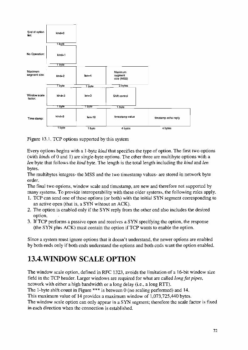
End oloption c:Jind=Olist
e
No Operation:
Maximumsegment size:
Window scalefaC1or:
Times1amp:
kind=1
DYie
Maximumkind=2 len=4 segment
size (MSS)
"! e 1 byte ""! es
kind=3 len=3 Shift control
"! e "Yle 1 byte
kind=B len=10 timestamp value timstamp echo reply
1 byte 1 byte 4 bytes 4 bytes
Figure 13.1. TCP options supported by this system
Every options begins with a I-byte kind that specifies the type of option. The first two options(with kinds of 0 and 1) are single-byte options. The other three are multibyte options with alen byte that follows the kind byte. The length is the total length including the kind and lenbytes.The multibytes integres- the MSS and the two timestamp values- are stored in network byteorder.The final two options, window scale and timestamp, are new and therefore not supported bymany systems. To provide interoperability with these older systems, the following rules apply.1. TCP can send one of these options (or both) with the initial SYN segment corresponding to
an active open (that is, a SYN wihtout an ACK).2. The option is enabled only if the SYN reply from the other end also includes the desired
option.3. IfTCP performs a passive open and receives a SYN specifying the option, the response
(the SYN plus ACK) must contain the option if TCP wants to enable the option.
Since a system must ignore options that it doesn't understand, the newer options are enabledby both ends only if both ends understand the options and both ends want the option enabled.
13.4.WINDOW SCALE OPTION
The window scale option, defined in RFC 1323, avoids the limitation of a 16-bit window sizefield in the TCP header. Larger windows are required for what are called long fat pipes,network with either a high bandwidth or a long delay (i.e., a long RTT).The I-byte shift count in Figure *** is between 0 (no scaling performed) and 14.This maximum value of 14 provides a maximum window of 1,073,725,440 bytes.The window scale option can only appear in a SYN segment; therefore the scale factor is fixedin each direction when the connection is established.
72
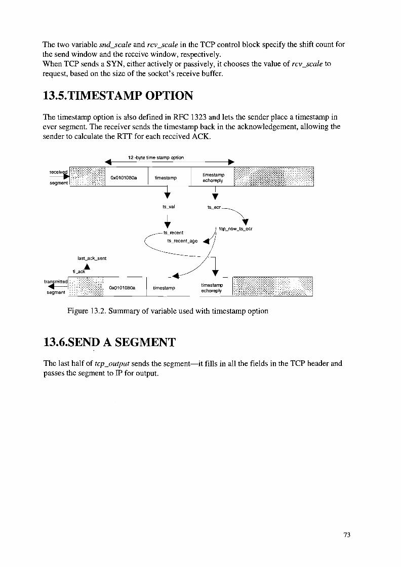
The two variable snd_seale and rev_scale in the TCP control block specify the shift count forthe send window and the receive window, respectively.When TCP sends a SYN, either actively or passively, it chooses the value of rev_scale torequest, based on the size of the socket's receive buffer.
13.5.TIMESTAMP OPTION
The timestamp option is also defined in RFC 1323 and lets the sender place a timestamp inever segment. The receiver sends the timestamp back in the acknowledgement, allowing thesender to calculate the RTT for each received ACK.
12 -byte time stamp option
Ox0101080a
ts_recent
ts_recen'-age
timestamp
Ox0101080a
Figure 13.2. Summary of variable used with timestamp option
13.6.SEND A SEGMENT
The last half of tep_output sends the segment-it fills in all the fields in the TCP header andpasses the segment to IP for output.
73

14.TCP INPUT
14.1.INTRODUCTION
TCP input processing is the largest piece of code that we examine in this text. The processingof incoming segemtns is complicated, just long and detailed.The tep_input function is called by ipintr (through the pr_input function in the protocol switchtable) when a datagram is received with a protocol field of TCP. tep_input executes at thesoftware interrupt level.The first few steps are typical: validate the input segment (checksum, length, etc.) and locatethe PCB for this connection. Given the length of the remainder of the function, however, anattempt is made to bypass all this logic with an algorithm called header prediction. Thisalgorithm is based on the assumption that segments are not typically lost or reordered, hencefor a given connection TCP can often guess what the next received segment will be. If theheader prediction algorithm works, notice that the function returns. This is the fast paththrough tep_input.The slow path through the function ends up at the label dodata, which tests a few flags andcalls tep_output if a segment should be sent in response to the received segment.
voidtcp_input ( ){
checksum TCP header and data;findpcb:
locate PCB for segment;if (not found)
goto dropwithreset;reset idle time to 0 and keepalive timer to 2 hours;process options if not LISTEN state;if (packet matched by header prediction) {
~ompletely process received segment;return;
}switch (tp->cstate) {case TCP_LISTEN:
if SYN flag set, accept new connection request;goto tdmthenstep6;
case TCP_SYN_SENT:if ACK of our SYN, connection completed;
trimthenstep6:trim any data not within window;goto step6;
process RFC 1323 timestamp;check if some data bytes are within the receive window;trim data segment to fit within window;if (RST flag set) {
74
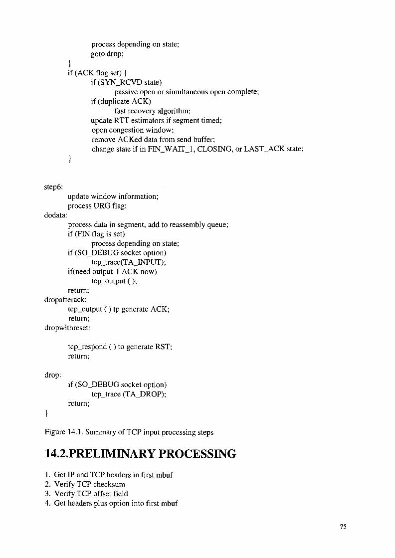
process depending on state;goto drop;
}if (ACK flag set) {
if (SYN_RCVD state)passive open or simultaneous open complete;
if (duplicate ACK)fast recovery algorithm;
update RTT estimators if segment timed;open congestion window;remove ACKed data from send buffer;change state if in FIN_WAIT_1, CLOSING, or LAST_ACK state;
step6:update window information;process URG flag;
dodata:process data in segment, add to reassembly queue;if (FIN flag is set)
process depending on state;if (SO_DEBUG socket option)
tcp_trace(TA_INPUT);if(need output II ACK now)
tcp_output ( );return;
dropafterack:tcp_output () tp generate ACK;return;
dropwithreset:
tcp_respond ( ) to generate RST;return;
drop:if (SO_DEBUG socket option)
tcp_trace (TA_DROP);return;
Figure 14.1. Summary of TCP input processing steps
14.2.PRELIMINARY PROCESSING
1. Get IP and TCP headers in first mbuf2. Verify TCP checksum3. Verify TCP offset field4. Get headers plus option into first mbuf
75

5. Process timestamp option quickly6. Save input flags and convert fields to host byte order7. Locate Internet PCB8. Drop segment and generate RST9. Silently drop segment1O.Unscale advertised windowII.Save connection state and IPrrCp headers if socket debug option enabled12. Create new socket if segment arrives for listening socket13.Compute window scale factorI4.Reset idle time and keepalive timerI5.Process TCP options if not in LISTEN state
14.3.tcp_dooptions FUNCTION
This function processes the five TCP options supported by NET/3:the EOL, NOP, MSS,window scale, and timestamp options.
14.4.HEADER PREDICTION
Header prediction helps unidirectional data transfer by handeling the two common cases.
1. If TCP is sending data, the next expected segment for this connection is an ACK foroutstanding data.
2. If TCP is receiving data, the next expected segment for this connection is the next insequence data segment.
In both cases a small set of test determines if the next expected segment has been received.And if so, it is handled in-line.
14.5.TCP INPUT: SLOW PATH PROCESSING
If header prediction fails, the slow path through tep_input gets executed:
1. Drop IP and TCP headers, including TCP options2. Calculate receive window
14.6.ACK PROCESSING
The SYN_RCVD state is handled specially, followed by common processing for all remainingstates. This is followed by special processing for the three states in which a received ACKcauses a state transition, and for the TIME_WAIT state, in which the receipt of an ACKcauses the 2MSL timer to be restarted.
switch (tp->Cstate) {
case TCP_SYN_RECEIVED:Complete processing of pasive open and process
76

Simultaneous open or self-connect;/* fall into ... */
case TCP_ESTABLISHED:case TCP_FIN_WAIT_1:case TCP_FIN_WAIT_2:case TCPS_CLOSE_WAIT:case TCPS_LAST_ACK:case TCPS_TIME_WAIT:
process duplicate ACK;update RTT estimator;if all outstanding data ACKed, tum off retransmission timer;remove ACKed data from socket send buffer;switch (tp->t_state) {case TCPS_FIN_WAIT_1:
if (FIN is ACKed) {move to FIN_WAIT_2 state;start FIN_WAIT_2 timer;
}break;
case TCPS_CLOSING:if (FIN is ACKed) {move to TIME_WAIT state;start TIME_WAIT timer;}break;
case TCPS_TIME_WAIT:restart TIME_WAIT timer;goto dropafterack;
Figure 14.2. Summary of ACK processing
14.7.FAST RETARANSMIT AND FAST RECOVERYALGORITHMS
Fast retransmit algorithm occurs when TCP deduces from a small number of consecutiveduplicate ACKs that a segment has been lost and deduces the starting sequence number of themissing segment.The missing segment is retransmitted. The algorithm is mentioned in RFC 1122, which statesthat TCP may generate an immediate ACK when an out-of-order segment is received.The fast recover algorithm says that after the fast retransmit algorithm (that is, after themissing segment has been retransmitted), congestion avoidance but not slow start performed.This is an improvement that allows higher throughput under moderate congestion, especiallyfor large windows.
77

15.ICMP: INTERNET CONTROL MESSAGEPROTOCOL
15.1.INTRODUCTION
ICMP communicates error and administrative messages between IP systems and is an integraland required part of any IP implementation. The specification for ICMP appears in RFC 792.RFC 950 and RFC 1256 define additional ICMP message types.RFC 1122 also provides important details on ICMP.ICMP has its own transport protocol number (1) allowing ICMP messages to be carried withinan IP datagram. Application programs can send and receive ICMP messages directly throughIP raw interface.We can devide ICMP messages into two classes:erors and queries. Query messages aredefined in pairs: a request and its reply. ICMP error messages always include the IP header(and options) along with at least the first 8 bytes of the data from the initial fragment of the IPdatagram that caused the error. The standard assumes that the 8 bytes includes anydemultimplexing information from the transport protocol header of the original packet, whichallows a transport protocol to deliver an ICMP error to the correct process.
15.2.ICMP STURCTURE
struct icmp {u_char icmp_type;u_char icmp_code;u_short icmp_cksum;union {
u_char ih_pptr;struct in_addr ih_gwaddr;struct ih_idseq {
n_short icd_id;n_short icd_seq;
} ih_idseq;int ih_void;
/* ICMP_UNREACH_NEEDFRAG -- Path MTU Discovery (RFCl19l) */struct ih_pmtu {
n_short ipm_void;n_short ipm_nextmtu;
} ih_pmtu;} icmp_hun;
#define icmp_pptr icmp_hun.ih_pptr#define icmp_gwaddr icmp_hun.ih_gwaddr#define icmp_id icmp_hun.ih_idseq.icd_id#define icmp_seq icmp_hun.ih_idseq.icd_seq#define icmp_void icmp_hun.ih_void#define icmp_pmvoid icmp_hun.ih_pmtu.ipm_void#define icmp_nextmtu icmp_hun.ih_pmtu.ipm_nextmtu
78

icmp_dun.id_ts.its_otimeicmp_dun.id_ts.its_rtimeicmp_dun.id_ts.its_ttime
icmp_dun.id_ip.idi_ipicmp_dun.id_mask
icmp_dun.id_data
union {struct id_ts {
n_time its_otime;n_time its_rtime;n_time its_ttime;
} id_ts;struct id_ip {
struct ip idi_ip;/* options and then 64 bits of data */
} id_ip;u_long id_mask;char id_data[1];
} icmp_dun;#define icmp_otime#define icmp_rtime#define icmp_ttime#define icmp_ip#define icmp_mask#define icmp_data} ;
Figure 15.1. icmp structure
leM P message
type I code cksum contents depends on type and code
2 bytes
I
I----::-I_p_h_e_ad_e_r_1_, -----'--- --:::-1~ .
IP datagram
Figure 15.2. An ICMP message
This figure shows the overall structure of an ICMP message and reitrates that an UCMPmessage is encapsulated within an IP datagram.
15.3.INPUT PROCESSING: icmp_input FUNCTION
Recall that ipintr demultiplexes datagrams based on the transport protocol number, ip-p, inthe IP header. For ICMP messages, ip-p is 1, and through ip-protox, it selects inetsw[4].
79

o
1
255
3
4
o1
2
3
5
6
inetsw [] :
ICMP
Figure 15.3. An ip-p value of 1 selects inetsw [4]
The IP layer calls icmp_input indirectly through the pr_input function of inetsw[4] when anICMP message arrives.In icmp_input, that each ICMP messages may be processed up to three times: by icmp_input,by the transport protocol associated with the IP packet within an ICMP error message, and bya process that registers interest in receiving ICMP messages.
Applications
transportprotocols
ICMP errors
ICMP ~replies
ICMPmessages
ipintr
Figure 15.4. ICMP input processing
We can divide icmp_input in five sections:
1. Verification of the received message2. ICMP error messages3. ICMP requests messages
ICMP errors,replies,and unknownmessages
ICMP outputprocessing
80
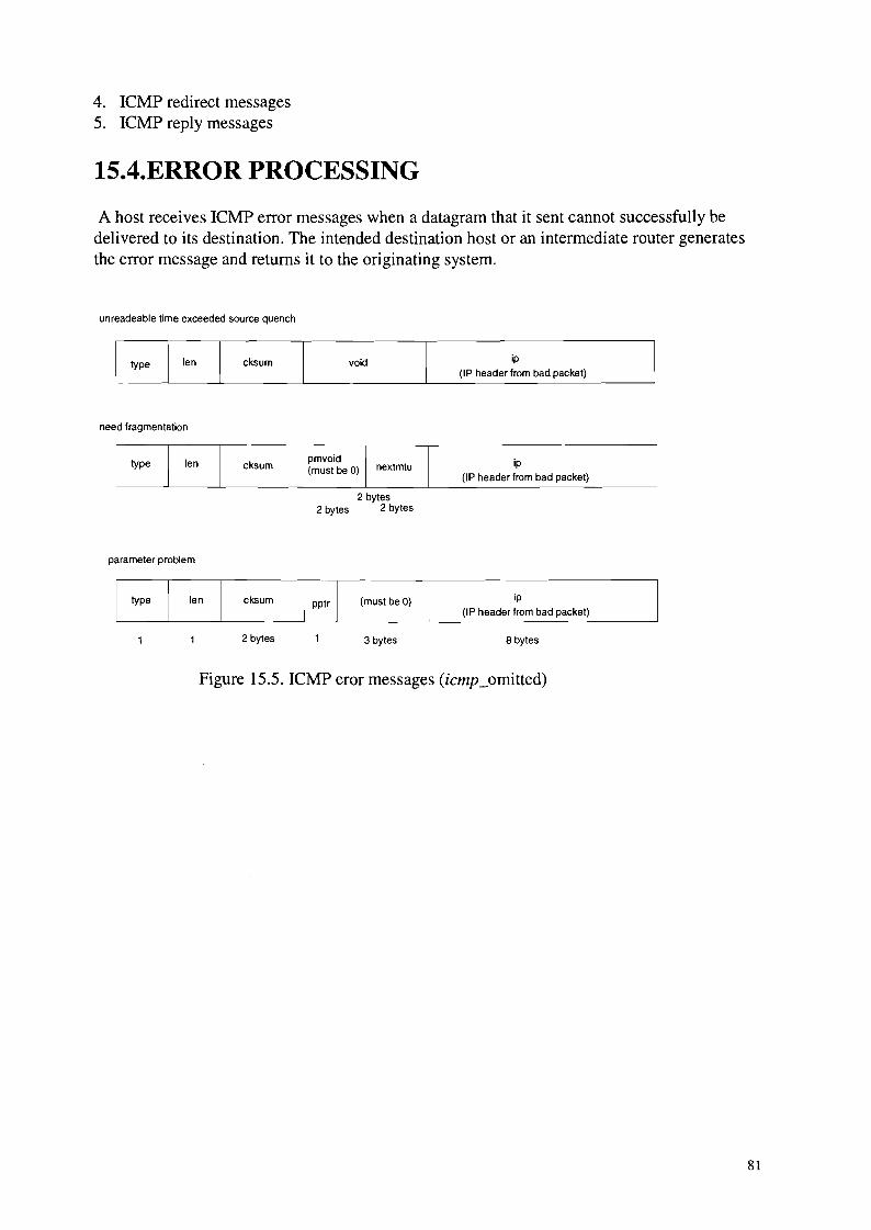
4. ICMP redirect messages5. ICMP reply messages
15.4.ERROR PROCESSING
A host receives ICMP error messages when a datagram that it sent cannot successfully bedelivered to its destination. The intended destination host or an intermediate router generatesthe error message and returns it to the originating system.
unreadeable time exceeded source quench
cksum void ip
(IP header from bad packet)
need fragmentation
c~um ~(IP header from bad packet)
2 bytes2 bytes 2 bytes
parameter problem
cksum
2 bytes
(must beG)
3 bytes
ip
(IP header from bad packet)
8 bytes
Figure 15.5. ICMP eror messages (icmp_omitted)
81
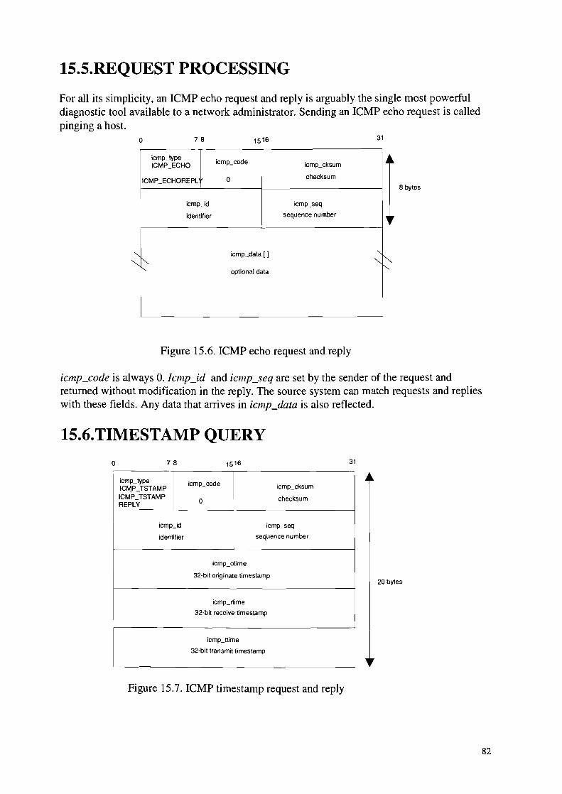
15.5.REQUEST PROCESSING
For all its simplicity, an ICMP echo request and reply is arguably the single most powerfuldiagnostic tool available to a network administrator. Sending an ICMP echo request is calledpinging a host.
o 78 15 16 31
icmp_typeicmp30de .4~
ICMP_ECHO icmp_cksum
ICMP_ECHOREPL 0 checksum
icmp_id icmp_seq
identifier sequence number
"
"'- icmp_data [ 1 "-
"'"~ "~i" optional data
Figure 15.6. ICMP echo request and reply
8 bytes
icmp_code is always O. Icmp_id and icmp_seq are set by the sender of the request andreturned without modification in the reply. The source system can match requests and replieswith these fields. Any data that arrives in icmp_data is also reflected.
15.6.TIMESTAMP QUERY
o 78 15 16 31
icmp_type icmp_code icmp_cksumIC~P_TSTAMPICMP_TSTAMP
0 checksumREPLY
icmp_id icmp_seq
identifier sequence number
icmp_otime
32·bit originate timestamp
icmp_rtime
32-bit receive timestamp
icmp_ttime
32-bit transmit timestamp
Figure 15.7. ICMP timestamp request and reply
20 bytes
82

imcp_code is always O. Icmp_id and icmp_seq serve the purpose as those in the ICMP echomessags. The sender of the request sets icmp_otime (the time the request originated);icmp_rtime (the time the request was received) and icmp_ttime (the time the reply wastransmitted) are set by the sender of the reply. All times are in milliseconds since midnightUTC; the high-order bit is set if the time value is recorded in nonstandard units, as with the IPtimestamp option.
15.7.ADDRESS MASK QUERY
o 7 8 1516 31
icmp_lype icmp30de icmp_cksumICMP_MASKREQICMP_MASKREQ
0 checksumREPLY
icmp_id icmp_seq
identifier sequence number
icmp_mask
32-bit subnet mask
Figure 15.8. ICMP address request and reply
12 by1es
RFC 950 added the address mask messages to the original ICMP specification. They enable todiscover the subnet mask in use on a net work.RFC 1122 forbids sending mask replies unless a system has been explicitly configured as anauthoritative agent for address masks.
15.8.REDIRECT PROCESSINGo 78 31
icrnp_lype icmp_code icmp3ksum
ICMP_REDIRECT0-3 checksum
icmp_gwad.dr
IP address of preferred router
~~ icmp_ip "-~IP header(including options) and at least 8 bytes of original datagram data
Figure 15.9. ICMP redirect message
8 bytes
A redirect message arrives when a packet is sent to the wrong router. The router forwards thepacket to the correct router and sends a ICMP redirect message, which the system incorporatesinto its routing tables.
83

IS.9.REPLY PROCESSING
The kernel does not process any of ICMP reply messages. ICMP requests are generated byprocesses, never by the kernel, so the kernel passes any replies that it receives to processeswaiting for ICMP messages. In addition, the ICMP router discovery messages are passed torip_input.
IS.10.0UTPUT PROCESSING
Outgoing ICMP messages are generated in several ways. IP calls icmp_error to generate andsend ICMP error messages. ICMP reply messages are sent by imcPJeflect, and it is possiblefor a process to generate ICMP messages through the raw ICMP protocol.
Application
IP and ICMP errorstransport protocol
ICMP inputprocessing
, ICMP, replie~ icmp_reflect
icmp~
Figure 15.10. ICMP output processing
15.10.l.icmp_error function
the icmp_error function constructs an ICMP error message at the request of IP or the transportprotocols and passes it to icmpJeflect, where it is returned to the source of the invaliddatagram.We can divide this function in three parts:1. Validate the message2. Construct the header3. Include the original datagram
84

15.10.2.icmpJeflect function
icmp_reflect sends ICMP replies and errors back to the source of the request or back to thesource of the invalid datagram. It is miportant to remember that icmp_reflect reverses thesource and destination addresses in the datagram before sending it.
15.1O.3.icmp_send function
icmp_send processes all outgoing ICMP messages and computes the ICMP checksum beforepassing them to the IP layer.
85

16.Conclusion
Technology is here to stay, as a part of our life regardless of whether we utilize it directly ornot. It is my opinion that with the whole Internet explosion, and so many people using theInternet for so many different reasons. In time it would be as common as eating a pancake,that we can switch off our fridge from the other continent, or possibly even look whether thereis anybody in your room, touching your stereo or not.
As we noticed this system is mainly based on software and I'd rather call our designembedded system than hardware architecture.
We can use this knowledge and these software blocks and translate them to hardware blocksand make the whole concept in silicon.That would be needed as we go further in IP uses in real time systems like conferencing, voiceover IP and other time sensitive applications.
This system is easy to upgrade so it's ready to be used in combination of new protocolsLike, or partially being updated as we hope to exchange the IPv4 with IPv6.
In the route of design we didn't have any problem with the whole concept because the wholeconcept was clear and there were enough study and reference literature to read and use for thisdesign the only thing I actually added to this is creativity and innovating feeling about thewhole concept of designing a system architecture.
We didn't discuss ARP or RARP because of the simple fact that those are more for Ethernetor token ring systems and we just took Ethernet as an example to analyze an interface layerand the needed system calls.As conclusion I have to add that this is a abstract model of a communication hardware systemBased on TCPIIP and we can add or even strip off the system as we like.In integrated systems we can use a bus controller instead of a I/O port or even one Cominterface for the whole system.For systems on.a computers we can add the protocols like IGMP, ARP or RARP to make thesystem works smoothly.
86

Bibliography
1. TCPIIP, second edition, Dr. Sidnie Feit
2. TCPIIP clearly explained, second edition, Peter Loshin,
3. TCPIIP Illustrated volume 1,2 and 3, W.Richards Stevens, Gary R.Wright
4. Ed Taylor, TCPIIP complete
5. Voice and data communication handbook, Regis J.Bates, Donald Gregory
6. Uyless Black, TCPIIP and related protocols,
7. Computer networks, Andrew S. Tanenbaum, (Fourth edition)
8. Data Structure and program design, Robert L.Kruise, (Second edition)
9. Operating systems, Andrew S.Tanenbaum, Albert.S.Woodhull, (Second edition)
10. Pointers on C, Kenneth A.Reek
11. Intel 80386, Lance A.Levental (Dutch translation)
12. The design and implementation of the 4.3 BSD UNIX operation system, SamualJ.Lemer, Marshall Kirk Mckusick, Michael J Karells, John S.Quarterman
13. Adventures in UNIX Network applications programming, Bill Rieken, Lyle Weiman
14. The art of Programming Embedded systems, Jack G.ganssele
15. Intel handbooks:
• peripheral design handbook, 1980
• Peripheral components, 1993
• Memory products, 1993
• Microprocessors, 1993
87


![Designing BEE: a Hardware Emulation Engine for …ultra.usc.edu/assets/002/36603.pdfDesigning BEE: a Hardware Emulation Engine for ... kimmo.kuusilinna@tut.fi ... are available [22]](https://img.pdfslide.net/doc/110x75/5af4df527f8b9a95468e8c55/designing-bee-a-hardware-emulation-engine-for-ultrausceduassets00236603pdfdesigning.jpg)