Embed Size (px)
Citation preview
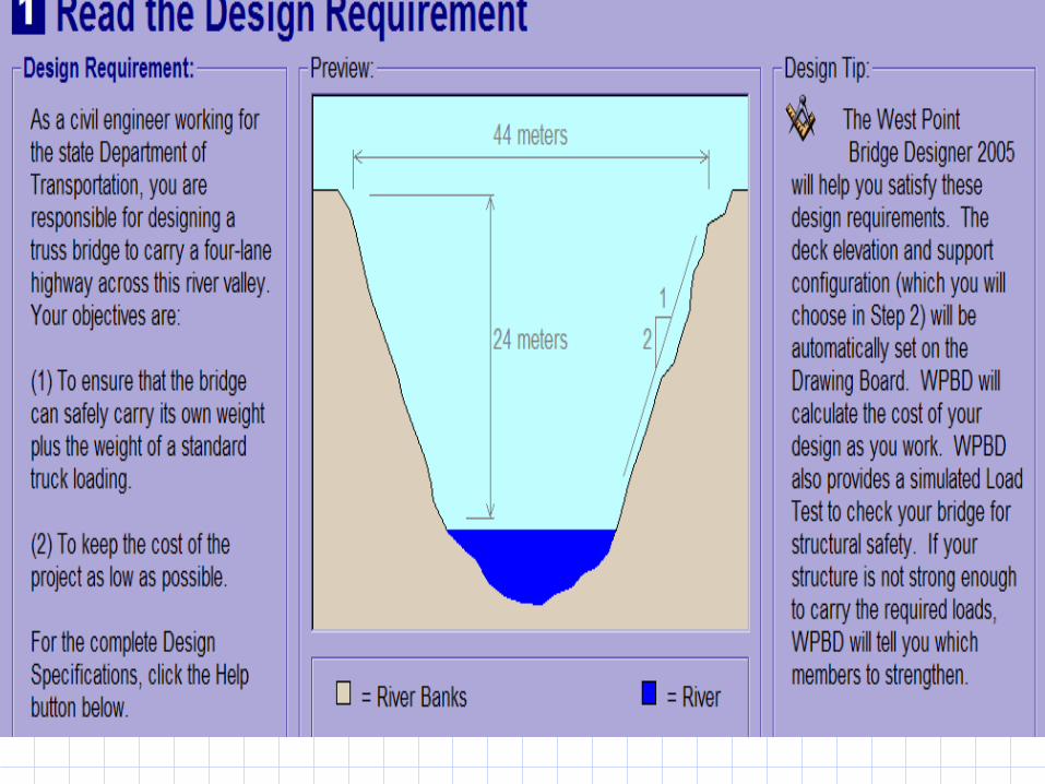
Designing and Building File-Folder Bridges as an Introduction to Engineering Design
Much of the material from:COL Stephen Ressler, P.E., Ph.D.Department of Civil & Mechanical EngineeringU.S. Military Academy, West Point
Why Study Bridges? Apply design process. Large structures need additional design steps,
primarily for safety concerns. Cannot build multiple real structures to test. Cannot test until finished building.
Designs like this need: Computer simulation using physical principles to allow
quick and inexpensive testing of alternate designs. Real world data to put into computer model (e.g.
strength of materials) to ensure accuracy. Models to verify that computer simulation is correct. Means of comparing the model data to the real
structure.
Learn more about forces.
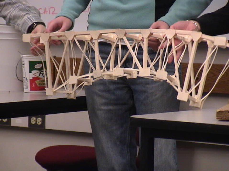
Why use file folders? Inexpensive.Easy to work with.Can make tubes, bars, and gussett
plates that look and act like bridge structures.
Behavior is predictable and compares surprisingly well to steel.
Members are stronger than joints, like in real bridges.
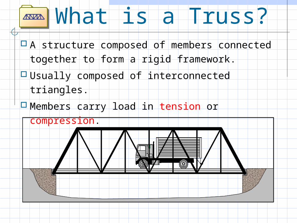
What is a Truss? A structure composed of members connected
together to form a rigid framework.
Usually composed of interconnected triangles.
Members carry load in tension or compression.
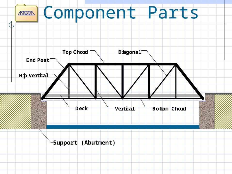
Component Parts
Vertical Bottom Chord
Diagonal
End Post
Hip Vertical
Deck
Top Chord
Vertical Bottom Chord
Diagonal
End Post
Hip Vertical
Deck
Top Chord
Support (Abutment)
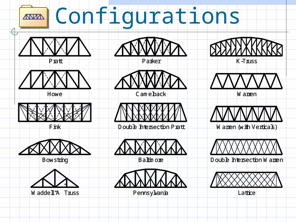
Standard Truss Configurations
Pratt Parker
Double Intersection Pratt
Howe Camelback
K-Truss
Fink
Warren
Bowstring Baltimore
Warren (with Verticals)
Waddell “A” Truss Pennsylvania
Double Intersection Warren
Lattice
Pratt Parker
Double Intersection Pratt
Howe Camelback
K-Truss
Fink
Warren
Bowstring Baltimore
Warren (with Verticals)
Waddell “A” Truss Pennsylvania
Double Intersection Warren
Lattice
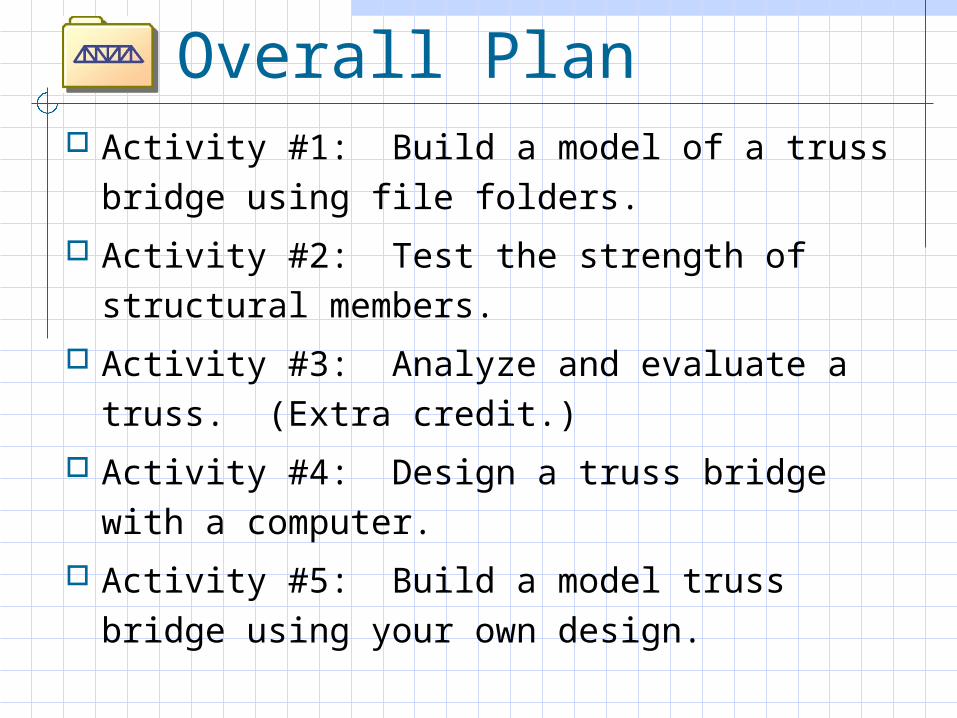
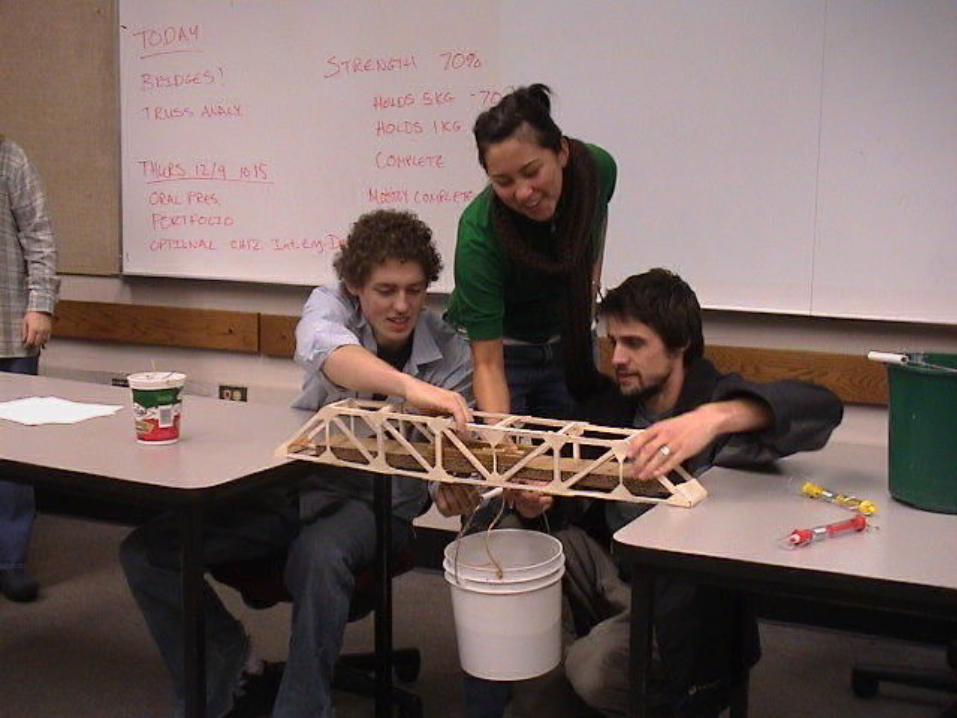
Overall Plan Activity #1: Build a model of a truss bridge
using file folders.
Activity #2: Test the strength of structural members.
Activity #3: Analyze and evaluate a truss. (Extra credit.)
Activity #4: Design a truss bridge with a computer.
Activity #5: Build a model truss bridge using your own design.
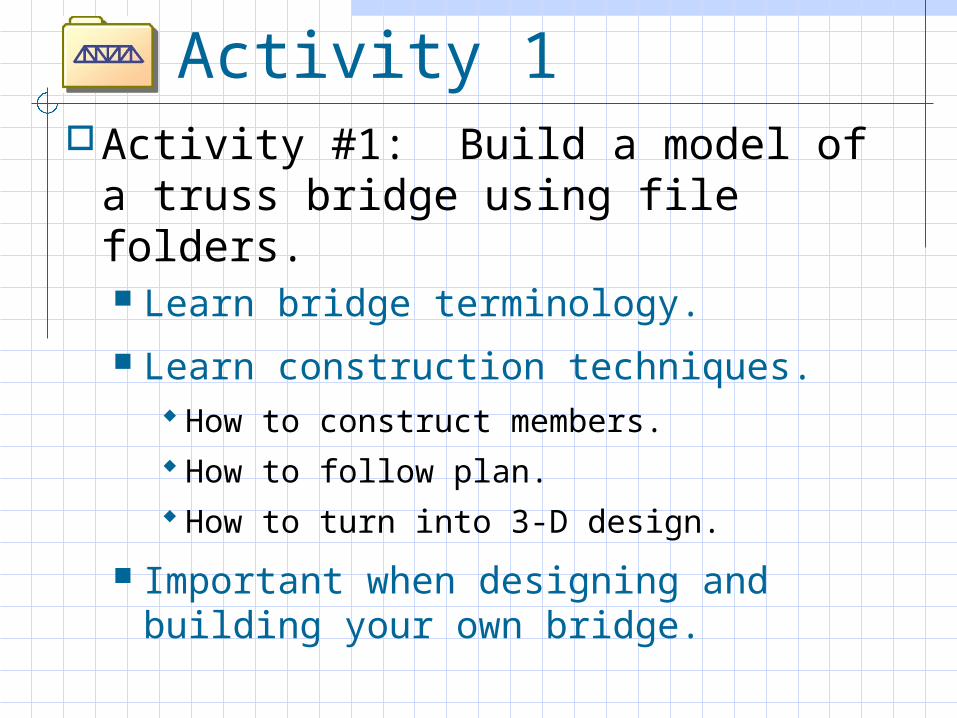
Activity 1Activity #1: Build a model of a truss
bridge using file folders. Learn bridge terminology.
Learn construction techniques. How to construct members. How to follow plan. How to turn into 3-D design.
Important when designing and building your own bridge.
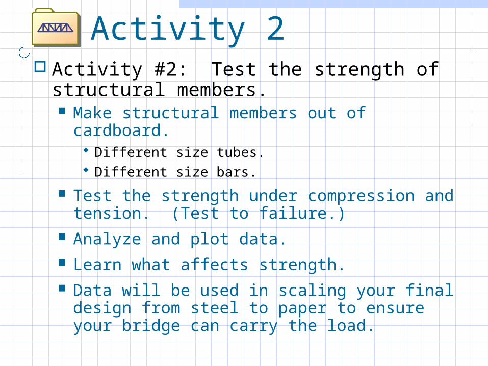
Activity 2 Activity #2: Test the strength of
structural members. Make structural members out of cardboard.
Different size tubes. Different size bars.
Test the strength under compression and tension. (Test to failure.)
Analyze and plot data. Learn what affects strength. Data will be used in scaling your final design
from steel to paper to ensure your bridge can carry the load.
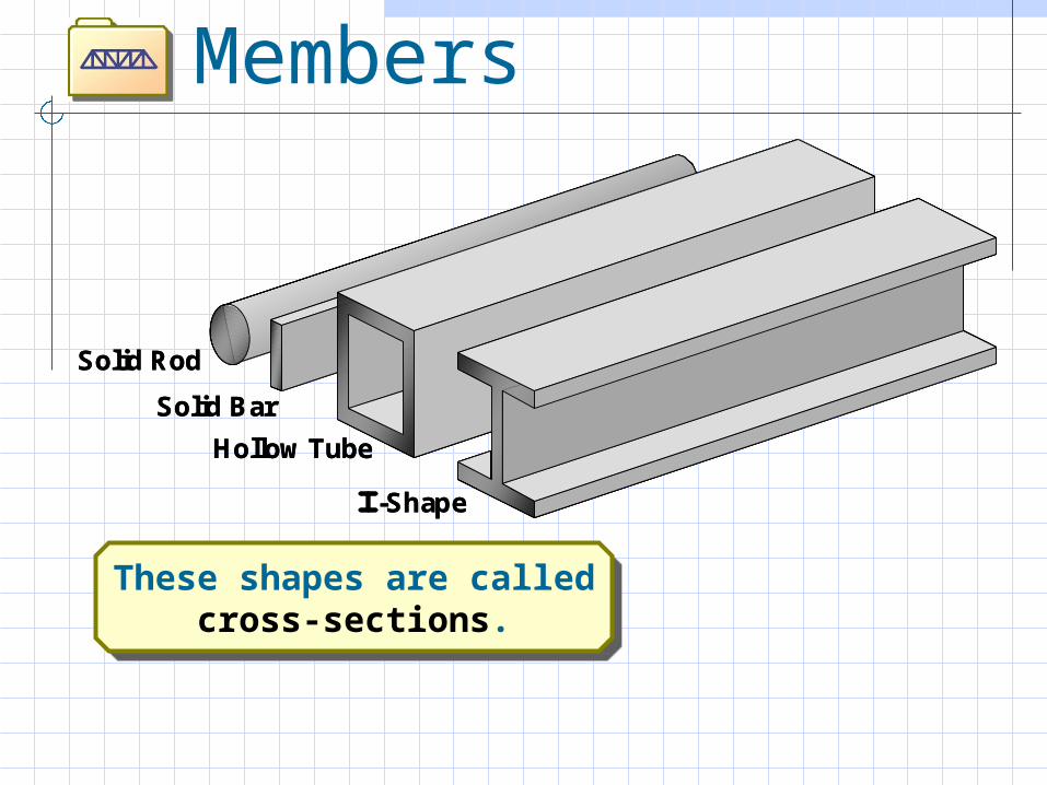
Types of Structural Members
Solid Rod
Solid Bar
Hollow Tube
-Shape
Solid Rod
Solid Bar
Hollow Tube
-Shape
These shapes are calledcross-sections.
These shapes are calledcross-sections.
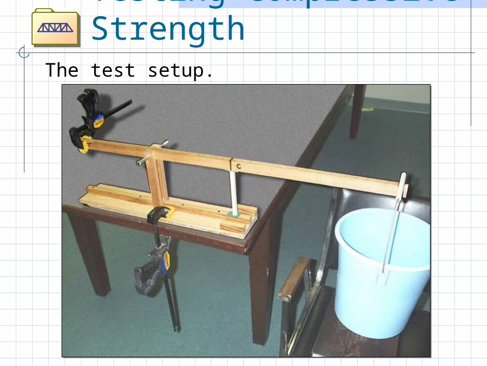
Testing Compressive Strength
The test setup.
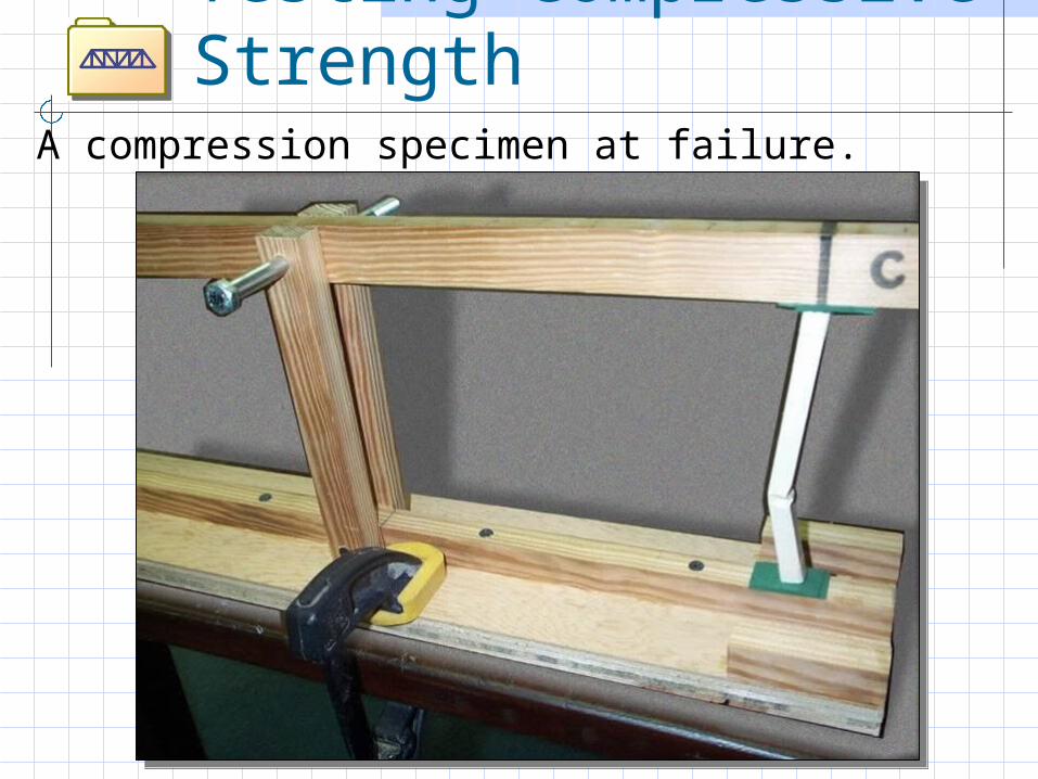
Testing Compressive Strength
A compression specimen at failure.
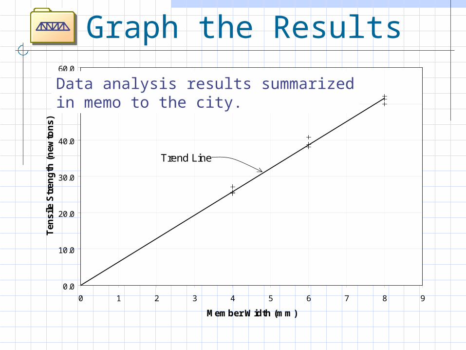
Graph the Results
0.0
10.0
20.0
30.0
40.0
50.0
60.0
0 1 2 3 4 5 6 7 8 9
Member Width (mm)
Ten
sile
Str
eng
th (
new
ton
s)
Trend Line
Data analysis results summarizedin memo to the city.
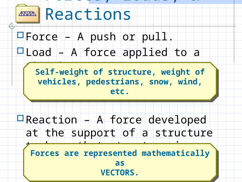
Forces, Loads, & Reactions
Force – A push or pull.Load – A force applied to a structure.
Reaction – A force developed at the support of a structure to keep that structure in equilibrium.
Self-weight of structure, weight of vehicles, pedestrians, snow, wind, etc.
Self-weight of structure, weight of vehicles, pedestrians, snow, wind, etc.
Forces are represented mathematically as
VECTORS.
Forces are represented mathematically as
VECTORS.
Activity 3: Analyze and Evaluate a Truss
May not do, but will at least discuss.Determine internal forces of
compression and tension in the members of a bridge.
Evaluate the safety of a bridge by comparing these forces to the strength of materials we found in Activity 2.
The software will do this analysis for us when we design our own bridges.
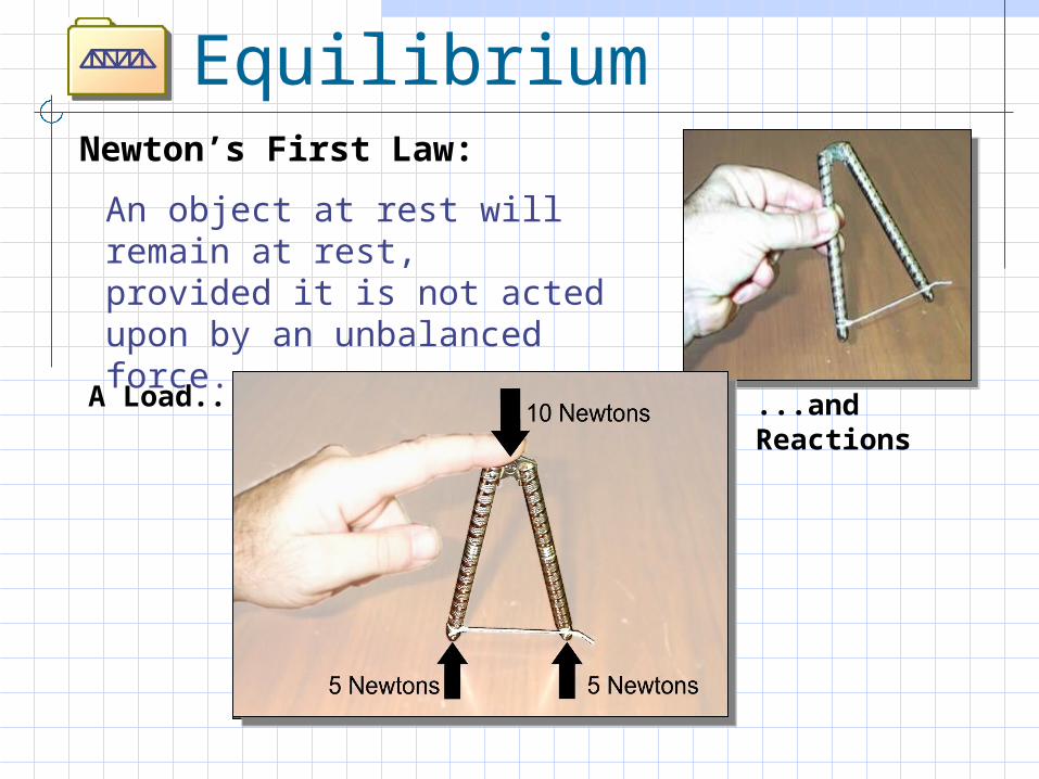
Equilibrium
An object at rest will remain at rest,
provided it is not acted upon by an unbalanced force.
A Load... ...and Reactions
Newton’s First Law:
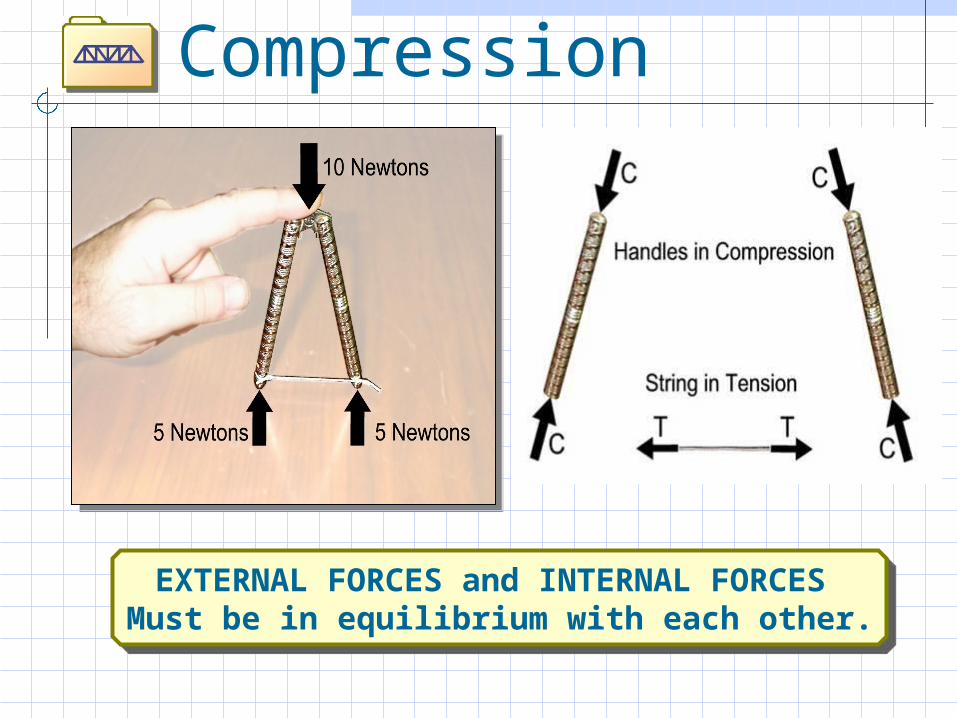
Tension and Compression
EXTERNAL FORCES and INTERNAL FORCES Must be in equilibrium with each other.
EXTERNAL FORCES and INTERNAL FORCES Must be in equilibrium with each other.
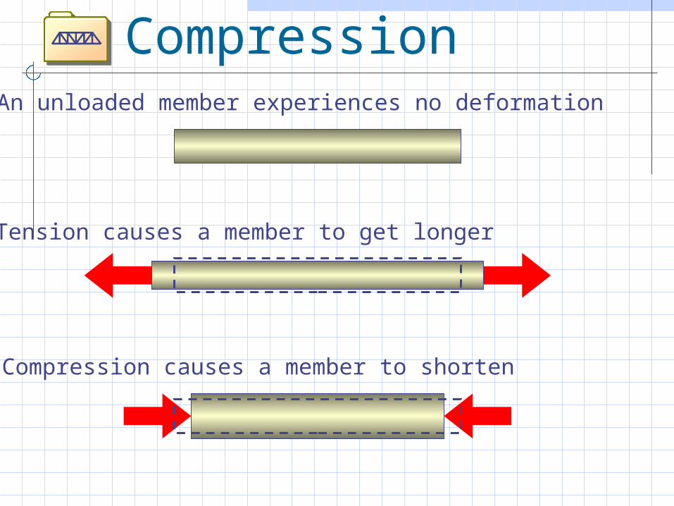
Tension and Compression
An unloaded member experiences no deformation
Tension causes a member to get longer
Compression causes a member to shorten
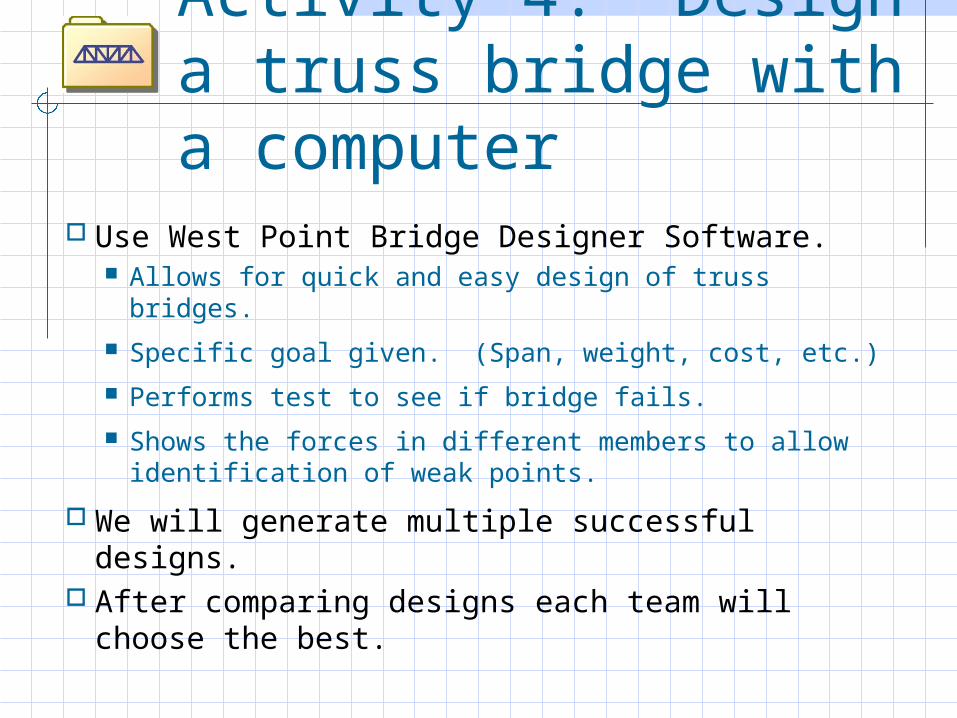
Activity 4: Design a truss bridge with a computer
Use West Point Bridge Designer Software. Allows for quick and easy design of truss bridges.
Specific goal given. (Span, weight, cost, etc.)
Performs test to see if bridge fails.
Shows the forces in different members to allow identification of weak points.
We will generate multiple successful designs. After comparing designs each team will
choose the best.
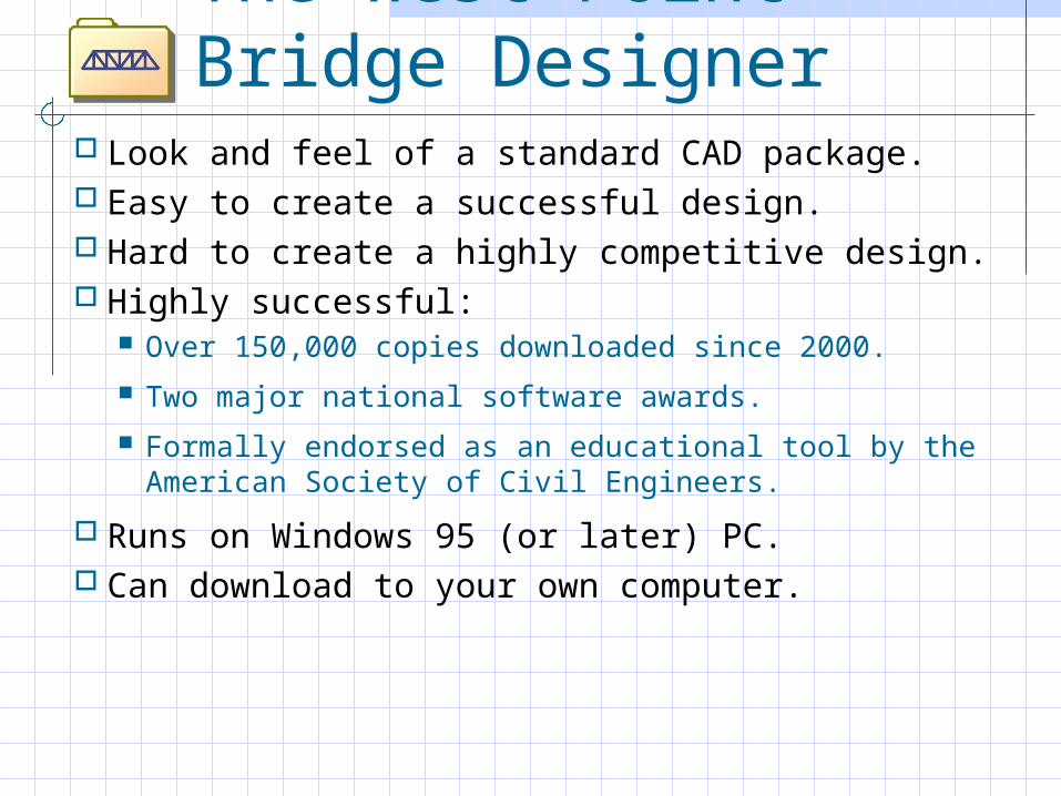
The West Point Bridge Designer
Look and feel of a standard CAD package. Easy to create a successful design. Hard to create a highly competitive design. Highly successful:
Over 150,000 copies downloaded since 2000.
Two major national software awards.
Formally endorsed as an educational tool by the American Society of Civil Engineers.
Runs on Windows 95 (or later) PC. Can download to your own computer.
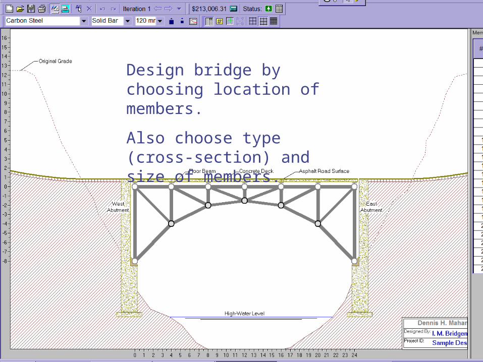
Design bridge by choosing location of members.
Also choose type (cross-section) and size of members.
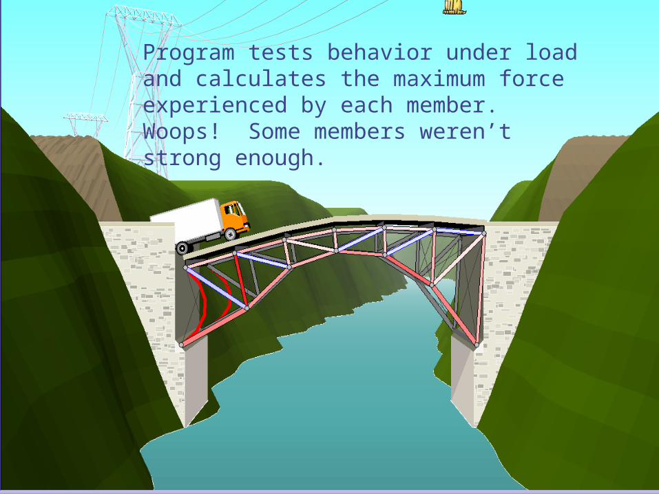
Program tests behavior under loadand calculates the maximum forceexperienced by each member. Woops! Some members weren’t strong enough.
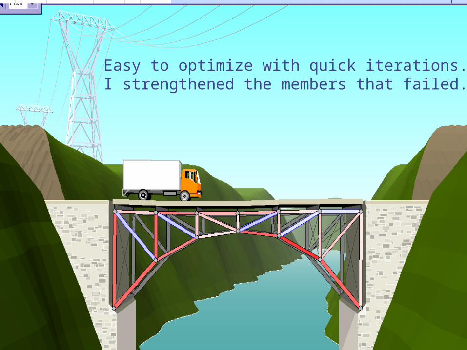
Easy to optimize with quick iterations.I strengthened the members that failed.
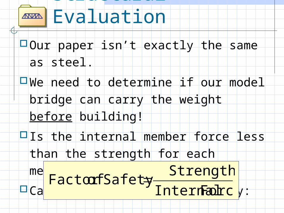
Structural EvaluationOur paper isn’t exactly the same as
steel.
We need to determine if our model bridge can carry the weight before building!
Is the internal member force less than the strength for each member?
Calculate the Factor of Safety:Force Internal
StrengthSafety ofFactor
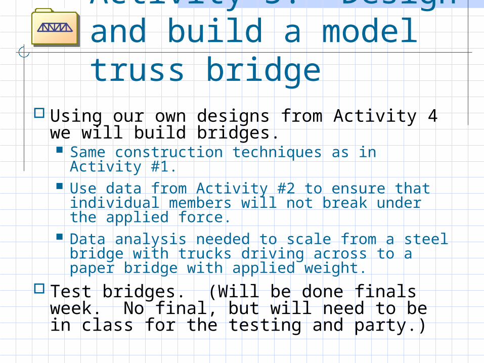
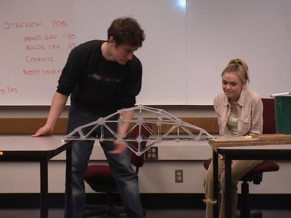
Activity 5: Design and build a model truss bridge
Using our own designs from Activity 4 we will build bridges. Same construction techniques as in Activity #1. Use data from Activity #2 to ensure that
individual members will not break under the applied force.
Data analysis needed to scale from a steel bridge with trucks driving across to a paper bridge with applied weight.
Test bridges. (Will be done finals week. No final, but will need to be in class for the testing and party.)
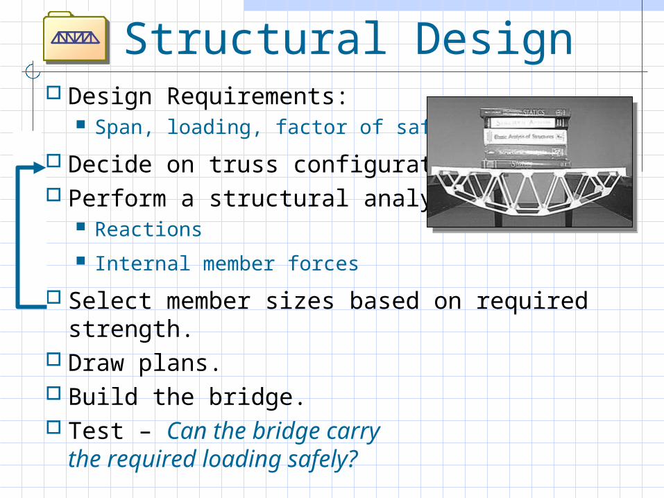
Structural Design Design Requirements:
Span, loading, factor of safety
Decide on truss configuration. Perform a structural analysis.
Reactions
Internal member forces
Select member sizes based on required strength.
Draw plans. Build the bridge. Test – Can the bridge carry
the required loading safely?
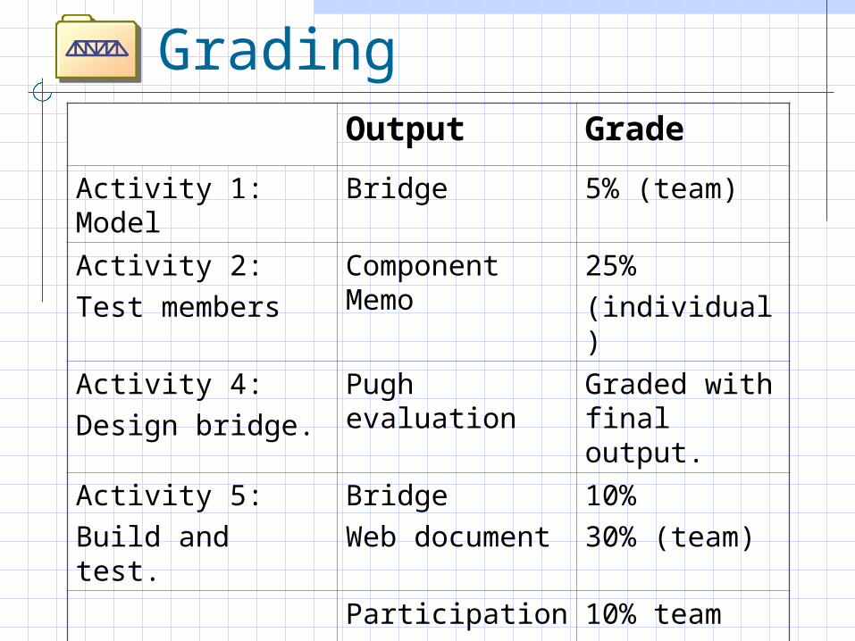
GradingOutput Grade
Activity 1: Model Bridge 5% (team)
Activity 2:Test members
Component Memo
25%(individual)
Activity 4:Design bridge.
Pugh evaluation
Graded with final output.
Activity 5:Build and test.
BridgeWeb document
10%30% (team)
Participation 10% team10% individ.
Reflection 10% (individ.)
Summary File-folder bridges:
Accurate representation of real bridges
Vehicle for learning engineering design concepts.
Design based on authentic applications of math, science, and computer technology.
The West Point Bridge Designer: Experience the engineering design process.
Free!
The West Point Bridge Design Contest: