Embed Size (px)
Citation preview

I
بسم الله الرحمن الرحیم
SUDAN UNIVERSITY OF SCIENCEANDTECHNOLGY College of Graduate Studies
Designing and Implementing a Model for a Microcontroller Controlled Pick and Place
Robotic Arm
متحكم روبوتیة وتوضیع رفع لذراع نموذج وتنفیذ تصمیمالدقیق بالمتحكم فیھا
A THESIS SUBMITTED IN PARTIAL FULFILMENT FOR DEGREE OF M.sc IN MECHATRONICS ENGINEERING
Prepared by: Fadwa Hassan Siddig Supervised by: Dr.Abdalfattah Belal Abd Alslam
December 2014

II
Dedication This thesis is dedicated to: To my wonderful parent and my aunt Majda .
To my cute sister lubna Hassan.
My friends and my family who encourage and support me.
To all people who I love deeply and for all the staff of aeronautical engineering.

III
Acknowledgment In the Name of Allah, the Most Merciful, the Most Compassionate Praise Be to Allah, the Lord of the worlds; and prayers and peace be upon Mohamed His servant and messenger. First and foremost, I must acknowledge my limitless thanks to Allah, the Ever-Magnificent; the Ever- Thankful, for His help and bless. I am totally sure that this work would have never become truth, without His guidance. I am grateful to some people, who worked hard with me from the beginning till the completion of the present research particularly my supervisor Dr. Abdalfatah. I would like to take this opportunity to say warm thanks to all my beloved friends, who have been so supportive along the way of doing my thesis.
I also would like to express my wholehearted thanks to my family for their generous support they provide me throughout my entire life and particularly through the process of pursuing the master degree. Because of their unconditional love and prayers, I have the chance to complete this thesis.

IV
CONTENTS
Page Title II Dedication
III Acknowledgments IV Contents VI List of Figures
VIII List of Tables IX Abstract X Abstract (Arabic)
Chapter One Introduction
١ 1.1 General ٢ 1.2 Research Objectives ٢ 1.3 Project Description ٢ 1. 4 Methodology ٣ 1.5 Thesis layouts
Chapter Two: A theoretical Background
5 2.1 Robotic Arm 5 2.1.1 Robotic arm terminology 6 2.1.2 Robot arm configuration 9 2.1.3 Robot Workspace 9 2.1.4 Robot application
15 2.1.5 Basic robotic system 15 2.1.6 Robotic Arm Grippers 17 2.2 Microcontrollers 18 2.2.1 Microcontroller and Microprocessors 21 2.2.2 Types of Microcontroller 26 2.2.3 Microcontroller Interfacing
27 2.2. 4 Microcontrollers applications 28 2.2.5 Microcontroller Advantages

V
Page
Title
Chapter Three: Hardware 30 3.1 Feature of the robotic arm under design 31 3.2 control circuit 31 3.3 AT mega 16L 32 3.3.1 ATmega16 Architecture 34 3.3.2 Pin Configurations and Description 36 3.3.4 Power supply
37 3.4 ULN2003A
37 3.4.1 Some important features of ULN2003A…
39 3.4.2 Pin connection
39 3.5 Relays 39 3.6 servomotors 41 3.6.1 Types of servomotors
41 36.2 Part of servomotor Chapter Four: Simulation and Result
44 4.1 PROTEUS 45 4-2 BASCOM 45 4.2.1 Writing programs using BASCOM-AVR IDE 46 4.2.2 Program Pick Place 47 4.2.3 BASCOM Code
Chapter five: Conclusion and Recommendation
53 5.1Conclusion 53 5.2 Recommendation 54 References
Appendices

VI
List of Figures
Page Title Figure number 6 Cartesian robotic arm Figure 2-1 7 cylindrical robotic arm Figure 2-2 7 Spherical robotic arm Figure 2-3 8 SCARA robotic arm Figure 2-4 8 Articulated robotic arm Figure 2-5
10 robotic material handlers Figure 2-6 11 Robotic Welding Figure 2-7 11 Robotic assembly Figure 2-8 12 Robotic Dispensing Figure 2-9 13 Biomedical Robotics Figure 2-10 14 NASA Shuttle and International Space
Station Robots Figure 2-11
15 Basic components of computer-controlled robotic arm
Figure 2-12
17 Parallel Jaw Gripper and Angular Jaw Gripper
Figure 2-13
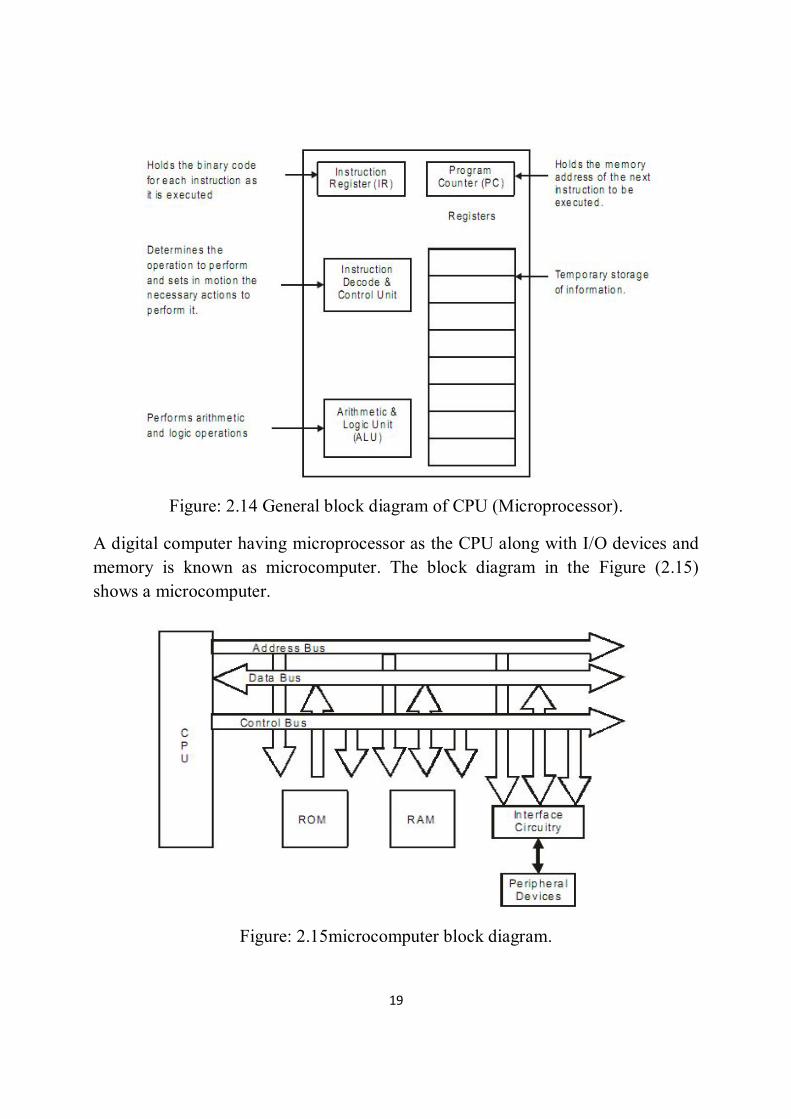
19 General block diagram of CPU (Microprocessor)
Figure 2-14
19 Microcomputer block diagram Figure 2-15 20 A bock diagram of a microcontroller Figure 2-16 21 Types of microcontrollers Figure 2-17 30 Model Figure 3-1 31 Gripper Figure 3-2 32 Control circuit Figure 3-3 36 Pin Configurations Figure 3-4 38 ULN2003A Figure 3-5 39 Relay Figure 3-6

VII
page Title Figure number 40 Servo motor Figure 3-7 40 Part of servo motor Figure 3-8 44 Servo motors driver circuit Figure 4-1 46 Flowchart Figure 4-2 47 Subroutine flowchart Figure 4-3

VIII
List of Tables
Page Title Table number 23 Features of the PIC family Table 2-1 24 AVR 8-Bit Family Table 2-2 24 Features of mega AVR family Table 2-3 25 Features of the 8051 Table 2-4 26 Versions of 8051 from Atmel(All ROM
Flash) Table 2-5
26 Versions of 8051 From Dallas Semiconductor's.
Table 2-6
26 Compares the basic features of the microcontroller
Table 2-7
37 Logic families Table 3-1

IX
Abstract
Robots are used for the most boring and repetitive jobs in manufacturing. The military and police use robots for dangerous jobs, such as manipulating explosive devices. Robots are used in inaccessible places, such as exploring the bottom of the sea. Being simple, cheap, and particularly designed for a specific job, tailored robotic arms are being frequently used in the industry of today. In this research, a model for two degrees of freedom picks and place robotic arm was designed, simulated with Proteus Virtual System Modeling (VSM) software, then built and tested. The model consists of a servomotor which drives a cylindrical link that rotates about its vertical axis, a second motor which drives a rectangular link that rotates about a horizontal axis, and a third servomotor which operate a gripper attached to the rectangular link. The three motors are controlled by an Atmega-16L microcontroller programmed via BASCOM-AVR software. When a start push button was pressed, the arm moved from its home position, picked a piece from a specific place, place it at a target place, and kept repeating this till a stop push button was pressed.

X
المستخلص
الجیش والشرطھ یستخدمون . یستخدم الانسان الالى فى معظم الوظائف المملة والمتكررة فى التصنیع یستخدم الانسان الالى فى الاماكن التى لا . الروبوت فى الوظائف الخطرة مثل التعامل مع المتفجرات
اذرع ، محددةلكونھا بسیطة ورخیصة ومصممة خصیصا لوظیفة .یمكن الوصول الیھا مثل قاع البحرتم تصمیم ، فى ھذا البحث.الانسان الالى المفصلة اصبحت تستخدم بصورة متكررة فى الصناعة الیوم
. وتم نمذجتھا باستخدام حزمة بروتوز كما تم بناءھا واختبارھا. نموذج لذراع حره الحركھ للرفع والتوضیعواخر یدیر وصلة ، ا الرأسىیتكون النموذج من محرك مؤازه یدیر وصلة اسطوانیة حول محمورھ
المحركات الثلاث . مستطیلة الشكل حول محور افقى وثالث لتشغیل ماسكة مثبتة على الوصلة المستطیلة-BASCOMتمت برمجتھ باستخدام البرنامج Atmega-16Lیتم التحكم بھم باستخدام متحكم دقیق نوع
AVR . المسكنى ورفعت قطعة من مكان محدد عند الضغط على زر البدایة تتحرك الذراع من الوضع .ووضعتھا فى المكان المستھدف وظلت تكرر ھذه العملیة حتى تم ضغط زر التوقف
.

XI

1
Chapter one
Introduction

1
Chapter one
Introduction
1.1 General
Today, some of the most boring and repetitive jobs in Manufacturing are done by robots. The military and police use robots for dangerous jobs, such as manipulating explosive devices. Robots are used in inaccessible places, such as exploring our solar system or the bottom of the sea. Robots also appear in entertainment, research, medicine, and education. Mankind is only beginning to see the use and value of robotics. A robot is a machine which has some ability to interact with physical objects and to be given electronic programming to do a specific task or to do a whole range of tasks or actions. It may also have some ability to perceive and absorb data on physical objects, or on its local physical environment, or to process data or respond to various stimuli. A robotic arm is a type of mechanical arm, usually programmable, with similar functions to a human arm; the arm may be the sum total of the mechanism or may be part of a more complex robot. The links of such a manipulator are connected by joints allowing either rotational motion (such as in an articulated robot) or translational (linear) displacement. The links of the manipulator can be considered to form a kinematic chain. The terminals of the kinematic chain of the manipulator is called the end effect or and it is analogous to the human hand. End effectors are the device at the end of robotic arm, designed to interact with the environment. The robot’s use determines the type of end effectors needed. Robotic end effectors can be used in many applications. Robotic hands are being developed to imitate the size, shape, and degrees of freedom of the human hand. The many uses of such a robotic hand include prosthesis, industry, and space exploration, just to name a few. Many robot hands have three fingers to reduce cost and simplify control, such as those needed by industry. Some robots do not ever have fingers, but, instead, have the needed tools directly attached to them. In order to study and replicate the human hand, computer models have been used.

2
1.2 Research Objectives The objective of this research project is to design and implement a complete system model for an inexpensive robotic arm. A model of the robotic arm that allows a user to manipulate an object by picking it from a known position and placing it at a target position, through programmed movements, will be designed, constructed and tested. 1.3 Project Description
This research project includes the following: i. Designing a two degree of freedom robotic arm, to pick an object sensed
by a micro switch at specific position. ii. The arm will be programmed to place the object at a target place within
its work volume, as per the user wish. iii. The arm will be driven by two servomotors controlled via a
microcontroller. iv. The arm work cycle will be initiated by a signal generated by the micro
switch. v. The gripper will be programmed to pick the object, and release it at the
target position; the gripper will drive by a servomotor. vi. This project will not include a kinematic analysis of the arm, though its
theory will be reviewed briefly. vii. The research work will include at interfacing the motors and the micro
switch to the microcontroller, as well as the programming and the user interface of the control computer.
1.4 Methodology
i. Revising robot arm kinematics. ii. Gathering theoretical data on servomotors, microcontrollers programming
and interfacing. iii. Choosing material (type of frame material, microcontroller, motors, and type
of gripper). iv. Design of interfacing circuit. v. Simulator for microcontroller by PROTUES.
vi. Building of physical model of the robotic arm. vii. Testing the model.

3
1.5 Thesis layouts The research was divided into fifth chapters Chapter one is an introduction include the objective and the general idea of the project, then chapter two shows a theoretical background of the robotics arms, chapter three include the hardware of the project’s model , chapter four shows the simulation and result , finally chapter fifth include the conclusion and recommendations.

4
Chapter two A theoretical background

5
Chapter two A theoretical background
2.1 Robotic Arm A robotic arm is a type of mechanical arm, usually programmable, with similar functions to a human arm; the arm may be the sum total of the mechanism or may be part of a more complex robot. Industrial robots usually consist of a jointed arm (multi-linked manipulator) and end effectors that are attached to a fixed surface [1].
Types of robot arms depend on their range, working capability and reach.
2.1.1 Robotic arm terminology:
To study a robotic arm, one will deal with the following terminology.
i. Link:
The solid structural member of the arm.
ii. Joint:
The moving couplings between links. Joint can be either rotary (often driven by electric motors and chain/belt/gear transmissions, or by hydraulic cylinders and levers),or prismatic(slider joint in which a link is supported on a liner bearing, and linearly actuated by ball screws and motors or cylinders) [2].
iii. Degrees of Freedom (DOF):
The degree of freedom is the term that is used to describe a single movement of a joint, which may be a translation (linear motion) or a rotation. The total number of degrees of freedom of a robotic arm is the number of independent movement by which the arm motion can be described. One can typically identify the number of degrees of freedom by the number of actuators on the robot arm. When building a robot arm few degrees of freedom should be allowed for as per the requirement of the application, because each degree requires a motor, often an encoder, and exponentially complicated algorithms and cost [3].

6
v. Payload:
The payload is maximum mass the robot can lift before the robot fails, or there is a dramatic loss of accuracy.
2.1.2 Robot Arm Configuration:
The robot arm is probably the most mathematically complex robot you could ever build.
a. Cartesian robots:
Is used for pick and place work, plotting and handling arc welding. Its range is mostly 2 dimensional showing in Figure( 2.1).
Figure: 2.1 Cartesian robotic arms.
b. Cylindrical robots:
Having a revolute motion about a base, a prismatic joint for height, and a prismatic joint for radius. Is also used for the above mentioned working categories, but since it operates in a cylindrical co-ordinate system, it can be used to do the operations more precisely and accurately furthermore it also has a wider reachable range showing in Figure (2.2).

7
Figure: 2.2 cylindrical robotic arms.
c. Spherical robots:
Having two revolute joint and one prismatic joint allow the robot to point in many directions, and then reach out some radial distance. Works on the polar coordinate system, showing in Figure( 2.3).
Figure: 2.3 Spherical robotic arms.
d.SCARA robots:
The selective compliance arm for robotic assembly (SCARA), conforming to cylindrical coordinates, but the radius and rotation is obtained by two planar links with revolute joint. Is mainly used for pick and place work. It has to parallel rotary

8
joints to provide flexibility in a plane. Then for a three dimensional reach it is usually combined with other mechanisms, showing in Figure (2.4).
Figure: 2.4 SCARA robotic arms.
e. Articulated robots:
Have three rotary joints to position the robot, this robot most resembles the human arm, with a waist, shoulder, elbow, wrist [2], and showing in Figure( 2.5).
.
Figure: 2.5 Articulated robotic arm.

9
2.1.3 Robot Workspace
The robot workspace (sometimes known as reachable space) is all places that the end effectors (gripper) can reach. The workspace is dependent on the DOF angle/translation limitations, the arm link lengths, the angle at which something must be picked up at, etc. The workspace is highly dependent on the robot configuration [3]:
-The DOF angle/translation limitations.
-The arm link lengths.
-The angle at which something must be picked up.
2.1.4 Robot application
Application robots are being used worldwide to increase quality and meet production requirements
1. Industrial robots have been in use for about 50 years. The first industrial robot was used for material handling in General Motors facilities. Nowadays, many different applications can be done by robots. Applications for industrial robots:
a. Robotic handling operation (38%):
Material handling is the most popular application with 38% of operational stock of industrial robots worldwide. Material handling is the process of moving parts and materials. Handling takes place in some form at nearly every step of manufacturing - from production and consumption, to disposal. Used robotic systems have a big impact on material applications. Used material handling robots cut labor spending and speed up production. By installing a used robotic material handling system, your line can run freely without manual intervention, making finished products more consistent, showing in Figure (2.6).

10
Figure: 2.6 robotic material handlers.
b. Robotic Welding (29%):
This segment mostly includes spot welding and arc welding which is mainly used by the automotive industry. Spot welding is still more popular than arc welding but not for long; as arc welding is becoming very popular in the metal industry.
Spot Welding Robots: Spot welding, a type of resistance welding, is the most common welding application found in the manufacturing field. It joins thin metals together when the metals resist the electrical current.
While it is commonly used in the automotive industry to join sheet metal frames together, the spot welding application has a variety of project uses. Spot welding robots have the ability to overcome difficult welds while providing consistent quality. Automating spot welding is quick, easy and a great economic solution. A spot welding robot is cost effective and comes in several models.
Arc Welding Robots: Arc welding utilizes an electric arc between an electrode and a metal base using either consumable or non consumable electrodes. A welding robot is commonly found in steel product and auto move manufacturing. An arc welding robot uses a process which applies intense heat to metal at a joint, causing the metal to melt and intermix. Robot welding has several benefits, including improved weld consistency, decreased cycle times, and enhanced efficiency. The safety advantages of switching to welding robots include reduced health hazards for your workers. From limiting exposure to hazardous

11
fumes to decreased risk of arc burn, arc welding robots help to save workers from a once dangerous job, showing in Figure (2.7).
Figure: 2.7 Robotic Welding.
c. Robotic Assembly (10%):
Assembly robots have expanded production capabilities in the manufacturing world. An assembly line robot can increase production speed and consistency. End can be customized for each assembly robot to cater to the manufacturing requirements and can be used for all applications.
Assembly robotics are used for lean industrial processes. Robots have saved workers from tedious and dull assembly line jobs, while increasing production and savings in the process, it showing in Figure (2.8).
d. Robotic Dispensing (4%): Like painting, gluing, applying adhesive sealing, spraying, etc. Only 4% of the operational robots are doing dispensing, showing in Figure (2.9).

12
Figure: 2.8 Robotic assemblies.
Figure: 2.9 Robotic Dispensing.
2. Biomedical Robotics:
With increasing demands for new and enhanced medical and rehabilitation procedures, the demands on health services worldwide are becoming critical. It is suggested that robots or robot-enabled technologies may have a significant part to play in the future of healthcare. Is used the robot in surgical procedures and use in prosthetics, show Figure (2.10).
a. Robotic Micro-Bio manipulations.
b. Robot-Assisted Microsurgery.
c. robotic neuron-navigation.

13
Figure: 2.10 Biomedical Robotics.
3. Remote operations:
Remote applications for robotics include undersea, nuclear environment, bomb disposal, law enforcement, and outer space [4], show Figure: 2.11.

14
Figure: 2.11NASA Shuttle and International Space Station Robots.

15
2.1.5 Basic robotic system
The basic components of robotic arm are shown in figure: 2.12:
Structure: the mechanical structure (link, base, etc.) requires a great deal of mass to provide enough structural rigidity to ensure high accuracy for different payloads.
Actuators: the stepper motors or servo motors that drive the robot joints. This also includes mechanisms for transmission, locking, etc.
Control computer in this project use microcontroller: to interface with user, control the robot's joints.
Sensors: the sensors are of two types (proximity sensors to sense other objects, and force sensors to enable the robot to apply the exact amount of force when gripping an object. in this project not use sensors.
End of arm tooling (EOAT): provided by the user, and designed for specific tasks [2].
Figure: 2.12 Basic components of computer-controlled robotic arm.
2.1.6 Robotic Arm Grippers
Gripper is an end-of-arm device often used in material handling applications. Generally, the gripper is a device that is capable of generating enough grip force to retain an object while the robot performs a task on the part such a pick-and-place operation. Any gripper must be capable of performing the task of opening and

16
closing with a prescribed amount of force over many years of daily operation The most commonly used grippers are finger grippers[5], [6].
These grippers generally have two opposing fingers or three fingers like a lathe chuck. The fingers are driven together such that once gripped any part is centred in the gripper. This gives some flexibility to the location of components at the pick-up point. Two finger grippers can be further split into parallel motion or angular motion fingers.
A. Angular jaw gripper:
Open and close around a central pivot point, moving in an arcing motion.
An angular gripper is used when there is a need to get the tooling out of the way.
The advantage for an angular gripper falls on its simple design and only requires one power source for activation.
However, it has several disadvantages including jaws that are not parallel and a changing centre of grasp while closing Meanwhile, parallel jaw gripper moves in a motion parallel in relation to the gripper’s body.
B. A parallel gripper:
Is used for pulling a part down inside a machine because the fingers fit into small areas better.
An advantage of parallel type gripper is that the centre of the jaws does not move perpendicular to the axis of motion. Thus, once the gripper is centred on the object, it remains centred while the jaws close. Space constraints might lead to the use of parallel over angular.
Figure 1(a) and Figure 1(b) shows the Parallel Jaw and Angular Jaw gripper.

17
Figure: 2.13 Parallel Jaw Gripper and Angular Jaw Gripper.
For some tasks however where flexible or fragile objects are being handled, the use of either vacuum or magnetic grippers is preferable. With these, the surface of the gripper is placed in contact with the object and either a magnetic field or a vacuum is applied to hold them in contact.
Parallel grippers are typically more accurate than other style grippers.
2.2 Microcontrollers:
Microcontrollers were first considered at Intel in 1969 when a Japanese company approached Intel to build some integrated circuits for calculators. Marcian Huff used his previous experience on the PDP-8 to propose an alternate solution – a programmable IC Frederico Faggin transformed this idea to reality and Intel bought the license from the Japanese company (BUSICOM) to create the 4004 4-bit microprocessor capable of 6000 operations per second. This was soon followed by the 8-bit 8008 in 1972. Intel’s efforts were soon followed by Motorola with the 8-bit 6800 series and MOS Technology introduced the 6501 and 6502 [7].
A microcontroller is a general purpose electronic circuit; it is a full computer inside a single integrated circuit (IC or chip). Normally with an IC like the TDA2822M amplifier or LM386 op amp its function and its pins are fixed, you have no control over what they do, and therefore limited control over how to connect them.
Microcontrollers have only been with us for a few decades but their impact (direct or indirect) on our lives is profound. Usually these are supposed to be just data

18
processors performing exhaustive numeric operations. But their presence is unnoticed at most of the places like, home, supermarkets, office, and industry.
What inside them makes these machines "smart"? The answer is a microcontroller .Creating application for the microcontrollers is different than any other development job in electronics and computing. Before selecting a particular device for an application it is important to understand what the different options and features are and what they can mean with regard to developing the application.
Simply an embedded controller is a controller that is embedded in a greater system. One can define an embedded controller as a controller (or computer) that is embedded into some device for some purpose other than to provide general purpose computing.
2.2.1 Microcontroller and Microprocessors:
A controller is used to control some process. At one time, controllers were built exclusively from logic components, and were usually large, heavy boxes. Later on, microprocessors were used and the entire controller could fit on a small circuit board. This is still common one can find many controllers powered by one of the many common microprocessors.
As the process of miniaturization continued, all of the components needed for a controller were built right onto one chip. A one chip computer, or microcontroller was born A CPU built into a single VLSI chip is called microprocessor. The simplified block diagram of the CPU is shown in the Figure(2.14) It contains arithmetic and logic unit (ALU)Instruction decode and control unit, Instruction register, Program counter(PC), clock circuit (internal or external), reset circuit (internal or external) and registers. For example Intel 8085 is 8-bit microprocessor and Intel 8086/8088 is 16-bit microprocessor. Microprocessor is general-purpose digital computer central processing unit (CPU).The microprocessor is general-purpose device and additional external circuitry is added to make it microcomputer.
19
Figure: 2.14 General block diagram of CPU (Microprocessor).
A digital computer having microprocessor as the CPU along with I/O devices and memory is known as microcomputer. The block diagram in the Figure (2.15) shows a microcomputer.
Figure: 2.15microcomputer block diagram.

20
A microcontroller is a highly integrated chip, which includes on single chip, all or most of the parts needed for a controller, Figure (2.16) showing a bock diagram of a microcontroller.
Figure: 2.16 a bock diagram of a microcontroller.
Comparing between microcontroller and microprocessors:
1. Microprocessor is a single chip CPU, microcontroller contains, a CPU and much of the remaining circuitry of a complete microcomputer system in a single chip.
2. Microcontroller includes RAM, ROM, serial and parallel interface, timer, interrupt schedule circuitry (in addition to CPU) in a single chip.
-RAM is smaller than that of even an ordinary microcomputer, but enough for its applications.
-Interrupt system is an important feature, as microcontrollers have to respond to control oriented devices in real time.
3. Microprocessors are most commonly used as the CPU in microcomputer systems. Microcontrollers are used in small, minimum component designs performing control-oriented activities.
4. Microprocessor instruction sets are ''processing intensive'', implying powerful addressing modes with instructions catering to large volumes of data. Their

21
instructions operate on nibbles, bytes, etc. Microcontrollers have instruction sets catering to the control of inputs and outputs. Their instructions operate also on a single bit.
2.2.2 Types of Microcontrollers:
Microcontrollers can be classified on the basis of internal bus width, architecture, memory and instruction set. Figure (2.17) shows the various types of microcontrollers [8].
Figure (2-17) Types of microcontrollers.
i. The 8-bit microcontroller:
When the ALU performs arithmetic and logical operations on a byte (8-bits) at an instruction, the microcontroller is an 8-bit microcontroller. The internal bus width of bit microcontroller is of 8-bit. Examples of 8-bit microcontrollers are Intel 8051 family and Motorola MC68HC11 family.
ii. The 16- bit microcontroller:
22
When the ALU performs arithmetic and logical operations on a word (16-bits) at an instruction, the microcontroller is an 16-bit microcontroller. The internal bus width of bit microcontroller is of 16-bit. Examples of 16-bit microcontrollers are Intel 8096 family and Motorola MC68HC12 and MC68332 families. The performance and computing capability of 16 bit microcontrollers are enhanced with greater precision as compared to the 8-bit microcontrollers.
iii. The 32- bit microcontroller:
When the ALU performs arithmetic and logical operations on a double word (32-bits) at an instruction, the microcontroller is an 32-bit microcontroller. The internal bus width of 32-bit microcontroller is of 32-bit. Examples of 32-bit microcontrollers are Intel family and Motorola and Intel/Atmel 251 family. See APPENDIXS A
iv. MICROCONTROLLER ARCHITECTURAL FEATURES:
There are mainly two categories of processors, namely, Von-Neumann architecture and Harvard Architecture. These two architecture differ in the way data and programs are stored and accessed.
v. CISC (COMPLEX INSTRUCTION SET COMPUTER) ARCHITECTURE MICROCONTROLLERS:
Almost all of today’s microcontrollers are based on the CISC (Complex Instruction Set Computer) concept. When a microcontroller has an instruction set that supports many addressing modes for the arithmetic and logical instructions, data transfer and memory accesses instructions, the microcontroller is said to be of CISC architecture.
vi. RISC (REDUCED INSTRUCTION SET COMPUTER) ARCHITECTURE MICROCONTROLLERS:
The industry trend for microprocessor design is for Reduced Instruction Set Computers RISC) designs. When a microcontroller has an instruction set that supports fewer addressing modes for the arithmetic and logical instructions and for data transfer instructions, the microcontroller is said to be of RISC architecture.
vii. PIC Microcontrollers:

23
A PIC microcontroller is a single integrated circuit small enough to fit in the palm of a hand. ‘Traditional’ microprocessor circuits contain four or five separate integrated circuits - the microprocessor (CPU) itself, an EPROM program memory chip, some RAM memory and an input/output interface. With PIC microcontrollers all these functions are included within one single package, making them cost effective and easy to use.
From Microchip.
Table 2-1: Features of the some of PIC family.
viii. AVR Microcontrollers:
A commercial range of microcontrollers called ‘AVR’ is available from ATMEL We will start by using the ATTINY26, it has 2kbytes of Flash for program storage, 128 bytes of Ram and 128bytes of EEPROM for long term data storage. From Atmel [9].
AVR 8-Bit Family includes ten basic classifications, depending on the type of application used illustrated in the following table 2-2.
Table 2-2: AVR family.
RAM EPROM Part No
64 bytes 128 bytes ١٢Cxxx 64 bytes 128 bytes PIC12F675 bytes٢٥٦ ٣٦٨ bytes PIC 16F877A bytes ٢٥٦ ١٥٣٦ bytes PIC 18F452
Use Classification Protocols used in wireless radio transmitter. AVR Z-link Used for the general purposes of public control MEGA AVR

24
Table 2-3: Features of mega AVR family.
I/O Port 푉 Max. Operating Freq. (MHz)
Interrupt packaging Flash Part No
٢٣ 2.7-5.5 20 MHz ٢٤ 28/32 4kB AT mega 48 ٢٣ 1.8-5.5 20 MHz ٣٢ ٢٤ 4kB ATmega48A
٢٣ 2.7-5.5 20 MHz ٣٢ ٢٤ 4kB ATmega48P
٢٣ 2.7-5.5 16 MHz ٢ 32 8
Kbytes ATmega8A
٢٣ 4.5-5.5 16 MHz ٢ 28/32 8KB AT mega 8 ٣٥ 4.5-5.5 16 MHz ٣ 40/44 8KB AT
mega8515 ٤٠ 4.5-5.5 16 MHz ٣ 40/44 16KB AT mega 16 35 2.7-5.5 16 MHz ٣ 44 16
Kbytes ATMEGA162
٣٢ 4.5-5.5 16 MHz ٣ 40/44 32 KB AT mega 32
٤٠ 4.5-5.5 16 MHz ٨ 64 64 KB AT mega 64 ٥٣ 4.5-5.5 16 MHz ٨ 64 128
Kbytes ATmega128
ix. 8051 Microcontroller:
features multi. Used for the purposes of public control and is considered the largest advantages in large families and very.
XMEGA AVR
Used for the purposes of public control and is characterized by small size.
Tiny AVR
Processors used to run basic LCD. LCD AVR Has recently been replaced by family. MEGA AT90Sxxxx Used to control IP networks CAN. CAN AVR

25
The Intel MCS-51 (commonly referred to as 8051) is a Harvard architecture, CISC instruction set, single chip microcontroller(µC) series which was developed by Intel in 1980 for use in embedded systems.[1] Intel's original versions were popular in the 1980s and early 1990s and enhanced binary compatible derivatives remain popular today. Intel's original MCS-51 family was developed using NMOS technology, but later versions, identified by a letter C in their name (e.g., 80C51) used CMOS technology and consume less power than their NMOS predecessors. This made them more suitable for battery-powered devices. The family was in 1996 continued with the enhanced 8-bit MCS-151 and the 8/16/32-bit MCS-251 family of binary compatible microcontrollers.[1] While Intel no longer manufactures the MCS-51, MCS-151 and MCS-251 family, enhanced binary compatible derivatives made by numerous vendors remain popular today. Some derivatives integrate a digital signal processor (DSP). In addition to these physical devices, several companies also offer MCS-51 derivatives as IP cores for use in FPGAs or ASICs designs. Table 2-4: Features of the 8051
Feature Quantity
ROM 4K bytes
RAM 128K bytes
Timer 2
I/O pins 32
Serial port 1
Interrupt sources 6
Table 2-5: versions of 8051 from Atmel(All ROM Flash)

26
Packaging 푉 Interrupt Timer I/O pins
RAM ROM Part No
٤٠ 5V ١٢٨ ٣٢ ٢ ٦ 4K AT89C51 ٤٠ 3V ١٢٨ ٣٢ ٢ ٦ 4K AT89LV51 ٤٠ 3V ٦٤ ١٥ ١ ٣ 1K AT89C1051 ٤٠ 3V ١٢٨ ١٥ ٢ ٦ 2K AT89C2051 ٤٠ 5V ١٢٨ ٣٢ ٣ ٨ 8K AT89C52 ٤٠ 3V ١٢٨ ٣٢ ٣ ٨ 8K AT89LV52
Table 2-6: Versions of 8051 From Dallas Semiconductor's soft Microcontroller.
Packaging 푉 Interrupt Timer I/O pins
RAM ROM Part No
٤٠ 5V ١٢٨ ٣٢ ٢ ٦ 8K DS5000-8 ٤٠ 5V ١٢٨ ٣٢ ٢ ٦ 32K DS5000-32 ٤٠ 5V ٢ ٦ 32 ٦٤ 8K DS5000T-8 ٤٠ 5V ١٢٨ ٣٢ ٢ ٦ 32K DS5000T-
32
The following table 2-7: compares the basic features of the microcontroller:
PIC AVR 8051 Max Frequency 20 MHZ 16 MHZ 24 MHZ Cycle 4cycle 1cycle 12cycle IPS 20/4=5MIPS 16/1=16MIPS 24/12=2MIPS Instruction No 35 132 215 memory 64KB 256KB 32KB Architectural RISC/Harvard RISC/Harvard CISC/Von-
Neumann Address bus 12 bit 16 bit 8 bit

27
2.2.3 Microcontroller Interfacing
Developing embedded systems that interface microcontrollers to the outside world is a fascinating endeavor. Such systems require both hardware and software development. Most of the literature covers the programming of the microcontrollers. There does not seen to be as much that describes the practical aspects of designing the circuits that interact with the outside world.
To Interfacing motor with microcontroller by using:
1-ULN2003.
2-L293D:
The maximum current capacity of L293 is 600mA/channel. So do not use a motor that consumes more than that.
The supply voltage range of L293 is between 4.5 and 36V DC. So you can use a motor falling in that range. 2.2.4 Microcontrollers applications:
In addition to control applications such as the home monitoring system, microcontrollers are frequently found in embedded applications. Among the many uses that you can find one or more microcontrollers: automotive applications, appliances (microwave oven refrigerators, television and VCRs, stereos), automobiles (engine control, diagnostics, climate control), environmental control (greenhouse, factory, home), instrumentation, aerospace and thousands of other uses.
Microcontrollers are used extensively in robotics. In this application, many specific tasks might be distributed among a large number of microcontrollers in one system. Communications between each microcontroller and a central, more powerful microcontroller (or microcomputer, or even large computer) would enable information
to be processed by the central computer, or to be passed around to other microcontroller in the system.

28
A special application that microcontrollers are well suited for is data logging. By stick one of these chips out in the middle of a corn field or up in a balloon, one can monitor and record environmental parameters (temperature, humidity, rain, etc). Small size low power consumption and flexibility make these devices ideal for unattended data monitoring and recording.
2.2.5 Microcontroller Advantages:
Microcontrollers are widely used in today’s control systems for the following reasons:
1-Design and Simulation – Because you are programming with software, detailed simulations may be performed in advance to assure correctness of code and system performance.
2-Flexibility – Ability to reprogram using Flash, EEPROM or EPROM allows straightforward changes in the control law used.
3-High Integration – Most microcontrollers are essentially single chip computers with on-chip processing, memory, and I/O. Some contain peripherals for serial communication and reading analog signals (with an analog-to-digital converter or ADC). This differentiates a microcontroller from a microprocessor .Microprocessors require that this functionality be provided by added components.
4-Cost – Cost savings come from several locations. Development costs are greatly decreased because of the design/flexibility advantages mentioned previously because so many components are included on one IC, board area and component savings are often evident as well.
5-Easy to Use – Just program and go! While in the past, programming has often involved tedious assembly code, today C compilers are available for most microcontrollers. Microcontrollers often only require a single 5V supply as well which makes them easier to power and use.[9]

29
Chapter Three Hardware

30
Chapter Three Hardware
3.1 Feature of the robotic arm under design
a. The arm has three servo motors which are controlled through the use of only one microcontroller AtMega 16.
b. The arm could grab things approximately in a hemisphere of 365 mm and is robot made completely with a Perspex material.
The workspace R=퐿 + 퐿
R =210+155=365 mm
c. The arm could lift objects of eight up to 10 mg.
d. The base is directly coupled to a servomotor which provides the vertical axis motion of the first degree of freedom.
e. The second degree of freedom is provided by the arm which is directly coupled to a servomotor which provides the horizontal axis motion.
f. Keeping the design of robotic arm gripper simple, as well as implementing the gripping mechanism using gears and with one servo motors.
Figure: 3.1Gripper.

31
Figure: 3.2 models.
3.2 control circuit
The control circuit which is shown in figure (3.3) is composed of an AtMega16 microcontroller, three servomotors, a current amplifying chip, and a relay.
3.3 AT mega 16L
The ATmega16L is a low-power CMOS 8-bit microcontroller based on the AVR enhanced RISC Architecture. By executing powerful instructions in a single clock cycle, the ATmega16L achieves throughputs approaching 1 MIPS per MHz allowing the system designed to optimize power consumption versus processing speed [15].

32
Figure: 3.3 control circuit.
AT mega 16L stands for:
AT: Is the abbreviation for the name of the manufacturer ATMEL.
Mega: The family that belongs to the microcontroller.
16: This number reflects the size of the program memory and can be: 8,16,32,..256.
L: low voltage (2.7-5.5V).see Appendices A
3.3.1 ATmega16 Architecture:
Our microcontroller, the Atmel ATmega16 integrates memory, clock, a central processing unit, input/output, timers, and an analogy to digital converter.
i. Memory:
Memory on a microcontroller can be used to store data and/or the program to be run. There are often several types of memory on a microcontroller:

33
● Random Access Memory (RAM).
● Read Only Memory (ROM).
● Programmable Read Only Memory (PROM):
◦ Erasable Programmable Read Only Memory (EPROM).
◦ Electronically Erasable Programmable Read Only Memory (EEPROM).
◦ Flash Memory – a type of EEPROM.
RAM can be either read and write, this usually happens quite fast. Data stored on a microcontroller is often stored in RAM. However, the data stored in RAM is volatile which means that it is lost when power is turned off. ROM is non-volatile and therefore stored between power cycles, but may not be written to.
PROM is therefore a compromise between these two types of memory. PROM is nonvolatile and also allows a user to program it at least once. Some PROM may be erased by exposure to UV light, but more common today is EEPROM.
EEPROM allows read and write access and is also non-volatile, but the sacrifice here is that data transfers take much longer than with RAM.
Flash memory is a type of EEPROM. Program memory (where the program is stored) on the ATmega16 is Flash memory. This is also the same as the memory used in digital cameras and cell phones. Data transfer using flash is much faster than EEPROM because it works in blocks of bytes instead of single bytes. This makes it perfect for program memory in our case.
ii. Clock:
The ATmega16 we use is run off an 8 MHz crystal oscillator. The rate of instruction execution is fixed and synchronized by this clock. However, this does not mean that each instruction takes 125 nsec. Different instructions require a different number of cycles.

34
iii.CPU:
This is brains of the microcontroller – the CPU executes instructions such as add, move, jump, multiply, etc. To do so, it must first fetch the instruction and any required data over its data bus.
iv. Input/output (I/O):
The ATmega16 offers 32 programmable I/O lines with 4 8-bit ports. By programming specific registers on the ATmega16, these lines may be set to input, output, or some secondary function. If a pin is set as output, setting the corresponding bit in the output register to 1 will output 푉 on that pin and 0 will output ground. If the pin is set to input, it is possible to read either a 1 or 0 on that pin. These pins act just like memory locations so all that is required to output a value is setting a bit in a memory register. To read a pin, all you need to do is read a bit in a register.
v. Timers:
Timers are internal clocks (2 8-bit timers and 1 16-bit timer is included in the ATmega16). Each timer can be scaled by some factor from the system clock (8 MHz as mentioned previously). These timers can then give us a sense of time and duration – information of great importance in digital control systems. In most cases, you’ll just use a timer to count from 0 to 255 (for an 8-bit timer) or 0 to 65536 (for a 16-bit time).In addition, many interrupts can be triggered off of timers. An interrupt is a piece of code triggered by a particular event. That event might be a timer overflowing, or reaching a particular value.
vi. Analog-to-Digital Converter (ADC). [7]
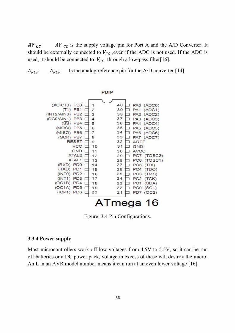
3.3.2 Pin Description and Configurations:
Pin configurations show in Figure( 3.4).
VCC digital supply voltage.
GND Ground.
Port A(PA7..PA0) port A serves as the analog inputs to the A/D converter. Port A also serves as an 8-bit bi-directional I/O port, if the A/D converter is not used.

35
Port pins can provide internal pull-up resistor (selected for each bit). the port A output buffers have symmetrical drive characteristics with both high sink and source capability.
When pins PA0 to PA7are used as inputs and are externally pulled low ,they will source current if the internal pull-up resistors are activated. The Port A pins are tri-stated when a reset condition become active, even if the clock is not running.
Port B(PB7..PB0) Port B is an 8-bit bi-directional I/O port with internal pull-up resistors(selected for each bit). The Port B output buffers Have symmetrical drive characteristics with both high sink and source capability. As inputs, Port B pins that are externally pulled low will source current if the pull-up resistors are activated. The Port B pins that are externally pulled low will source current if the pull-up resistors are activated. The Port B pins are tri-stated when a reset condition becomes active ,even if the clock is not running.
Port B also serves the functions of various special features of the AT mega 16 .
Port C (PC7..PC0) Port C is an 8-bit bi-directional I/O port with internal pull-up resistors (selected for each bit). The Port C output buffers have symmetrical drive characteristics with both high sink and source capability. As inputs, Port C pins that are externally pulled low will source current if the pull-up resistors are activated. The Port C pins are tri-stated when a reset condition becomes active ,even if the clock is not running.
Port D(PD7..PD0) Port D is an 8-bit bi-directional I/O port with internal pull-up resistors(selected for each bit). The Port D output buffers have symmetrical drive characteristics with both high sink and source capability. As inputs, Port D pins that are externally pulled low will source current if the pull-up resistors are activated . The Port D pins are tri-stated when a reset condition becomes active, even if the clock is not running.
RESET Reset Input. A low level on this pin for longer than the minimum pulse length will generate a reset, even if the clock is not running.
XTAL1 Input to the inverting Oscillator amplifier.
XTAL2 Output from the inverting Oscillator amplifier.
36
푨푽푪푪 퐴푉 is the supply voltage pin for Port A and the A/D Converter. It should be externally connected to 푉 ,even if the ADC is not used. If the ADC is used, it should be connected to 푉 through a low-pass filter[16].
퐴 퐴 Is the analog reference pin for the A/D converter [14].
Figure: 3.4 Pin Configurations.
3.3.4 Power supply
Most microcontrollers work off low voltages from 4.5V to 5.5V, so it can be run off batteries or a DC power pack, voltage in excess of these will destroy the micro. An L in an AVR model number means it can run at an even lower voltage [16].
37
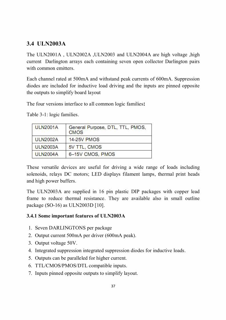
3.4 ULN2003A
The ULN2001A , ULN2002A ,ULN2003 and ULN2004A are high voltage ,high current Darlington arrays each containing seven open collector Darlington pairs with common emitters.
Each channel rated at 500mA and withstand peak currents of 600mA. Suppression diodes are included for inductive load driving and the inputs are pinned opposite the outputs to simplify board layout
The four versions interface to all common logic families:
Table 3-1: logic families.
These versatile devices are useful for driving a wide range of loads including solenoids, relays DC motors; LED displays filament lamps, thermal print heads and high power buffers.
The ULN2003A are supplied in 16 pin plastic DIP packages with copper lead frame to reduce thermal resistance. They are available also in small outline package (SO-16) as ULN2003D [10].
3.4.1 Some important features of ULN2003A
1. Seven DARLINGTONS per package 2. Output current 500mA per driver (600mA peak). 3. Output voltage 50V. 4. Integrated suppression integrated suppression diodes for inductive loads. 5. Outputs can be paralleled for higher current. 6. TTL/CMOS/PMOS/DTL compatible inputs. 7. Inputs pinned opposite outputs to simplify layout.

38
3.4.2 Pin connection
ULN2003A pin configuration while the pin configuration is found in
Appendices C.
Figure: 3.5 ULN2003A.
3.5 Relays:
A relay is an electrical switch that uses an electromagnet to move the switch from the off to one position instead of a person moving the switch. It takes a relatively small amount of power to turn on a relay but the relay can control something that draws much more power [17] showing in Figure (3.6) .Appendices B

39
Figure: 3.6 relay.
3.6 servomotors
A servomotor based on the design of a conventional DC motor, with the addition of an amplifier and a feedback device. The components of a servomotor are shown in figure (3.7). Servomotors are used for angular positioning, such as in radio control airplanes, robotics, CNC machinery or automated manufacturing. They typically have a movement range of 180 degree but can go up to 210 degree. The output shaft of a servo does not rotate freely, but rather is made to seek a particular angular position under electronic control. They are typically rated by torque and speed. A servo rated 40 ounce-in/.21 means that at 1 inch from the hub, the servo can exert 40 ounces of force and move 60 deg in 0.21 sec.
Servomotors and are constructed out of basic DC motors, by adding:
1. Some gear reduction.
2. A position sensor for the motor shaft.
3. An electronic circuit that controls the motor's operation.
Figure: 3.7 servomotors.

40
The Servomotors come with two wires or leads. Two of these wires are to provide ground and positive supply to the servo DC motor. The red wire is the DC supply lead and must be connected to a DC voltage supply in the range of 4.8 V to 6V. The black wire is to provide ground.
3.6.1 Types of Servomotors:
There are two types of servo motors
a. Standard servo:
Motor can rotation of 0-120 and 180 degrees in both directions clockwise and counter-clockwise.
b. Continuous servomotor:
Capable of rotation from 0-360 degree clockwise and counter-clockwise.
a potentiometer (variable resistor) measures the position of the output shaft at all times so the controller can accurately place and maintain its setting.
3.6.2 Part of servomotor
Part of servomotor showing in Figure (3.8).
Figure: 3.8 part of servo motor.

41
Consists of four parts:
1. Small electric DC motor.
2. Position feedback Potentiometer (closed loop system).
3. Reduction gear:
Overdrive and increase torque.
4. Actuator.
A servo motor mainly consists of a DC motor, gear system, a position sensor which is mostly a potentiometer, and control electronics. The DC motor is connected with a gear mechanism which provides feedback to a position sensor which is mostly a potentiometer. From the gear box, the output of the motor is delivered via servo spline to the servo arm. The potentiometer changes position corresponding to the current position of the motor. So the change in resistance produces an equivalent change in voltage from the potentiometer.
Principle strengths:
1. High performance.
2. Small size.
3. Wide variety of components.
4. High speeds available with specialized controls.
Principle weaknesses:
1. Slightly higher cost.
2. High performance limited by controls.
3. High speed torque limited by commentator or electronics.

42
Chapter Four Simulation and Result

43
Chapter Four Simulation and Result
4.1 PROTEUS:
Proteus Virtual System Modeling (VSM) software Offers the ability to co-simulate both high and low-level micro-controller code in the context of a mixed-mode SPICE circuit simulation. It combines mixed mode SPICE circuit simulation, animated components and microprocessor models to facilitate co-simulation of complete micro-controller based designs.
With VSM, it is possible to develop and test such designs before a physical prototype is constructed [11].
Proteus VSM uses ISIS schematic capture software to provide the environment for design entry and development. The ISIS software combines ease of use with powerful editing tools. It is capable of supporting schematic capture for both simulation and PCB design. Designs entered in to Proteus VSM for testing can be net-listed for PCB layout either with Proteus PCB Design products or with third party PCB layout tools. ISIS also provides a very high degree of control over the drawing appearance, in terms of line widths, fill styles, fonts, etc. These capabilities are used to provide the graphics necessary for circuit animation.
PROTEUS: servomotors driver circuit
A simulation of servomotors driver circuit is shown in figure (4.1) .
Figure: 4.1servomotors driver circuit.

44
4-2 BASCOM:
Microcontrollers, such as the AVR, are controlled by software and they do nothing until they have a program inside them.
The AVR programs are written on a PC using the BASCOM-AVR.
This software is a type of computer program called a compiler.
The AVR is connected to the PC with a 5 wire cable. Such a development environment supports the whole process from Coding and testing a program to programming the used microcontroller.
4.2.1 Writing programs using BASCOM-AVR IDE
BASCOM-AVR is four programs in one package, it is known as an integrated development environment (IDE); it includes the Program Editor, the Compiler, the Programmer and the Simulator all together.
This is a typical first program to test your hardware every line of the code is important:
$regfile=”atmega16.dat”, Bascom needs to know which micro is being used as each micro has different features.
$crystal=1000000, Bascom needs to know the speed at which our microcontroller is setup internally so that it can calculate delays such as waitms properly (1 million operations per second)
Config porta=output, each I/O must be configured to be either an input or output; it cannot be both at once .
DO and LOOP statements enclose code which is to repeat; when programming it is important to indent (tab) code within loops; this makes your code easier to follow (this is a code of practice).
Port A = &B10000000 make porta.7 high and make all the other 7 output pins on that port low.
Port A = 0 make all 8 pins on port A low [13]

45
4.2.2 PROGRAM PICKPLACE
• Loop:
• Move to P1 (a general safe position).
• Move to P2 (an approach to P3).
• Move to P3 (a position to pick the object).
• Close gripper.
• Move to P4 (an approach to P5).
• Move to P5 (a position to place the object).
4.2.3 Flowchart
Two flowchart one for main program and other for subroutine in figure (4.2) and figure (4.3).

46
Main Program Flowchart
Figure: 4.2 Main Flowcharts.

47
Subroutine Program Flowchart
Figure: 4.3 Subroutine Flowcharts.

48
4.2.3 BASCOM CODE
$regfile = "m16def.dat"
$crystal = 8000000
Config Portd.1 = Output
Config Portd.2 = Output
Config Portd.3 = Output
Config Portd.4 = Output
Config Portd.5 = Output
Config Portd.6 = Output
Config Portd.7 = Output
Config Pina.0 = Input
Dim X As Word
Do
Gosub Ligun
Gosub Stoprobo
Gosub Gropen
Gosub Stoprobo
Gosub Grclose
Gosub Stoprobo
Gosub Ligov
Gosub Stoprobo
Gosub Rotrihg
Gosub Stoprobo

49
Gosub Ligun
Gosub Stoprobo
Gosub Gropen
Gosub Stoprobo
Gosub Grclose
Gosub Stoprobo
Gosub Ligov
Gosub Stoprobo
Gosub Rotlif
Gosub Stoprobo
Waitms 1000
Loop
Stoprobo:
Portd.4 = 0
Portd.5 = 0
Portd.3 = 0
Portd.2 = 0
Portd.7 = 0
Portd.6 = 0
Waitms 1000
Return
Gropen:
Portd.7 = 0

50
Portd.6 = 1
Waitms 700
Return
Grclose:
Portd.7 = 1
Portd.6 = 0
Waitms 1500
Return
Ligov:
Portd.2 = 1
Portd.3 = 0
Waitms 400
Return
Ligun:
For X = 1 To 5
Portd.2 = 0
Portd.3 = 1
Waitms 50
Portd.2 = 0
Portd.3 = 0
Waitms 500
Next X
Return
51
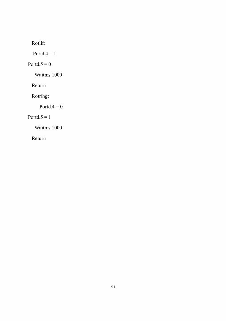
Rotlif:
Portd.4 = 1
Portd.5 = 0
Waitms 1000
Return
Rotrihg:
Portd.4 = 0
Portd.5 = 1
Waitms 1000
Return

52
Chapter five
Conclusion
and Recommendation

53
Chapter five
Conclusion and recommendation
5.1Conclusion In this project a two degrees of freedom pick and place robotic arm was designed simulated, built and tested.
The design interfacing microcontroller ATmega 16 with three servomotors derived by ULN2003, the circuit was simulated with PROTEUS, and the control program code was written with BASCOM. .
5.2 Recommendation
1. Design with 6 DOF because are enough to allow the robot to reach all position and orientations in three-dimensional space.
2. Increasing the degrees of freedom of the robotic arm by implanting more servo motors.
3. Implementing the inverse kinematics technique in robotic arm.
4. Equipping the robotic arm with sensors (proximity, tactile.).