Embed Size (px)
Citation preview
1
A Handbook for Designers & Engineers
Designing Injection Molded Parts
21000 Arlington Circle | Akron, OH 44306-3973 | (330) 786-3000 | Fax: (330) 786-3001 | www.ferriot.com
Injection Molded Parts Design Overview
Injection Molded Parts Design Overview
Injection molding is a highly-engineered process that demands careful planning and attention to detail if your finished product is to achieve its full potential. Ferriot has created this handbook to help you understand some of the basics about injection molding so you and your injection molder can work together to make the best possible decisions during the part design and development process. Before meeting with your injection molder, we recommend that you make notes in this document to help guide your discussions and clarify your goals for the finished part.
The first step in designing any injection molded part is answering some basic questions:
Ý What function(s) will the part serve? Is the part a stand-alone product or a piece of a larger assembly or system? Where will it be used? Does it have to stand up under heavy loads or is its appearance important? The earlier your injection molder knows all the details about the part, the better and less expensive the design process will be.
Ý What market(s) will it serve? Automotive? Industrial? Medical products? Electronics? Housewares? Food containers? Other? The answer to this will have an impact on the design and materials used, and help define testing and certification requirements.
Ý What kind of design project is it? A new part or product (i.e., one that’s never existed before)? A redesign project (such as an update to an existing part design to make it stronger, lighter, less expensive to produce, adapted for use in a new assembly or system, etc.)? A metal-to-plastic conversion project (converting a metal part or assembly into one made of plastic)? For any of these cases, the earlier you engage your molding supplier, the more you’ll save on tooling costs by taking advantage of the chance to simplify the design and eliminate rework.
Ý Who are the “stakeholders” in this part design project? The answer to this question goes far beyond the name on the invoice for the product. It’s also important to ensure that all suppliers in the chain of production share a common set of goals and objectives. Proposed solutions must be checked against the needs of the all the stakeholders you can identify.
• How will the market or industry segment in which the product will be used affect the part’s requirements? Research any regulations that could limit or dictate the design or materials used to manufacture the product.
• Many injection-molded parts produced are intended for resale to Original Equipment Manufacturers (OEMs), such as automakers, etc. Early involvement between the part or mold designer, OEM and the part producer can simplify the part design process and save on tooling costs.
• The OEM’s sales/marketing and management teams must also be included in the goal-setting and decision- making processes because they will (or should) have insight into preferences of the market into which the end product will be sold.
• The requirements of other companies that add value to the part in some way, (such as chrome platers, assemblers, etc.), then resell it to a third party, must also be taken into account.
• Who will be the ultimate end user of the product or part and what do they care about?
Each link in this stakeholder chain will often have its own set of requirements to which the part’s design must adhere. It’s vital to check any proposed solutions against the needs of all of the stakeholders. If you can identify these early, you will save time, money, and rework later.
Design and Supplier Considerations
Ý What are the design goals and priorities? The design of any part starts with balancing the multiple goals associated with it, and establishing which of these goals have the highest priority. For all parts, safety will be a vital consideration. Is the objective to reduce manufacturing costs by combining what were formerly multiple parts into a single one to eliminate assembly work? Or is it to reduce part weight, improve functionality, simplify the product’s design, increase strength/rigidity or all of the above? Are aesthetic considerations (color, texture, configuration, etc.) critical? Or is part strength more important?
?
?
?
?
31000 Arlington Circle | Akron, OH 44306-3973 | (330) 786-3000 | Fax: (330) 786-3001 | www.ferriot.com
Ý Who will own the final part design and the tooling? Many clients come to Ferriot with an existing design, often one developed by a previous injection molding company, their own in-house part designer, or a part created by a contracted designer. When necessary, Ferriot can help you fine-tune your part’s design and tooling to improve moldability, quality and reduce production and tooling costs, but you will always own the part design and the associated tooling.
Ý Does the molding supplier you’re considering have experience in the designing and molding of parts for your industry? Automotive, medical, and household product designs are subject to differing requirements and specifications. Always take the time to evaluate whether a potential injection molding company is experienced with your type of part and is aware of the industry standards and requirements.
Ý What are your project’s deadlines and milestones? Don’t delay getting your molding supplier involved in the new part design process even in the concept stage. Early design decisions are where the most opportunities for cost savings can be identified.
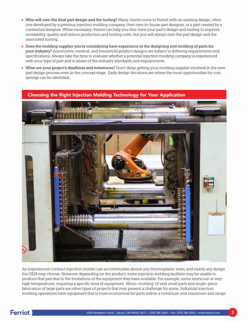
Choosing the Right Injection Molding Technology for Your Application
An experienced contract injection molder can accommodate almost any thermoplastic resin, and nearly any design the OEM may choose. However, depending on the product, some injection molding facilities may be unable to produce that part due to the limitations of the equipment they have available. For example, some resins run at very high temperatures, requiring a specific kind of equipment. ‘Micro-molding’ of very small parts and single-piece fabrication of large parts are other types of projects that may present a challenge for some. Industrial injection molding operations have equipment that is most economical for parts within a minimum and maximum size range.
41000 Arlington Circle | Akron, OH 44306-3973 | (330) 786-3000 | Fax: (330) 786-3001 | www.ferriot.com
Ferriot offers molding technologies to suit the requirements of a wide range of applications.
Ý Traditional injection molding: Traditional injection molding is typically done in two stages. In the injection stage, melted thermoplastic is injected into a mold; in the packing stage, pressure is applied and the plastic is formed into the shape of the mold. Ferriot’s injection molding press can produce parts weighing a few grams to those weighing 17 pounds, using presses with clamping force ranging from 40 to 1,600 tons. For simple or complex part geometries for both large and small applications, Ferriot can meet your part requirements.
Ý Structural foam injection molding: Structural foam-molded plastics can replace many types of materials, including metal, wood, concrete and fiberglass. In structural foam molding, the injection stage is basically the same as in traditional injection molding, but the packing stage is augmented by a chemical blowing agent mixed with the thermoplastic material to create thermoplastic foam. That chemical blowing agent is triggered by heat and expands the material by creating a microcellular structure to form the part against the mold. Parts made using structural foam molding generally weigh less and aren’t as dense as traditional injection molded parts. Actual weight savings can vary, but parts made using structural foam molding can be as much as 10–30 percent lighter than other parts, while retaining durability. Structural foam molding also scales well, so large or bulky parts can be manufactured while still retaining the superior production speed offered by injection molding. Structural foam parts can be painted or otherwise finished using the same methods used for other plastics. Finished part surfaces are smooth for easy cleaning. Structural foam molded parts also offer an excellent stiffness-to-weight ratio for added durability without added weight.
Ý Gas-assisted injection molding: This molding process involves injecting an inert gas into an injection molded part during the packing stage. The process employs compressed gas as the “packing medium,” providing dimensional stability for thick molded parts, and reducing warp and sink marks. This technique uses less injection pressure and can reduce clamp tonnage requirements, saving on the amount of energy and cost required to produce them.
Ý Overmolding: This is the process of combining two or more molded plastic or elastomer parts to make a single finished part. For example, Ferriot developed a softer, easier touch on an operating room light for better handling during surgery. For this project, the base layer part was molded, and then an additional softer plastic layer was molded over and around the original part.
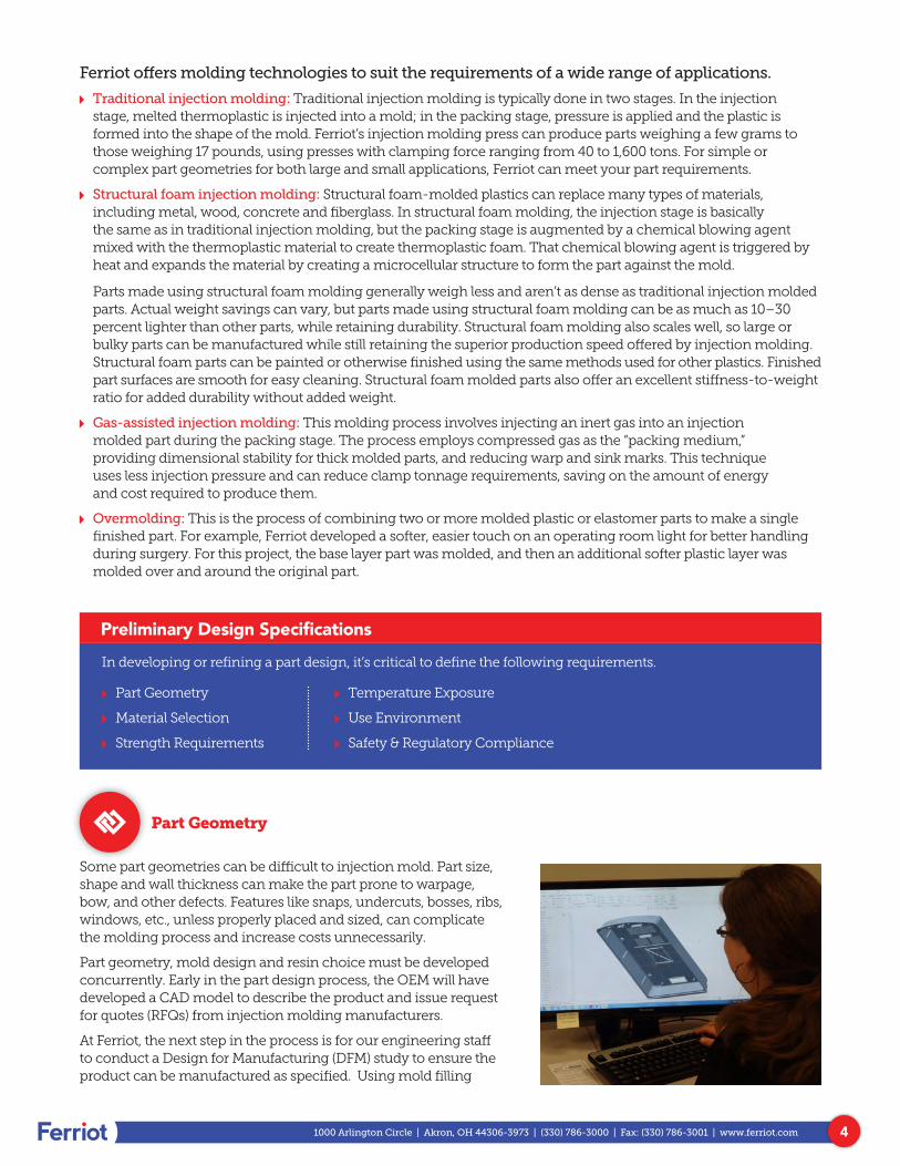
Part Geometry
Some part geometries can be difficult to injection mold. Part size, shape and wall thickness can make the part prone to warpage, bow, and other defects. Features like snaps, undercuts, bosses, ribs, windows, etc., unless properly placed and sized, can complicate the molding process and increase costs unnecessarily.
Part geometry, mold design and resin choice must be developed concurrently. Early in the part design process, the OEM will have developed a CAD model to describe the product and issue request for quotes (RFQs) from injection molding manufacturers.
At Ferriot, the next step in the process is for our engineering staff to conduct a Design for Manufacturing (DFM) study to ensure the product can be manufactured as specified. Using mold filling
Preliminary Design Specifications
In developing or refining a part design, it’s critical to define the following requirements.
Ý Part Geometry
Ý Material Selection
Ý Strength Requirements
Ý Temperature Exposure
Ý Use Environment
Ý Safety & Regulatory Compliance
51000 Arlington Circle | Akron, OH 44306-3973 | (330) 786-3000 | Fax: (330) 786-3001 | www.ferriot.com
analysis and experiential knowledge, our engineers will evaluate how the resin will flow into the proposed tool design, fill the cavity, pack, cool and eject. The DFM process ensures the product is can be created while still meeting the quality requirements as designed, thus avoiding costly downtime and tool revisions.
Some large OEMs have internal capability to use their CAD renderings and sophisticated software to run simulations on the design before it’s even an approved project! It’s very important to run these analyses, no matter who is performing them.
If the simulation reveals problems, our engineers alert the customer right away. Sometimes it’s as easy as sending a picture to the customer informing them of areas that won’t fill or pack during the process. Our engineers will propose changes to the tool or the product design to insure that it is manufacturable and repeatable.
Material Selection
Types of Resins Available
The first step in the resin selection process is to identify the key physical attributes that your end product requires:
Ferriot keeps more than 150 varieties of resin in stock and can draw on the resources of a global network of suppliers for fast access to other types.
Thermoplastic resins come in two basic classes: engineering grade resins and commodity resins. Each category includes a variety of resins which provides flexibility match a resin to a part based upon application, part design and moldability.
Engineering Grade Resins
Ý Nylon: Tough, superior thermal and chemical resistance, plus a wide variety of grades available with broad scope of physical properties.
Ý Polycarbonate: Strong, high flex modulus, good temperature range, transparent for lenses and multiple colors.
Ý ABS: Good impact strength, superior surface quality, good colorability, good rigidity, with electroplatable grades available.
Ý PC/ABS: Good processability, toughness at low temperature, superior dimensional stability.
Ý TPE: “Soft” touch, rubber replacement materials, good tear strength and good flexibility.
Ý Acrylic: Transparent, good for some outdoor applications.
Ý Acetal: Excellent wear resistance, great for gears and high wear applications.
Ý Structural Foam: Excellent material to be used in where metal replacement is considered. Good weight-to- stiffness ratio.
Commodities Grades
Ý Polypropylene: Versatile material, variety of grades in homopolymer and copolymer classes, good fatigue resistance, excellent chemical resistance, lower cost.
Ý Polyethylene: Very versatile, low-cost material, variety of grades in linear low-density polyethylene (LLDPE), low-density polyethylene (LDPE) and high-density polyethylene (HDPE), tough, weatherable, and easily processed.
Ý Polystyrene (PS): Available in general purpose and high impact (HIP) polystyrene, lower cost, range of impact from low to high, good clarity in general purpose (GPPS) grades, good rigidity.
Ý Polyvinyl chloride (PVC): Low cost, chemical resistant, can be colored, weatherable, and naturally flame retardant.
For additional guidance on the factors that go into choosing appropriate resins, download a free copy of our Injection Molding Resin Selection Workbook.
Ý Fatigue resistance
Ý Electrical properties
Ý Impact strength
Ý Flammability
Ý Chemical and environmental resistance
Ý Flexible strength
Ý Temperature operating range
61000 Arlington Circle | Akron, OH 44306-3973 | (330) 786-3000 | Fax: (330) 786-3001 | www.ferriot.com
Strength Requirements
Describe the level of strength the part requires. Some parts must be able to withstand repeated impact or force (such as a switch) while others need to support the weight of internal components. In some cases, it’s possible to add strength and durability through the use of structural reinforcements to the part such as ribs; in others, the choice of resin or the use of glass or carbon fiber reinforcement offer a better solution. In the early stages of the part development process, finite element analysis is crucial for understanding a part’s rigidity and performance in use or under load by simulating how a part will move or flex in response to loads, stresses and strains.
If it is a load-bearing part, describe the amount of weight or stress it must withstand, the duration for which the load will be applied, the size of the bearing area, specifications for tensile strength (the greatest longitudinal stress a substance can bear without tearing apart), and any required safety factor.
Creep is the tendency of solid materials, including thermoplastic resins, to move slowly or deform permanently as the result of long-term mechanical stress. The rate of deformation depends on the properties of the material used, exposure time and temperature, and the applied structural load.
Required Rigidity
Ý Tensile modulus: A measure of stiffness of a material, which can be used to predict the elongation or compression of an object as long as the stress is less than the yield strength of the material.
Ý Flexural modulus: A measure of stiffness of a material, which will affect the degree to which a structural element is displaced in use or under load.
Required Impact Resistance
Ý Type of expected impact load (e.g., fall onto a hard surface from 5 feet, having loads dropped on it, etc.). “Upfront” impact testing offers valuable insights. By using molds that are similar to the final part, one can produce prototype parts using an array of resins, and then compare their impact resistance.
Ý Notched Izod test performance (per ASTM D256. Results are expressed in energy lost per unit of thickness at the notch).
Ý Why is impact resistance important for this application?
Temperature Exposure
Ý Minimum/maximum temperatures the part must withstand.
Ý Type of heat source (flame, sun exposure, heating element, etc.).
Ý Heat deflection temperature (HDT) is the temperature at which a polymer or plastic sample deforms under a specified load. How high a temperature must the part withstand without deformation?
Ý Interference with other materials? (Dissimilar materials have considerable thermal expansions or contractions and may cause an interference condition.)
71000 Arlington Circle | Akron, OH 44306-3973 | (330) 786-3000 | Fax: (330) 786-3001 | www.ferriot.com
Indoor Use
Ý Bacteria resistance
Ý Flame resistance
Ý Cleaning/chemical agent resistance
Ý PVC plasticizers
Ý Glue/adhesives chemical resistance
Ý Sterilization process resistance
Outdoor Use/Weathering
Ý Property/color retention on UV/light/thermal exposure
Ý Moisture resistance
Ý Long-term aging (due to both heat and moisture)
Electrical Performance
Ý Type of power supply
Ý Voltage
Ý Frequency
Ý Specification for dielectric constant
Ý Exposure to static electricity
Chemical Exposure
Ý Chemical type
Ý Exposure type (i.e., spray, immersion, wipe)
Ý Duration of exposure
Ý Exposure to the chemical at elevated temperatures
Fastening/Assembly Methods to Be Used
Ý Screws, adhesives, ultrasonic bonding, etc.?
Use Environment
Identify any factors that may have an impact on part appearance or performance.
Color
Ý Color palette requirements (i.e., does it need to match a corporate color standard or the color used in other products?)
Ý Color consistency across part
Ý Part to part color consistency
Ý Color tolerances
Ý Cost of color
Ý Color stability during molding
Ý Natural color consistency
Ý Color space limitations of the resin
Ý Color stability (initial and long term)
Ý Depth of color
Gloss, Texture and Depth
Ý Gloss requirement (initial and long term)
Ý Gloss consistency
Ý Haze
Ý Opacity
Ý Surface texture
Ý Surface smoothness
Ý Transparency
Ý Pit/mold texture replication
Appearance
Ý Will this be an exposed/visible part?
Ý Any coatings required (i.e., paint, silicone hard coat, film pad printing, etc.).
Ý Identify critical aesthetic considerations.
81000 Arlington Circle | Akron, OH 44306-3973 | (330) 786-3000 | Fax: (330) 786-3001 | www.ferriot.com
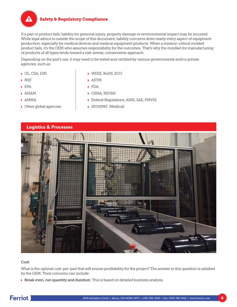
Safety & Regulatory Compliance
If a part or product fails, liability for personal injury, property damage or environmental impact may be incurred. While legal advice is outside the scope of this document, liability concerns drive nearly every aspect of equipment production, especially for medical devices and medical equipment products. When a mission-critical molded product fails, it’s the OEM who assumes responsibility for the outcomes. That’s why the mindset for manufacturing of products of all types tends toward a risk-averse, conservative approach.
Depending on the part’s use, it may need to be tested and certified by various governmental and/or private agencies, such as:
Logistics & Processes
Cost
What is the optimal cost-per-part that will ensure profitability for the project? The answer to this question is satisfied by the OEM. Their concerns can include:
Ý Break even, run quantity and duration: This is based on detailed business analysis.
Ý UL, CSA, DIN
Ý NSF
Ý EPA
Ý AHAM
Ý AMMA
Ý Other global agencies
Ý WEEE, RoHS, ECO
Ý ASTM
Ý FDA
Ý OSHA, NIOSH
Ý Federal Regulations, ANSI, SAE, FMVSS
Ý ISO10993 (Medical)
91000 Arlington Circle | Akron, OH 44306-3973 | (330) 786-3000 | Fax: (330) 786-3001 | www.ferriot.com
Ý Production planning: Project planning for the immediate future as well as longer term manufacture. Does the volume of production justify the cost of having more than one tool created at the same time? What class of mold is required based upon production volumes? The expected life of the mold is based upon number of cycles, mold material and hardness.
Ý Optimization: Shipping, secondary operations, and efficiencies are identified, as well as the business decisions that weigh per piece costs against long-term profitability.
Ferriot provides pricing for the injection tool, molded part and secondary operations, but it’s up to the OEM to decide what fits their budget constraints. For most OEMs, a request for a quote from an injection molder like Ferriot means that the preliminary budget analysis justifies going forward; they are ready to proceed.
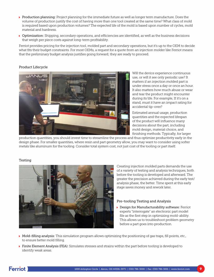
Product Lifecycle
Will the device experience continuous use, or will it see only periodic use? It matters if an injection molded part is under stress once a day or once an hour. It also matters how much abuse or wear and tear the product might encounter during its life. For example, If it’s on a stand, must it have an impact rating for accidental tip-over?
Estimated annual usage, production quantities and the expected lifespan of the product will influence many decisions about the part, including mold design, material choice, and finishing methods. Typically, for larger
production quantities, you should invest time to streamline the process and thus optimize productivity early in the design phase. For smaller quantities, where resin and part geometry allow, you may want to consider using softer metals like aluminum for the tooling. Consider total system cost, not just cost of the tooling or part itself.
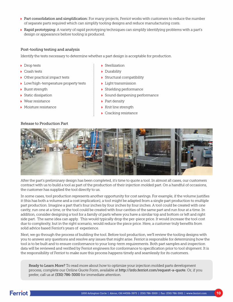
Testing
Creating injection molded parts demands the use of a variety of testing and analysis techniques, both before the tooling is developed and afterward. The greater the precision achieved during the early test/analysis phase, the better. Time spent at this early stage saves money and rework later.
Pre-tooling Testing and Analysis
Ý Design for Manufacturability software: Ferriot experts “interrogate” an electronic part model file as the first step in optimizing mold-ability. This allows us to troubleshoot problem geometry before a part goes into production.
Ý Mold-filling analysis: This simulation program allows optimizing the positioning of gas traps, fill points, etc., to ensure better mold filling.
Ý Finite Element Analysis (FEA): Simulates stresses and strains within the part before tooling is developed to identify weak areas.
101000 Arlington Circle | Akron, OH 44306-3973 | (330) 786-3000 | Fax: (330) 786-3001 | www.ferriot.com
Ý Part consolidation and simplification: For many projects, Ferriot works with customers to reduce the number of separate parts required which can simplify tooling designs and reduce manufacturing costs.
Ý Rapid prototyping: A variety of rapid prototyping techniques can simplify identifying problems with a part’s design or appearance before tooling is produced.
Post-tooling testing and analysis
Identify the tests necessary to determine whether a part design is acceptable for production.
Ý Drop tests
Ý Crash tests
Ý Other practical impact tests
Ý Low/high-temperature property tests
Ý Burst strength
Ý Static dissipation
Ý Wear resistance
Ý Moisture resistance
Ý Sterilization
Ý Durability
Ý Structural compatibility
Ý Light transmission
Ý Shielding performance
Ý Sound dampening performance
Ý Part density
Ý Knit line strength
Ý Cracking resistance
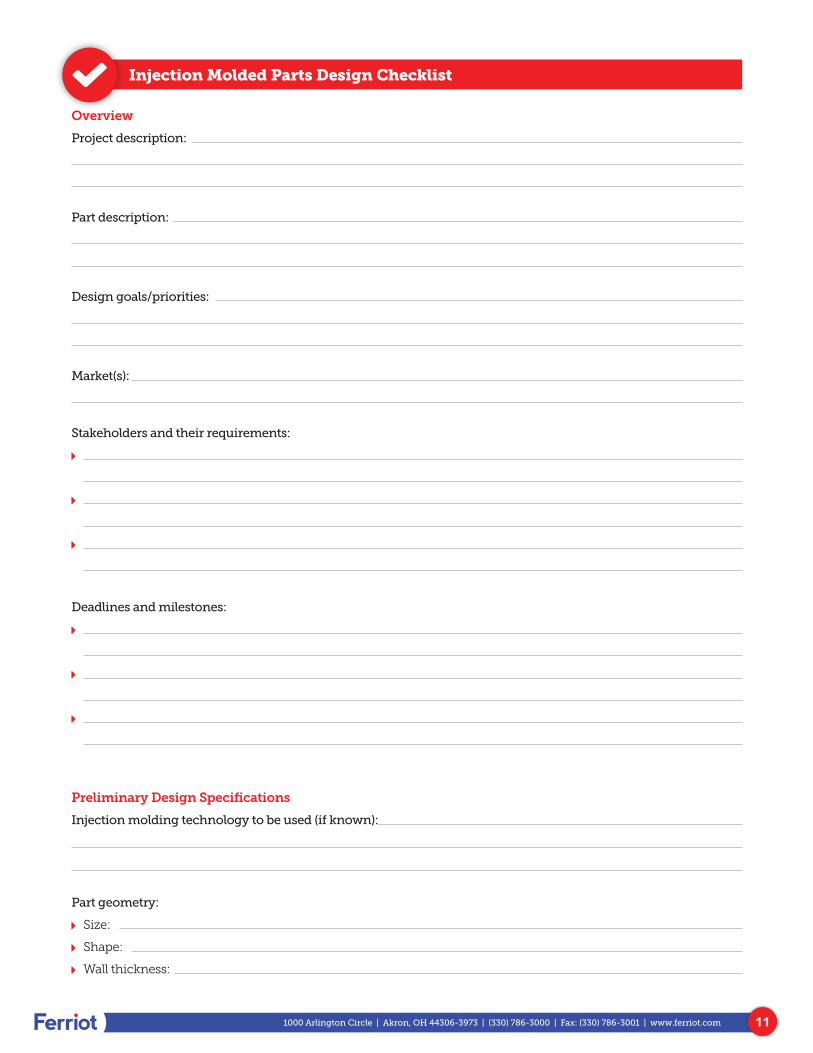
Release to Production Part
After the part’s preliminary design has been completed, it’s time to quote a tool. In almost all cases, our customers contract with us to build a tool as part of the production of their injection molded part. On a handful of occasions, the customer has supplied the tool directly to us.
In some cases, tool production represents another opportunity for cost savings. For example, if the volume justifies it (this has both a volume and a cost implication), a tool might be adapted from a single part production to multiple part production. Imagine a part that’s four inches by four inches by four inches. A tool could be created with one cavity, run one at a time, or the tool could be created with four cavities of the same part and run four at a time. In addition, consider designing a tool for a family of parts where you have a similar top and bottom or left and right side part. The same idea can apply. This would typically drop the per-piece price. It would increase the tool cost due to complexity, but in the right scenario, would reduce the piece price. Here, a customer truly benefits from solid advice based Ferriot’s years of experience.
Next, we go through the process of building the tool. Before tool production, we’ll review the tooling designs with you to answer any questions and resolve any issues that might arise. Ferriot is responsible for determining how the tool is to be built and to ensure conformance to your long-term requirements. Both part samples and inspection data will be reviewed and verified by Ferriot engineers for conformance to specification prior to tool shipment. It is the responsibility of Ferriot to make sure this process happens timely and seamlessly for its customers.
Ready to Learn More? To read more about how to optimize your injection molded parts development process, complete our Online Quote Form, available at http://info.ferriot.com/request-a-quote. Or, if you prefer, call us at (330) 786-3000 for immediate attention.
111000 Arlington Circle | Akron, OH 44306-3973 | (330) 786-3000 | Fax: (330) 786-3001 | www.ferriot.com
Injection Molded Parts Design Checklist
Overview
Project description:
Part description:
Design goals/priorities:
Market(s):
Stakeholders and their requirements:
Ý
Ý
Ý
Deadlines and milestones:
Ý
Ý
Ý
Preliminary Design Specifications
Injection molding technology to be used (if known):
Part geometry:
Ý Size:
Ý Shape:
Ý Wall thickness:
121000 Arlington Circle | Akron, OH 44306-3973 | (330) 786-3000 | Fax: (330) 786-3001 | www.ferriot.com
Main selection specifications/Key physical part attributes:
Ý Chemical exposure:
Ý Electrical properties:
Ý Environment:
Ý Fatigue resistance:
Ý Flammability:
Ý Strength requirements:
Ý Temperature exposure/operating range:
Ý Safety & regulatory compliance/certifications and required testing:
Ý Appearance (Identify critical aesthetic considerations):
Ý Fastening/assembly methods to be used:
Cost Considerations:
Ý Optimal cost per part:
Ý Estimated annual usage:
Ý Estimated quantities:
Ý Expected lifespan:
Notes


![AUTOMOTIVE COMPOSITES CONSORTIUM B-PILLAR MOLDING … › SPEA_CD › SPEA2005 › pdf › l › l3.pdf · 2009-06-08 · molded by structural reaction injection molding (SRIM) [3]](https://img.pdfslide.net/doc/110x75/5f0cbf787e708231d436ef93/automotive-composites-consortium-b-pillar-molding-a-speacd-a-spea2005-a-pdf.jpg)