Embed Size (px)
Citation preview
2nd International Conference and workshop on Emerging Trends in Technology (ICWET) 2011
Proceedings published by International Journal of Computer Applications® (IJCA)
26
Designing Optimized Cassegrain with Balanced Feed
Krunal Patel Department of Electronics & Telecommunication
VESIT, Mumbai, India.
ABSTRACT
Cassegrain Reflector Antenna Design consists of various effects
caused by blockage and its effect on overall performance. The
design for minimum blockage condition results in geometry that
offers lower amount of blockage and increased spillover past the
subreflector. To avoid this, optimized design of the antenna
results in geometry that offers lower amount of spillover past the
edges of the main reflector and increases some percentage of
blockage. The design of feed elements for Cassegrain antennas
is considered in the following section. It includes the design of
conical corrugated horn antenna having throat section. Throat
section is used for the purpose of achieving match between input
waveguide and horn thereby maintaining low VSWR. The
Scalar Horns are used to obtain identical performance in both
the principal planes. The dual reflector design is simulated on
the ‘Induced Current Analysis of Reflector Antenna’ software.
Ansoft HFSS is used to obtain the radiation characteristics of the
Corrugated Horn.
General Terms
Cassegrain dual reflector design, Feed design for Cassegrains,
Design approaches
Keywords
Conical Corrugated horn, Scalar horn, Sidelobe reduction,
Cross-polarization reduction
1. INTRODUCTION The endeavours of synthesizing, analyzing and designing
reflector antennas of different configurations did not really
emerge until a number of radar applications evolved to satisfy
growing technical demands. A large number of demands of
reflectors for satellite communications and tracking, microwave
communications, radar applications and point-to-point
communications have resulted in the development of both the
complicated reflector configurations and analytical and practical
design techniques. To meet the specifications like off-axis beam,
contour beams, multiple beams, different new configurations of
reflector antennas are investigated. Many radio frequency
communication antennas use only one polarization and
reasonable specification for isolation between orthogonal
polarization and the desired polarization is specified.
Nevertheless to use the available frequency spectrum
effectively, the antennas are designed for operating with dual
polarizations at the same operating frequency. They require
tighter constraints on cross-polarization performance and
isolation between two operating polarizations. For producing a
pencil beam with significantly low side lobe levels, the
paraboloid[7] is the most suitable type when used with a feed
element that can produce the desired pattern on the reflector. For
applications in terrestrial communication systems, front-fed
geometry offers ease of construction. Cassegrainian systems[1]
may succeed over the front–fed configuration at the cost of
economy. Considerable improvement in efficiency can be
achieved by shaping of reflector profiles. Most of the earth-
station antennas use these techniques.
The feed elements used may be pure mode circular waveguides
and conical horns, rectangular horn antennas, hybrid mode
corrugated waveguides and conical corrugated horns depending
upon the requirement. Since metallic surface having
corrugations is the most suitable type of the surface for meeting
the anisotropic conditions, hybrid mode waveguides or horns are
widely used as feed elements. Large reflector antennas designed
for operating with different frequency bands employ cluster of
feeds that may include simple hybrid mode horn antennas as
well as lens corrected horn antennas designed for various
frequency bands. It can also be considered as an example of
movable feed elements.
2. DESIGN APPROACHES
2.1 The Minimum Blockage Condition The minimum blockage condition[1] offers smaller size of the
subreflector and reduced amount of sidelobes. If the overall diameter of the feed is Df, the condition for minimum blockage
𝐹
2𝑓=
𝑑
𝐷𝑓 (2.1)
As mentioned earlier the diameter for minimum blocking
condition is given by,
𝐷𝑏𝑚𝑖𝑛
= 2
𝑘𝐹𝜆 (2.2)
It shows that the shadows created by feed aperture and the
hyperboloid are nearly equal and they contribute to the aperture
blockage. If the distance of the subreflector from feed is
reduced(i.e. Ls in the figure), the blocking offered by feed would
be greater. If the phase centre of the feed is known then it should
be coincided with the real focal point and the Minimum
Blockage Condition becomes,
𝐹
2𝑓 − 𝐷𝑝𝑐
=𝑑
𝐷𝑓 2.3
The blockage loss for d/D < 0.1 or 1% area blockage is less than
0.1 dB, but increases rapidly above 1% blockage.
If the focal length of the paraboloid is an integral number of half
wavelengths i.e. F = mλ/2, the back lobe of the primary pattern
is 180 deg. out of phase with the main lobe. If the focal length is
adjusted F = (2m +1)λ/4 (where m is an integer), the back lobe
and the main lobe of the primary radiation are in phase and the
2nd International Conference and workshop on Emerging Trends in Technology (ICWET) 2011
Proceedings published by International Journal of Computer Applications® (IJCA)
27
back lobe adds to the gain. If these requirements are not satisfied
exactly, the feed should be located at the point, nearer to the
focus, at which the value of F satisfies the above mentioned
criteria. Deviations from the constant phase of the aperture
should be kept within λ/8 and certainly should not exceed λ/4.
Two factors contribute to the phase error.
Distortion of paraboloid surface.
Deviation of the primary wavefronts from spherical waves.
The first criterion is identical to surface irregularities and it can
be considered as a tolerance that is acceptable in constructing
the reflector. The latter criterion defines the feed as a point
source cone. The angular aperture of the main reflector should
be included within the point source cone. Addition of
hyperboloid shifts the phase center of a spherical wave from the
real focal point to the virtual focal point. It reduces the edge
taper on the subreflector and also reduces the taper of the
diffracted beam. Hence, for the given subreflector size, if the
focal length to diameter ratio (i.e. F/D ratio) is increased, the
illumination taper is reduced, spillover at the main reflector and
the subreflector is increased and the subreflector blockage is
reduced. The blockage effects are negligible for smaller
subreflector size. The antenna efficiency is affected by the
illumination efficiency and the spillover. Clearly, if the
illumination efficiency is increased, the spillover efficiency
reduces.
2.2 Design Tips Focal length to diameter ratio is taken in the range 0.25 and
0.55.
To reduce the diffraction losses, subreflector diameter
should be >> 5λ.
It should be kept less than 10% of main reflector diameter
for >> 99% blockage efficiency and lower secondary
radiation.
The distance of the subreflector from the feed is selected on
the basis of feed pattern. Efforts should be carried out to
reduce the feed aperture phase error.
The feed may be located behind the main reflector (i.e. for
negative value of Lm) if the feed support is creating
mechanical problems. The feed location is affected by the
dimensions of the feed support cone, inclusion of
polarization diplexers, lateral dimensions of the feed and
the space available behind the paraboloid.
The included angle of the subreflector should be selected in
a way that minimizes the spillover. Usually, -10 dB to -15
dB edge taper is adjusted on the subreflector.
2.3 The Optimized Design of the
Cassegrainian System Even though the Optimized Design of the Cassegrainian System
allows some percentage of blockage thereby increasing the size
of the subreflector, it offers reduced amount of spillover past the
edges of the main reflector. Hence it is preferred in most of the
cases.
Including the effect of center blockage, subreflector diffraction
and blockage from subreflector, the following equations can be
written[4][6].
The relation between blockage parameter and diffraction parameter is given by
𝐶𝑑
= 1
𝜋
[cos(𝜓2)]2
sin 𝜃0 𝐶𝑏 2.4
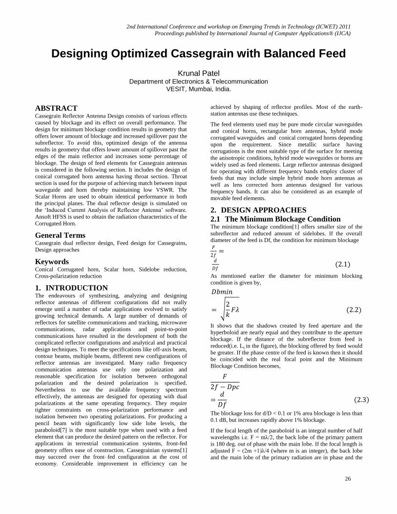
Figure 1. Classical Cassegrain Geometry
For most of the antennas the subtended angle by the main
paraboloid reflector is close to 90 deg. and that by the subreflector is small.
𝐶𝑑
≈ 𝐶𝑏
𝜋 2.5
The overall aperture efficiency is defined as the product of the following terms[6],
𝜂𝑎 = 𝜂𝑓𝜂𝑖 2.6 The feed efficiency is given by,
𝜂𝑓
= 2 1 − 𝐴0
2
− ln 𝐴0 2.7
It indicates that feed efficiency is mainly dependent on the illumination taper. The overall interference is indicated by ηi.
The blockage parameter is given by,
𝐶𝑏 = − ln 𝐴0
[1 − 𝐴0]= 𝜋𝐶𝑑 (2.8)
It is desired to maximize the aperture efficiency w.r.t. d. Hence the resultant d/D ratio is given by the following equation.
𝑑
𝐷
= 1
(4𝜋)2
[cos(𝜓2)]4
sin𝜃0𝐴0
2 𝜆
𝐷
1/5
(2.9)
From the above equation, it is clear that d/D ratio is more
dependent on the edge taper on the subreflector. So, in addition
to cosnψ, other distributions (e.g. Gaussian) can also be
launched.
From the geometry of the figure, following equations can be written.
2nd International Conference and workshop on Emerging Trends in Technology (ICWET) 2011
Proceedings published by International Journal of Computer Applications® (IJCA)
28
tan 𝜃0
2
= ±1
4
𝐷
𝐹 (2.10)
The positive sign in the above formula applies to the Cassegrain forms, and the negative signs to Gregorian forms.
1
tan(𝜃0)+
1
tan(𝜓)
= 2𝐹𝑐
𝑑 (2.11)
1 − sin
12 (𝜃0 − 𝜓)
sin12
(𝜃0 + 𝜓)
= 2𝐿𝑣
𝐹𝑐 (2.12)
The parameters D, F, Fc and ψ may be determined by
considerations of antenna performance and space limitation; θ0,
Ds and Lv would then be calculated from the above formulae. ψ may be determined independently of the shape factor.
The contour of the main dish is given by the equation,
𝑥𝑚 =𝑦𝑚
2
4𝐹 (2.13)
The contour of the subdish is given by,
𝑥𝑠
= 𝑎 1 + (𝑦𝑠𝑏
)2
− 1 (2.14)
where
𝑒
= sin
12
(𝜃0 + 𝜓)
sin12 (𝜃0 − 𝜓)
(2.15)
𝑎 = 𝐹𝑐
2𝑒 (2.16)
𝑏
= 𝑎 𝑒2 − 1 (2.17)
The parameters e, a and b are the parameters of the hyperbola, a
is the half traverse axis, and b is half the conjugate axis.
The magnification M is given by,
𝑀 =𝐹𝑒𝐹
=𝑒 + 1
𝑒 − 1 (2.18)
For the analysis of the radiation pattern of reflector antennas, the
widely used techniques are PO (Physical Optics) and PTD.
Also, to obtain the wide angle secondary radiation
characteristics, the GTD (Geometrical Theory of Diffraction) is
considered as a versatile tool. Since the reflectors have larger
aperture dimensions, MoM and FEM methods are not economic.
Restriction on the wave order can be determined with the help of
powerful spherical wave theory. It involves the use of elemental
wave functions and determination of spherical wave suit to the
desired illumination.
The Classical Cassegrainian System for satisfying the following
performance parameters of a radar antenna is considered next.
2.3.1 Design Specifications Following performance specifications are taken into account to
design Classical Cassegrain Antenna. The antenna is to be designed for cloud radar operating at 34.86 GHz.
Frequency 34.86 GHz
Gain > 54 dB
Half Power Beamwidth 0.3 deg. x 0.3 deg.
Side-lobe level Less than 26 dB
Intrinsic Cross-polarization Minimum
Maximum Unambiguous Range 15 km
Polarization In both the planes
2.3.2 The Optimized Design for Specified
Parameters Following design procedure yields optimized design of
Cassegrain antenna. It takes care of reduction in aperture
efficiency caused by the scatter from the subreflector.
Since side-lobe requirement is < -26 dB, 12 dB Edge Taper (ET)
on Subreflector is required. (Since subtended angle by
hyperboloid is within 30 deg. in most of the applications, Space
Attenuation is usually neglected i.e. ET ≈ FT, where FT stands
for Feed Taper.)
Taper in dB = −20𝑙𝑜𝑔𝐴0
−0.6 = 𝑙𝑜𝑔10𝐴0
𝐴0 = 0.25
The blockage parameter is given by (2.8),
𝐶𝑏 = 1.85
The diffraction parameter is given by (2.5),
𝐶𝑑 = 𝐶𝑏
𝜋= 0.59
Taking the main reflector diameter
D = 200λ
For focal length to diameter ratio F/D =0.3
Fm = 1.72 * 0.3 = 0.516 m = 516 mm
tan 𝜃0
2 = ±
1
4
𝐷
𝐹= 0.83
𝜃0 = 39.810 × 2 = 79.610
For Fe/D ratio of, Fe/D = 1.5
Magnification is given by,
𝑀 =𝐹𝑒
𝐹=
1.5𝐷
0.3𝐷= 5 𝑀 =
𝐹𝑒
𝐹=
1.5𝐷
0.3𝐷= 5
2𝑒
2=
𝑀 + 1
𝑀 − 1
Therefore,
e = 3/2 = 1.5
Alternatively, from (2.15)
2nd International Conference and workshop on Emerging Trends in Technology (ICWET) 2011
Proceedings published by International Journal of Computer Applications® (IJCA)
29
𝑒 =sin
12
(79.61 + 18.96)
sin12
(79.61 − 18.96)= 1.5
𝑎 = 𝐹𝑐
2𝑒=
0.1854
2 × 1.5= 0.0618 𝑚
𝑏 = 0.0618 𝑒2 − 1 = 0.0618 1.5 2 − 1= 0.069 𝑚
tan 𝜓 =1
2𝐹𝑐𝑑
−1
tan 𝜃0
2𝐹𝑐𝑑
= 1
tan 18.96+
1
tan 79.61= 3.09
Therefore
𝐹𝑐𝑑
= 1.545
The depth of the main reflector is given by,
𝑑𝑒𝑝𝑡 = 𝐷2
16𝐹= 0.3583 𝑚 = 358.3 𝑚𝑚
The subreflector diameter can be found as [from (2.9)] ,
𝑑
𝐷=
1
(4𝜋)2
[cos(9.48)]4
sin 79.61(0.25)2
1
200
1/5
= 0.07
Now, D = 200λ gives d = 0.12 m.
Feed Efficiency, as mentioned earlier in (2.7)
𝜂𝑓 = 2[1 − 0.25]2
−ln(0.25)= 0.81
The overall interference (including center blockage, spillover and neglecting strut blockage)
(𝜂𝑖)𝑚𝑎𝑥 ≈ 1 − 𝐶𝑏 1 + 4 1 − 𝑑
𝐷
𝑑
𝐷
2
2
= 0.92
Aperture efficiency is given by,
𝜂𝑎 = 𝜂𝑓 × 𝜂𝐼 = 0.81 × 0.92 = 0.7452
Gain of the Cassegrainian system is given by,
𝐺 = ∈𝑎𝑝 𝜋2(𝐷 − 𝑑)2
𝜆2
= 0.7452 × (𝜋)2 ×(200𝜆 − 14𝜆)2
𝜆2
= 252672.14
G = 2.52 * (10)5 =54.03 dB
The distance of subreflector from the main reflector focal point can be found as
1 − sin
12 79.61 − 18.96
sin12 79.61 + 18.96
=2𝐿𝑣
0.1854
𝐿𝑣 = 0.335 × 0.1854
2= 0.031 𝑚 = 31 𝑚𝑚
Hence, the subreflector should be located 31 mm away from the
focal point of the main reflector. The half-angle subtended by
the subreflector is found as 18.96 degree. Conical Corrugated
horn having aperture diameter 4.09λ i.e. aperture diameter of
0.035174 m (35.174 mm) and 150 flare angle is used as the feed
element. Detailed design of conical corrugated horn is described
in the next section.
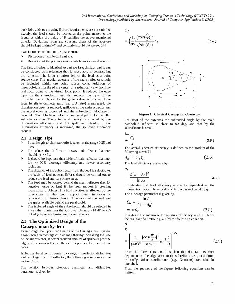
The far-field radiation pattern is obtained using ‘Induced
Current Analysis of Reflector Antenna Software’ that works on
PO and PO/PTD principles.
Figure 2. Cassegrain Antenna Geometry (Solid Metallic
Surface)
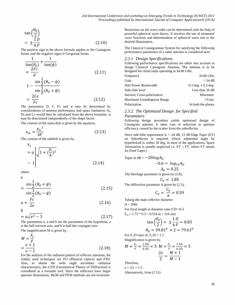
Figure 3. Far Field Phi Constant Cuts (Co-polar Magnitude)
2nd International Conference and workshop on Emerging Trends in Technology (ICWET) 2011
Proceedings published by International Journal of Computer Applications® (IJCA)
30
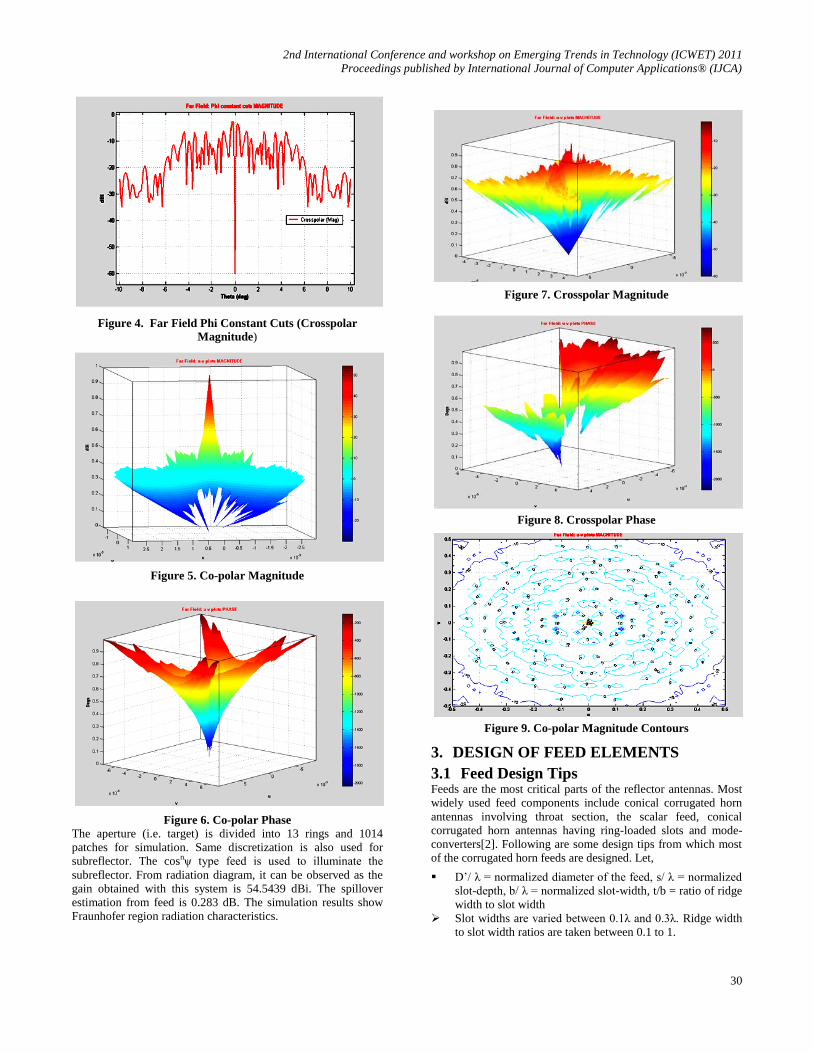
Figure 4. Far Field Phi Constant Cuts (Crosspolar
Magnitude)
Figure 5. Co-polar Magnitude
Figure 6. Co-polar Phase
The aperture (i.e. target) is divided into 13 rings and 1014
patches for simulation. Same discretization is also used for
subreflector. The cosnψ type feed is used to illuminate the
subreflector. From radiation diagram, it can be observed as the
gain obtained with this system is 54.5439 dBi. The spillover
estimation from feed is 0.283 dB. The simulation results show
Fraunhofer region radiation characteristics.
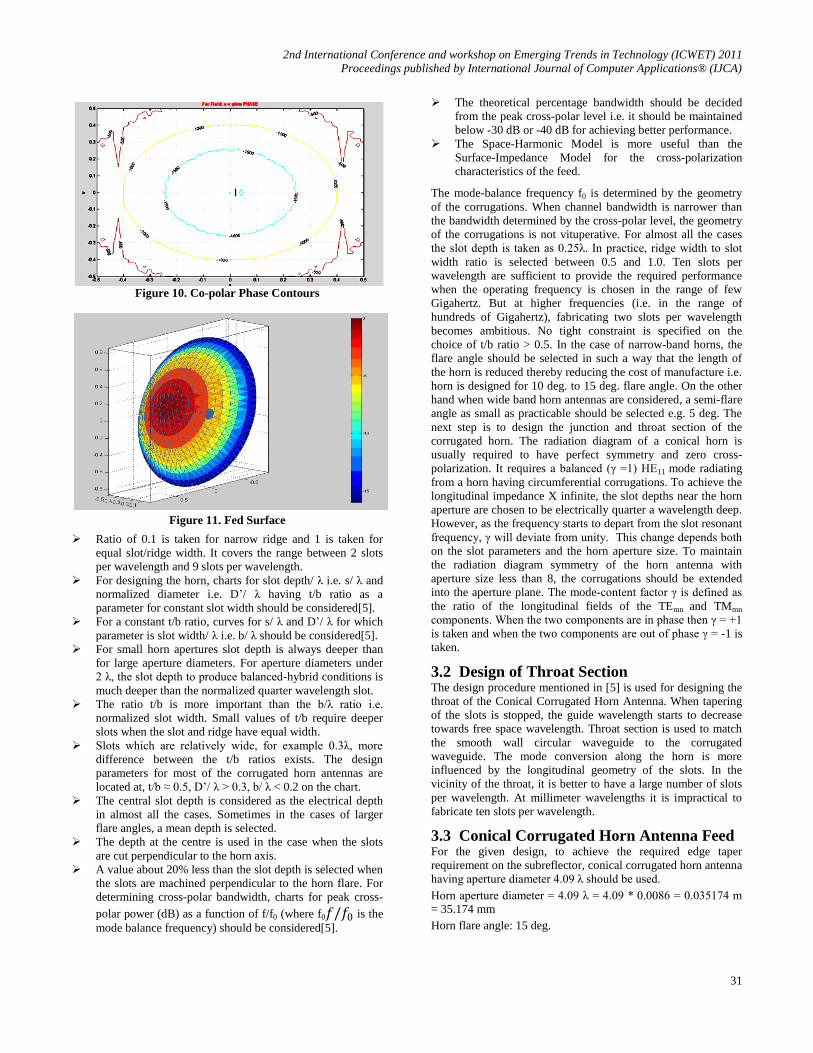
Figure 7. Crosspolar Magnitude
Figure 8. Crosspolar Phase
Figure 9. Co-polar Magnitude Contours
3. DESIGN OF FEED ELEMENTS
3.1 Feed Design Tips Feeds are the most critical parts of the reflector antennas. Most
widely used feed components include conical corrugated horn
antennas involving throat section, the scalar feed, conical
corrugated horn antennas having ring-loaded slots and mode-
converters[2]. Following are some design tips from which most
of the corrugated horn feeds are designed. Let,
D’/ λ = normalized diameter of the feed, s/ λ = normalized
slot-depth, b/ λ = normalized slot-width, t/b = ratio of ridge
width to slot width
Slot widths are varied between 0.1λ and 0.3λ. Ridge width
to slot width ratios are taken between 0.1 to 1.
2nd International Conference and workshop on Emerging Trends in Technology (ICWET) 2011
Proceedings published by International Journal of Computer Applications® (IJCA)
31
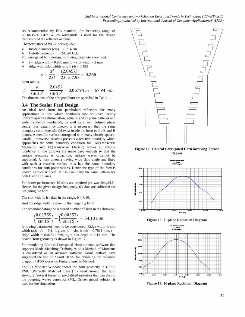
Figure 10. Co-polar Phase Contours
Figure 11. Fed Surface
Ratio of 0.1 is taken for narrow ridge and 1 is taken for
equal slot/ridge width. It covers the range between 2 slots
per wavelength and 9 slots per wavelength.
For designing the horn, charts for slot depth/ λ i.e. s/ λ and
normalized diameter i.e. D’/ λ having t/b ratio as a
parameter for constant slot width should be considered[5].
For a constant t/b ratio, curves for s/ λ and D’/ λ for which
parameter is slot width/ λ i.e. b/ λ should be considered[5].
For small horn apertures slot depth is always deeper than
for large aperture diameters. For aperture diameters under
2 λ, the slot depth to produce balanced-hybrid conditions is
much deeper than the normalized quarter wavelength slot.
The ratio t/b is more important than the b/λ ratio i.e.
normalized slot width. Small values of t/b require deeper
slots when the slot and ridge have equal width.
Slots which are relatively wide, for example 0.3λ, more
difference between the t/b ratios exists. The design
parameters for most of the corrugated horn antennas are
located at, t/b ≈ 0.5, D’/ λ > 0.3, b/ λ < 0.2 on the chart.
The central slot depth is considered as the electrical depth
in almost all the cases. Sometimes in the cases of larger
flare angles, a mean depth is selected.
The depth at the centre is used in the case when the slots
are cut perpendicular to the horn axis.
A value about 20% less than the slot depth is selected when
the slots are machined perpendicular to the horn flare. For
determining cross-polar bandwidth, charts for peak cross-
polar power (dB) as a function of f/f0 (where f0𝑓/𝑓0 is the
mode balance frequency) should be considered[5].
The theoretical percentage bandwidth should be decided
from the peak cross-polar level i.e. it should be maintained
below -30 dB or -40 dB for achieving better performance.
The Space-Harmonic Model is more useful than the
Surface-Impedance Model for the cross-polarization
characteristics of the feed.
The mode-balance frequency f0 is determined by the geometry
of the corrugations. When channel bandwidth is narrower than
the bandwidth determined by the cross-polar level, the geometry
of the corrugations is not vituperative. For almost all the cases
the slot depth is taken as 0.25λ. In practice, ridge width to slot
width ratio is selected between 0.5 and 1.0. Ten slots per
wavelength are sufficient to provide the required performance
when the operating frequency is chosen in the range of few
Gigahertz. But at higher frequencies (i.e. in the range of
hundreds of Gigahertz), fabricating two slots per wavelength
becomes ambitious. No tight constraint is specified on the
choice of t/b ratio > 0.5. In the case of narrow-band horns, the
flare angle should be selected in such a way that the length of
the horn is reduced thereby reducing the cost of manufacture i.e.
horn is designed for 10 deg. to 15 deg. flare angle. On the other
hand when wide band horn antennas are considered, a semi-flare
angle as small as practicable should be selected e.g. 5 deg. The
next step is to design the junction and throat section of the
corrugated horn. The radiation diagram of a conical horn is
usually required to have perfect symmetry and zero cross-
polarization. It requires a balanced (γ =1) HE11 mode radiating
from a horn having circumferential corrugations. To achieve the
longitudinal impedance X infinite, the slot depths near the horn
aperture are chosen to be electrically quarter a wavelength deep.
However, as the frequency starts to depart from the slot resonant
frequency, γ will deviate from unity. This change depends both
on the slot parameters and the horn aperture size. To maintain
the radiation diagram symmetry of the horn antenna with
aperture size less than 8, the corrugations should be extended
into the aperture plane. The mode-content factor γ is defined as
the ratio of the longitudinal fields of the TEmn and TMmn
components. When the two components are in phase then γ = +1
is taken and when the two components are out of phase γ = -1 is
taken.
3.2 Design of Throat Section The design procedure mentioned in [5] is used for designing the
throat of the Conical Corrugated Horn Antenna. When tapering
of the slots is stopped, the guide wavelength starts to decrease
towards free space wavelength. Throat section is used to match
the smooth wall circular waveguide to the corrugated
waveguide. The mode conversion along the horn is more
influenced by the longitudinal geometry of the slots. In the
vicinity of the throat, it is better to have a large number of slots
per wavelength. At millimeter wavelengths it is impractical to
fabricate ten slots per wavelength.
3.3 Conical Corrugated Horn Antenna Feed For the given design, to achieve the required edge taper
requirement on the subreflector, conical corrugated horn antenna
having aperture diameter 4.09 λ should be used.
Horn aperture diameter = 4.09 λ = 4.09 * 0.0086 = 0.035174 m = 35.174 mm
Horn flare angle: 15 deg.
2nd International Conference and workshop on Emerging Trends in Technology (ICWET) 2011
Proceedings published by International Journal of Computer Applications® (IJCA)
32
As recommended by EIA standard, for frequency range of
28.30-38.80 GHz WC28 waveguide is used for the design frequency of the reflector antenna.
Characteristics of WC28 waveguide:
Inside diameter (cm) : 0.714 cm
Cutoff-frequency : 24.620 GHz For corrugated horn design, following parameters are used.
t = ridge width = 0.906 mm, b = slot width = 2 mm
ridge width/slot width ratio = t/b = 0.453
𝑠 =𝑎2
2𝜆𝑙=
(2.045𝜆)2
2𝜆 × 7.9𝜆= 0.265
Slant radius,
𝑙 =𝑎
sin 150=
2.045𝜆
sin 150= 0.06794 𝑚 = 67.94 𝑚𝑚
The dimensions of the designed horn are specified in Table 1.
3.4 The Scalar Feed Design An ideal feed horn for paraboloid reflectors for many
applications is one which combines low spillover, nearly
uniform aperture illumination, equal E and H plane patterns and
wide frequency bandwidth, as well as a well defined phase
centre. For pattern symmetry, it is necessary that the same
boundary conditions should exist inside the horn in the E and H
planes. A metallic surface corrugated with many closely spaced,
parallel, transverse grooves presents a reactive boundary which
approaches the same boundary condition for TM(Transverse
Magnetic) and TE(Transverse Electric) waves at grazing
incidence. If the grooves are made deep enough so that the
surface reactance is capacitive, surface waves cannot be
supported. A horn antenna having wide flare angle and lined
with such a reactive surface thus has the same boundary
conditions for both polarizations. Hence the type of the feed is
known as ‘Scalar Feed’. It has essentially the same pattern for
both E and H planes.
For better performance 10 slots are required per wavelength[2].
Hence, for the given design frequency, 63 slots are sufficient for
designing the horn.
The slot width b is taken in the range, b < λ/10.
And the ridge width is taken in the range, t ≤ b/10.
For accommodating the required number of slots in the distance,
0.01759
sin 15 −
0.00357
sin 15 = 54.13 𝑚𝑚
following parameters need to be considered. Ridge width to slot
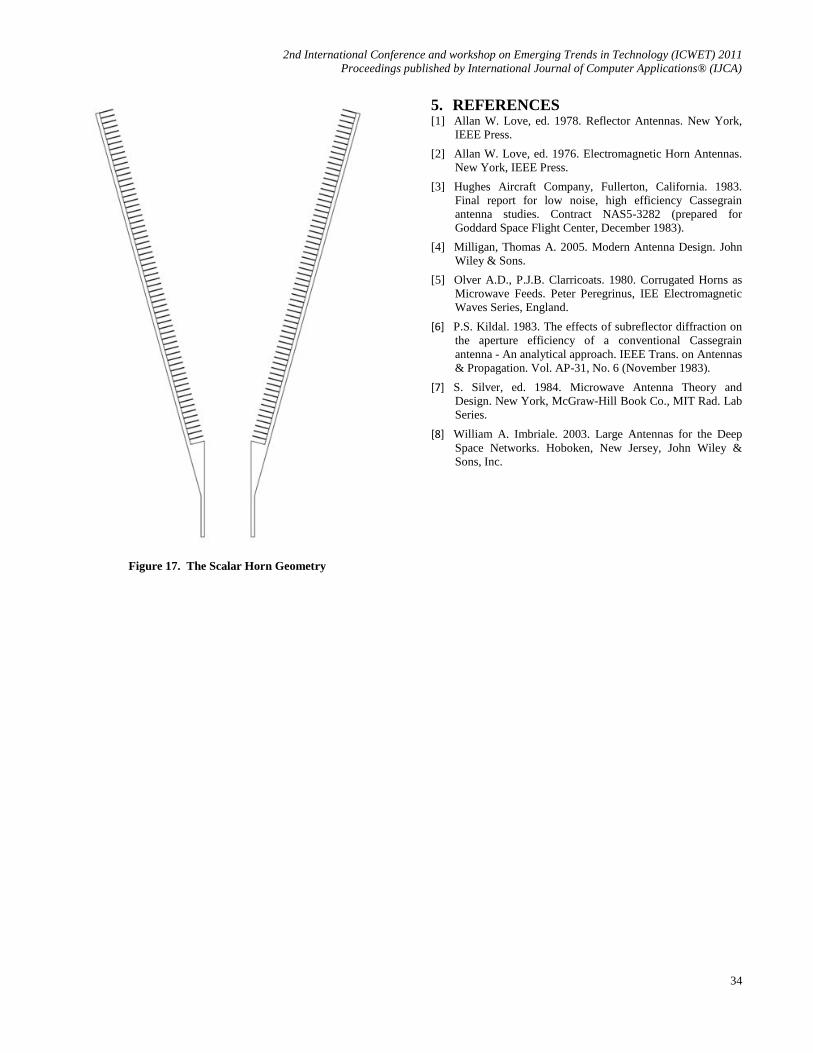
width ratio, t/b = 0.1. It gives, b = slot width = 0.7811 mm, t =
ridge width = 0.07811 mm, dn = slot-depth = 2.15 mm. The
Scalar Horn geometry is shown in Figure 17.
For simulating Conical Corrugated Horn antenna, software that
supports Mode-Matching Techniques plus Method of Moments
is considered as an accurate software. Some authors have
suggested the use of Ansoft HFSS for obtaining the radiation
diagram. HFSS works on Finite Elements Method.
The 3D Modeler Window shows the horn geometry in HFSS.
PML (Perfectly Matched Layer) is used around the horn
structure. Several layers of specialized materials that can absorb
the outgoing waves construct PML. Driven model solution is
used for the simulation.
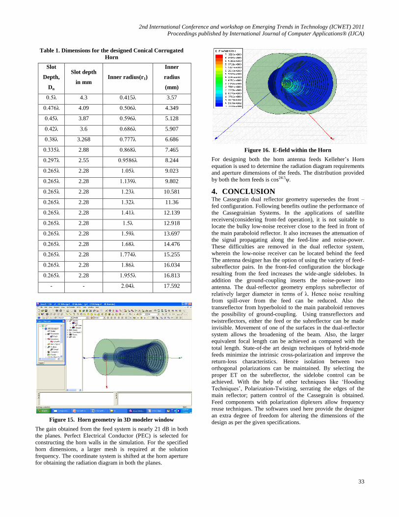
Figure 12. Conical Corrugated Horn involving Throat
Region
Figure 13. E-plane Radiation Diagram
Figure 14. H-plane Radiation Diagram
2nd International Conference and workshop on Emerging Trends in Technology (ICWET) 2011
Proceedings published by International Journal of Computer Applications® (IJCA)
33
Table 1. Dimensions for the designed Conical Corrugated
Horn
Slot
Depth,
Dn
Slot depth
in mm Inner radius(r1)
Inner
radius
(mm)
0.5λ 4.3 0.415λ 3.57
0.476λ 4.09 0.506λ 4.349
0.45λ 3.87 0.596λ 5.128
0.42λ 3.6 0.686λ 5.907
0.38λ 3.268 0.777λ 6.686
0.335λ 2.88 0.868λ 7.465
0.297λ 2.55 0.9586λ 8.244
0.265λ 2.28 1.05λ 9.023
0.265λ 2.28 1.139λ 9.802
0.265λ 2.28 1.23λ 10.581
0.265λ 2.28 1.32λ 11.36
0.265λ 2.28 1.41λ 12.139
0.265λ 2.28 1.5λ 12.918
0.265λ 2.28 1.59λ 13.697
0.265λ 2.28 1.68λ 14.476
0.265λ 2.28 1.774λ 15.255
0.265λ 2.28 1.86λ 16.034
0.265λ 2.28 1.955λ 16.813
- - 2.04λ 17.592
Figure 15. Horn geometry in 3D modeler window
The gain obtained from the feed system is nearly 21 dB in both
the planes. Perfect Electrical Conductor (PEC) is selected for
constructing the horn walls in the simulation. For the specified
horn dimensions, a larger mesh is required at the solution
frequency. The coordinate system is shifted at the horn aperture
for obtaining the radiation diagram in both the planes.
Figure 16. E-field within the Horn
For designing both the horn antenna feeds Kelleher’s Horn
equation is used to determine the radiation diagram requirements
and aperture dimensions of the feeds. The distribution provided
by both the horn feeds is cos24.5ψ.
4. CONCLUSION The Cassegrain dual reflector geometry supersedes the front –
fed configuration. Following benefits outline the performance of
the Cassegrainian Systems. In the applications of satellite
receivers(considering front-fed operation), it is not suitable to
locate the bulky low-noise receiver close to the feed in front of
the main paraboloid reflector. It also increases the attenuation of
the signal propagating along the feed-line and noise-power.
These difficulties are removed in the dual reflector system,
wherein the low-noise receiver can be located behind the feed
The antenna designer has the option of using the variety of feed-
subreflector pairs. In the front-fed configuration the blockage
resulting from the feed increases the wide-angle sidelobes. In
addition the ground-coupling inserts the noise-power into
antenna. The dual-reflector geometry employs subreflector of
relatively larger diameter in terms of λ. Hence noise resulting
from spill-over from the feed can be reduced. Also the
transreflector from hyperboloid to the main paraboloid removes
the possibility of ground-coupling. Using transreflectors and
twistreflectors, either the feed or the subreflector can be made
invisible. Movement of one of the surfaces in the dual-reflector
system allows the broadening of the beam. Also, the larger
equivalent focal length can be achieved as compared with the
total length. State-of-the art design techniques of hybrid-mode
feeds minimize the intrinsic cross-polarization and improve the
return-loss characteristics. Hence isolation between two
orthogonal polarizations can be maintained. By selecting the
proper ET on the subreflector, the sidelobe control can be
achieved. With the help of other techniques like ‘Hooding
Techniques’, Polarization-Twisting, serrating the edges of the
main reflector; pattern control of the Cassegrain is obtained.
Feed components with polarization diplexers allow frequency
reuse techniques. The softwares used here provide the designer
an extra degree of freedom for altering the dimensions of the
design as per the given specifications.
2nd International Conference and workshop on Emerging Trends in Technology (ICWET) 2011
Proceedings published by International Journal of Computer Applications® (IJCA)
34
Figure 17. The Scalar Horn Geometry
5. REFERENCES [1] Allan W. Love, ed. 1978. Reflector Antennas. New York,
IEEE Press.
[2] Allan W. Love, ed. 1976. Electromagnetic Horn Antennas.
New York, IEEE Press.
[3] Hughes Aircraft Company, Fullerton, California. 1983.
Final report for low noise, high efficiency Cassegrain
antenna studies. Contract NAS5-3282 (prepared for
Goddard Space Flight Center, December 1983).
[4] Milligan, Thomas A. 2005. Modern Antenna Design. John
Wiley & Sons.
[5] Olver A.D., P.J.B. Clarricoats. 1980. Corrugated Horns as
Microwave Feeds. Peter Peregrinus, IEE Electromagnetic
Waves Series, England.
[6] P.S. Kildal. 1983. The effects of subreflector diffraction on
the aperture efficiency of a conventional Cassegrain
antenna - An analytical approach. IEEE Trans. on Antennas
& Propagation. Vol. AP-31, No. 6 (November 1983).
[7] S. Silver, ed. 1984. Microwave Antenna Theory and
Design. New York, McGraw-Hill Book Co., MIT Rad. Lab
Series.
[8] William A. Imbriale. 2003. Large Antennas for the Deep
Space Networks. Hoboken, New Jersey, John Wiley &
Sons, Inc.


![Designing Optimized Cassegrain with Balanced Feed · pencil beam with significantly low side lobe levels, the paraboloid[7] is the most suitable type when used with a feed element](https://img.pdfslide.net/doc/110x75/5f527079208b247b4517e3ce/designing-optimized-cassegrain-with-balanced-feed-pencil-beam-with-significantly.jpg)