Embed Size (px)
Citation preview

© 1995 – 1999 ACI US Inc • 3031 Tisch Way • Suite 900 • San Jose • CA 95128 • http://www.acius.com
Designing Relational Databases
[email protected] 1.0.2 AcademicCourse Developed By:
Jeff BrowningKent Wilbur
Revised by:Steve Hussey

Designing Relational Databases
License 1Important License Information .................................................................................................................1
Introduction 1Welcome .............................................................................................................................................1How the guide works ............................................................................................................................1
What you will be doing while working through this guide ....................................................................1Guide agenda ................................................................................................................................2
Conventions .........................................................................................................................................2Table: 4D Programming Styles ..........................................................................................................3
Phases of software development .............................................................................................................3Benefits of formal software design ...........................................................................................................4
Table: Phase Introduced ...................................................................................................................4Understanding the Relational Database Model 6
What is a database? ............................................................................................................................6Exercises: Identifying Databases 6Exercise 2.1 ........................................................................................................................................6What is a database management system? ...............................................................................................7What is a relational database? ..............................................................................................................8
Table: Part .....................................................................................................................................8Basic relational database terminology .....................................................................................................9
Table .............................................................................................................................................9Table: Part .....................................................................................................................................9Column ........................................................................................................................................10Table: Account .............................................................................................................................11Row ............................................................................................................................................11Primary key ..................................................................................................................................12Table: Part ...................................................................................................................................12Table: Warehouse ........................................................................................................................12Table: Stock .................................................................................................................................12Table: Person ................................................................................................................................13Table: Person ................................................................................................................................14Table: Person ................................................................................................................................14Table: Person ................................................................................................................................15Relations ......................................................................................................................................15Table: Stock .................................................................................................................................15Table: Stock/Part Description View .................................................................................................16Table: Person I ..............................................................................................................................17Table: .........................................................................................................................................18Table: Person 2 .............................................................................................................................18Review ........................................................................................................................................18
Exercises: Identifying tables, columns and keys 19Exercise 2.2 ......................................................................................................................................19
Table: Part ...................................................................................................................................19Exercise 2.3 ......................................................................................................................................20
Table: Item ...................................................................................................................................20Table: Order ................................................................................................................................20
Exercise 2.4 ......................................................................................................................................21Table: Item ...................................................................................................................................21Table: Order ................................................................................................................................21Table: Order Item ..........................................................................................................................21
Exercise 2.5 ......................................................................................................................................22
© 1995 – 1999 ACI US Inc • 3031 Tisch Way • Suite 900 • San Jose • CA 95128 • http://www.acius.com i

Designing Relational Databases
Table: Person ................................................................................................................................22What is a relational database good for? 23
Table: Financial Variable ...............................................................................................................24Formal representation of tables 26
Exercises: Drawing entity/attribute views 26Exercise 4.1 ......................................................................................................................................26
Table: Stock .................................................................................................................................26Table: Item ...................................................................................................................................26Table: Order ................................................................................................................................27Table: Order Item ..........................................................................................................................27
Normalization 28What is normalization? .......................................................................................................................28Why normalize? .................................................................................................................................28Functional dependency ........................................................................................................................29
Table: Common Stock ....................................................................................................................29Table: Stock .................................................................................................................................29
Exercises: Recognizing Functional Dependencies 30Exercise 5.1 ......................................................................................................................................30
Table: Inventory ............................................................................................................................30Table: Feeding Plan .......................................................................................................................30
First Normal Form ...............................................................................................................................31Table: Employee ...........................................................................................................................31
Exercises: First Normal Form 32Exercise 5.2 ......................................................................................................................................32
Table: Personnel Evaluation ............................................................................................................33Exercise 5.3 ......................................................................................................................................34
Table: Monthly Data ......................................................................................................................34Table: Quarterly Data ....................................................................................................................35Table: Annual Data .......................................................................................................................36
Second Normal Form ..........................................................................................................................36Table: Employee ID .......................................................................................................................36Table: Employee ...........................................................................................................................37Table: Project ...............................................................................................................................37Table: Assignment .........................................................................................................................37
Exercises: Second normal form 38Exercise 5.4 ......................................................................................................................................38
Table: Employee ...........................................................................................................................38Table: Project ...............................................................................................................................38Table: Assignment .........................................................................................................................38Table: Policy .................................................................................................................................39
Third Normal Form .............................................................................................................................39Table: Employee ...........................................................................................................................39Table: Employee ...........................................................................................................................40Table: Department .........................................................................................................................40Table: Work .................................................................................................................................41Table: Work .................................................................................................................................41Table: Work .................................................................................................................................41Table: Artist ..................................................................................................................................42Table: Work .................................................................................................................................42Table: Artist ..................................................................................................................................42
Exercises: Third normal form 43
© 1995 – 1999 ACI US Inc • 3031 Tisch Way • Suite 900 • San Jose • CA 95128 • http://www.acius.com ii
Designing Relational Databases
Exercise 5.5 ......................................................................................................................................43Table: Employee ...........................................................................................................................43
Further normalization ..........................................................................................................................43Review ..............................................................................................................................................43Exercises: Normalization 44Exercise 5.6 ......................................................................................................................................44
Table: Bee ....................................................................................................................................44Exercise 5.7 ......................................................................................................................................45Exercise 5.8 ......................................................................................................................................45
Table: Sting ..................................................................................................................................45Exercise 5.9 ......................................................................................................................................46Exercise 5.10 ....................................................................................................................................46
Modeling the database 48What is an entity/relationship diagram? ...............................................................................................48Why diagram? ...................................................................................................................................48Technique ..........................................................................................................................................48Why entities and relationships? ............................................................................................................49Examples ...........................................................................................................................................50Review ..............................................................................................................................................51Exercises: Creating entity/relationship diagrams 51Exercise 6.1 ......................................................................................................................................51Exercise 6.2 ......................................................................................................................................51Exercise 6.3 ......................................................................................................................................52Exercise 6.5 ......................................................................................................................................52Exercise 6.6 ......................................................................................................................................52Exercise 6.7 ......................................................................................................................................52Exercise 6.8 ......................................................................................................................................52Exercise 6.9 ......................................................................................................................................52Exercise 6.10 ....................................................................................................................................52
Discovering entities, attributes and relationships 54A client interview process ....................................................................................................................54
Table: MAN .................................................................................................................................54Differing users’ views ..........................................................................................................................56Naming conflicts ................................................................................................................................57Exercises: Client interview process 58Exercise 7.1 ......................................................................................................................................58
Table: Client .................................................................................................................................59Table: Case ..................................................................................................................................59Table: Ad .....................................................................................................................................60
Exercise 7.2 ......................................................................................................................................61More advanced modeling concepts 62
Storing historical data .........................................................................................................................62Table: Marriage ............................................................................................................................63Table: Part Price ............................................................................................................................63
Relating an entity to itself (bill of materials) .............................................................................................63Table: Part ...................................................................................................................................64Table: Component Assembly ..........................................................................................................64Table: Component Assembly ..........................................................................................................64
Storing derived data ...........................................................................................................................65Table: Customer ............................................................................................................................65Table: Invoice ...............................................................................................................................66
© 1995 – 1999 ACI US Inc • 3031 Tisch Way • Suite 900 • San Jose • CA 95128 • http://www.acius.com iii

Designing Relational Databases
Table: Customer ............................................................................................................................66Table: Invoice ...............................................................................................................................67Table: Customer ............................................................................................................................68Table: Customer ............................................................................................................................69Table: Horse .................................................................................................................................70
Exercises: Advanced Modeling Concepts 71Exercise 8.1 ......................................................................................................................................71Exercise 8.2 ......................................................................................................................................71
Table: Run ....................................................................................................................................71Table: Heat ..................................................................................................................................71
Exercise 8.3 ......................................................................................................................................72Completing a Database Design Specification 73
Definitions .........................................................................................................................................73Entity definitions ...........................................................................................................................73Attribute definitions .......................................................................................................................73Relationship definitions ..................................................................................................................73
Naming conventions ...........................................................................................................................74Identifying data storage and transaction requirements .............................................................................75
Table: Work .................................................................................................................................77Table: Artist ..................................................................................................................................77
Identifying business rules and other constraints .......................................................................................77Table: Part Price ............................................................................................................................78Table: Price Change Type List .........................................................................................................78
Frequent search and sort parameters .....................................................................................................78Table: Part ...................................................................................................................................79Table: Warehouse ........................................................................................................................79Table: Stock .................................................................................................................................79
Security .............................................................................................................................................80Table: Work .................................................................................................................................81Table: Artist ..................................................................................................................................81
Finalizing the Database Design Specification .........................................................................................81Exercises: Finalizing the database design specification 81Exercise 9.1 ......................................................................................................................................81
Optimizing the database design 85Trade-offs in performance ....................................................................................................................85Performance issues ..............................................................................................................................86
Storage considerations ..................................................................................................................86Loading records ............................................................................................................................86Inserting, updating and deleting records ..........................................................................................86Searching and sorting (single-field) .................................................................................................87Querying and sorting (multi-field) ....................................................................................................87Querying and sorting (cross-table) ...................................................................................................87Searching and sorting (calculated data) ...........................................................................................87
The results of indexing .........................................................................................................................88Denormalizing 1:M relationships ..........................................................................................................88When you should create a 1:1 relationship ...........................................................................................89
The “Fat” table. ............................................................................................................................89Table: Fat Table ............................................................................................................................90Table: Students .............................................................................................................................90Table: Employees ..........................................................................................................................90Large amounts of seldom used data. ...............................................................................................91
© 1995 – 1999 ACI US Inc • 3031 Tisch Way • Suite 900 • San Jose • CA 95128 • http://www.acius.com iv

Designing Relational Databases
Storing derived data (reprise) ...............................................................................................................91Storing concatenated fields ..................................................................................................................92Repeating Fields .................................................................................................................................92Empty first table ..................................................................................................................................92Exercises: Optimizing the database design 93Exercise 10.1 ....................................................................................................................................93Exercise 10.2 ....................................................................................................................................93
Creating the physical database structure 95Creating groups .................................................................................................................................95Converting entities to tables .................................................................................................................96Adding fields .....................................................................................................................................96
Creating primary key fields ............................................................................................................97Entering non-key fields ...................................................................................................................99Establishing relations .....................................................................................................................99
Exercises: Creating the physical database structure 101Exercise 11.1 ..................................................................................................................................101Exercise 11.2 ..................................................................................................................................101Exercise 11.3 ..................................................................................................................................101Exercise 11.4 ..................................................................................................................................101
Final Exercise 102Moscow State ..................................................................................................................................102
Table: Data to be Stored ..............................................................................................................102Appendix A: References 104
Reference 1 . . . . . . . . . . . . . . . . . . . . . . . . . . . . . . . . . . . . . . . . . . . . . . . . . . . . . . . . . . . . . . . . . . .104Reference 2 . . . . . . . . . . . . . . . . . . . . . . . . . . . . . . . . . . . . . . . . . . . . . . . . . . . . . . . . . . . . . . . . . . .104Reference 3 . . . . . . . . . . . . . . . . . . . . . . . . . . . . . . . . . . . . . . . . . . . . . . . . . . . . . . . . . . . . . . . . . . .104Reference 4 . . . . . . . . . . . . . . . . . . . . . . . . . . . . . . . . . . . . . . . . . . . . . . . . . . . . . . . . . . . . . . . . . . .104Reference 5 . . . . . . . . . . . . . . . . . . . . . . . . . . . . . . . . . . . . . . . . . . . . . . . . . . . . . . . . . . . . . . . . . . .104Reference 6 . . . . . . . . . . . . . . . . . . . . . . . . . . . . . . . . . . . . . . . . . . . . . . . . . . . . . . . . . . . . . . . . . . .105
Appendix B: Solutions to exercises 106Chapter 2 exercises 106Exercise 2.1 ....................................................................................................................................106Exercise 2.2 ....................................................................................................................................106Exercise 2.3 ....................................................................................................................................107Exercise 2.4 ....................................................................................................................................107Exercise 2.5 ....................................................................................................................................107Chapter 4 exercises 109Exercise 4.1 ....................................................................................................................................109Chapter 5 exercises 109Exercise 5.1 ....................................................................................................................................109
Table: Item .................................................................................................................................109Table: Order ..............................................................................................................................109Table: Order Item ........................................................................................................................109
Exercise 5.2 ....................................................................................................................................110Table: Patient Record ...................................................................................................................111Table: Appointments ....................................................................................................................111Table: Health History ...................................................................................................................111
Exercise 5.3 ....................................................................................................................................112Table: Periodic Data ....................................................................................................................112
Exercise 5.4 ....................................................................................................................................113
© 1995 – 1999 ACI US Inc • 3031 Tisch Way • Suite 900 • San Jose • CA 95128 • http://www.acius.com v

Designing Relational Databases
Table: Policy ...............................................................................................................................113Table: Carrier .............................................................................................................................113Table: Customer ..........................................................................................................................113
Exercise 5.5 ....................................................................................................................................114Exercise 5.6 ....................................................................................................................................114
Table: Employee .........................................................................................................................114Table: Department .......................................................................................................................114Table: Bee ..................................................................................................................................115Table: Sting ................................................................................................................................115Table: Hive ................................................................................................................................115Table: Flower .............................................................................................................................115Table: Pollination ........................................................................................................................115
Exercise 5.7 ....................................................................................................................................116Table: Person ..............................................................................................................................116Table: Shepherd .........................................................................................................................116Table: Pen ..................................................................................................................................116
Exercise 5.8 ....................................................................................................................................117Table: Sheep ..............................................................................................................................117Table: Wizard ............................................................................................................................117Table: Club ................................................................................................................................117
Exercise 5.9 ....................................................................................................................................118Table: Spell ................................................................................................................................118Table: Magician Club ..................................................................................................................118Table: Magician Spell .................................................................................................................118
Exercise 5.10 ..................................................................................................................................119Table: Trainer .............................................................................................................................119Table: Horse Barn .......................................................................................................................119Table: Horse ...............................................................................................................................119Table: Painter .............................................................................................................................120Table: Club ................................................................................................................................120Table: Medium ...........................................................................................................................120Table: Painter Club ......................................................................................................................120Table: Painter Medium .................................................................................................................120
Chapter 6 exercises 121Exercise 6.1 ....................................................................................................................................121Exercise 6.2 ....................................................................................................................................121Exercise 6.3 ....................................................................................................................................121Exercise 6.5 ....................................................................................................................................122Exercise 6.6 ....................................................................................................................................122Exercise 6.7 ....................................................................................................................................123Exercise 6.8 ....................................................................................................................................123Exercise 6.9 ....................................................................................................................................124Exercise 6.10 ..................................................................................................................................124
Table: Pirate ...............................................................................................................................125Table: Pirate Ship ........................................................................................................................125Table: Merchant Ship ..................................................................................................................125Table: Plundering ........................................................................................................................125
Chapter 7 exercises 126Exercise 7.1 ....................................................................................................................................126
Table: Advertiser .........................................................................................................................128Table: Client ...............................................................................................................................130
© 1995 – 1999 ACI US Inc • 3031 Tisch Way • Suite 900 • San Jose • CA 95128 • http://www.acius.com vi

Designing Relational Databases
Table: Case ................................................................................................................................131Table: Advertiser .........................................................................................................................131Table: Ad ...................................................................................................................................131Table: Physician ..........................................................................................................................131Table: Defendant ........................................................................................................................132Table: Opposing Atty ..................................................................................................................132
Exercise 7.2 ....................................................................................................................................133Table: Publisher ..........................................................................................................................134Table: Reporter ...........................................................................................................................134Table: Story ................................................................................................................................135Table: Subject .............................................................................................................................135Table: Subject Reference ..............................................................................................................135Table: Job ..................................................................................................................................135
Chapter 8 exercises 136Exercise 8.1 ....................................................................................................................................136
Table: Job ..................................................................................................................................137Table: Pirate Ship ........................................................................................................................137
Exercise 8.2 ....................................................................................................................................138Table: Person ..............................................................................................................................138Table: Marriage ..........................................................................................................................139Table: Offspring ..........................................................................................................................139
Exercise 8.3 ....................................................................................................................................140Table: Player ..............................................................................................................................140Table: Team ...............................................................................................................................141Table: Season .............................................................................................................................141Table: Team Season ....................................................................................................................141Table: Player Season ...................................................................................................................141Table: Game ..............................................................................................................................142Table: Team Game ......................................................................................................................142Table: Player Game ....................................................................................................................142
Chapter 9 exercises 144Exercise 9.1 ....................................................................................................................................144
Table: Client ...............................................................................................................................149Table: Case ................................................................................................................................149Table: Client Case .......................................................................................................................150Table: Advertiser .........................................................................................................................150Table: Ad ...................................................................................................................................150Table: Physician ..........................................................................................................................150Table: Party ...............................................................................................................................150Table: Attorney ...........................................................................................................................151Table: Party Case Attorney ...........................................................................................................151Table: Client ...............................................................................................................................151Table: Case ................................................................................................................................151Table: Client Case .......................................................................................................................152Table: Advertiser .........................................................................................................................152Table: Ad ...................................................................................................................................152Table: Physician ..........................................................................................................................152Table: Party ................................................................................................................................153Table: Attorney ...........................................................................................................................153Table: Party Case Attorney ...........................................................................................................153Table: Case ................................................................................................................................153
© 1995 – 1999 ACI US Inc • 3031 Tisch Way • Suite 900 • San Jose • CA 95128 • http://www.acius.com vii

Designing Relational Databases
Table: Client ...............................................................................................................................153Table: Case ................................................................................................................................154Table: Client Case .......................................................................................................................154Table: Advertiser .........................................................................................................................155Table: Ad ...................................................................................................................................155Table: Physician ..........................................................................................................................155Table: Party ................................................................................................................................156Table: Attorney ...........................................................................................................................156Table: Party Case Attorney ...........................................................................................................156Table: Client ...............................................................................................................................157Table: Case ................................................................................................................................157Table: Client Case .......................................................................................................................158Table: Advertiser .........................................................................................................................158Table: Ads .................................................................................................................................158Table: Physicians ........................................................................................................................158Table: Party ................................................................................................................................159Table: Party Case Attorney ...........................................................................................................159
Chapter 10 exercises 160Exercise 10.1 ..................................................................................................................................160
Table: Products ...........................................................................................................................160Table: Customers ........................................................................................................................160Table: Invoices ............................................................................................................................160Table: Line Items .........................................................................................................................161
Exercise 10.2 ..................................................................................................................................162Table: Products ...........................................................................................................................162Table: Customers ........................................................................................................................162Table: Invoices ............................................................................................................................162
Chapter 11 exercises 163Exercise 11.1 ..................................................................................................................................164Exercise 11.2 ..................................................................................................................................164Exercise 11.3 ..................................................................................................................................165Exercise 11.4 ..................................................................................................................................165Chapter 12 exercises 165Exercise 12.1 ..................................................................................................................................165
© 1995 – 1999 ACI US Inc • 3031 Tisch Way • Suite 900 • San Jose • CA 95128 • http://www.acius.com viii

© 1995 – 1999 ACI US Inc • 3031 Tisch Way • Suite 900 • San Jose • CA 95128 • http://www.acius.com
Designing Relational Databases
License
License
The Software described in this manual is governed by the grant of license in the ACIProduct Line License Agreement provided with the Software in this package. The Soft-ware, this manual, and all documentation included with the Software are copyrighted.
This guide ‘Designing Relational databases’ may be reproduced and distributed to staffand students of eligible academic institutions as defined in the ACI document ‘AcademicEligibility.PDF’. The guide may not be sold.
4th Dimension, 4D, the 4D logo, 4D Server, ACI, and the ACI logo are registered trade-marks of ACI SA. Microsoft and Windows are registered trademarks of Microsoft Corpo-ration.
Apple, Macintosh, Mac, Power Macintosh, Mac OS, Laser Writer, Image Writer, ResEdit,and QuickTime are trademarks or registered trademarks of Apple Computer, Inc.
All other referenced trade names are trademarks or registered trademarks of their respec-tive holders.
Important License Information
Use of 4th Dimension Software is subject to the ACI Product Line License Agreement,which is provided in electronic form with the Software. Please read the ACI Product LineLicense Agreement carefully before completely installing or using 4th Dimension Soft-ware.

Designing Relational Databases
Introduction
1 Introduction
1.1 Welcome
The purpose of this guide is to teach you how to successfully design relational databases.While this guide will cover some concepts which are specific to 4th Dimension (“4D”),most of the concepts covered in this guide could be applied to other relational databasemanagement systems.
At the conclusion of this guide, you should be able to interview a user who wishes todevelop a relational database system, and using the skills obtained from this guide, suc-cessfully translate his or her requirements into a workable design.
You should then be able to produce a set of drawings which will communicate to the user(and to any other developer) the nature of your design.
1.2 How the guide works
1.2.1 What you will be doing while working through this guide
Using this guide you will examine the relational database model in detail. In the process,the guide will define lots of technical terms — don’t let this throw you. Relational data-base theory is mostly common sense.
• You are also going to be drawing pictures of database designs while completing thevarious exercises contained in this guide. There will be lots of exercises. In this guideyou will be using a technology known as a pencil and paper. There are a variety ofCASE tools on the market, none of which is any better for our purposes than a penciland paper. The 4D structure editor is sometimes used as a simple CASE tool. This hassome disadvantages:
• It is unforgiving (tables and fields cannot be deleted).
• The location of relation lines cannot be controlled.
• Many things, such as primary keys, are not clearly identified.
A pencil and paper, on the other hand, has the following advantages:
• Very portable.
• Highly correctable (the eraser serves this function well).
• Low power requirement.
• Very user-friendly (flat learning curve).
Thus, this guide will not generally be “hands-on” as that term is normally defined (mean-ing working with computer software). However, it will be very much “hands-on” in thesense that you will be working actively throughout the guide to design databases which
© 1995 – 1999 ACI US Inc • 3031 Tisch Way • Suite 900 • San Jose • CA 95128 • http://www.acius.com 1
Designing Relational Databases
Introduction
meet real-world demands.
Bear in mind when working these exercises that there may be more than one correctanswer. Designing relational databases is as much of an art as a science. Usually, this bookwill point out when more than one answer is correct. In that case, the book will give onecorrect answer. If you need confirmation that your answer is correct, check with yourtutor.
Towards the end of the guide, you will begin to use 4D more as you translate designs intophysical database structures. At the conclusion of the guide, you will look at optimizationissues involved in building relational structures in 4D. During this period, you may wantto use 4D more extensively.
1.2.2 Guide agenda
You will be taking a look at the theory of the relational database model and definingterms. Later you will begin looking in detail at the rules of database design, using a con-cept called normalization. While doing so, you will look at some relatively good and baddatabase designs.
After that, you will begin to examine a way to represent databases in pictures, using atechnique called an entity relationship diagram. During this portion of the guide, you willbegin to turn to more advanced database design problems.
After that you will begin examining the process of capturing the business rules and con-straints which need to be built into the database design. You will also read about the issuesof choosing workable names. Then you will cover security as a part of the design process.Issues of performance, and the various “tricks and traps” associated with 4D’s implemen-tation of the relational model will be discussed. You will learn when to break or bend therules in order to gain better performance. Finally, the guide will conclude with a series ofexercises which will apply everything you have learned in the guide.
Thus, the guide can be broken up into two areas. The first part is almost entirely con-cerned with the design phase of database development. Only later will you delve into theareas of construction when you examine optimization and implementation issues. Thematerials will frequently make this distinction. The statement that you are designing, notprogramming is your clue that you are covering areas where 4D may cause us to eventu-ally bend or break the rules. However, it is much easier (and safer!) to break the rules afteryou have created a correct and complete design. Our recommendation will always be tocomplete the design process first, and then look at areas where the design needs to beadjusted to meet performance objectives.
1.3 Conventions
This guide material will use certain typographic conventions, including:
© 1995 – 1999 ACI US Inc • 3031 Tisch Way • Suite 900 • San Jose • CA 95128 • http://www.acius.com 2
Designing Relational Databases
Introduction
• The following italic font indicates a term that is being defined or explained for thefirst time.
• The following normal font refers to a database object like a table or column
• Characters you type are shown in this typeface.
• Example: Type Johnson into the Name field.
• Special keys on your keyboard are shown like this: Enter and Return.
• Choosing an item from a menu is described like this:
• Choose File ¬ Open
• Explanation: From the File menu, choose the Open item.
• 4D programming items are shown consistent with the way they are displayed in 4D:
1.4 Phases of software development
This guide does not cover programming details to any significant degree. Rather, thisguide is concerned with the design phase of software development.
Software development includes the following six phases:
• System specification
• Requirements analysis
• Design
• Construction (coding)
• Testing
• Maintenance
System specification refers to the process of discovering that a new system is needed, anddescribing the problem it is designed to solve in broad terms. This is primarily a businessissue, and is not covered by this guide.
During requirements analysis the details of what the software is supposed to do is fleshedout. This phase completes the definition of what the software is going to do. The howoccurs next. Again, this phase is not covered by this guide.
Design refers to the process of creating a plan for how the software will be built, includingwhere the data is to be stored, the sources of data, and how the data flows through the sys-
4D Programming Styles
[Customers]State Field
ALERT Command
MyProcedure Procedure
© 1995 – 1999 ACI US Inc • 3031 Tisch Way • Suite 900 • San Jose • CA 95128 • http://www.acius.com 3
Designing Relational Databases
Introduction
tem. It is this phase, particularly with respect to identifying the data, and how it will bestored, which is the primary subject of this guide.
Construction refers to the process of actually building the software. It is this phase thatmost ACI University training classes address. In addition, you will move into this phaseduring the last section of this guide.
Testing is the process of evaluating software to confirm that it does, in fact, do what it issupposed to do. The formal testing phase is not covered explicitly in this guide (althoughtesting as a part of construction is certainly covered).
Maintenance is the on-going process of supporting the software while it is in production.Again, this phase is not explicitly covered by this guide.
Each of these phases may occur in a relatively formal or informal way. For example, in thecase of a small ad hoc system for the use of a single user (who often happens to be the pro-grammer), the entire process may occur in the programmer’s head.
On the other hand, in a large, multi-user client server system for a large enterprise, thesephases will probably occur in a much more formal way. In fact, some of the phases may befurther broken down, Design might be broken down into architectural design anddetailed design, for example.
1.5 Benefits of formal software design
It is a basic principle of computer science that all of these phases occur on the develop-ment of any system regardless of whether the system designers are aware of it or not. It hasalso been proven that some formality in the process of software development generallyresults in dramatic improvements in the resulting software, as well as reducing the cost ofdevelopment.
In the case of the small ad hoc system described above, there is relatively little conse-quence of a major mistake in design. This is simply because the entire program can becompletely rewritten with relatively little penalty.
As the size of a software development project grows, the consequences of a basic designerror grow exponentially.
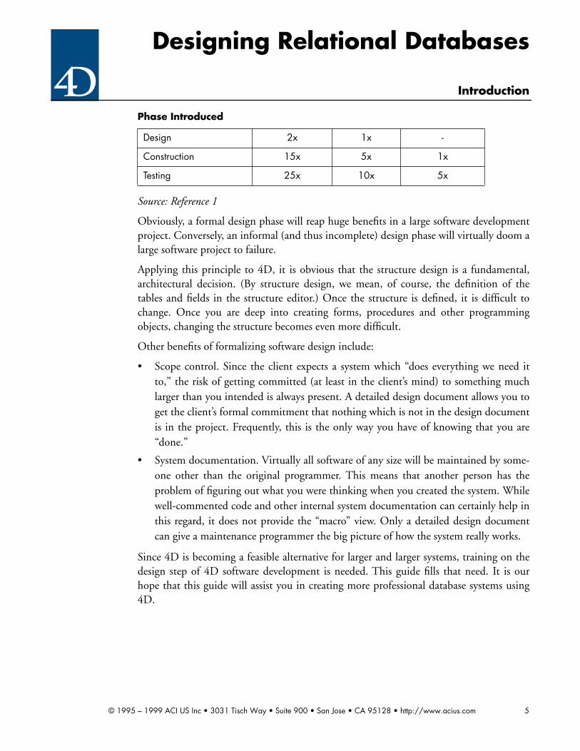
The following chart graphically illustrates the problem. What is shown is the relative costof correcting a problem given when it was introduced in the software development pro-cess, and when it was detected.
Phase Introduced
Phase detected Requirements Design Construction
Requirements 1x - -
© 1995 – 1999 ACI US Inc • 3031 Tisch Way • Suite 900 • San Jose • CA 95128 • http://www.acius.com 4
Designing Relational Databases
Introduction
Source: Reference 1
Obviously, a formal design phase will reap huge benefits in a large software developmentproject. Conversely, an informal (and thus incomplete) design phase will virtually doom alarge software project to failure.
Applying this principle to 4D, it is obvious that the structure design is a fundamental,architectural decision. (By structure design, we mean, of course, the definition of thetables and fields in the structure editor.) Once the structure is defined, it is difficult tochange. Once you are deep into creating forms, procedures and other programmingobjects, changing the structure becomes even more difficult.
Other benefits of formalizing software design include:
• Scope control. Since the client expects a system which “does everything we need itto,” the risk of getting committed (at least in the client’s mind) to something muchlarger than you intended is always present. A detailed design document allows you toget the client’s formal commitment that nothing which is not in the design documentis in the project. Frequently, this is the only way you have of knowing that you are“done.”
• System documentation. Virtually all software of any size will be maintained by some-one other than the original programmer. This means that another person has theproblem of figuring out what you were thinking when you created the system. Whilewell-commented code and other internal system documentation can certainly help inthis regard, it does not provide the “macro” view. Only a detailed design documentcan give a maintenance programmer the big picture of how the system really works.
Since 4D is becoming a feasible alternative for larger and larger systems, training on thedesign step of 4D software development is needed. This guide fills that need. It is ourhope that this guide will assist you in creating more professional database systems using4D.
Design 2x 1x -
Construction 15x 5x 1x
Testing 25x 10x 5x
Phase Introduced
© 1995 – 1999 ACI US Inc • 3031 Tisch Way • Suite 900 • San Jose • CA 95128 • http://www.acius.com 5

Designing Relational Databases
Understanding the Relational Database Model
2 Understanding the Relational Database Model
2.1 What is a database?
A database is an organized or structured collection of data. It contains the data necessaryfor some purpose or purposes. The data is arranged to allow a set of activities to occur,and so that it can be accessed and altered in an efficient manner.
Source: Reference 2
Obviously, this definition does not require that the database be stored on a computer.Some practical examples of databases include:
• Commercial phone book
• Rolodex
• Recipe card box
• School teacher’s grade folder
Other examples abound. Can you think of some?
Exercises: Identifying Databases
Exercise 2.1
Frequently it is helpful to understand what something is by understanding what it is not.
Take the following example: A university wants to recruit new students, so it puts upposters on a large number of high school campuses soliciting letters from students. Itreceives a large number of letters in response. These letters generally contain the student’sname, address, city, state and zip code. Some also contain other information such as thestudent’s high school, current grade level, SAT scores and grade point average. Whenreceived the letters were placed in a filing cabinet.
• Is this a database? If so, why? If not, why not?
• If the university staff wants to find a particular student’s letter, could they do so easily?
• If the university staff wants to sort the letters by state and city, could they do so easily?
Realizing the error of its ways, the university now includes tear-off cards on the posterscontaining blanks for the student to fill in the following information:
• Last name
• First name
• Street address
• City
• State
© 1995 – 1999 ACI US Inc • 3031 Tisch Way • Suite 900 • San Jose • CA 95128 • http://www.acius.com 6

Designing Relational Databases
Understanding the Relational Database Model
• Zip
• Phone
• High School
• Current grade level
• SAT scores
• Grade point average
Again, the university receives a large number of cards in response, all of which it stores ina card filing box.
• Is this a database? If so, why? If not, why not?
• If the university staff wants to find a particular student’s card, could they do so easily?
• If the university staff wants to sort the cards by state and city, could they do so easily?
2.2 What is a database management system?
A database management system is software that manages data in an organized or struc-tured way.
Source: Reference 2
This definition follows very logically from the definition of a database given above. Com-mon features offered by most database management systems include:
• A way to define containers (typically tables and columns) to hold data.
• Commands and other features allowing the user to search for and sort the data.
• Commands allowing the user to insert new data, update and delete existing data.
• A GUI builder, or other feature allowing the user to create forms to view the data
• A report generator allowing data to be printed
• Enforcement of relational integrity and business rule constraints
• Management of simultaneous data access among multiple users
Source: Reference 2
Based upon these common features, it is readily apparent that 4D is a database manage-ment system. It supports all of these features in some manner. The 4D structure editorsatisfies the first condition by allowing users to define tables and fields. Querying for andsorting records in 4D is supported by the following commands (among others):
SEARCHSEARCH SELECTIONSEARCH BY FORMSEARCH BY FORMULA
© 1995 – 1999 ACI US Inc • 3031 Tisch Way • Suite 900 • San Jose • CA 95128 • http://www.acius.com 7

Designing Relational Databases
Understanding the Relational Database Model
SORT SELECTIONSORT BY FORMULA
Inserting, updating and deleting records is supported in 4D by the following commands(among others):
ADD RECORDCREATE RECORDSAVE RECORDMODIFY RECORDMODIFY SELECTIONDELETE RECORDDELETE SELECTION
A GUI builder is provided by the 4D form editor.
Report generation is provided by the 4D form editor for creation of custom reports, aswell as the Quick Report, Label and Chart editors.
Enforcement of relational integrity is provided by the various options in the 4D relationdialog as well as the following commands:
RELATE ONERELATE MANYAUTOMATIC RELATIONS
Management of simultaneous data access among multiple users is provided by 4D Serverand 4D Client.
2.3 What is a relational database?
Early attempts to create computer databases were closely tied with the physical storage ofdata on disk. This resulted in onerous requirements on the database developer and user inorder to get the desired results. For example, to search for records on disk, it was necessaryto write code to sequentially load data using physical disk addresses.
The relational database model was developed to solve that problem. Fundamentally, therelational database model was created to divorce the design and use of databases from thestorage of data on disk. This concept is known as data independence.
The relational database model views data in table form. Here is an example:
Part
Part Number Description
27 Umbrella Stand
32 Spittoon
© 1995 – 1999 ACI US Inc • 3031 Tisch Way • Suite 900 • San Jose • CA 95128 • http://www.acius.com 8

Designing Relational Databases
Understanding the Relational Database Model
In relational terms, this collection of data is known as a table. Thus, the relational data-base model views data in terms of collections of data in tabular form. A relational databaseis simply a database in which the user perceives that all data contained within the systemis in the form of tables. Notice that the physical storage of records is not relevant. Theonly relevant view of the data is the user’s view. How the data is stored on disk is immate-rial for our purposes.
Looking at 4D, the user perceives that the vast majority of data is contained in the formof tables. There are minor exceptions, the principle one being subrecords. Subrecords are ahierarchical concept, and are thus a non-relational feature of 4D. As a practical matter, wewill not discuss subrecords in this guide, and we will treat 4D as a relational databasemanagement system.
2.4 Basic relational database terminology
The foregoing discussion contained some terms which we will now take the time to defineformally.
2.4.1 Table
A table is a two-dimensional collection of data. That is, it consists of columns and rows.
Take a look again at the table shown previously. It looks a lot like a spreadsheet, doesn’t it?But there is a unique feature which distinguishes a table from a spreadsheet.
A table is non-positional. This has two aspects. First, this means that the order in whichthe columns are presented can be switched around at will. Similarly, the order in whichrows are displayed can be changed at any time. All of this can be done without changingthe table at all. (While this can be done with a spreadsheet, it cannot be done withoutchanging the spreadsheet.)
As an example, take a look at the following table:
Although the order of both rows and columns has been changed, the relational model
48 Buggy Whip
Part
Part
Description Part Number
Spittoon 32
Umbrella Stand 27
Buggy Whip 48
© 1995 – 1999 ACI US Inc • 3031 Tisch Way • Suite 900 • San Jose • CA 95128 • http://www.acius.com 9

Designing Relational Databases
Understanding the Relational Database Model
states that this is still the same table.
When you create your 4D structure, you will create one 4D table for each table in yourdesign. In this guide we will use 4D conventions when referring to tables. Thus, the tableshown above would be called [Part].
2.4.2 Column
The definition of column follows from that of table given above. A column is simply anitem of data which is stored in every row in a table. Columns are sometime calledattributes since they contain something about the table which the database is intended tostore.
Again, although 4D uses the term field to refer to a column, similar to our treatment ofthe term table, we will use the term column, not field, to refer to this concept.
• If we are talking about a column in a particular table, we will usually refer to the col-umn by its fully-qualified name. That is to say, we will refer to the column by thecombination of the table name and the column name. We will use the 4D conventionwhen we do so.
Example: [Table]Column
• Sometimes we will refer to a column separate from its existence in any particular table(as, for example, a column which is contained in more than one table). In that case,we will simply refer to the column by its name.
Example: Column
Columns should contain only one item of data in each row. Stated another way, a columnshould not contain more than one item of data in a single row. Technically, this is referredto as a composite column. An example of this is a typical accounting code as shown onthe following example for a column called Account Number:
Figure 1Account Number
Avoid this type of column in your databases whenever possible. It may make accountantssmile, but it makes your databases difficult to work with. Either you have to redundantlystore the department code data in another column, or a search to retrieve accounts for a
123-456-789
DepartmentCode
CompanyCode
ExpenseCode
© 1995 – 1999 ACI US Inc • 3031 Tisch Way • Suite 900 • San Jose • CA 95128 • http://www.acius.com 10
Designing Relational Databases
Understanding the Relational Database Model
particular department will require a contains type search. Both of these alternatives aremessy.
There are other problems which arise when one of the components of the composite col-umn changes. For example, suppose that an expense code is transferred from one depart-ment to another. This would theoretically require that you change the value in theAccount Number column as well. That may not be possible, especially if this column isbeing used to identify each row in the table. (See the section below on primary keys.) Thealternative is to leave the data in the composite column unchanged, and update other col-umns containing the components of the composite column. If you do that, your databaseis now inconsistent.
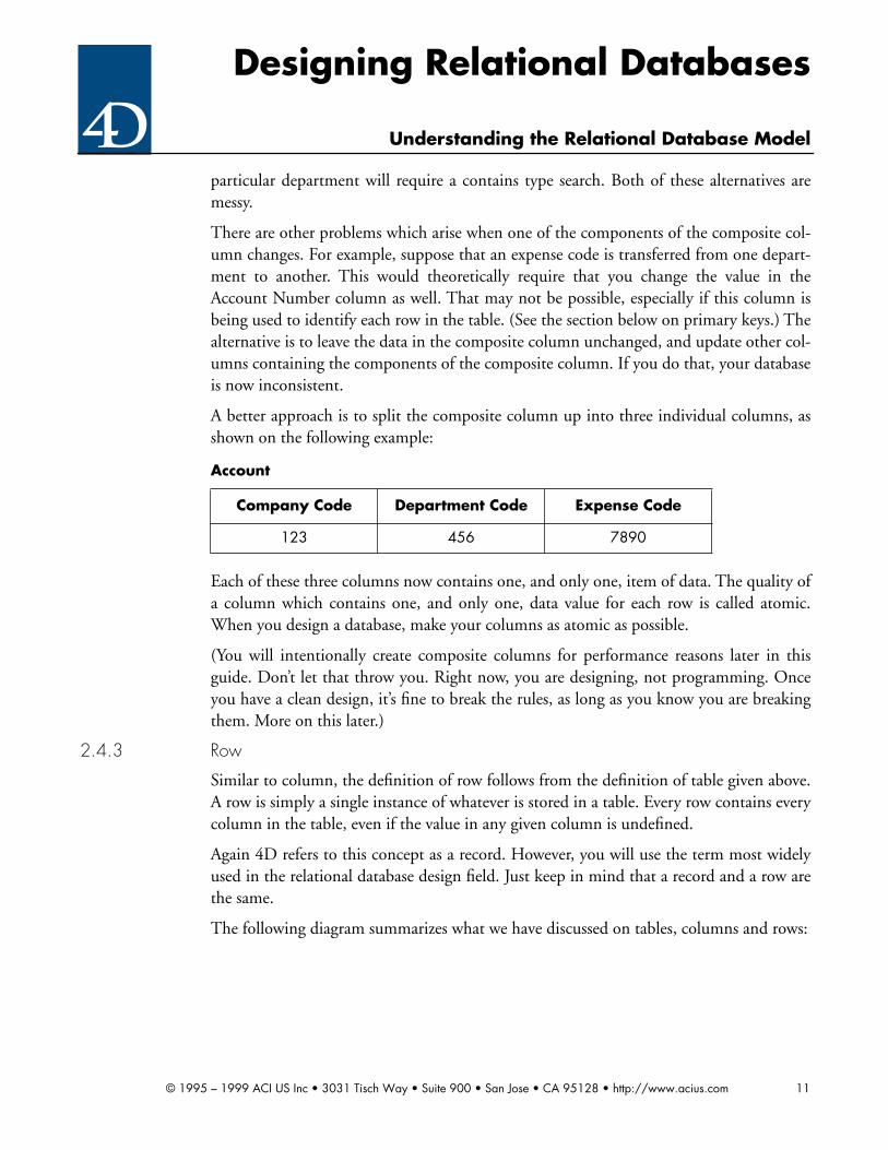
A better approach is to split the composite column up into three individual columns, asshown on the following example:
Each of these three columns now contains one, and only one, item of data. The quality ofa column which contains one, and only one, data value for each row is called atomic.When you design a database, make your columns as atomic as possible.
(You will intentionally create composite columns for performance reasons later in thisguide. Don’t let that throw you. Right now, you are designing, not programming. Onceyou have a clean design, it’s fine to break the rules, as long as you know you are breakingthem. More on this later.)
2.4.3 Row
Similar to column, the definition of row follows from the definition of table given above.A row is simply a single instance of whatever is stored in a table. Every row contains everycolumn in the table, even if the value in any given column is undefined.
Again 4D refers to this concept as a record. However, you will use the term most widelyused in the relational database design field. Just keep in mind that a record and a row arethe same.
The following diagram summarizes what we have discussed on tables, columns and rows:
Account
Company Code Department Code Expense Code
123 456 7890
© 1995 – 1999 ACI US Inc • 3031 Tisch Way • Suite 900 • San Jose • CA 95128 • http://www.acius.com 11

Designing Relational Databases
Understanding the Relational Database Model
Figure 2
2.4.4 Primary key
The concept of a primary key is basic to the relational database model. The relationaldatabase model states that every row in a table must be unique. Therefore, there must beeither a single column or a combination of columns which uniquely identifies each andevery row in the table. This column or combination of columns is referred to as the pri-mary key.
Thus the definition of a primary key is the column or combination of columns which canbe used to uniquely identify one row from any other row in the table.
Now consider three tables instead of just one:
Description Part NumberSpittoon 32Umbrella Stand 27Buggy Whip 48
Column
Row
Table
Part
Part Number Part Description
27 Umbrella Stand
32 Spittoon
48 Buggy Whip
Warehouse
Warehouse Code Warehouse City
A Buffalo
B Hong Kong
C New York
Stock
Part Number Warehouse Code Stock Quantity
27 A 10
© 1995 – 1999 ACI US Inc • 3031 Tisch Way • Suite 900 • San Jose • CA 95128 • http://www.acius.com 12

Designing Relational Databases
Understanding the Relational Database Model
The primary key of [Part] is [Part]Part Number. This column uniquely identifies each andevery row in this table. Similarly, the primary key of [Warehouse] is [Warehouse]Ware-house Code.
When we get to [Stock], the issue is not so obvious. There is not any single column whichuniquely identifies each and every row of this table.
The answer is that [Stock] has a multi-column primary key. The primary key of [Stock]consists of two columns: [Stock]Part Number and [Stock]Warehouse Code. A primarykey, like [Part]Part Number, which contains only one column is referred to as a simplekey. A primary key which contains more than one column, like the combination of[Stock]Part Number and [Stock]Warehouse Code, is referred to as a composite key.
(4D departs slightly from the relational database model by not explicitly supporting com-posite keys. Do not let that bother you for now. Right now you are designing, not pro-gramming. Go ahead and design your database using any necessary composite keys. Lateryou will show you how to handle composite keys in 4D.)
Another aspect of a primary key is permanence. Permanence indicates that the value inthe primary key will never change over the life of a row. Take as an example the followingtable:
While the combination of [Person]Last Name and [Person]First Name uniquely identifieseach row in this table, there is a problem with the permanence of these columns. Assumethat Mark Vernon and Karla Worth get married, and they decide to hyphenate their last
27 B 15
27 C 7
32 B 25
48 A 8
48 B 12
Person
Last Name First Name SSN
Williams Doris 458-38-6214
Worth Karla 155-78-1648
Vernon Mark 788-45-3546
Jones Marc 258-45-3577
Stock
© 1995 – 1999 ACI US Inc • 3031 Tisch Way • Suite 900 • San Jose • CA 95128 • http://www.acius.com 13

Designing Relational Databases
Understanding the Relational Database Model
names. Suddenly the values stored in the table become:
That might seem fine, just looking at this table alone, but what if you used these columnsto relate to other tables? (See the section below on relations.) Now all of the sudden, youhave to change all of the values stored in the related tables. But wait! That might affectother tables related to the related tables. This process can go on endlessly.
This points out another obvious fact. In a composite key, all columns must be unchang-ing. Any change to any of the columns in the primary key results in a change to the pri-mary key, and that is not allowed.
The obvious solution is to make sure that all columns in the primary key never changeduring the life of a row. Looking at the [Person] table you might choose the [Person]SSNcolumn as the primary key. (This is very common.)
But there is a problem with this approach as well. Obviously, a primary key must bedefined for every row in the table. (That is to say, it must be mandatory.) Assume thatKarla and Mark have a baby whom they name Jason. You now wish to enter a row forJason, but during the first two years of his life, Jason doesn’t have a value for [Person]SSN,leading to the following:
This is unacceptable. There is no way to uniquely identify Jason’s row. (By the way, thisalso implies that every column in a composite key must be mandatory.)
Person
Last Name First Name SSN
Williams Doris 458-38-6214
Worth-Vernon Karla 155-78-1648
Worth-Vernon Mark 788-45-3546
Jones Marc 258-45-3577
Person
Last Name First Name SSN
Williams Doris 458-38-6214
Worth-Vernon Karla 155-78-1648
Worth-Vernon Mark 788-45-3546
Jones Marc 258-45-3577
Worth-Vernon Jason
© 1995 – 1999 ACI US Inc • 3031 Tisch Way • Suite 900 • San Jose • CA 95128 • http://www.acius.com 14

Designing Relational Databases
Understanding the Relational Database Model
For this reason, you decide to create a unique column to serve as the primary key, asshown:
A primary key (like [Person]SSN if it works) which is already contained in the table, andis mandatory, permanent and uniquely identifies every row is referred to as a natural key.A primary key which you manufacture yourself (such as [Person]Person Number, asshown above) is referred to as a synthetic key.
Natural keys are rare, but they do exist. 4D contains built-in features for creating syn-thetic keys. In most cases, making your own synthetic key is the way to go.
One other thing about primary keys. All columns in a table which are not in the primarykey are called non-key columns. For example, in the above table, [Person]Last Name,[Person]First Name and [Person]SSN are non-key columns.
2.4.5 Relations
Closely related to the concept of primary key is that of a relation. Take another look at the[Stock] table:
Person
Last Name First Name SSN PersonNumber
Williams Doris 458-38-6214 1
Worth-Vernon Karla 155-78-1648 2
Worth-Vernon Mark 788-45-3546 3
Jones Marc 258-45-3577 4
Worth-Vernon Jason 5
Stock
Part Number
Warehouse Code Quantity
27 A 10
27 B 15
27 C 7
32 B 25
48 A 8
48 B 12
© 1995 – 1999 ACI US Inc • 3031 Tisch Way • Suite 900 • San Jose • CA 95128 • http://www.acius.com 15

Designing Relational Databases
Understanding the Relational Database Model
As indicated above, the combination of [Stock]Part Number and [Stock]Warehouse Codeis the primary key for this table. Now assume that you wish to see the [Part]Description ofeach part which is contained in the [Stock] table. By creating a relation you can now pro-duce the following view:
Notice that the values for Description are being pulled from the [Part] table. That is tosay, you are not redundantly storing the Description in every row in the [Stock] table. Youcan do this because the values stored in [Stock]Part Number match the values stored in[Part]Part Number. Notice, for example that the value for Umbrella Stand (Part Number27) matches in both [Stock] and [Part].
This points out several things about the relational database model:
• The relation database model states that links between tables should be performed onlyby matching data values stored in columns. In the example above, [Stock]Part Num-ber is being used to match to [Part]Part Number.
• This feature allows two tables to be related. A relation is simply the link between twotables both of which contain matching data in columns. (In this guide, we will use theterms related, relation and relationship interchangeably. They all refer to a linkbetween two tables as described in this section.)
• A relation is two-way. You should be able to navigate to the matching row or rows ofeither table from a row of the other table. For example, you should be able to get the[Part] row for any given [Stock] row, and you should be able to get the matching[Stock] rows for any given [Part] row.
• Relations come in three flavors: many-to-many, one-to-many or one-to-one.
• A one-to-many relation is shown like this: 1:M.
• A many-to-many relation is shown like this: M:M.
• A one-to-one relation is shown like this: 1:1.
Stock/Part Description View
Part Number
Description from Part
Warehouse Code Quantity
27 Umbrella Stand A 10
27 Umbrella Stand B 15
27 Umbrella Stand C 7
32 Spittoon B 25
48 Buggy Whip A 8
48 Buggy Whip B 12
© 1995 – 1999 ACI US Inc • 3031 Tisch Way • Suite 900 • San Jose • CA 95128 • http://www.acius.com 16

Designing Relational Databases
Understanding the Relational Database Model
• A table on the one side of a 1:M relation is called the one table. A table on the manyside of a 1:M relation is called the many table.
M:M relations can be shown during the design phase, but a M:M relation must eventu-ally be resolved into two 1:M relations using a third linking table. (More on this later.)
A foreign key is a column or set of columns which is being used to match values in a rela-tion and is not the primary key of its table. In a correctly designed database, a foreign keywill always be on the many side of a 1:M relation. Also, the matching set of columns ofthe one table will always be the primary key of the one table. If either of these statementsis not true, your design is wrong.
Look again at our example using the [Stock] table. The relation between the [Part] tableand the [Stock] table is 1:M. That is to say, that a part can be in stock in more than onewarehouse, but a [Stock] row can only refer to one part. In this situation, the matchingcolumn of the many table, i.e. [Stock]Part Number, is the foreign key of the relation.
Notice that the matching column of the one table, i.e. [Part]Part Number, is the primarykey of [Part]. The reason why the matching set of columns on the one side of a 1:M rela-tion is always the primary key of the one table is simple: The primary key is the only wayto reliably identify the desired row in the one table. By definition, a primary key is guar-anteed to be permanent, mandatory and unique. This means that the primary key isalways the best way to identify a row in a table.
Also, notice that [Stock]Part Number is not the primary key of [Stock]. (While Stock]PartNumber participates in the primary key of [Stock], it is not by itself the primary key of[Stock].)
If the matching column or set of columns of both tables in a relation are the primary keyof their respective tables, the result is a 1:1 relation. The following example illustrates this:
Person I
Last Name First Name SSN Person Number
Williams Doris 458-38-6214 1
Worth-Vernon Karla 155-78-1648 2
Worth-Vernon Mark 788-45-3546 3
Jones Marc 258-45-3577 4
© 1995 – 1999 ACI US Inc • 3031 Tisch Way • Suite 900 • San Jose • CA 95128 • http://www.acius.com 17

Designing Relational Databases
Understanding the Relational Database Model
Here [Person 1] and [Person 2] are related on the Person Number column. This column isalso the primary key for both of these tables. Since the values in both tables for PersonNumber must be unique, the result is a 1:1 relation. (That is to say, only one row can existon either side of the relation.)
1:1 relations are not common, but they do occur. When you get into physical creation ofa database, you will see that there are valid performance reasons for creating 1:1 relations.In addition, there are valid reasons when designing a database to create 1:1 relations.
2.4.6 Review• The concepts covered in this section are absolutely critical to your complete under-
standing of relational database theory. Why don’t you go over them again, and thinkabout these concepts for a minute or two?
• The relational database model is based upon all data being stored in tables.
• A table is a two dimensional collection of data. Tables are non-positional. The col-umns and rows can be rearranged without changing the table. A table is the same con-cept as a table in 4D.
• A column is a single item of data which is contained in all of the rows in the table.Ideally, a column should contain one, and only one, item of data (atomicity). Forexample, if the table stores data about persons, Last Name would be a good column inthe table. A column is the same concept as a field in 4D.
• A row is a single instance of whatever is stored in the table. For example if the tablestores data about persons, then a row refers to one person. A row is the same conceptas a record in 4D.
• Every table must have a primary key. A primary key is a column or set of columnswhich uniquely identifies every row in the table.
• All columns in the primary key must be mandatory. That is, they must all be definedfor every row in the table.
Person 2
Address City State Person Number
5456 McClintock Arlington TX 1
879 Sobrato Campbell CA 2
22358 Endres Orlando FL 3
4189 Santa Ana Cocamo IN 4
© 1995 – 1999 ACI US Inc • 3031 Tisch Way • Suite 900 • San Jose • CA 95128 • http://www.acius.com 18

Designing Relational Databases
Understanding the Relational Database Model
• In addition, all columns in the primary key must be permanent. That means, theymust all be unchanging during the life of a row in the table.
• The columns in a table which are not part of the primary key are called non-key col-umns.
• Relations are links between tables based upon matching data values in columns.
• A relation is based upon a column or set of columns which contain identical values inthe two related tables.
• Relations can be many-to-many (M:M), one-to-many (1:M), or one-to-one (1:1).
• Eventually, a M:M relation must be resolved into two 1:M relations.
• The matching set of columns of the many table in a 1:M relation is a called foreignkey.
• The matching key of the one table in 1:M relation is always (in a correctly designeddatabase) the primary key of the one table.
A relation in which both matching keys are the primary key of their respective table is a 1:1relation.
Exercises: Identifying tables, columns and keys
Exercise 2.2
Assume that data is stored on disk using the following data structure (Note: this is the waythe data is stored, not just a report.).
Part
Part Number Part Description Warehouse Code Quantity
27 Umbrella Stand
A 10
B 15
C 7
32 Spittoon
B 25
48 Buggy Whip
A 8
B 12
© 1995 – 1999 ACI US Inc • 3031 Tisch Way • Suite 900 • San Jose • CA 95128 • http://www.acius.com 19

Designing Relational Databases
Understanding the Relational Database Model
Is this a table in the relational sense? (Hint: is this structure two-dimensional?)
How would you design a search for all parts stored in warehouse B? Would it be easy?
Sort the parts by total quantity stored. Can you do this easily?
Is this structure efficient in terms of storage space?
Exercise 2.3
Consider the following tables:
Identify the primary keys of both tables.
• Are there any natural keys?
• Are there any synthetic keys?
• Are the tables related?
• If so, what is the nature of the relation (1:M, 1:1, or M:M)?
• What is the one table?
• What is the many table?
Item
Item Number Item Description Price
123 Pontoon Cover $100.00
124 Potato Peeler $5.00
125 Pimento Polisher $55.00
126 Pig Preener $25.00
127 Pain Preventer $7.50
128 Pretty Parrot $87.50
Order
Order Number Item Number Quantity
1234 123 1
1235 126 12
1236 128 7
1237 124 65
1238 123 2
1239 128 3
© 1995 – 1999 ACI US Inc • 3031 Tisch Way • Suite 900 • San Jose • CA 95128 • http://www.acius.com 20
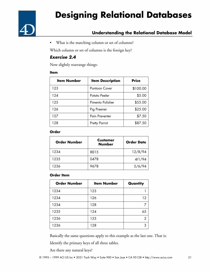
Designing Relational Databases
Understanding the Relational Database Model
• What is the matching column or set of columns?
Which column or set of columns is the foreign key?
Exercise 2.4
Now slightly rearrange things:
Basically the same questions apply to this example as the last one. That is:
Identify the primary keys of all three tables.
Are there any natural keys?
Item
Item Number Item Description Price
123 Pontoon Cover $100.00
124 Potato Peeler $5.00
125 Pimento Polisher $55.00
126 Pig Preener $25.00
127 Pain Preventer $7.50
128 Pretty Parrot $87.50
Order
Order Number Customer Number Order Date
1234 8015 12/8/94
1235 0478 4/1/94
1236 9678 5/6/94
Order Item
Order Number Item Number Quantity
1234 123 1
1234 126 12
1234 128 7
1235 124 65
1236 123 2
1236 128 3
© 1995 – 1999 ACI US Inc • 3031 Tisch Way • Suite 900 • San Jose • CA 95128 • http://www.acius.com 21

Designing Relational Databases
Understanding the Relational Database Model
• Are there any synthetic keys?
• Are any of the tables related?
• If so, describe the nature of each relation (1:M, 1:1, or M:M).
• What is the one table in each relation?
• What is the many table in each relation?
• What is the matching key in each relation?
• Which table is the many table, if any, in each relation?
• Which key is the foreign key in each relation?
Exercise 2.5
Consider the following table:
➔ What problems exist with this table structure? (Hint: look for composite columns.)
➔ Try to find the person rows where the last name is greater than “K”. Can you do this?
➔ Try to sort by the person’s last name. Can you do this?
➔ Try to search for all rows where the person lives in the state of Texas. Is this possible?
Try to sort the rows by zip code. Can you do this at all?
Person
Name SSN Address City/State/Zip
Doris Williams 458-38-6214 5456 McClintock Arlington, TX 75012
Karla Worth 155-78-1648 879 Sobrato Campbell, CA 95008
Mark Vernon 788-45-3546 22358 Endres Orlando, FL 14033
Marc Jones 258-45-3577 4189 Santa Ana Cocamo, IN 35701
© 1995 – 1999 ACI US Inc • 3031 Tisch Way • Suite 900 • San Jose • CA 95128 • http://www.acius.com 22

Designing Relational Databases
What is a relational database good for?
3 What is a relational database good for?
There will be times when you will be offered the opportunity to do a system, and you willnot be sure whether 4D is the right tool for the job. The purpose of this section is to helpyou answer that question.
• As you have seen, 4D is a relational database management system. Generally, systemswhich can be created in a relational database management system can be created in4D. (There are issues concerning performance and capacity which are beyond thescope of this guide. However, with 4D’s increasing capabilities, the vast majority ofrelational database applications being written today could be written in 4D.) Thus,you can focus on what types of systems can (or should) be created in a relational data-base management system. To do this, you will use the old three rules of thumb:
• Rows are cheap
• Columns are expensive
• Tables are priceless
What this means is simple. It is easy to add rows to tables. On the other hand, adding col-umns to a table is a fairly major undertaking. And adding entirely new tables is the equiv-alent of heart surgery.
Thus, the structure of the proposed system must be capable of being described thoroughlyand completely. (Teaching you how to describe the structure is what this guide is allabout.)
In addition, you must be able to completely describe the data structure in terms of rela-tional tables. In order for the structure to be described, it has to be stable (i.e. unchang-ing) over time. If any part of the data structure is likely to change frequently during thecourse of the system (i.e. at runtime), the system probably cannot be created with a rela-tional database alone. The quality of any part of a data structure which changes frequentlyis called volatile. There may be parts of a data structure which can be described, and partswhich cannot. (Thus, there may be stable parts of the data structure, and volatile parts.)
Don’t talk yourself out of a job here. Notice we said the job cannot be done with a rela-tional database alone. If may be needed is a spreadsheet or a word processor to store thevolatile data, that can be accomplished with 4D Calc or 4D Write.
• Here is an example a system that could not be accomplished by means of a relationaldatabase alone:
• The client is a large integrated oil company wishes to build a system to do long-termfinancial planning on the company’s projects. A project is a distinct unit of work (e.g.drilling a set of wells, etc.) with a fixed life. The performance of a project is modeled
© 1995 – 1999 ACI US Inc • 3031 Tisch Way • Suite 900 • San Jose • CA 95128 • http://www.acius.com 23

Designing Relational Databases
What is a relational database good for?
in financial variables which are displayed over a period of years. Operators are appliedto financial variables to calculate other financial variables. Eventually, this modelswhat the real-world behavior of the project would be, assuming conditions are similarto what is stored in the financial variables.
• The client cannot tell you what financial variables will be used at any given time,because they are constantly updating their financial planning methodology and add-ing new financial variables. In addition, the financial variables and their operators areconstantly changing because the client likes to do “what if ” analysis on the projects tosee what the results would be in any given situation.
Further, the client cannot tell you what period of years will be applied to a particularproject, since the life of each project is different from any other project.
Most of what is being described here is, of course, a spreadsheet. However, there is a partof the system (i.e. the concept of a project) which is quite stable. A project table could, forexample, contain the name of the project, its region, the personnel responsible for plan-ning the project, etc.
It is when you get to the financial variables that you get into trouble. One alternativewould be create an very wide table with the number of columns equal to the maximumnumber of years the client thinks he or she is likely to need, as shown below:
This approach will result in terrible performance and lots of wasted space. In addition,you will have to figure out how to store the operators and apply them to each financialvariable in each year. Since the client can use any operator on any financial variable, yourcode will have to be very complex. And since the client will constantly be coming up withnew rules, you will have a maintenance nightmare.
While you may find this example to be ridiculous, it was seriously proposed in the halls ofa major publicly-traded oil company not too long ago.
The solution did, in fact, end up using a relational database for storage, but not in theway shown above. Instead, the financial variables were stored in 4D Calc spreadsheets,and these spreadsheets were stored in rows in a table, using 4D’s built-in BLOB feature.
Financial Variable
Name Year 1 Year ... Year N
Year 1995 1996 ... NNNN
Capital Investment $1,000,000 $500,000 ... $0
Operating Expense $0 $10,000 ... $300,000
Salvage Expense $0 $0 ... $250,000
© 1995 – 1999 ACI US Inc • 3031 Tisch Way • Suite 900 • San Jose • CA 95128 • http://www.acius.com 24
Designing Relational Databases
What is a relational database good for?
By having spreadsheets explicitly associated with their various projects and making themreadily available in a multi-user relational database system, the client achieved significantperformance gains in its financial planning department. Thus, the system was successful.It would not have been successful if the only tool used was the relational database man-agement system.
There is a saying: “If the only tool you have is a hammer, pretty soon every problembegins to look like a nail.” There are some things relational databases are not good for. Getthe right tool for the job. With the 4D environment, there are some additional capabili-ties beyond that of a traditional relational database management system. This makes itpossible to use 4D for storage of volatile data, as long as you remember the issuesinvolved.
© 1995 – 1999 ACI US Inc • 3031 Tisch Way • Suite 900 • San Jose • CA 95128 • http://www.acius.com 25

Designing Relational Databases
Formal representation of tables
4 Formal representation of tables
In this guide we are going to be looking at tables in a variety of ways. The first form ofrepresenting a table which you need to learn about is called the entity/attribute listing.Don’t let the terminology throw you. This is simply a listing of all the columns in thetable, showing their types, and their participation in the primary and foreign keys. Here isan example of a the entity/attribute listing of a table we have been working with in thisguide:
The column names and data types are self-explanatory. Keys requires some explanation:
• PK indicates that the column participates in the primary key. If more than one col-umn is included in the primary key (as in this case), the columns are numbered, asshown above. Otherwise, it is simply shown as PK.
FK indicates a foreign key. Foreign keys are always numbered, as shown above, even if there isonly one of them in the table (in which case it is shown as FK1, of course). If there is more thanone column in a foreign key, they are shown like this: FK1.1, FK1.2, etc.
Exercises: Drawing entity/attribute views
Exercise 4.1
Draw the entity/attribute views for the following tables:
Stock
Column Names Data Types Keys
Part Number Longint PK1 FK1
Warehouse Code String (2) PK2 FK2
Quantity Real
Item
Item Number Item Description Price
123 Pontoon Privy $100.00
124 Potato Peeler $5.00
125 Pimento Polisher $55.00
126 Pig Preener $25.00
127 Pain Preventer $7.50
128 Pretty Parrot $87.50
© 1995 – 1999 ACI US Inc • 3031 Tisch Way • Suite 900 • San Jose • CA 95128 • http://www.acius.com 26

Designing Relational Databases
Formal representation of tables
These are the same tables used in the last exercise.
➔ How does the entity/attribute listing assist you in your understanding of the tables?
If the tables were more complex, would the tables be capable of being understood any otherway?
Order
Order Number Customer Number Order Date
1234 8015 12/8/94
1235 0478 4/1/94
1236 9678 5/6/94
Order Item
Order Number Item Number Quantity
1234 123 1
1234 126 12
1234 128 7
1235 124 65
1236 123 2
1236 128 3
© 1995 – 1999 ACI US Inc • 3031 Tisch Way • Suite 900 • San Jose • CA 95128 • http://www.acius.com 27

Designing Relational Databases
Normalization
5 Normalization
Normalization is an important part of relational database design. It is possible to explainnormalization very concisely. However learning a definition and understanding how toapply it are two very different things. For this reason, we will provide lots of examples andexplanation in this section.
5.1 What is normalization?
Normalization is the process of deciding what columns belong in what tables. One of thebasic principles of normalization to that you want to minimize redundant or duplicateddata. Another basic concept is that you want to group related columns together in a tablebecause there is a clear and logical relationship among them. Source: Reference 2
The result of normalization is a logical database design. That is, normalization results in adesign which clearly and consistently captures the true nature of the data.
The result of the normalization process is called a normal form. Normalization is a step-by-step process in which various normal forms are achieved. Thus, there is the first nor-mal form, the second normal form, and so forth. Each normal form is more logically cor-rect than the one before it. Each normal form also includes the ones before it. Thus, atable which is in second normal form is also in first normal form, and so on.
The rules of normalization are based upon common sense. It is very possible that youwould intuitively follow them. The advantage of having the rules of normalization statedexplicitly is that you can then consciously make sure that you follow all of them.
Some will certainly argue that a normalized database design is not the most optimized.We will say it again. Remember, you are designing, not programming. Once you have cre-ated a correct, normalized design you will address the performance issues and makeappropriate adjustments in your design to meet those issues. The process of backing off ofa perfectly normalized structure for performance reasons is called denormalization, andyou will be doing lots of that on the third day.
5.2 Why normalize?
There are many reasons to normalize. Here are a few of them:
• A normalized database design organizes data according to its meaning.
• A normalized database design will be robust and will not be susceptible to a variety ofproblems. Also, a normalized database design will be easy to change if modificationsbecome necessary. This is because normalization reduces redundancy or duplicationof data.
The process of normalization forces the designer to fully understand each element of the
© 1995 – 1999 ACI US Inc • 3031 Tisch Way • Suite 900 • San Jose • CA 95128 • http://www.acius.com 28

Designing Relational Databases
Normalization
data. This last benefit may be the most important.
5.3 Functional dependency
Key to understanding normalization is understanding the concept of functional depen-dency. This is a subtle concept. We say that Column A is functionally dependent on Col-umn B if, and only if, there must be a single value in Column B for every value inColumn A.
Source: Reference 2
A practical example will help. Suppose you have a database which tracks the stock market.That database contains a table called [Common Stock]. Included in the [Common Stock]table are the columns Name and Price, as follows:
Now you can say that Price is functionally dependent upon Name because there must beone, and only one, value for Price for any given Name. By the way, the process works theother way, as well. Thus Name is not functionally dependent upon Price because theredoes not have to be a single value of Name for any given Price.
• A functional dependency is written this way:
Name –> Price
This says that Price is functionally dependent on Name. Notice that it is perfectly legiti-mate to say that a column is functionally dependent upon a set of columns. Borrow froman example used earlier:
Common Stock
Name Price
Ford 25 3/8
GM 44 1/4
Chrysler 64 5/8
IBM 100 3/4
Apple 54 7/8
Microsoft 102 5/8
Stock
Part Number Warehouse Code Quantity
27 A 10
27 B 15
© 1995 – 1999 ACI US Inc • 3031 Tisch Way • Suite 900 • San Jose • CA 95128 • http://www.acius.com 29

Designing Relational Databases
Normalization
The Quantity column is functionally dependent upon the combination of the columnsPart Number and Warehouse Code.
• This functional dependency is written this way:
Part Number + Warehouse Code –> Quantity
Notice that these two columns also happen to be the primary key of this table, a broad hint as towhere you are headed next.
Exercises: Recognizing Functional Dependencies
Exercise 5.1
Consider the following tables used by a pet store database:
27 C 7
32 B 25
48 A 8
48 B 12
Inventory
Inventory Number Species Breed Acquired
2002 Canine Bulldog 1/30/95
2003 Canine Fox Terrier 2/4/95
2004 Canine Spaniel 2/14/95
2005 Feline Persian 2/17/95
2006 Feline Manx 3/2/95
2007 Feline Persian 3/14/95
2008 Canine Spaniel 3/19/95
2009 Feline Siamese 5/2/95
Feeding Plan
Breed Species Feed Quantity
Bulldog Canine Bulemia Dog Chow 16 Oz.
Fox Terrier Canine Bulemia Dog Chow 24 Oz.
Spaniel Canine Bulemia Cat Chow 18 Oz.
Stock
© 1995 – 1999 ACI US Inc • 3031 Tisch Way • Suite 900 • San Jose • CA 95128 • http://www.acius.com 30

Designing Relational Databases
Normalization
➔ Identify all functional dependencies.
➔ What columns are dependent upon a single column?
➔ What columns are dependent upon more than one column?
5.4 First Normal Form
The first normal form is easy. It is also a bit different from all of the other normal forms.It simply requires that any table that you design conform to the correct definition of atable.
Suppose you want to track employees and the projects they are currently working on, soyou create a table which looks like this:
This type of structure is common in flat file databases. It is also the reason why relationaldatabases work much better than flat file databases. The technical definition for the groupof columns representing the project name, start date and end date is a repeating group.
Siamese Feline Bulemia Cat Chow 10 Oz.
Persian Feline Bulemia Dog Chow 14 Oz.
Manx Feline Bulemia Cat Chow 10 Oz.
Feeding Plan
Employee
Column Names Data Types Keys
Employee Number Longint PK
Last Name String (45)
First Name String (45)
Project Name 1 String (20)
Start Date 1 Date
End Date 1 Date
Project Name 2 String (20)
Start Date 2 Date
End Date 2 Date
Project Name 3 String (20)
Start Date 3 Date
End Date 3 Date
© 1995 – 1999 ACI US Inc • 3031 Tisch Way • Suite 900 • San Jose • CA 95128 • http://www.acius.com 31

Designing Relational Databases
Normalization
Flat files use lots of repeating groups for the simple reason that flat file databases can onlywork with one table at a time. Therefore you don’t have a choice if you use this type ofdatabase.
• Look at the effect of a repeating group structure like the one shown. First assume thatyou want to search for all of the employees who are working on the GIS project. Theonly way to do this would be to do something like the following:
[Employee]Project Name 1 = “GIS” Or
[Employee]Project Name 2 = “GIS” Or
[Employee]Project Name 3 = “GIS”
Now you realize that you have a go-getter who is working on four projects at once. All ofthe sudden you have to add another element to the repeating group. Then any code thatyou have written to support this search has to be rewritten to allow for the new column.Also, you have to redo your forms, and so on.
Repeating groups are inherently volatile. That is one reason why they are bad. A repeatinggroup is a maintenance nightmare, because it will never be big enough.
Another problem. Suppose you want to create a project report showing the employeesworking on each project. You want the listing by project.
Can you do that? Not without an enormous amount of programming. And, again, if youadd another element to the repeating group, your report is now broken and has to berewritten.
So, you see that the rule for first normal form is as follows:
A table is in first normal form if it has no repeating groups.
Source: Reference 2
(That’s really the formal definition of the first normal form.)
The first normal form is written this way: 1NF.
Exercises: First Normal Form
Exercise 5.2
Your client has asked you to design a database which will be used for tracking a doctor'spatient records. She hands you a rather typical patient record form, which she simplywants to be converted into database storage. This patient record form has the followingblanks (we have converted them to columns for you.).
© 1995 – 1999 ACI US Inc • 3031 Tisch Way • Suite 900 • San Jose • CA 95128 • http://www.acius.com 32

Designing Relational Databases
Normalization
Personnel Evaluation
Column Names Data Types Keys
Patient ID Longint PK
Patient Last Name String (45)
Patient First Name String (45)
Appointment 1 Date Date
Appointment 1 Time Time
Appointment 2 Date Date
Appointment 2 Time Time
Appointment 3 Date Date
Appointment 3 Time Time
Appointment 4 Date Date
Appointment 4 Time Time
Last Appointment Date Date
Symptom 1 String (80)
Symptom 2 String (80)
Symptom 3 String (80)
Symptom 4 String (80)
Symptom 5 String (80)
Diagnosis 1 String (80)
Diagnosis 2 String (80)
Diagnosis 3 String (80)
Diagnosis 4 String (80)
Diagnosis 5 String (80)
Measles Boolean
Measles Diagnosis Date Date
Chickenpox Boolean
Chickenpox Diagnosis Date Date
DPT Shot Boolean
© 1995 – 1999 ACI US Inc • 3031 Tisch Way • Suite 900 • San Jose • CA 95128 • http://www.acius.com 33

Designing Relational Databases
Normalization
Identify all of the repeating groups. Come up with a set of tables which are in 1NF.
➔ Now, explain to your client why her idea of automating the patient record form is abad idea, and why your normalized database design is better.
Exercise 5.3
Your financial planning manager would like to be able to chart the company’s perfor-mance on a monthly, quarterly, and annual basis. It is important to be able to track totalsales during the period, and a 1-year rolling average sales figure (monthly and quarterlyonly). Being a finance person, he is very familiar with spreadsheets. Therefore, he pro-poses the following structure.
DPT Shot Date Date
Small Pox Vaccination Boolean
Small Pox Vaccination Date Date
Flu Shot Boolean
Flu Shot Date Date
Mumps Boolean
Mumps Diagnosis Date Date
Asthma Boolean
Asthma Diagnosis Date Date
Mold Allergy Boolean
Mold Allergy Diagnosis Date Date
Monthly Data
Column Names Data Types Keys
Year Integer PK
January Total Sales Real
January Avg Sales Real
February Total Sales Real
February Avg Sales Real
March Total Sales Real
March Avg Sales Real
April Total Sales Real
Personnel Evaluation
© 1995 – 1999 ACI US Inc • 3031 Tisch Way • Suite 900 • San Jose • CA 95128 • http://www.acius.com 34

Designing Relational Databases
Normalization
April Avg Sales Real
May Total Sales Real
May Avg Sales Real
June Total Sales Real
June Avg Sales Real
July Total Sales Real
July Avg Sales Real
August Total Sales Real
August Avg Sales Real
September Total Sales Real
September Avg Sales Real
October Total Sales Real
October Avg Sales Real
November Total Sales Real
November Avg Sales Real
December Total Sales Real
December Avg Sales Real
Quarterly Data
Column Names Data Types Keys
Year Integer PK
Q1 Total Sales Real
Q1 Avg Sales Real
Q2 Total Sales Real
Q2 Avg Sales Real
Q3 Total Sales Real
Q3 Avg Sales Real
Q4 Total Sales Real
Q4 Avg Sales Real
Monthly Data
© 1995 – 1999 ACI US Inc • 3031 Tisch Way • Suite 900 • San Jose • CA 95128 • http://www.acius.com 35

Designing Relational Databases
Normalization
He thinks this is a really great data structure, and will work well. (Obviously, he hasn’tread this guide!)
Come up with a data structure which meets the 1NF, and sell him on the idea.
5.5 Second Normal Form
Second normal form involves the idea of whether or not all of the columns in the table arefunctionally dependent upon the primary key of the table. Look at some sample data:
Now, suppose that you have identified the following functional dependencies:
Employee ID –> Name
Project ID –> Project Name
Employee ID + Project ID –> Start Date
Employee ID + Project ID –> Completion Date
You stored the fact that Employee ID 123 is Harry twice. You’ve also stored the fact thatProject ID XYZ is Space Shuttle twice. If you ever need to alter either of these facts, youmust be sure to alter all occurrences. The data will be inconsistent if you do not.
Similarly, when you enter data about a new employee, you must either assign a project tothe employee or leave the project data blank. In addition, if you enter a new project, youmust leave the employee blank or assign an employee to the project.
Should you decide to delete the data regarding the only employee in a project, you willdelete the project data as well. Should you delete the data regarding the only projectassigned to an employee, you will delete the employee data as well.
Annual Data
Column Names Data Types Keys
Year Integer PK
Annual Total Sales Real
Employee ID
Employee ID Name Project
IDProject Name Start Date Completion
Date
123 Harry XYZ Space Shuttle 7/7/91 8/8/91
123 Harry ZYX Place Scuttle 8/9/91 12/24/91
231 Mary XYZ Space Shuttle 7/12/91 12/24/91
231 Mary XYX Face Shuttle 12/26/91 3/18/92
312 Larry ZYX Place Scuttle 7/27/91 3/3/92
© 1995 – 1999 ACI US Inc • 3031 Tisch Way • Suite 900 • San Jose • CA 95128 • http://www.acius.com 36
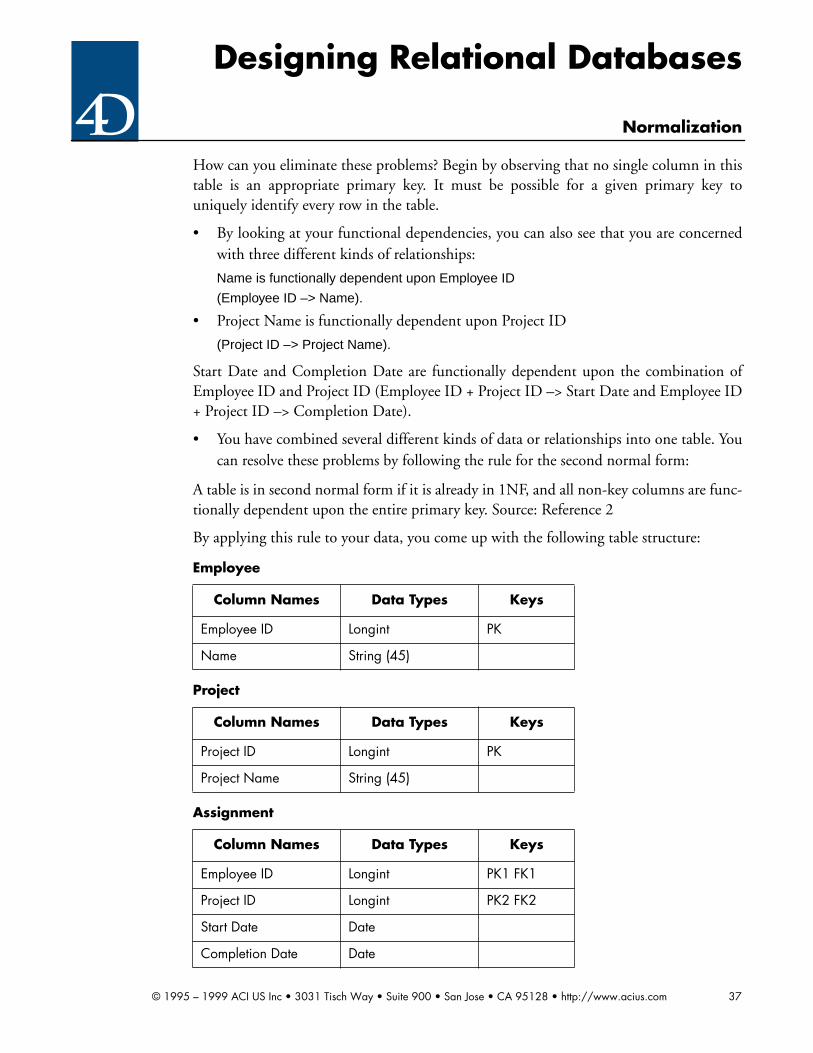
Designing Relational Databases
Normalization
How can you eliminate these problems? Begin by observing that no single column in thistable is an appropriate primary key. It must be possible for a given primary key touniquely identify every row in the table.
• By looking at your functional dependencies, you can also see that you are concernedwith three different kinds of relationships:
Name is functionally dependent upon Employee ID
(Employee ID –> Name).
• Project Name is functionally dependent upon Project ID
(Project ID –> Project Name).
Start Date and Completion Date are functionally dependent upon the combination ofEmployee ID and Project ID (Employee ID + Project ID –> Start Date and Employee ID+ Project ID –> Completion Date).
• You have combined several different kinds of data or relationships into one table. Youcan resolve these problems by following the rule for the second normal form:
A table is in second normal form if it is already in 1NF, and all non-key columns are func-tionally dependent upon the entire primary key. Source: Reference 2
By applying this rule to your data, you come up with the following table structure:
Employee
Column Names Data Types Keys
Employee ID Longint PK
Name String (45)
Project
Column Names Data Types Keys
Project ID Longint PK
Project Name String (45)
Assignment
Column Names Data Types Keys
Employee ID Longint PK1 FK1
Project ID Longint PK2 FK2
Start Date Date
Completion Date Date
© 1995 – 1999 ACI US Inc • 3031 Tisch Way • Suite 900 • San Jose • CA 95128 • http://www.acius.com 37

Designing Relational Databases
Normalization
with the following sample data:
It might appear that a redundancy has been introduced. The opposite is true. Each kindof data has been stored but once. The matching of data values is the way that the relationsare linked. The problems mentioned above have been completely eliminated.
The second normal form is written in this way: 2NF.
Exercises: Second normal form
Exercise 5.4
An insurance company has a database system which you have been asked to review. The
Employee
Employee ID Name
123 Harry
231 Mary
312 Larry
Project
Project ID Project Name
XYZ Space Shuttle
ZYX Place Scuttle
XYX Face Shuttle
Assignment
Employee ID Project ID Start Date Completion Date
123 XYZ 7/7/91 8/8/91
123 ZYX 8/9/91 12/24/91
231 XYZ 7/12/91 12/24/91
231 XYX 12/26/91 3/18/92
312 ZYX 7/27/91 3/3/92
© 1995 – 1999 ACI US Inc • 3031 Tisch Way • Suite 900 • San Jose • CA 95128 • http://www.acius.com 38

Designing Relational Databases
Normalization
main table in the system is called [Policy], and it has the following structure:
➔ Identify all functional dependencies in this table.
➔ Create a set of tables which comply with 2NF. Write the entity/attribute views forthese tables, clearly identifying all primary and foreign keys.
5.6 Third Normal Form
• The third normal form is very similar to 2NF. In fact, you probably normalized theexercise above to the third normal form without knowing it. The rule simply states:
A table is in third normal form if it is already in 2NF and no non-key column is function-ally dependent upon any other non-key column. This rule comes into play in situationslike the following:
This table is in 1NF. It does not have a composite key since Employee ID uniquely iden-tifies every row in the table. Therefore it is automatically in 2NF. (Remember that 2NFhad to do with columns being functionally dependent upon the entire primary key. Herethe primary key is one column.)
The rule for the third normal form asks for you to look for second-hand functional
Policy
Column Names Data Types Keys
Carrier ID Longint PK1 FK1
Carrier Name String (45)
Policy Number String (10) PK2
Customer ID Longint FK2
Customer Last Name String (45)
Customer First Name String (45)
Employee
Employee ID Department Building
26622 Sales West Block
41156 Accounting Headquarters
33897 R&D North Lab
88644 Sales West Block
91214 Marketing Headquarters
© 1995 – 1999 ACI US Inc • 3031 Tisch Way • Suite 900 • San Jose • CA 95128 • http://www.acius.com 39
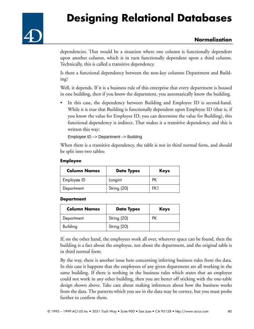
Designing Relational Databases
Normalization
dependencies. That would be a situation where one column is functionally dependentupon another column, which is in turn functionally dependent upon a third column.Technically, this is called a transitive dependency.
Is there a functional dependency between the non-key columns Department and Build-ing?
Well, it depends. If it is a business rule of this enterprise that every department is housedin one building, then if you know the department, you automatically know the building.
• In this case, the dependency between Building and Employee ID is second-hand.While it is true that Building is functionally dependent upon Employee ID (that is, ifyou know the value for Employee ID, you can determine the value for Building), thisfunctional dependency is indirect. That makes it a transitive dependency, and this iswritten this way:
Employee ID –> Department –> Building
When there is a transitive dependency, the table is not in third normal form, and shouldbe split into two tables:
If, on the other hand, the employees work all over, wherever space can be found, then thebuilding is a fact about the employee, not about the department, and the original table isin third normal form.
By the way, there is another issue here concerning inferring business rules from the data.In this case it happens that the employees of any given department are all working in thesame building. If there is nothing in the business rules which states that an employeecould not work in any other building, then you are better off sticking with the one-tabledesign shown above. Take care about making inferences about how the business worksfrom the data. The patterns which you see in the data may be correct, but you must probefurther to confirm them.
Employee
Column Names Data Types Keys
Employee ID Longint PK
Department String (20) FK1
Department
Column Names Data Types Keys
Department String (20) PK
Building String (20)
© 1995 – 1999 ACI US Inc • 3031 Tisch Way • Suite 900 • San Jose • CA 95128 • http://www.acius.com 40

Designing Relational Databases
Normalization
Take a look at another example to reinforce what you have learned already.
Consider the following table structure for an art museum:
With the following sample data:
There are no repeating groups. Therefore, the table is in 1NF.
Work ID is the only column in the primary key. Therefore, the table is in 2NF.
• When you take a look at the non-key columns, you notice that the Artist DOB isfunctionally dependent upon the combination of Artist Last Name and Artist FirstName. Thus, you have identified a transitive dependency, which you would write likethis:
Work ID –> Artist Last Name + Artist First Name –> Artist DOB
Therefore, the table is not in third normal form, and needs to be split into two tables. (Inthe structure that follows, you have also addressed the issue that there is not a natural keyfor the new table.)
Work
Column Names Data Types Keys
Work ID Longint PK
Title String (45)
Artist Last Name String (45)
Artist First Name String (45)
Artist DOB Integer
Work
Work ID Title Artist First Name
Artist Last Name
ArtistDOB
001 Snowstorm Joseph Turner 1775
002 The Night Watch Rembrandt van Rijn 1606
003 Brighton Beach John Constable 1776
004 Howl of the Weather Frederick Remington 1861
005 The Haywain John Constable 1776
Work
Column Names Data Types Keys
© 1995 – 1999 ACI US Inc • 3031 Tisch Way • Suite 900 • San Jose • CA 95128 • http://www.acius.com 41

Designing Relational Databases
Normalization
And here is the new sample data:
These tables are now in third normal form.
The third normal form is written in this way: 3NF.
Work ID Longint PK
Title String (45)
Artist ID Longint FK1
Artist
Column Names Data Types Keys
Artist ID Longint PK
Artist First Name String (45)
Artist Last Name String (45)
Artist DOB Integer
Work
Work ID Title Artist ID
001 Snowstorm 1001
002 The Night Watch 1002
003 Brighton Beach 1003
004 Howl of the Weather 1004
005 The Haywain 1003
Artist
Artist ID Artist First Name Artist Last Name Artist DOB
1001 Joseph Turner 1775
1002 Rembrandt van Rijn 1606
1003 John Constable 1776
1004 Frederick Remington 1861
Work
© 1995 – 1999 ACI US Inc • 3031 Tisch Way • Suite 900 • San Jose • CA 95128 • http://www.acius.com 42

Designing Relational Databases
Normalization
Exercises: Third normal form
Exercise 5.5
Consider the following data structure:
• Is the table in 1NF?
• Is the table in 2NF?
• Is the table in 3NF? (Hint: identify all functional dependencies. Are any non-key col-umns functionally dependent upon any other non-key columns?)
• How would you correct any problems you see? Create any necessary tables, and writean entity/attribute listing on each one of them.
5.7 Further normalization
There are either five or six normal forms, depending on whose book you read. The nor-mal forms above 3NF have to do with issues which are reminiscent of the medieval debateover how many angels can dance on the head of a pin.
You are not likely to run into a situation where you need to normalize above 3NF. If youbecome proficient at normalizing to this level, you will do well.
5.8 Review
Go over what you have learned in this chapter one more time to reinforce the concepts:
• Normalization is the process of deciding what columns belong in what tables.
• The result of normalization is a logical database design which clearly and consistentlycaptures the true nature of the data.
• Normalization is based upon the concept of functional dependency, which is wherethe value in one column can be determined from the value in the other column.
• A functional dependency is written this way:
Common Stock Name –> Common Stock Price.
Employee
Column Names Data Types Keys
Employee ID Longint PK
Employee Name String (45)
Department ID String (3)
Department Name String (20)
© 1995 – 1999 ACI US Inc • 3031 Tisch Way • Suite 900 • San Jose • CA 95128 • http://www.acius.com 43

Designing Relational Databases
Normalization
• This statement says that Common Stock Price is functionally dependent upon Com-mon Stock Name.
• A table is in first normal form if it has no repeating groups. The first normal form iswritten 1NF.
• A table is in second normal form if it is already in 1NF, and all non-key columns arefunctionally dependent upon the entire primary key. The second normal form is writ-ten 2NF.
• A table is in third normal form if it is already in 2NF and no non-key column is func-tionally dependent upon any other non-key column. The third normal form is writ-ten 3NF.
Another definition of 3NF is that transitive dependencies are not allowed. A transitivedependency is one which is indirect. That is, one column is functionally dependent upona second column, which is functionally dependent upon a third column.
Exercises: Normalization
Exercise 5.6
Assume the following functional dependencies:
Bee ID –> Bee Name
Bee ID –> Hive ID (Bee resides in hive)
Hive ID –> Hive Capacity
Hive ID –> Hive Phone Number
Flower ID –> Flower Type
Flower ID –> Color
Person ID –> Person Name
Bee ID + Person ID –> Number of Stings
Bee ID + Pollination Date + Pollination Time -> Flower ID
Ignore any composite columns in this example. This makes the problem simpler.
Assume further that a bee can sting any number of people, and that a bee can pollinateany number of flowers. Similarly, a person can be stung by any number of bees, and aflower can be pollinated by any number of bees.
Is the following table normalized?
Bee
Column Names Data Types Keys
Bee ID Longint PK
Name String (20)
© 1995 – 1999 ACI US Inc • 3031 Tisch Way • Suite 900 • San Jose • CA 95128 • http://www.acius.com 44

Designing Relational Databases
Normalization
If not, which normal form is violated? Provide and explain the correct normalization.
Is the following table normalized?
If not, which normal form is violated? Provide and explain the correct normalization.
➔ Develop a complete set of normalized tables for the above scenario. Explain in detailwhy your relations are normalized.
Exercise 5.7
Identify all functional dependencies and develop a set of normalized tables for the follow-ing scenario. Draw the entity/attribute listing for each table. Explain in detail why yourdesign is normalized.
• Sheep are cared for by shepherds and live in pens. Each shepherd has a unique ID(Shepherd ID) as well as a name (Shepherd Name) and a shirt size (Shepherd Size).
• A shepherd may look after several pens. A given pen is controlled by one shepherdonly. Each pen is identified by a unique Pen ID. Each pen also has a value (Pen Value)and a capacity.
• A given sheep lives in one and only one pen. Each sheep is assigned a Sheep ID andhas a weight (Sheep Weight) and a value (Sheep Value).
Exercise 5.8
Identify all functional dependencies and develop a set of normalized tables for the follow-ing scenario. Draw the entity/attribute listing for each table. Explain in detail why yourdesign is normalized.
• Magicians are identified by IDs (Magician ID). They have names (Magician Name)and daily rates which they charge for their magic tricks (Magician Rate).
Hive ID Longint FK1
Hive Capacity Longint
Sting
Column Names Data Types Keys
Bee ID Longint PK1
Person ID Longint PK2
Number of Stings Integer
Person Name String (45)
Bee
© 1995 – 1999 ACI US Inc • 3031 Tisch Way • Suite 900 • San Jose • CA 95128 • http://www.acius.com 45

Designing Relational Databases
Normalization
• Magicians belong to Magic Clubs. A magician may belong to more than one club.And more than one magician may belong to a club.
• Each club is identified by a unique club name (Club Name). However, once in a whilea club changes its name. Each club has a mailing address (Club Address) and a phonenumber (Club Phone).
• The tricks that magicians can show are described in the master trick catalog. Eachtrick has its own unique trick ID (Trick ID), a descriptive name (Trick Name), and arating in terms of how amazing it is (Trick Amazing).
• Most magicians are capable of performing many different tricks. It is possible for sev-eral magicians to perform the same trick. Each magician has a magic trick compe-tency rating (Trick Competency) for each trick which he or she is capable ofperforming.
Exercise 5.9
Identify all functional dependencies and develop a set of normalized tables for the follow-ing scenario. Draw the entity/attribute listing for each table. Explain in detail why yourdesign is normalized.
• Horses are cared for by trainers and live in horse barns.
• Each trainer has a unique ID (Trainer ID) as well as a name (Trainer Name) and ashoe size (Trainer Size).
• A given horse lives in one and only one horse barn. Each horse is assigned a horse ID(Horse ID) and has a weight (Horse Weight) and a value (Horse Value).
• A trainer may operate several horse barns. A given horse barn is operated by but onetrainer. Each horse barn is identified by a unique horse barn identifying number(Horse Barn ID). Each horse barn also has a capacity (Horse Barn Capacity) and avalue (Horse Barn Value). A given trainer cares for all of the horses kept in any barnhe or she owns. Thus you can tell the trainer for any given horse if you know the barnthe horse lives in.
Exercise 5.10
Identify all functional dependencies and develop a set of normalized tables for the follow-ing scenario. Draw the entity/attribute listing for each table. Explain in detail why yourdesign is normalized.
• Painters are identified by unique IDs (Painter ID). They have names (Painter Name)and daily rates which they charge for their commissions (Painter Rate).
• Painters belong to clubs. A given painter may belong to more than one club. Morethan one painter can belong to any particular club. Each club is identified by a unique
© 1995 – 1999 ACI US Inc • 3031 Tisch Way • Suite 900 • San Jose • CA 95128 • http://www.acius.com 46

Designing Relational Databases
Normalization
name (Club Name). Once in a while a club changes its name. Each club has a mailingaddress (Club Address) and a phone number (Club Phone).
• The painting mediums that the painter can paint in are described in the mastermedium catalog. Each type of medium (watercolor, oil, gouache etc.) has its ownunique medium identifier (Medium ID), a descriptive name (Medium Name), and arating in terms of how skilled it is (Medium Skill).
• Most painters are capable of painting in many different types of medium. It is alsopossible for several different painters to work in the same medium. Each painter has apainter competency rating (Medium Competency) for each type of medium that heor she is capable of working in.
© 1995 – 1999 ACI US Inc • 3031 Tisch Way • Suite 900 • San Jose • CA 95128 • http://www.acius.com 47

Designing Relational Databases
Modeling the database
6 Modeling the database
In this chapter you are going to begin to produce one of the main deliverables of thedesign process: the entity/relationship diagram (“ERD”).
6.1 What is an entity/relationship diagram?
Simply stated, an entity/relationship diagram is a picture which illustrates the tableswhich are to be included in the system and the relationships among the tables. Source:Reference 2
In relational database parlance, an entity is a object about which you intend to store data.For the purposes of this guide, you are going to treat an entity as equivalent to a table.(Despite the dark warnings in some textbooks, that is generally how it ends up beingapplied.)
Similarly, a relationship is a connection or association between or among entities. For ourpurpose you are going to treat a relation and a relationship as the same thing.
Finally, in database terms, an attribute is a characteristic of interest about an entity. Forour purposes, you will treat an attribute and a column as representing basically the sameconcept.
6.2 Why diagram?
There are at least three good reasons to introduce this technique.
• It is not possible to successfully design a system without a complete understanding ofthe entities involved.
• While normalization is a useful technique, it is not always easy to identify the func-tional dependencies involved. Why, you ask, does one decide that color of part isfunctionally dependent upon part number? Isn’t it because you mentally attach bothto the idea of a real-world thing called a part? Why not recognize this and employ thetechnique formally. You find when you do so that functional dependencies becomemuch easier to see.
• Grasping the overall physical design of a database using an ERD is easier than lookingat tables in entity/attribute listings, as you will see.
6.3 Technique
Many different diagramming styles have been proposed. It is quite possible that one is asgood as the other. Our style is illustrated by the following diagram:
© 1995 – 1999 ACI US Inc • 3031 Tisch Way • Suite 900 • San Jose • CA 95128 • http://www.acius.com 48

Designing Relational Databases
Modeling the database
Figure 3
Relationships are shown as lines. A 1 indicates which end of the line is connected to theone entity, and an M indicates which end is connected to the many entity.
To document what attribute or attributes are being used for the relationship, you can dis-play the attribute name or names, as shown below:
Figure 4
However, this is really unnecessary. As indicated in Chapter 4, there is no meaningfulchoice as to what column or columns are used to create a relation. On the one side, it isthe primary key. On the many side, it is the foreign key (consisting of the same columnsas the primary key on the one side). Thus, you only show the attribute name or names inthe diagram in the rare case where there is some ambiguity.
Here is a better way to document relationships. Since relationships represent associationsbetween entities, there will almost always be possible relationship names which are verbs.In your [Customer] and [Order] situation, you could have labeled the relationship as fol-lows:
Figure 5
This statement says “Customer generates order,” which is about as simple and straightfor-ward as documentation can get.
6.4 Why entities and relationships?
Take a look at some real-world problems to illustrate this technique. Consider the follow-ing diagram illustrating the relationship between a man and a woman in marriage:
Figure 6
In the American cultural norm one man is married to one woman at a time. (Notice thatthis is not the case in all cultures.) The American cultural norm also states that a marriageinvolves individuals of the opposite sex. Suppose that you model only the two entities
Customer Order1 M
Customer Order1 M
Customer ID
Customer Order1 M
Generates
WomanMan1 1
Marries
© 1995 – 1999 ACI US Inc • 3031 Tisch Way • Suite 900 • San Jose • CA 95128 • http://www.acius.com 49

Designing Relational Databases
Modeling the database
[Man] and [Woman] on the diagram. However, you recognize that the American cultureallows serial polygamy (i.e. multiple spouses over time). Thus, you intend to track all ofthe marriages in which individuals are involved. This would lead to the following dia-gram:
Figure 7
From a physical design standpoint, you know that it is not possible to have a M:M rela-tion in a relational database. Thus, you need to split this M:M relation into two 1:M rela-tions. This is done by adding a third linking entity between the two base entities, asshown in the following diagram:
Figure 8
The first step in developing an entity relationship diagram is to identify the things that areto be stored in your database. The name of an entity will almost always be a noun. Eachentity will have some type of identifier (the primary key) plus other attributes (i.e. col-umns). The specific value of the identifier must lead us to one and only one instance theentity.
6.5 Examples
Here is the diagram for the first structure discussed in Section 5.6, illustrating the applica-tion of 3NF:
Figure 9
And here is the diagram for the second structure discussed in Section 5.6, also illustratingthe application of 3NF:
WomanManM M
Marries
Marriage
WomanMan 1 1
M MParticipates in Participates in
Employee DepartmentM 1
Works in
© 1995 – 1999 ACI US Inc • 3031 Tisch Way • Suite 900 • San Jose • CA 95128 • http://www.acius.com 50

Designing Relational Databases
Modeling the database
Figure 10
These diagrams are natural and obvious.
This is the diagram for the example used in Section 5.5 (illustrating the use of the 2NF):
Figure 11
There should be little resistance to this diagram. [Employee] and [Project] are certainlyreal world objects which you are interested in tracking. In addition, the concept of[Assignment] is natural and obvious. The relationships between these entities are clear.This is also a good example of a many to many relationship and its appropriate diagram.Note the [Assignment] table serves as the linking table between [Employee] and [Project].
6.6 Review
Review the concepts of an entity/relationship diagram before going on.
• An entity is a real-world person, place, thing or concept which the system is intendedto track. For our purposes, you are treating an entity and a table as the same concept.
• An attribute is something about an entity which you wish to store. Again, you areconsidering an attribute and a column to represent two sides of the same coin.
• A relationship is an association between or among entities. A relationship can almostalways be labeled as a verb. You consider a relationship and a relation to be equivalent.
An entity/relationship diagram is a picture of the real world things which the system isintended to track, and the relationships among them.
Exercises: Creating entity/relationship diagrams
Exercise 6.1
➔ Refer to Exercise 5.1. Create an ERD representing the structure used in that exercise.
Exercise 6.2
➔ Refer to Exercise 5.2. Create an ERD representing the normalized structure you cre-
Work ArtistM 1
Created by
Assignment
ProjectEmployee 1 1
M MWorks on Manages
© 1995 – 1999 ACI US Inc • 3031 Tisch Way • Suite 900 • San Jose • CA 95128 • http://www.acius.com 51

Designing Relational Databases
Modeling the database
ated in that exercise.
Exercise 6.3
➔ Refer to Exercise 5.4. Create an ERD representing the normalized structure you cre-ated in that exercise.
Exercise 6.5
➔ Refer to Exercise 5.6. Create an ERD representing the normalized structure you cre-ated in that exercise.
Exercise 6.6
➔ Refer to Exercise 5.7. Create an ERD representing the normalized structure you cre-ated in that exercise.
Exercise 6.7
➔ Refer to Exercise 5.8. Create an ERD representing the normalized structure you cre-ated in that exercise.
Exercise 6.8
➔ Refer to Exercise 5.9. Create an ERD representing the normalized structure you cre-ated in that exercise.
Exercise 6.9
➔ Refer to Exercise 5.10. Create an ERD representing the normalized structure you cre-ated in that exercise.
Exercise 6.10
Consider the following scenario.
This database will be used by the Central Pirate Registry located in the Lower BermudaTriangle. (No doubt the 4D system used will be unregistered pirated software!)
• Pirates are identified by unique pirate nicknames regulated by the Central Pirate Reg-istry. Pirates are never allowed to change their nicknames. In addition, each pirate isgiven a Christian name, a ferocity rating, and a date of first piracy.
• Pirate ships are also identified by unique pirate ship names. These are also regulatedby the Central Pirate Registry. Important information about a pirate ship includes thenumber of masts, number of cannon and date commissioned.
• Merchant vessels are identified by unique merchant ship names regulated by thePotential Victims Association of London, England. Important characteristics of mer-chant vessels include weight and number of masts. The Pirate Registry keeps track ofmerchant vessels that have actually been plundered or sunk.
© 1995 – 1999 ACI US Inc • 3031 Tisch Way • Suite 900 • San Jose • CA 95128 • http://www.acius.com 52

Designing Relational Databases
Modeling the database
• A given pirate is a crew member for a specific pirate ship at any given time. A piratemay also be unemployed at some times. One and only one pirate is Captain of oneand only one pirate ship at any given time. (Assume that the history of past employ-ment is not material.)
• The Pirate Registry keeps track of each incident of plundering. The record identifiesthe pirate ship, the merchant vessel, and the date of plundering, whether or not themerchant vessel was sunk, and how many innocent seamen were forced to walk theplank. It is possible for the same pirate ship to plunder the same merchant ship morethan once.
➔ Identify all functional dependencies.
➔ Develop a normalized database structure.
➔ Create a complete entity/attribute listing for all tables in the structure.
➔ Create an entity/relationship diagram for the structure.
© 1995 – 1999 ACI US Inc • 3031 Tisch Way • Suite 900 • San Jose • CA 95128 • http://www.acius.com 53

Designing Relational Databases
Discovering entities, attributes and relationships
7 Discovering entities, attributes and relationships
This chapter contains a simple cookbook approach for determining what entities,attributes and relationships are included in the system.
7.1 A client interview process
Discovering entities consists of interviewing the client and asking the question: “Whattypes of things does this system intend to track?” The answer to this question will inevita-bly consist of lots of nouns and adjectives.
Generally, the nouns will be entities and attributes and the adjectives will be (or willimply) attributes.
Looking at our example above, if you ask this question of your client, he or she mightreply: “We need to track men and women and the marriages they are involved in.” (Thisis a remarkably clear answer, and you will not normally get anything so easy as this.) Youhave three nouns in this sentence, so you can propose three candidate entities: [Man],[Woman] and [Marriage].
It is sometimes difficult to tell whether something is an entity or attribute. This can beresolved by considering the purpose of the design activity. You think of something as anentity if it is something about which you want to store data. Also, if something has anattribute, it is an entity. Attributes can’t have attributes.
Once you have finished the process of recording and analyzing the client’s response, youask the next question: “What is it about entity name that you wish to track?” Again, youwill get a statement with a lot of nouns and adjectives. Almost all of these will beattributes, but you may discover another entity or two in the process. You then need toadd this to your list of entities and go on.
Returning to your example, let us assume that you ask:
“What is it about [Man] that you wish to track?”
and the client replies:
“We need to know the man’s last name, first name, middle initial, address, city, state, zip code,age, ethnic group and religious preference.”
Again, an unrealistically clean response. Based upon that, you can make the followingentity/attribute listing for [Man]:
MAN
Column Names Data Types Keys
Man ID Longint PK
© 1995 – 1999 ACI US Inc • 3031 Tisch Way • Suite 900 • San Jose • CA 95128 • http://www.acius.com 54

Designing Relational Databases
Discovering entities, attributes and relationships
If you can’t decide whether a noun is an attribute or an entity, make it an entity. It will fallout later in the design process.
In terms of discovering the relationships, ask your client this question for every entity pairin your list:
“Is there a relationship between entity A and entity B?”
For those pairs of entities which the client answers “Yes” ask the following two questions:
“Can there be many entity As for each entity B?”
and
“Can there be many entity Bs for each entity A?”
If the answer leads to a 1:M relationship, you can model it accordingly. If the answer leadsto a M:M relationship, you know that you have a hidden entity, and you need to probefurther to determine the details of the linking entity.
Returning to your example, let us assume that you ask:
“Can there be many men for each woman?”
and the client replies:
“The American cultural norm does not allow polygamy. However, since it does allow multiplemarriages over time, I would say, yes, there can be many men for each woman.”
Then you ask:
“Can there be many women for each man?”
and the client replies:
“Again, I would say, yes, there can be many women for each man.”
Last Name String (45)
First Name String (45)
MI String (45)
Address String (80)
City String (30)
State String (2)
Zip Code String (9)
Ethnic Group String (20)
Religious Preference String (20)
MAN
© 1995 – 1999 ACI US Inc • 3031 Tisch Way • Suite 900 • San Jose • CA 95128 • http://www.acius.com 55
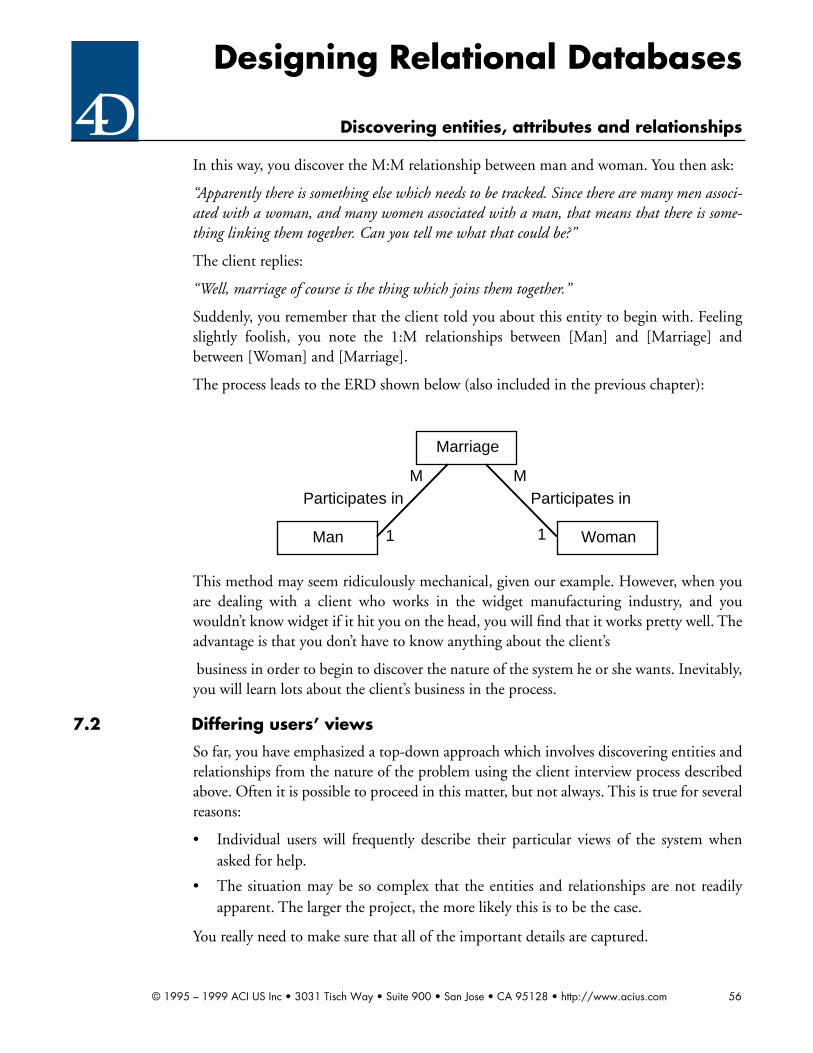
Designing Relational Databases
Discovering entities, attributes and relationships
In this way, you discover the M:M relationship between man and woman. You then ask:
“Apparently there is something else which needs to be tracked. Since there are many men associ-ated with a woman, and many women associated with a man, that means that there is some-thing linking them together. Can you tell me what that could be?”
The client replies:
“Well, marriage of course is the thing which joins them together.”
Suddenly, you remember that the client told you about this entity to begin with. Feelingslightly foolish, you note the 1:M relationships between [Man] and [Marriage] andbetween [Woman] and [Marriage].
The process leads to the ERD shown below (also included in the previous chapter):
This method may seem ridiculously mechanical, given our example. However, when youare dealing with a client who works in the widget manufacturing industry, and youwouldn’t know widget if it hit you on the head, you will find that it works pretty well. Theadvantage is that you don’t have to know anything about the client’s
business in order to begin to discover the nature of the system he or she wants. Inevitably,you will learn lots about the client’s business in the process.
7.2 Differing users’ views
So far, you have emphasized a top-down approach which involves discovering entities andrelationships from the nature of the problem using the client interview process describedabove. Often it is possible to proceed in this matter, but not always. This is true for severalreasons:
• Individual users will frequently describe their particular views of the system whenasked for help.
• The situation may be so complex that the entities and relationships are not readilyapparent. The larger the project, the more likely this is to be the case.
You really need to make sure that all of the important details are captured.
Marriage
WomanMan 1 1
M MParticipates in Participates in
© 1995 – 1999 ACI US Inc • 3031 Tisch Way • Suite 900 • San Jose • CA 95128 • http://www.acius.com 56
Designing Relational Databases
Discovering entities, attributes and relationships
• The alternative is to recognize and document the individual users’ views. These willoften be embodied in reports, paper forms, or screens of the existing system. This isoften called a bottom-up approach. Here is the procedure:
• Document each user’s view using the interview process shown above.
• List and define all data elements (entities, attributes and relationships).
• Identify all functional dependencies for each view.
• Develop an ERD for each view.
• Normalize the contents of each view.
• Examine all of the views.
• Look for entities with the same key. It should usually be possible to combine theminto one entity.
• Look for entities or relationships with attributes which are keys or parts of keys ofother relationships or entities. These will usually be foreign keys, and are indicative ofother relationships.
Be very careful to avoid duplication of entities, relationships and attributes.
The following section will point out some of these problems.
7.3 Naming conflicts
The first area of concern is naming conflicts. Here you run into synonyms and hom-onyms
Two words are synonyms when they have the same or nearly identical meaning. We usethe word in a special way. In a database, two names are synonyms if they represent thesame concept.
Two words are homonyms if they sound the same or are spelled the same but have differ-ent meanings. In a database, one word which is used for two distinct concepts is a hom-onym.
Both of these items are things to avoid in designing a database. Unfortunately, they cropup all too often.
Assume that you have a client with several personnel involved in the database design pro-cess. One individual, a Mr. Smith, is the sales and marketing guy. The other person, Ms.Jones, is the accountant.
When you interview Mr. Smith he tells us the system needs to keep track of Product SalesSlips. When you interview Ms. Jones, she says the system must keep track of PurchaseOrders.
You think you have two distinct entities here. The opposite is true. After probing, you
© 1995 – 1999 ACI US Inc • 3031 Tisch Way • Suite 900 • San Jose • CA 95128 • http://www.acius.com 57

Designing Relational Databases
Discovering entities, attributes and relationships
find that a Product Sales Slip is simply the salmon colored copy of a Purchase Order. (Theclient has re-labeled this particular copy at the request of the sales and marketing folks.)
You have just been bitten by a synonym. The result of a synonym is that you will haveextraneous entities that need to be combined.
A homonym is similar. Assume that you are developing an application for tracking per-sonnel matters. One of your entities is [Employee]. After probing, you find that there aretwo types of employees, hourly and salaried. The characteristics of these two types ofemployees are totally different. Hourly employees have different benefits, and so on.
This is an example of an is a relationship. A salaried employee is a member of the class ofemployee. Likewise, an hourly employee is a member of the class of employee. Nonethe-less, the attributes of these entities are so different that you must recognize them formally,which you do as follows:
This is an example of a 1:1 relationship. (Whether you implement this 1:1 relationship isanother matter. Remember, you are designing, not programming.)
The homonym was employee. By considering this as a single entity, you were missing a basicaspect of the system. Thus a homonym will disguise multiple entities as a single entity.
Exercises: Client interview process
Exercise 7.1
The law office of Dewey, Cheatham and Howe, Esq. has asked you to design a system forkeeping track of case information, and helping the firm to fully automate their practice ofambulance-chasing personal injury law.
Your client contact is Hugh Louis Dewey (known to his friends as Huey Louie Dewey),the senior partner of the firm. Huey is an aggressive, hotshot young lawyer, and he knowsit. Unfortunately, he thinks he knows as much about database design as you do.
One of Huey’s main objectives is to track the effectiveness of his yellow pages, print, radioand television advertising. For this reason, he wants to be able to track the clients whocome to him as the result of any particular advertisement. By doing so, Huey hopes to beable to focus his advertising dollars on the most effective advertisers and ads.
Employee
SalariedHourly 1 1
1 1Is a Is a
© 1995 – 1999 ACI US Inc • 3031 Tisch Way • Suite 900 • San Jose • CA 95128 • http://www.acius.com 58

Designing Relational Databases
Discovering entities, attributes and relationships
Also, Huey receives referrals from doctors who work with him on cases. (He refers busi-ness to them as well, a classic example of a good-old-boy, “you scratch my back and I’llscratch yours” relationship.) He wants to track which doctors are sending him the mostbusiness, so that he can return the favor.
When you arrive, you find that Huey has already designed the database structure for you.He simply wants you to implement it, and because he has saved you all this work, hewants a discount. Here is a part of his structure:
Client
Column Names Data Types Keys
Client Last Name String (45) PK1
Client First Name String (45) PK2
Client MI String (45) PK3
Client Address Text
Client CSZ String (45)
Work Phone String (10)
Home Phone String (10)
Ad Result Boolean
Advertiser Name String (30) FK1.1
Advertiser Phone String (10)
Ad Date Date FK1.2
Physician Referral Boolean
Physician Name String (80)
Physician Specialty String (20)
Case
Column Names Data Types Keys
Case Number Longint PK
Client Last Name String (45) FK1.1
Client First Name String (45) FK1.2
Work Phone String (10)
Home Phone String (10)
Defendant Name String (45)
© 1995 – 1999 ACI US Inc • 3031 Tisch Way • Suite 900 • San Jose • CA 95128 • http://www.acius.com 59

Designing Relational Databases
Discovering entities, attributes and relationships
➔ Some of these tables contain composite columns. Eliminate them and replace themwith atomic columns.
➔ Some of Huey’s choices for primary keys are suspect. Correct them. Create synthetickeys where necessary.
➔ Identify all functional dependencies.
➔ Normalize these tables to 3NF.
➔ There are some missing tables in this structure. Add them.
➔ Create an entity/attribute listing for each normalized table identifying the primaryand foreign keys.
➔ Create an ERD representing the normalized structure.
➔ You are a hungry database designer. You don’t particularly like this person, but youneed the money. On the other hand, you realize that he would just as soon sue you aslook at you. Explain to Huey why your structure will be better than his for the ongo-
Case Amount Real
Defendant Address Text
Defendant CSZ String (45)
Opposing Atty Name String (80)
Opposing Atty Phone String (10)
Ad Result Boolean
Advertiser Name String (30) FK2.1
Advertiser Phone String (10)
Ad Date Date FK2.2
Physician Referral Boolean
Physician Name String (80)
Physician Specialty String (20)
Ad
Column Names Data Types Keys
Advertiser String (30) PK1 FK1
Ad Date Date PK2
Case
© 1995 – 1999 ACI US Inc • 3031 Tisch Way • Suite 900 • San Jose • CA 95128 • http://www.acius.com 60

Designing Relational Databases
Discovering entities, attributes and relationships
ing automation of his practice.
Exercise 7.2
Your client is American Press International (“API”), a news service used by various news-papers and other media nationwide.
The name of your contact is Dave. He is the general manager of API’s New York office.You proceed to interview Dave as shown in the following dialog:
You: “Dave, can you tell me what types of things the system should keep trackof?”
Dave: “Well, we have various newspapers, magazines and other publishers. Theyfile stories. Stories are written by reporters working for these publishers.We need to know the publishers of any story, as well as the reporter whowrote the story. It’s frequently handy to know who a reporter has workedfor as well.
“Anyway, we get requests for stories having to do with particular subjects.We track subjects as single words. For example, we could have a customerwho asks for stories with the words ‘Persian,’ ‘Gulf,’ ‘War,’ ‘Desert’ or‘Storm’. Also we need to be able to ask for stories which include all of a setof subjects, or don’t include subjects, or any combination of these. So itcan get pretty complicated.
“That’s basically how it works.”
Dave now gets called away to an urgent meeting, and that’s all you have go on. Beforerunning off, Dave asks you to put together something “quick and dirty” showing himwhat you think the system would look like.
➔ Identify all of the entities to be included in the system.
➔ See if you can figure out the attributes as well. (Guess if you have to.)
➔ Identify the functional dependencies between the attributes.
➔ Create an entity/attribute listing for each entity.
➔ Try to create an ERD based upon the above.
© 1995 – 1999 ACI US Inc • 3031 Tisch Way • Suite 900 • San Jose • CA 95128 • http://www.acius.com 61
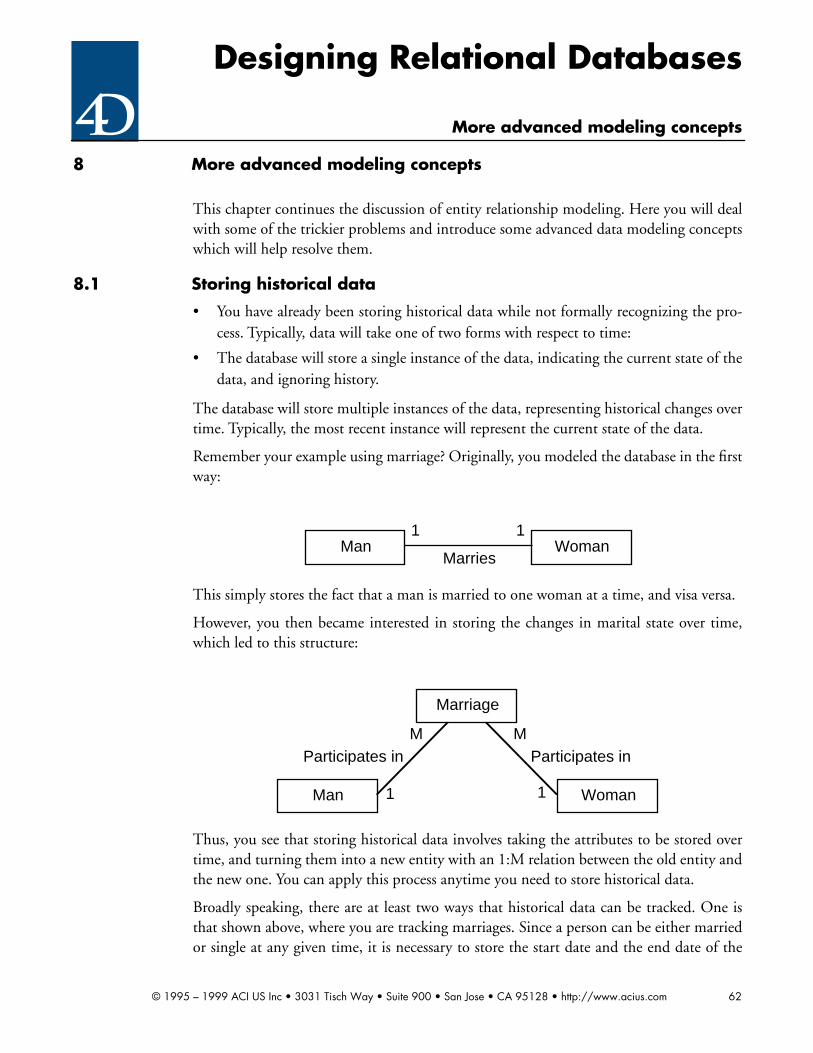
Designing Relational Databases
More advanced modeling concepts
8 More advanced modeling concepts
This chapter continues the discussion of entity relationship modeling. Here you will dealwith some of the trickier problems and introduce some advanced data modeling conceptswhich will help resolve them.
8.1 Storing historical data
• You have already been storing historical data while not formally recognizing the pro-cess. Typically, data will take one of two forms with respect to time:
• The database will store a single instance of the data, indicating the current state of thedata, and ignoring history.
The database will store multiple instances of the data, representing historical changes overtime. Typically, the most recent instance will represent the current state of the data.
Remember your example using marriage? Originally, you modeled the database in the firstway:
This simply stores the fact that a man is married to one woman at a time, and visa versa.
However, you then became interested in storing the changes in marital state over time,which led to this structure:
Thus, you see that storing historical data involves taking the attributes to be stored overtime, and turning them into a new entity with an 1:M relation between the old entity andthe new one. You can apply this process anytime you need to store historical data.
Broadly speaking, there are at least two ways that historical data can be tracked. One isthat shown above, where you are tracking marriages. Since a person can be either marriedor single at any given time, it is necessary to store the start date and the end date of the
WomanMan1 1
Marries
Marriage
WomanMan 1 1
M MParticipates in Participates in
© 1995 – 1999 ACI US Inc • 3031 Tisch Way • Suite 900 • San Jose • CA 95128 • http://www.acius.com 62

Designing Relational Databases
More advanced modeling concepts
event, as shown in the following entity/attribute listing:
Notice that it is necessary to include Date Married in the primary key, since two peoplecan be married more than once.
The other way is best illustrated by an example you used earlier of [Parts]. Assume thatyou want to track the changes in the price of any given part. Obviously, a part always hasa price. Thus, it is not necessary to store the end date of a price. You simply infer that theend date of one price is equal to the start date of the next price. This leads the followingstructure:
Again, you must include Start Date in the primary key, since a part can have the sameprice more than once.
8.2 Relating an entity to itself (bill of materials)
Another classic problem of relational design is called the bill of materials problem. Thisconcerns the situation where a part is included in an assembly, which is also itself a part.This is known as a recursive relationship. The relationship is recursive because it loopsback upon itself.
You know you have a recursive relationship if an entity relates to instances of itself. Theexample of a bill of materials is apt because a part can include a part.
Marriage
Column Names Data Types Keys
Man ID Longint PK1 FK1
Woman ID Longint PK2 FK2
Date Married Date PK3
Date Divorced Date
Part Price
Column Names Data Types Keys
Part ID Longint PK1
Start Date Date PK2
Price Real
© 1995 – 1999 ACI US Inc • 3031 Tisch Way • Suite 900 • San Jose • CA 95128 • http://www.acius.com 63

Designing Relational Databases
More advanced modeling concepts
The structure to implement this relationship is typically something like the following:
Notice that the relationship goes full circle. That is the mark of a recursive relationship.Also notice that the relationship is 1:M on one side and 1:1 on the other. Thus, a part canbe a component of many assemblies, but an assembly is a part.
There is a problem with this approach which cannot be solved with relational databasedesign. Take a look at the following sample data:
Part
Column Names Data Types Keys
Part ID Longint PK
Description String (80)
Component Assembly
Column Names Data Types Keys
Component ID Longint PK1
Assembly ID Longint PK2
Component Assembly
Component ID Assembly ID
123 456
123 567
123 678
456 777
456 778
567 887
ComponentAssembly
Part
Assembly IDComponent ID
11
1M
© 1995 – 1999 ACI US Inc • 3031 Tisch Way • Suite 900 • San Jose • CA 95128 • http://www.acius.com 64
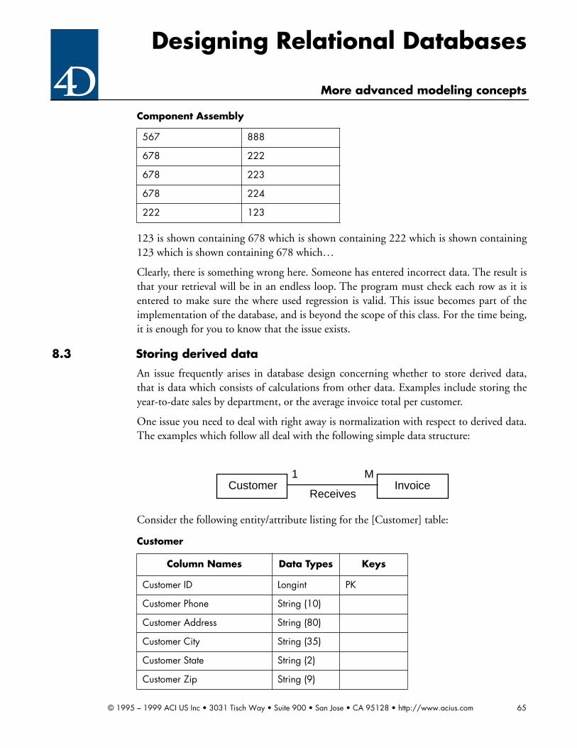
Designing Relational Databases
More advanced modeling concepts
123 is shown containing 678 which is shown containing 222 which is shown containing123 which is shown containing 678 which…
Clearly, there is something wrong here. Someone has entered incorrect data. The result isthat your retrieval will be in an endless loop. The program must check each row as it isentered to make sure the where used regression is valid. This issue becomes part of theimplementation of the database, and is beyond the scope of this class. For the time being,it is enough for you to know that the issue exists.
8.3 Storing derived data
An issue frequently arises in database design concerning whether to store derived data,that is data which consists of calculations from other data. Examples include storing theyear-to-date sales by department, or the average invoice total per customer.
One issue you need to deal with right away is normalization with respect to derived data.The examples which follow all deal with the following simple data structure:
Consider the following entity/attribute listing for the [Customer] table:
567 888
678 222
678 223
678 224
222 123
Component Assembly
Customer
Column Names Data Types Keys
Customer ID Longint PK
Customer Phone String (10)
Customer Address String (80)
Customer City String (35)
Customer State String (2)
Customer Zip String (9)
InvoiceCustomer1 M
Receives
© 1995 – 1999 ACI US Inc • 3031 Tisch Way • Suite 900 • San Jose • CA 95128 • http://www.acius.com 65

Designing Relational Databases
More advanced modeling concepts
You define the Average Invoice Amount as the average of all Invoice Totals for a customer.Thus, if you knew all of the Invoice Totals for a customer, you could calculate the AverageInvoice Amount. You would then argue that Average Invoice Amount is functionallydependent upon Invoice Number, not Customer ID. The opposite is true. Remember thedefinition of functional dependency from Chapter 5:
You say that Column A is functionally dependent on Column B if, and only if, there mustbe a single value in Column B for every value in Column A. Source: Reference 2
Now, there is not a single value of Average Invoice Amount for every value in InvoiceNumber. In fact, you know that this is not true. Thus, Average Invoice Amount is notfunctionally dependent upon Invoice Number. And you can further conclude that thiscolumn is not a violation of the any normal forms that you have seen.
However, lets take another example. Consider the following entity/attribute listing:
Here you are storing Invoice Grand Total which consists of the sum of Invoice Total andInvoice Tax. Since Invoice Grand Total is functionally dependent upon the combinationof Invoice Total and Invoice Tax, this violates 3NF.
There is a third possibility. Look at one more scenario. This time you will include boththe [Customer] and [Invoice] tables:
Average Invoice Amount Real
Invoice
Column Names Data Types Keys
Invoice Number Longint PK
Customer ID Longint FK1
Invoice Total Real
Invoice Tax Real
Invoice Grand Total Real
Customer
Column Names Data Types Keys
Customer ID Longint PK
Customer Phone String (10)
Customer Address String (80)
Customer
© 1995 – 1999 ACI US Inc • 3031 Tisch Way • Suite 900 • San Jose • CA 95128 • http://www.acius.com 66

Designing Relational Databases
More advanced modeling concepts
Notice that [Invoice]Discount Amount is a calculated column, consisting of[Invoice]Invoice Gross Total multiplied by [Customer]Discount Rate. Since the[Invoice]Discount Amount is clearly functionally dependent upon the combination of[Invoice]Invoice Gross Total and [Customer]Discount Rate 3NF is obviously violated.
Thus, there are three types of derived data. The first type is summary derived data whichis calculated with respect to a one table by calculating values from a many table. In ourfirst example, the Average Invoice Amount is summary derived data because the [Cus-tomer] table is the one table in a 1:M relationship with [Invoice].
The second type is detail derived data which is calculated from the columns within a sin-gle table and stored in that table. In your second example, the Invoice Grand Total isdetail derived data.
The third type is cross-table derived data which is calculated from columns of both tables,but stored on the many side of a 1:M relationship. In your third example, [Invoice]Dis-count Amount is an example of cross-table derived data. ([Invoice]Invoice Net Total isdetail derived data, since it is calculated from columns entirely within the [Invoice] table.)
There is only one type of derived data which is normalized. That is summary deriveddata, or data which is calculated from the columns in a many table and stored in a columnin the one table. Modeling of derived data other than summary derived data should beavoided. (However, you may end up storing other types of derived data anyway. Remem-ber, you are designing, not programming.)
Even with respect to summary derived data, there is an issue of redundancy. Since the
Customer City String (35)
Customer State String (2)
Customer Zip String (9)
Discount Rate Real
Invoice
Column Names Data Types Keys
Invoice Number Longint PK
Customer ID Longint FK1
Invoice Gross Total Real
Discount Amount Real
Invoice Net Total Real
Customer
© 1995 – 1999 ACI US Inc • 3031 Tisch Way • Suite 900 • San Jose • CA 95128 • http://www.acius.com 67

Designing Relational Databases
More advanced modeling concepts
derived data is calculated from other data, the data is in a sense redundant. You could cal-culate it anytime you like, and this makes storage of this data unnecessary. However,clearly this is not a major issue. Since the data is being stored on the one side of the 1:Mrelationship, by definition summary derived data will take up much less space than eitherof the other types of derived data.
In addition, you must always recalculate the data whenever any of the underlying datachanges, which creates a relational integrity issue. Isn’t this what normalization is designedto avoid? This is a serious issue, but is somewhat mitigated by the mechanism of posting,which is explained below.
Finally, there is an issue concerning performance. Returning to your original example:
Now assume that you add an invoice for a given customer. Calculating Average InvoiceAmount is going to require that you perform the following steps:
• Enter the invoice as you normally would.
• Select all of the invoices ever created for this customer, including the new one.
• Add up all of [Invoice]Invoice Totals for all of the invoices returned in the previousstep.
• Divide the resulting sum by the number of invoices ever created for this customer,including the new one.
Save the result into the [Customer]Average Invoice Amount column.
That’s certainly a lot of trouble just to enter a single invoice. The process is going to beslow. Worse, for your best customers, the ones with the most invoices, it is going tobecome continuously slower.
In order to eliminate or reduce the issues of relational integrity and performance, judg-ment must be applied to the problem of storing derived data. In order to understand how
Customer
Column Names Data Types Keys
Customer ID Longint PK
Customer Phone String (10)
Customer Address String (80)
Customer City String (35)
Customer State String (2)
Customer Zip String (9)
Average Invoice Amount Real
© 1995 – 1999 ACI US Inc • 3031 Tisch Way • Suite 900 • San Jose • CA 95128 • http://www.acius.com 68

Designing Relational Databases
More advanced modeling concepts
to apply this judgment, you must further categorize the derived data. Consider the fol-lowing alternate design of the [Customer] table:
Here, you have split the Average Invoice Amount column into two columns, Total Pur-chases and Total Number of Invoices. Note that these are the components of the AverageInvoice Amount using the calculation process detailed above. What you have done is tosplit up Average Invoice Amount into its component parts. You are not going to storeAverage Invoice Amount because you know that doing so would now violate 3NF. (Itwould then be detail derived data.) Thus, you will simply calculate Average InvoiceAmount when you need it.
• Also, when you look at the process of entering a new invoice you find that all youneed to do is the following:
• Enter the invoice as you normally would
• Increment the [Customer]Total Purchases column by the amount stored in[Invoice]Invoice Total. (Note that you already have the [Customer] row loaded, sothere is no database impact whatsoever.)
• Increment the [Customer]Total Number of Invoices column by one. (Again, no data-base impact whatsoever.)
You have eliminated all but a trivial amount of the overhead associated with storing thisderived data. Also, you will be able to calculate the Average Invoice Amount wheneveryou need it.
So, you conclude that by splitting the [Customer]Average Invoice Amount column intosimpler parts you were able to create a better design. The first type of derived data, repre-sented by the [Customer]Average Invoice Amount column in your original design, iscalled second order derived data. The quality which distinguishes second order derived
Customer
Column Names Data Types Keys
Customer ID Longint PK
Customer Phone String (10)
Customer Address String (80)
Customer City String (35)
Customer State String (2)
Customer Zip String (9)
Total Purchases Real
Total Number of Invoices Longint
© 1995 – 1999 ACI US Inc • 3031 Tisch Way • Suite 900 • San Jose • CA 95128 • http://www.acius.com 69

Designing Relational Databases
More advanced modeling concepts
data is that it is derived from other derived data.
The second type of data, represented by the [Customer]Total Purchases and [Cus-tomer]Total Number of Invoices columns, is called first order derived data. The character-istic which distinguishes first order derived data is that it is only derived from base (i.e.non-derived) data. Thus, you see that both [Customer]Total Purchases and [Cus-tomer]Total Number of Invoices are calculated only from base data in the [Invoice] table.
The thing which is nice about first order derived data is that it can be calculated by post-ing. The process of posting involves adding or subtracting values stored in a column inthe one table based upon values in one or more columns in a single row in the many table.If posting is performed as each of the many table rows are inserted, updated or deleted,the overhead involved is trivial. Once you have a posting system in place it will maintainitself. Look at one more example to reinforce these concepts.
Assume you have a system for keeping track of the performance of race horses. Each racehorse participates in many heats. A single horse competing in a heat is called a run. Youwish to keep track of the average time for each horse. The following is a partial structurefor this database:
Here are the entity/attribute listings.
Horse
Column Names Data Types Keys
Horse ID Longint PK
Horse Name String (80)
Trainer String (80)
Breed String (35)
Male Boolean
Total Run Time Real
Total Runs Integer
Run
HeatHorse 1 1
M MCompetes In Includes
© 1995 – 1999 ACI US Inc • 3031 Tisch Way • Suite 900 • San Jose • CA 95128 • http://www.acius.com 70

Designing Relational Databases
More advanced modeling concepts
It seems strange to store the Total Run Time for a horse. Surely, the amount of time that ahorse spends in the track is of only slight interest. The same is true of Total Runs. Whatyou are really interested in is the average run time so that you can rate horses and comparethem.
However, you arrived at this structure by decomposing the average run time calculationinto first order derived data. By doing so, you can simply post the Run Time for eachhorse into the [Horse]Total Run Time column. Then you increment the [Horse]TotalRuns column by one. That gives us a quick and easy way to calculate the average run timefor any horse, or to sort [Horse] by the resulting calculation.
Exercises: Advanced Modeling Concepts
Exercise 8.1
Refer back to Exercise 6.10. You now wish to track the historical data with respect to apirate’s career.
➔ Show all changes in functional dependencies.
➔ Create any modifications to the entity/attribute listings.
➔ Create a new entity/relationship diagram showing the changes.
Exercise 8.2
You wish to create a database to track the genealogical records of individuals. Included inthe database should be the birth, marriage, divorce and death of the persons tracked in thedatabase.
Create the database design to do this, including an entity/attribute listing for each entity
Run
Column Names Data Types Keys
Horse ID Longint PK1 FK1
Heat ID Longint PK2 FK2
Run Time Real
Heat
Column Names Data Types Keys
Heat ID Longint PK1
Track String (80) PK2 FK1
Date Date
© 1995 – 1999 ACI US Inc • 3031 Tisch Way • Suite 900 • San Jose • CA 95128 • http://www.acius.com 71

Designing Relational Databases
More advanced modeling concepts
and an ERD showing all entities.
Exercise 8.3
The American Baseball League has hired you as a database consultant to design a databaseto track team and player performance. Since baseball is a very statistical game, they wantall sorts of statistics on players, including:
• Batting average (by season)
• Batting average (lifetime)
• Attendance (by season)
• Attendance (lifetime)
• Average errors per game (by season)
• Average errors per game (lifetime)
• Runs (by season)
• Runs (lifetime)
• Home runs (by season)
• Home runs (lifetime)
You also need to calculate the following statistics on teams:
• Total runs (by season)
• Average runs per game (by season)
• Games won (by season)
• Games lost (by season)
• Games tied (by season)
It is also helpful to be able to see the statistics for teams in past seasons, for comparison.
For those unfamiliar with the game of baseball, a single playing year is called a season. Aplayer’s batting average is determined by dividing the number of hits by the number oftimes at bat. (Ignore walks for the moment.) Also, it is enough to know that a player cancommit one or more errors during a game. Obviously, attendance consists of a player par-ticipating in a game.
A run is simply the event of a player crossing home plate. A game is won by the team withthe most runs.
➔ Design an appropriate database for this purpose, including an entity/attribute listingfor each entity and an ERD showing all entities.
© 1995 – 1999 ACI US Inc • 3031 Tisch Way • Suite 900 • San Jose • CA 95128 • http://www.acius.com 72

Designing Relational Databases
Completing a Database Design Specification
9 Completing a Database Design Specification
This chapter completes our discussion of the design phase of software construction. Inthis chapter, you will complete a document called the database design specification(“DDS”) which will form your basic design document.
9.1 Definitions
You need complete definitions of all entities, relationships and attributes in the design.The model is not complete without definitions which assure that the next programmerwill understand your design as well as you do. An ERD alone is not enough.
9.1.1 Entity definitions
An entity definition must describe the entity clearly enough to make it possible to deter-mine whether or not a specific thing or concept is an occurrence of the entity in question.The definition must also tell us why this entity is of interest to the database.
9.1.2 Attribute definitions
An attribute definition must describe the thing or concept clearly enough to make it pos-sible to determine what aspect or characteristic of the entity is being described. The defi-nition must also tell us why this attribute is of interest to the database. The data type ofthe attribute should also be shown.
9.1.3 Relationship definitions
It is very helpful to define the nature of the relationships between the entities. As statedabove, this will normally consist of a verb. Again, the definition must be clear enough forus to tell if an event is an instance of the relationship. The attributes used to establish therelationship should be shown here.
The end result of this process is a data dictionary. The following is an example of a datadictionary for the database first described in Section 2.4:
Data dictionary:
Entities:
• [Part]
• A [Part] is a type of item which is sold by the company through its normal salesprocess. Thus, this concept does not refer to the individual items themselves, butthe types of items which can exist. Examples include Umbrella Stand, Spittoon,Buggy Whip.
• [Warehouse]
© 1995 – 1999 ACI US Inc • 3031 Tisch Way • Suite 900 • San Jose • CA 95128 • http://www.acius.com 73

Designing Relational Databases
Completing a Database Design Specification
• A [Warehouse] is a location where items sold by the company are stored prior tosale. Examples would include Warehouse A in Buffalo, Warehouse B in HongKong, and so forth.
• [Stock]
• A [Stock] is an individual set of items which are stored in a warehouse prior to saleby the company’s normal sales process. All items in a [Stock] are of the same type,that is, they are all the same [Part]. All [Part] items of a particular [Part] which arestored in a [Warehouse] are contained within a single [Stock]. Examples include20 Umbrellas which are stored in Warehouse A, 100 Spittoons stored in Ware-house B, etc.
Attributes:
• Part Number
• Uniquely identifies an individual [Part]. Stored as a Longint.
• Part Description
• The textual description on an individual [Part]. Stored as a String (80). All PartDescription entries must be unique within [Part].
• Warehouse Code
• Uniquely identifies an individual [Warehouse]. Stored as a String (2).
• Warehouse City
• The location of an individual [Warehouse]. Stored as a String (30).
Relationships:
• References
• An instance of an individual [Stock] referencing a [Part]. Based on Part Number.
• Stores
• An instance of an individual [Warehouse] storing a [Stock] item. Based on Ware-house Code.
As you can see, a data dictionary is an enormously useful item to have around, both dur-ing construction and afterwards.
9.2 Naming conventions
Naming and the selection of naming conventions is often very controversial and divisive.The following naming conventions are based upon common sense, and may be useful toyou. If not create your own:
© 1995 – 1999 ACI US Inc • 3031 Tisch Way • Suite 900 • San Jose • CA 95128 • http://www.acius.com 74

Designing Relational Databases
Completing a Database Design Specification
• Use common nouns and verbs to describe data elements. Avoid computer terminol-ogy. You need something which is useful to the user, as well as to the programmer.
• Spaces should be used in names in the design document (as they have in this guide).They can be excluded when the program is implemented, if desired.
• Make the names as long as necessary when in the design phase. Later on, you cancome up with shorter names which fit within 4D’s limits. It is often helpful to create across-reference listing showing the design names and the implementation names.However, the names in the design document and in 4D should not differ substan-tially.
All names should be unique in the design document. Do not reuse names. Thus, do notname an attribute Last Name. Instead, name it Customer Last Name. That way you canhave another completely different attribute called Employee Last Name. This practice willmake your data dictionary much more meaningful. When you implement the databaseyou can change this decision if necessary. Then you can simply use the fully-qualifiedname of a field to reference an attribute in your design.
9.3 Identifying data storage and transaction requirements
You must determine how much data will be stored in each table, and how many addi-tions, modifications and deletions to rows will occur over a regular period (normally oneyear). You also need to know if there is any peak period during which the transaction loadwill be unusually heavy.
This part of the client interview process occurs after the initial design has been developed.You simply ask the client the following questions with respect to each entity in the design:
• “How many rows are you currently storing on entity name?”
• “During any given 12 month period how many rows do you think will be added toentity name?”
• “During any given 12 month period how many rows do you think will be deletedfrom entity name?”
• “During any given 12 month period how many rows do you think will be modified inentity name?”
• “Is there any particular period during which the number of rows added, deleted ormodified in entity name will be unusually high?”
Take the example used in Section 5.6 concerning a museum database. You are interview-ing Ms. Simons who is the museum’s curator:
You: “Ms. Simons, we have identified two tables we are going to store data in,[Work] and [Artist]. How many works do you have in the museum pres-
© 1995 – 1999 ACI US Inc • 3031 Tisch Way • Suite 900 • San Jose • CA 95128 • http://www.acius.com 75

Designing Relational Databases
Completing a Database Design Specification
ently?”
Simons: “The museum has approximately 30,000 different objects on display, onloan and in storage.”
You: “Do you have any idea how many artists are represented in all of theseworks?”
Simons: “I would guess about 5,000.”
You: “How many new works are acquired each year?”
Simons: “This year we acquired 4,500 new works. Last year the number was some-what higher, about 5,500.”
You: “Is the ratio of works to artists about the same for new works as thosealready on hand, that is about six-to-one?”
Simons: “I would guess that is about right.”
You: “When you sell a work, I assume you delete it from the database?”
Simons: “Of course.”
You: “Is there a time when you might delete an artist from the database?”
Simons: “Yes. If we have no more works by that artist, he or she is no longer ofinterest to us.”
You: “How many works to you sell each year?”
Simons: “We attempt to balance the museum’s acquisitions and dispositions eachyear. Thus the number of additions and deletions is about the same.”
You: “Is there any type of event which would cause you to modify the data on awork?”
Simons: “Yes. If we loan out a work, or place it in storage, or remove it from stor-age, we change the status of the work.”
You: “How many works are affected by this each year?”
Simons: “I would guess about ten percent per year.”
You: “Is there any type of event which would cause you to modify the data onan artist?”
Simons: “That would be extremely rare. Since we only collect works up to the latenineteenth century, none of your artists are still alive. Thus, we would notmodify the data unless there was a mistake in typing.”
You: “Is there any particular time of the year when the business of the museumis more busy than any other time?”
© 1995 – 1999 ACI US Inc • 3031 Tisch Way • Suite 900 • San Jose • CA 95128 • http://www.acius.com 76

Designing Relational Databases
Completing a Database Design Specification
Simons: “Yes there is. Almost all of the activity occurs at the annual auctions atSotheby’s and Christie’s. These auctions occur in June.”
Notice we did not follow precisely the form of the questions shown above, but you got theinformation you needed. It is fine to rephrase the questions in a language more appropri-ate to your client.
This conversation would lead to the following table load listings:
Now the practical use for this process is apparent. You know the number of rows in eachtable. By examining the data structure, you can determine the total storage requirementsfor the database. You also know the future growth for planning purposes. More impor-tant, you have found out that the database will have to be able to absorb over 11,000transactions in a single month. That’s an important piece of information for us to have inorder to successfully design this database.
9.4 Identifying business rules and other constraints
For each attribute you must determine what the business rules and constraints are. Thus,if a Salary attribute must be between $15,000 and $150,000, that should be documented.Also, you should document any default values. Similarly, you should document anychoice lists which will be applied to attributes.
Work
Current Storage 30,000
Add 5,000
Delete 5,000
Net Storage Change 0
Modify 3,000
Peak Monthly Transactions 10,000
Artist
Current Storage 5,000
Add 833
Delete 833
Net Storage Change 0
Modify 0
Peak Monthly Transactions 1,666
© 1995 – 1999 ACI US Inc • 3031 Tisch Way • Suite 900 • San Jose • CA 95128 • http://www.acius.com 77

Designing Relational Databases
Completing a Database Design Specification
This leads to a table constraint listing as follows:
Sample data for choice lists can be documented as follows:
9.5 Frequent search and sort parameters
• You must identify the columns which the client will frequently use to search and sortrows in the database. This is critical for at least two reasons:
• This process will help establish the columns which must be indexed.
Cross-table searching and sorting requires certain strategies in order to achieve acceptableperformance. Knowing the columns affected will help you better plan this, and thusreduce the modifications to the database which will be needed as a result of testing.
• To determine the frequent search and sort parameters, simply ask the client at the endof the design process which columns or sets of columns he or she intends to search orsort on frequently for any given table. You will always include the primary key col-umns of the table in question in both the search and sort lists. Pay particular attentionwhen the client wants to search or sort one table on the columns of another table.Cross-relational searching and sorting is inherently slow. (This is not unique to 4D. Itis inherently slow in any database management system.) Also, pay attention tosearches and sorts on multiple columns. This is another performance issue. It is alsonecessary to determine the frequency that the client intends to sort or search by a par-ticular column or set of columns. The optimization strategies will vary considerablydepending upon the frequency of each operation. Frequency is shown like this:
Part Price
Column Names Minimum Maximum Default Choice List
Part ID
Price Start Date Current Date
Part Price 0 1,500
Price Change Type Price Change Type List
Price Change Type List
Temporary Discount
Permanent
New Supplier
Clearance
© 1995 – 1999 ACI US Inc • 3031 Tisch Way • Suite 900 • San Jose • CA 95128 • http://www.acius.com 78

Designing Relational Databases
Completing a Database Design Specification
• Daily + indicates that the client intends to perform the operation on an almost con-stant basis.
• Daily indicates that the client intends to the perform the operation at least once perday.
• Weekly indicates that the client intends to perform the operation at least once perweek.
• Monthly indicates that the client intends to perform the operation at least once permonth.
• Rarely indicates that the client intends to perform the operation less frequently thanonce per month. Unless the table is very large or the operation is extremely time con-suming, rare operations do not have to be shown.
Once you establish the frequent search and sort columns, document them in a search/sortlisting, as follows:
Part
Search Columns Frequency
Part ID Daily +
Part Description Daily +
Sort Columns Frequency
Part ID Daily +
Part Description Daily +
Warehouse
Search Columns Frequency
Warehouse Code Daily +
City Daily +
Sort Columns Frequency
Warehouse Code Daily +
City Daily +
Stock
Search Columns Frequency
Part ID + Warehouse Code Daily +
© 1995 – 1999 ACI US Inc • 3031 Tisch Way • Suite 900 • San Jose • CA 95128 • http://www.acius.com 79

Designing Relational Databases
Completing a Database Design Specification
9.6 Security
You should explicitly deal with the issue of security during the design phase. This is apolitical hot potato, and you may have to force your client’s top management to solve theissues for you. Postponing this issue until implementation is a bad idea. Get them on thetable early.
For each entity, the questions you need to ask the client are:
• Who should be allowed to read the data?
• Who should be allowed to add data
• Who should be allowed to modify data?
• Who should be allowed to delete data?
For any given security setup it can be proven that all security requirements can be decom-posed into a distinct set of groups. A group is any set of users who have the same securityaccess privileges.
Groups can be hierarchical. That is, a group can be nested within a group. The top-levelgroup is normally Design, which consists of the developer only (assuming a single devel-oper). The Design group is normally nested within all groups, thus giving the developeraccess to all functions of the program.
Other groups may include Accounting, Sales, Executive, Marketing, etc. It is typical forgroups to be established along functional lines. Often, the group definitions are includedwithin the data dictionary.
By getting these questions answered, you can develop a set of groups which implementsthe security requirements. Typically, your client will establish the groups for you and givethem to you with little or no effort on your part (once you force them to confront theissue). These groups and their privileges can then be documented in a security listing, asfollows:
Part ID Daily
Warehouse Code Daily
Sort Columns Frequency
Part ID Weekly
Warehouse Code + Part ID Weekly
Part ID + Stock Quantity Weekly
Warehouse Code + Stock Quantity
Monthly
Stock
© 1995 – 1999 ACI US Inc • 3031 Tisch Way • Suite 900 • San Jose • CA 95128 • http://www.acius.com 80

Designing Relational Databases
Completing a Database Design Specification
9.7 Finalizing the Database Design Specification
The DDS consists of all of the various items which you have been creating throughoutthis class. These include:
• ERD
• Data dictionary
• Entity/attribute listings
• Table load listings
• Table constraint listings
• Search/sort listings
• Security listings
Note that you did not include functional dependencies in the list. Functional dependencylists are very useful during normalization. Once you have a normalized structure, theirusefulness is somewhat reduced, as the functional dependencies are then self-evident. Youmay end up making a list of functional dependencies for design purposes, but will proba-bly not include this document in the final DDS.
Exercises: Finalizing the database design specification
Exercise 9.1
Work
Access Group
Read All
Add Acquisitions
Modify Acquisitions
Delete Curator
Artist
Access Group
Read All
Add Acquisitions
Modify Curator
Delete Curator
© 1995 – 1999 ACI US Inc • 3031 Tisch Way • Suite 900 • San Jose • CA 95128 • http://www.acius.com 81
Designing Relational Databases
Completing a Database Design Specification
Huey caved. (Refer to Exercise 7.1.) You now have the design authority you need to dothe project.
In the final interview stage of the process, you determine the following facts:
• Huey immediately agreed, once you raised the issue, that there can be multiple partiesrelated to case, and multiple attorneys related to a party. In fact, he pointed out thatthere can also be multiple clients in a case. In addition, some of the plaintiffs in a caseare not clients of the firm, and they have attorneys as well.
• The Law Office of Dewey, Cheatham & Howe, Esq. (“DCH”) is currently handling5,000 cases for 3,500 clients.
• DCH takes on approximately 1,500 cases per year, and settles about 1,000. Caseswhich are settled must still be stored in the database for a period of three years, afterwhich the data can be archived and purged from the database. Cases are settled con-tinuously throughout the year. Purging and archiving data occurs once per year at yearend.
• The ratio of new cases to new clients is approximately the same as that stated above,i.e. 5:3.5.
• DCH never deletes data about a former client. They continue to send marketingmaterial to former clients indefinitely.
• The active case data is modified frequently. Every row is modified at least once permonth. Client data is modified to reflect changes in address information, phone num-bers, etc. About 1,000 client rows are modified each year.
• DCH places ads in 35 different advertisers. DCH might try a new advertiser once ayear. At least 5 new ads are placed each month. DCH seldom modifies the data onadvertisers, but does add new advertisers once in a while. Data on individual adver-tisements is almost never modified. DCH almost never deletes data on an advertiser.Data on ads more than one year old is archived and purged.
• DCH works with 18 individual physicians. Physician data is seldom modified. Nophysician is ever deleted from the database. One physician might be added per year, ifthat.
• Every individual case has at least one party other than the client, but sometimes par-ties are involved in more than one case. Huey says that a party being involved in morethan one case is pretty rare. Huey also guesses that almost all clients are involved inonly one case. Parties are added as the cases involving them are added. They are onlydeleted if the case or cases they are involved in are archived and purged. Most of thetime, parties get modified about once a year. Since new cases come in all the time,there is never any time when parties are added
© 1995 – 1999 ACI US Inc • 3031 Tisch Way • Suite 900 • San Jose • CA 95128 • http://www.acius.com 82

Designing Relational Databases
Completing a Database Design Specification
• Although every party has at least one attorney, there are only about 100 attorneys inthis area, and thus the parties tend to pick among these. Once in awhile, Huey sees anew attorney show up, but not often. Attorneys are always changing their office (dueto firm splits and other factors) so each attorney gets modified about once a year. Heguesses there might be ten new attorneys a year. DCH never deletes data on attorneys,since they might crop up again later, and it’s helpful to know what cases they workedon before. It is very rare for a party to have more than one attorney, but it does hap-pen. Since attorneys are being entered and modified all the time, there is never anytime when this is done more than any other time.
• DCH never takes a case where the amount which the firm believes can be recovered isless than $100,000.
• It will be necessary to search for clients by both last name and first name. This will bedone often, more than once per day. Sorting will either be by client number, or by thecombination of last name and first name. Again, this will be done whenever clientdata is examined, more than once per day. To facilitate direct mail at reduced rates, itis also necessary to sort by zip code. However, this only happens once per month. Fur-ther, to examine the clients who were brought in by advertising, you need to be ableto search for clients who were the result of advertising, and sort by their ads andadvertisers. Again, this report is run at the end of the month. Also, you need to beable to search for clients which were referred to DCH by physicians. This should bebased upon the physician’s last name or first name, and will be performed weekly. Forrunning reports, you must be able to sort the clients by the combination of the physi-cian’s last name and first name. These reports are also done at the end of the month.
• DCH prioritizes cases based upon dollar amount. Thus, the most important factabout a case is the amount involved. However, you also need to be able to search forcases involving individual clients by either the client last name or client first name, orthe combination of both of these, more than once per day. Also, you need to be ableto run reports which sort the cases based upon the combination of the client’s lastname and first name about once per week.
• DCH needs to be able to search and sort advertisers by name more than once per day.Also, DCH needs to be able to run reports showing the advertisements run by thevarious advertisers, which is sorted by the advertisers’ names followed by the ad date.These reports are run at the end of the month.
• DCH needs to be able to sort and search for parties and their participation in casesbased upon the first name, last name, or combination of the first name and last name.The same is true for attorneys. This will be done more than once per day.
© 1995 – 1999 ACI US Inc • 3031 Tisch Way • Suite 900 • San Jose • CA 95128 • http://www.acius.com 83

Designing Relational Databases
Completing a Database Design Specification
• DCH needs to be able to sort and search for physicians based upon the first name, lastname, or combination of the first name and last name. This will be done more thanonce per day.
• Huey, as the senior partner, is the only person in the firm who is allowed to add ordelete clients and participation of clients in cases, advertisers, or physicians as well asdelete cases or attorneys. Any other personnel is allowed to add cases and participa-tion of clients in cases, parties and participation of parties in cases, attorneys, and ads,as well as to modify clients, advertisers, physicians, cases and participation of clients incases, parties and participation of parties in cases, or attorneys and participation ofattorneys in cases.
➔ Combining what you did before, complete the database design specification for thisdatabase. Make appropriate modifications to your previous design to take the newinformation into account.
© 1995 – 1999 ACI US Inc • 3031 Tisch Way • Suite 900 • San Jose • CA 95128 • http://www.acius.com 84

Designing Relational Databases
Optimizing the database design
10 Optimizing the database design
The performance issues involved in creating a 4D database are covered extensively inother ACI classes. This section concerns specifically the issues you will want to be aware ofwhen designing the database structure.
Normalization eliminates redundancy and arranges a collection of data by a logical struc-ture. This process helps achieve a complete understanding of the data. Completely nor-malizing a database is a step which cannot be skipped. However, a completely normalizeddatabase may not be a completely optimized database. There is significant overheadinvolved in the continual joining or searching of relations.
The table load listing and search/sort listing are the critical documents which you will useto optimize your structure. The search/sort listing will tell you what operations the clientwill tend to perform most frequently, and the tables and fields affected by these opera-tions. The table load listing will identify the tables where there will be a large number ofrecords stored in the database. The intersection of these two listings, i.e. where there aresearch and sort operations on tables with large record counts, is where the performanceissues will occur.
10.1 Trade-offs in performance
There is a trade off in performance between single record processing (load, insert, updateand delete) and multiple record processing (search and sort). Performance in searchingand sorting will tend to be improved by indexing fields, denormalization and storingderived data. Unfortunately, these same operations will degrade performance when a sin-gle record is edited.
For example, the larger the number of indexes, the more indexes must be updated everytime a row is inserted, updated or deleted. Similarly, if a table is denormalized this willincrease the amount of data stored in each record, which will make the record slower toload and save. Finally, storing derived data will cause more posting operations to run.While individual posting operations may create only minor overhead, a large number ofthem can cause a performance problem.
Also, bear in mind that all of these optimization techniques will increase the size of thedata file stored on disk.
That is why it is always best to leave a table in a fully normalized structure, and index theminimum number of fields possible, as long as there is not a performance issue. The per-formance issues are indicated by the existence of a relatively large number of records in thetable, and the need to do an operation frequently.
The question is: what is a large number of records? The answer must always be “itdepends.” You must make that judgment call depending on this client’s particular situa-
© 1995 – 1999 ACI US Inc • 3031 Tisch Way • Suite 900 • San Jose • CA 95128 • http://www.acius.com 85

Designing Relational Databases
Optimizing the database design
tion. If you are automating a live television show, performance of less than a second willbe absolutely critical. In that case, more than one hundred records might be consideredlarge. If you are automating a warehouse, a couple of seconds might be considered per-fectly acceptable response time, and more than a few thousand records might be consid-ered large.
You must determine from your client what is an acceptable response time for any givenoperation. Make sure the client is aware that improved performance is not free, and thattrade-offs are involved.
10.2 Performance issues
This section further details the issues involved in building a 4D database structure.
10.2.1 Storage considerations
Each index effectively doubles the space required to store any particular field. For exampleif a table has 20,000 records and a field in that table is of the type Alpha (10), the spacerequired to store the field without an index is a maximum of 200 Kb. (That is not pre-cisely correct, but it is close enough.) However, if the same field is indexed, the maximumstorage required becomes 400 Kb.
Denormalizing, redundantly storing concatenated values, and storing derived data allincrease the number of fields in tables. As the field count increases, the space required tostore that table’s data grows accordingly.
10.2.2 Loading records
4D effectively stores two copies of any given record when it is loaded into memory. Also,the entire record is loaded into memory when a record is edited, not just the fields whichare displayed. This means that increasing the number of fields in a table increases theamount of memory required to hold the record by twice the size of the field. Also, theamount of time required to load the record from disk increases.
Since you are only talking about a single record, the amount of data for each field is small(say, 20 Bytes for the example discussed above). However, if your table has hundreds offields, and many of them are indexed, you could create a performance issue. (Normally, ifyour tables which look like that, you should be examining your structure anyway.)
Another issue on loading records concerns the size of the data stored in the fields. If thereare some very large data items, such as pictures or text fields containing lots of text, youmay want to consider splitting the table in two by creating a 1:1 relationship. This tech-nique is discussed further below.
10.2.3 Inserting, updating and deleting records
Whenever a record is inserted, updated or deleted in a table, all indexes in the table mustbe updated. This takes time. Increasing the number of indexes will therefore affect the
© 1995 – 1999 ACI US Inc • 3031 Tisch Way • Suite 900 • San Jose • CA 95128 • http://www.acius.com 86

Designing Relational Databases
Optimizing the database design
performance when saving or deleting records. Again, the amount of time required toupdate each index is not great, but if the number of indexes is very large, it could becomeperceptible.
10.2.4 Searching and sorting (single-field)
Indexing dramatically improves the performance of sorting and searching on a singlefield. If a common operation involves searching and sorting on a single field in a largetable, indexing that field is the quickest and simplest performance win.
Bear in mind the trade-offs involved: Indexing will increase the storage space required forthe table, and there is some overhead involved with updating the indexes when records areinserted, updated or deleted.
10.2.5 Querying and sorting (multi-field)
When searching on multiple fields, 4D has an optimizer which attempts to figure out themost efficient path to perform the search. For example, if one of the search fields isindexed, 4D will perform the search on that field first, and then perform the rest of thesearch on the non-indexed fields. While this helps some, multi-field searches are alwaysslower than single-field searches.
In the case of sorting, there is no way for 4D to optimize the operation. Therefore anysort which includes at least one non-indexed field is entirely non-indexed. Even if all fieldsare indexed, a multi-field sort is always slower than one on a single indexed field.
If you have a common operation involving searching or sorting on a set of multiple fields,and the table is large, you will want to consider redundantly storing the data in a concate-nated field, and indexing that field. This technique is discussed further below.
10.2.6 Querying and sorting (cross-table)
Searching and sorting operations which include fields from more than one table arealways non-indexed, and are therefore slow. Anytime you have a common cross-tablesearch or sort operation on a large table, you will want to consider denormalizing thedata. This takes the fields in the one table and redundantly stores them in fields the manytable. Then, the search or sort can be performed on the many table, which is faster. Thedenormalizing technique is discussed further below.
10.2.7 Searching and sorting (calculated data)
The slowest operation of all involves searching or sorting using a formula (4D’s SEARCHBY FORMULA , SEARCH SELECTION BY FORMULA and SORT SELECTIONBY FORMULA commands). If you have a common operation on a large table whichinvolves searching or sorting by using a formula, you will want to consider storing the cal-culated data in an indexed field. This will dramatically improve the performance on thisoperation. See below for a discussion of this.
© 1995 – 1999 ACI US Inc • 3031 Tisch Way • Suite 900 • San Jose • CA 95128 • http://www.acius.com 87

Designing Relational Databases
Optimizing the database design
10.3 The results of indexing
Indexing drastically improves the ability to search and find records. An index is nothingmore than an additional copy of the data, sorted and attached to each unique entry in theindex is the address or record number of a record which matches that value in the index.A index which existed long before computers was the card catalog in a library.
Because the index is presorted the values can be examined quickly and then go look upthe appropriate records based upon the information found in the index. It is possible tocreate more than one index on the table thereby providing additional rapid search andsort avenues.
However, it is not practical to index on every field in the database. Indexes take up largeamounts of space. For completely unique values the index is actually larger than the origi-nal data. Indexes must be changed whenever the data is changed. Each index must berevised on every new record or modified value in each indexed field. On a large table withfrequent changes, even if that table has only a few fields this will slow down the perfor-mance of the database because it must continually spend time updating the indexes.
Multiple indexes may not always be helpful. 4D is only capable of using one index persearch. Although searching in 4D is optimized to be as efficient as possible, searching afterthe initial group of records is found must be sequential on all subsequent fields to arrive atthe final solution.
There are several guidelines on when to index and when not to index.
• 4D will automatically index all fields which are directly involved in relations.
• Index any field which is frequently used as a search argument or access path.
• Avoid indexing any field which is frequently updated.
• Avoid indexing long character valued attributes.
• Be very stingy with indexes to a table which is frequently updated via adding anddeleting records. Be generous with indexes to a table which is rarely updated.
Indexes are unnecessary overhead for very small tables.
10.4 Denormalizing 1:M relationships
This is a very controversial issue. On the one hand normalization eliminates redundancy.On the other frequent joins are very expensive in terms of performance. It may be neces-sary to denormalize in order to eliminate repetitive joins. Particularly if the joins involvevery large tables or those involving joins across several tables.
Denormalization is the process of taking field data from one table and duplicating it inanother. For example storing the product name in the line items table for an invoice. Ifyou denormalize you want to be sure that it is truly beneficial and that there is no better
© 1995 – 1999 ACI US Inc • 3031 Tisch Way • Suite 900 • San Jose • CA 95128 • http://www.acius.com 88

Designing Relational Databases
Optimizing the database design
alternative. You want to be sure that some other important transaction is not severelydegraded or rendered impossible. For example changing the product name and havingthat name change reflect across all open invoices.
Denormalized tables will almost always be created by duplicating information in onetable in another. The resulting table will have more fields and data to store and perhapseven index. Each time the record is accessed it will require that more data be handled.This will take longer. More memory will be required, etc., etc. It, therefore, should becarefully explored before it is considered.
Denormalized tables are much more expensive to update. Data which is frequentlyupdated should not be replicated without an extremely good reason. Record locking inmulti-user or multi-process databases can render data updating impossible.
Another issue to consider is speed. Performance in searching can be dramatically reducethrough denormalization. If there are specific queries or updates which occur frequentlyand/or have a strict performance requirement, there may be no choice but to denormalizein their favor. This is likely to be true only for extremely demanding performance require-ments, such as when the data in the database is needed to control real time events.
10.5 When you should create a 1:1 relationship
10.5.1 The “Fat” table.
Unless you are in a list form using DISPLAY SELECTION or MODIFY SELECTIONeach time you use a field on a form the entire record all its fields and all their data isloaded into memory. In the case of 4D Server it is even brought across the network to theClient.
Pictures, BLOBs and large text blocks potentially make up a large amount of data.
Take for example a High School student database which lists every student, their homeaddress, phone, parents name, extra curricular activities, and includes a picture of eachstudent. In a completely normalized structure the picture would be stored in the [Stu-dent] table. This would mean that every time someone wanted to look up the student'sphone number, print a roster for the drama club or pep club each student's picture wouldbe found on the disk, loaded into memory and sent to the Client. If only the phone num-ber or student name is needed this is a huge waste of resources and time.
Another example is the employee database which has a large text field for commentsabout the employee from their manager. This is a free flowing area which the manager cankeep adding additional comments and browse the past entries quickly. If this is stored inthe [Employee's] table as would be called for in a normalized database, every time theemployee record is accessed this would be loaded into memory and moved across the net-work. Again wasting a lot of time and resources. Not to mention security issues.
This solution to both of the above is simple. Make a separate table called [Fat] which as
© 1995 – 1999 ACI US Inc • 3031 Tisch Way • Suite 900 • San Jose • CA 95128 • http://www.acius.com 89

Designing Relational Databases
Optimizing the database design
three fields in the table
Any time in the database you need either a picture, BLOB or a large text item you create aforeign key in the table where you need the data.
You can actually have multiple links to the same fat table simply getting different dataitems with each reference.
Make the relationship between the main table and the [Fat] table a manual relationship
Fat Table
Column Names Data Types Keys
Fat ID Longint PK
Picture Picture
Text Text
Blob BLOB
Students
Column Names Data Types Keys
Student ID Longint PK
First Name String(20)
Last Name String(25)
... ... ...
Picture ID Longint FK1
Employees
Column Names Data Types Keys
Employee ID Longint PK
First Name String(20)
Last Name String(25)
... ... ...
Manager Comments Fat ID
Longint FK1
Employee Photo ID Longint FK2
Employee Self Eval ID Longint FK3
© 1995 – 1999 ACI US Inc • 3031 Tisch Way • Suite 900 • San Jose • CA 95128 • http://www.acius.com 90

Designing Relational Databases
Optimizing the database design
with the [Fat] table being the many table. This manual relationship will insure that thedata only loads when it is actually needed. Any time the information is needed it can beeasily found by using the RELATE MANY command on the field in the main table.Even though this is technically a 1:1 relationship 1:M must actually be used. The actualdata will only represent a 1:1 relationship because for each Fat ID used in the main tableonly one record will exist in the [Fat] table. If more than one record is being accessed inthe [Fat] table for different fields in the main table variables must be used to display andtemporarily store the data.
10.5.2 Large amounts of seldom used data.
In some databases the normalization process places hundreds of fields in one table, manyactually get filled in with data but the data is rarely used. This is frequently the case inresearch databases. In the case where you have this type situation it is perfectly acceptableto place these fields in a separate table and create a manual relationship between the twotables. This means the main table can be used without loading all this rarely used infor-mation. Note: if you only have a few fields (<40) that are small in size you will gain no sig-nificant speed advantage from this technique.
10.6 Storing derived data (reprise)
There is a rule of thumb in database design that says “Never store anything you can calcu-late!” Derived data breaks that rule completely. Frequent searching or sorting on calcu-lated data will render your database useless. It may be necessary to pre-calculate thesevalues and save them in the data in order to make the database usable.
A prime example is regarding an invoice. An invoice total is nothing more than the sumof each product quantity times its appropriate price. However, if you wanted to sort theinvoices by the highest invoice total for the month the amount of math and work thedatabase would have to perform is substantial. It is often beneficial to calculate these fre-quently used values and save them in the database. In this particular example it would beconsidered normal to actually have two denormalized values present. One which wouldbe in the [Line Items] table which was the total for that individual line item Quantitytimes Price. In addition it would be helpful to have the total amount for the invoice calcu-lated and saved in the [Invoice] table.
Also special consideration should be given to your databases which are using 4D Server. Ifany of your reports or calculations make calls to any of the … “BY FORMULA” com-mands you might benefit from looking at the data. Using any of the … “BY FOR-MULA” commands causes all data to be loaded and moved across the network. If thevalues used by the formula is constant and the data is constant (or at least can be recalcu-lated when changed), you would substantially increase performance by saving these calcu-lations before they are needed.
© 1995 – 1999 ACI US Inc • 3031 Tisch Way • Suite 900 • San Jose • CA 95128 • http://www.acius.com 91

Designing Relational Databases
Optimizing the database design
10.7 Storing concatenated fields
Again looking at the Search and Sort Listings you might identify two or more fields fromone or more tables which will be frequently needed (Daily+). Since searching and sortingon multiple fields takes additional time (see indexing discussion above) you might con-sider combining these fields into one concatenated field. Lets go back to our first compos-ite column example:
When designing we pointed out that a composite field like this should be avoided.Searching or sorting on Department Code is almost impossible. On the other handreports and searches are often done on the combination of all three fields will take consid-erable time. One possible solution is save both. In this example have four fields, CompanyCode, Department Code, Expense Code and Accounting Code.
10.8 Repeating Fields
The first normal form states that “Thou shall not have repeating fields!” That's great butwhat about those multiple line addresses. There are two possible solutions.
• Make the field a text block. Now there is no problem 1 line, 2 line, 3 line or more.However, exporting that data to an outside source or IBM system becomes almostimpossible. Text fields allow carriage returns. Since most other systems require car-riage returns at the end of records importing the data with carriage returns presentcould be a problem.
Therefore, you might consider the other option.
• Use repeating fields. Address1; Address2; Address3.
10.9 Empty first table
4D has one additional unique property. When 4D or 4D Client launches it loads theaddress table of the first table of the database in interpreted mode. The “first table” is thefirst table created when the database was brand new, it cannot be changed to anothertable. If the address table for the first table is the largest table in your database it will pause
123-456-7890Company
Code
DepartmentCode
ExpenseCode
© 1995 – 1999 ACI US Inc • 3031 Tisch Way • Suite 900 • San Jose • CA 95128 • http://www.acius.com 92

Designing Relational Databases
Optimizing the database design
while it loads the address table of the whole table in memory. If on the other hand therehas never been any records saved in this table the address table has never been created and,therefore, there is nothing to load into memory. The result is no time or memory wasted.The difference between a table which has never had even one record saved and a tablewhich has had one record saved but deleted is 32K.
Exercises: Optimizing the database design
Exercise 10.1
A wholesale distributor ACI Video, has asked you to design a database for their company.They want to track their Product, Customer and Invoice information.
Products, which are the movie titles they sell, are identified by a unique Part Number.This part number is assigned by the ACI Video company and does not reflect any manu-facturer's part number. Also of interest about each video is its title, wholesale price, theyear the movie was released and a general category or genre in which the movie fits.
Customers are identified by a unique Company Name. ACI Video assures us that nocompany name could ever possibly change. If it did they would create a new company.Items of importance about the company are the contact person's name, address informa-tion and phone number.
Invoices are identified by a unique Invoice number. The date of the invoice, who it wasfor, whether the invoice is paid and how was it paid are of prime concern.
ACI Video would like to be able to search and sort by its best Invoices, and further iden-tify all customers who have purchased over $2000 in sales.
Product prices change from time to time in relation to supply and demand, age of therelease, and other factors such as inventory levels when the boss walks around the ware-house and sees too many of a particular video in stock.
➔ Design an appropriate database for ACI Video, including a denormalized entity/attribute listing for each entity and an ERD showing all entities.
Exercise 10.2
You are a freelance 4D consultant. Fred’s Hardware Palace has approached you to design adatabase. New to the world of relational databases, Fred is asking you to be creative indesigning fields, tables, and features for this database.
Fred’s Hardware Palace would like to track the following types of information:
• Customer information for doing mailings
• Billing information in the form of invoices.
© 1995 – 1999 ACI US Inc • 3031 Tisch Way • Suite 900 • San Jose • CA 95128 • http://www.acius.com 93

Designing Relational Databases
Optimizing the database design
• Product information in the form of Part Number, Description, Current selling price,Current inventory, Cost or product, etc.
• Vendor information in the form of Name, Address, Phone, etc.
Many of the products that Fred’s Hardware Palace sells are generic. For example, Fred’scan purchase 1 inch nails from several different vendors. The customer is not concernedwith who produced the nails. Hence, Fred’s has only one part number for 1 inch nails.Fred’s would like to track what the different vendors charge for these generic items.
This information will help Fred’s reorder products. Fred’s would like to keep track of thevendors’ par numbers so that reordering products can be more efficient. Also, Fred’swould like to keep notes on the quality of the different products that the different vendorssell.
➔ Design an appropriate database for Fred’s, including a denormalized entity/attributelisting for each entity and an ERD showing all entities.
© 1995 – 1999 ACI US Inc • 3031 Tisch Way • Suite 900 • San Jose • CA 95128 • http://www.acius.com 94

Designing Relational Databases
Creating the physical database structure
11 Creating the physical database structure
Once you have completed your DDS, you will find that construction is simple.
11.1 Creating groups
The first step of the construction phase is to create the groups which are implied in yoursecurity listings. You will need one group for each security level contained in your design.
Using the example of the previous chapter, you would need two groups: Curator andAcquisitions. Creating a group is easy. While in the design environment, choose Tools ¬Passwords. This will open the Password Access editor, as shown below:
Now choose Passwords ¬ New Group.... This will open the Group Definition dia-log, which is shown below:
Using this dialog, name the group. That’s all you need to do at this point.
© 1995 – 1999 ACI US Inc • 3031 Tisch Way • Suite 900 • San Jose • CA 95128 • http://www.acius.com 95

Designing Relational Databases
Creating the physical database structure
11.2 Converting entities to tables
The next step is to create your tables. Doing so is simple. Choose Structure ¬ NewTable... while in the structure window. A dialog will appear:
• Give your table a name and associate the security privileges with the appropriategroup. When you do so, you can use the following map:
• Load = Read
• Save = Modify
• Add = Add
• Delete = Delete
Unless you intend to do multi-programmer development with 4D Server, you can ignoreTable Definition Access.
11.3 Adding fields
Adding fields to your tables is also simple. After clicking on a table choose Structure ¬New Field... or double-click on the body of the table. This will open the Field Prop-erties dialog:
© 1995 – 1999 ACI US Inc • 3031 Tisch Way • Suite 900 • San Jose • CA 95128 • http://www.acius.com 96

Designing Relational Databases
Creating the physical database structure
11.3.1 Creating primary key fields
By convention, a table’s primary keys are always the first fields in the table. If the table hasonly one field in its primary key, then the operation is simple. Simple add the primary keyas the first field and give it the attributes indexed, mandatory, unique and can’t modify. Ifthe field is a synthetic key which the system will generate, you might want to add displayonly. (Note: there is no overhead involved in any of these attributes except for indexedand mandatory. Since a primary key must be mandatory, and since it must be indexed tobe unique, go ahead and choose all of them.) The following shows a primary key fieldbeing defined:
© 1995 – 1999 ACI US Inc • 3031 Tisch Way • Suite 900 • San Jose • CA 95128 • http://www.acius.com 97
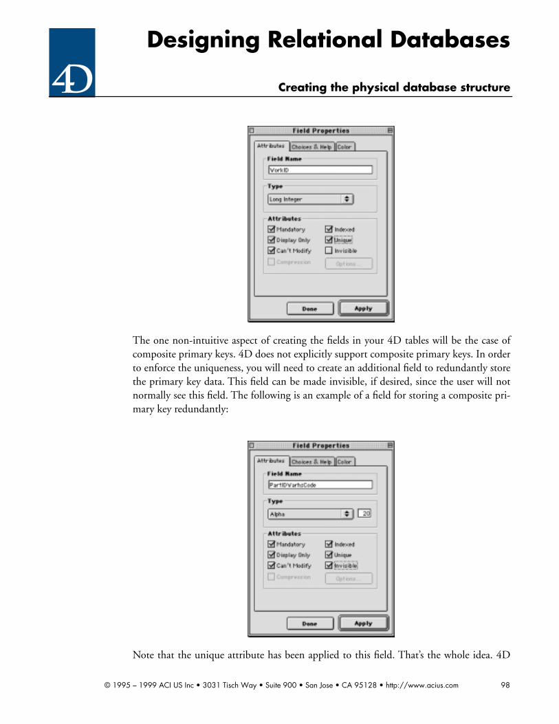
Designing Relational Databases
Creating the physical database structure
The one non-intuitive aspect of creating the fields in your 4D tables will be the case ofcomposite primary keys. 4D does not explicitly support composite primary keys. In orderto enforce the uniqueness, you will need to create an additional field to redundantly storethe primary key data. This field can be made invisible, if desired, since the user will notnormally see this field. The following is an example of a field for storing a composite pri-mary key redundantly:
Note that the unique attribute has been applied to this field. That’s the whole idea. 4D
© 1995 – 1999 ACI US Inc • 3031 Tisch Way • Suite 900 • San Jose • CA 95128 • http://www.acius.com 98

Designing Relational Databases
Creating the physical database structure
has to have a single field to evaluate the uniqueness of a value. The fields which are thecomponents of the primary key would have the attributes mandatory, can’t modify andindexed.
In this case, the value stored in the PartIDWarhsCode field would be something like“123-A” where “123” represents the string equivalent of the PartID and “A” representsthe Warehouse Code.
11.3.2 Entering non-key fields
Entering the other fields into the structure present no special problem. Simply followyour design and enter a matching field for each column, making appropriate adjustmentsfor field name length limitations. The following is the structure for the art museum data-base described earlier.
11.3.3 Establishing relations
4D contains a feature which allows for the automatic maintenance of relations betweentables. This feature requires that the relations be established in the structure editor. Doingthis is simple. Click on the foreign key field of the many table and drag to the primary keyof the one table. This operation opens the relation dialog, as follows:
© 1995 – 1999 ACI US Inc • 3031 Tisch Way • Suite 900 • San Jose • CA 95128 • http://www.acius.com 99

Designing Relational Databases
Creating the physical database structure
After the relation is established, 4D displays the following relation line:
© 1995 – 1999 ACI US Inc • 3031 Tisch Way • Suite 900 • San Jose • CA 95128 • http://www.acius.com 100

Designing Relational Databases
Creating the physical database structure
This indicates that the relation will be automatically maintained by 4D.
Exercises: Creating the physical database structure
Exercise 11.1
➔ Refer to Exercises 5.8 and 6.6. Create a physical database structure representing thisdatabase. Ignore issues of security.
Exercise 11.2
➔ Refer to Exercises 5.9 and 6.7. Create a physical database structure representing thisdatabase. Ignore issues of security.
Exercise 11.3
➔ Refer to Exercises 5.10 and 6.8. Create a physical database structure representing thisdatabase. Ignore issues of security.
Exercise 11.4
➔ Refer to Exercises 5.11 and 6.9. Create a physical database structure representing thisdatabase. Ignore issues of security.
© 1995 – 1999 ACI US Inc • 3031 Tisch Way • Suite 900 • San Jose • CA 95128 • http://www.acius.com 101

Designing Relational Databases
Final Exercise
12 Final Exercise
12.1 Moscow State
You have been hired to design the Moscow State Computer System for handling class reg-istration and related data.
Moscow State would like to track the following types of information:
• Student information for keeping track of where students are located, their majors andminors, grades, degree, class
• Class information in the form of descriptions, multiple offerings, instructors, pre-req-uisites, books needed, locations for class, equipment needed to teach the class, studentmaterials required
• Department information, department chairmen, faculty in department, and thedepartmental weekly meeting
• Faculty information for doing mailings, tracking their degrees, etc.
The following is an excerpt from their letter to us requesting your services.
• “Moscow Stare has approximately 50,000 students and offers about 2,000 courses in20 different departments, with 45 different degrees awarded. We are very concernedabout storage requirements because computer systems are still hard to come by here.We would like to eventually add our class history to the system consisting of datagoing back to the downfall of the czar. We have been promised by our government a 6user 4th Dimension Server and 7 computers to devote to this project. The server com-puter has a 2 G Hard Disk.
Data to be Stored
Students Classes Departments Faculty
Name Name Name Name
Address Credits Head Address
Phone Dates Faculty Department
Grades Times Meeting Date Degrees
Credits Department Meeting Time Office Location
Department Instructors Meeting Location Office Phone
Majors Books Classes Office Hrs.
Minors Location Home Phone
Degree` Prerequisites Classes
© 1995 – 1999 ACI US Inc • 3031 Tisch Way • Suite 900 • San Jose • CA 95128 • http://www.acius.com 102

Designing Relational Databases
Final Exercise
Class (Fr,So,Jr,Sr) Teaching Equipment Publications
Books Needed Student Materials
Materials Needed
Data to be Stored
Students Classes Departments Faculty
© 1995 – 1999 ACI US Inc • 3031 Tisch Way • Suite 900 • San Jose • CA 95128 • http://www.acius.com 103

Designing Relational Databases
Appendix A References
Reference 1
Code Complete, a Practical Handbook of Software Construction, by Steve McConnell(Microsoft Press, 1993)
This book is the most complete book on software construction which we have found. It isrequired reading by all programmers at Microsoft. It contains some useful tips on softwaredesign as well, oriented primarily towards helping the programmer know if the design hasbeen done properly.
Reference 2
Relational Database Design, a Practitioner’s Guide, by Charles J. Wertz (CRC Press 1993)
This book is a good intermediate textbook on relational database design using conven-tional structured analysis. It is fairly technical. This guide draws heavily from the materialin this book.
Reference 3
An Introduction to Database Systems, Volume I, by C.J. Date (Addison Wesley 1990)
This book is probably the most widely used college textbook on relational database the-ory. It is oriented primarily towards people who are design relational database manage-ment systems, not those who are designing relational databases. However, it does includea section on database design. It is written at a very high technical level. Definitely not forthe faint of heart.
Reference 4
An Introduction to Database Systems, Volume II, by C.J. Date (Addison Wesley 1983)
This book completes Date’s seminal work on relational database theory. Like Volume 1, itis at a very high level.
Reference 5
Rapid System Development Using Structured Analysis and Relational Technology, byChris Gane (Prentice Hall 1989)
Gane is the originator of the RAD (Rapid Application Development) approach to systemsdevelopment. This book contains his methodology, which borrows heavily from JAD(Joint Application Development). His book also contains a very good introductory leveltreatment of relational database design. If you are a student seeking a way to get familiarwith relational concepts quickly and easily, this is probably the best book for you. Thisguide also borrow heavily from the material in this book.
© 1995 – 1999 ACI US Inc • 3031 Tisch Way • Suite 900 • San Jose • CA 95128 • http://www.acius.com 104

Designing Relational Databases
Reference 6
The Relational Model for Database Management, Version 2, by E.F. Codd (Addison Wes-ley 1990)
Codd is the originator of the relational model of database management. In his work atIBM during the 1970’s Codd was responsible for designing the system which becameknown as DB2. His contribution to our industry is immense. Unfortunately, his book isalmost completely unreadable unless you have a Ph.D. is computer science. Unless youare very technical, stick with one of the other references shown above.
© 1995 – 1999 ACI US Inc • 3031 Tisch Way • Suite 900 • San Jose • CA 95128 • http://www.acius.com 105

Designing Relational Databases
Appendix B Solutions to exercises
Chapter 2 exercises
Exercise 2.1
The university’s collection of letters is not a database because it is not structured. In orderfor a collection of data to be a database it must be organized or structured in some way.
The university staff cannot find a letter for any particular student easily because the data isnot structured. To find any particular student’s letter would require reading all letters oneby one until the desired letter is found.
Similarly, the university staff could not sort the letters by state and city without examiningthe entirety of every letter.
The university’s collection of tear-off cards is a database because it is organized into logicalfields or columns.
The university staff can now more easily find a particular student’s card by simply scan-ning the cards and looking in the one blank for student name. (Having the cards in a 4Ddatabase would make this easier, of course.)
The university staff can also now more easily sort the cards, by simply ordering them bythe data in any given blank, or set of blanks.
Exercise 2.2
The data structure shown is not a table. It is three-dimensional. Tables are only two-dimensional
A search for all parts stored in warehouse B would require a sequential scan of everyrecord on disk (assuming of course that there is not some sort of an index structure tosupport this).
Sorting the parts by total quantity stored would require a lot of programming. Basicallyyou would have to go to every [Part] record one at a time and add up the total quantitystored. Then you would have to save that information into another structure, which couldthen be sorted.
Notice also the large amount of wasted space the data occupies on disk. This is technicallyknown as a sparse matrix.
These problems were typical in network and hierarchical databases which preceded therelational database model.
© 1995 – 1999 ACI US Inc • 3031 Tisch Way • Suite 900 • San Jose • CA 95128 • http://www.acius.com 106

Designing Relational Databases
Exercise 2.3
The primary key of the [Item] table is [Item]Item Number.
The primary key of the [Order] table is [Order]Order Number.
There is a candidate natural key in the [Item] which is [Item]Item Description. If this col-umn did not change (i.e. was permanent), it would work as a primary key.
Both of the primary keys of these tables are synthetic.
The tables are related on the [Item]Item Number column. The relation is 1:M. That is,there can be many orders for an item, but only one item for an order. The latter limitationis a defect which is corrected in the second version of the tables shown in the followingexercise.
The foreign key is [Order]Item Number.
Exercise 2.4
The primary key of the [Item] table is [Item]Item Number.
The primary key of the [Order] table is [Order]Order Number.
The primary key of the [Order Item] table is [Order Item]Order Number + [OrderItem]Item Number. This is a composite key.
There is a candidate natural key in the [Item] which is [Item]Item Description. If this col-umn did not change (i.e. was permanent), it would work as a primary key. Also, the pri-mary key of [Order Item] is a natural key.
There are now two 1:M relations which implement a single M:M relation.
The [Order Item] table is related to the [Order] table on the column Order Number. Thisrelation is 1:M with [Order] being the one table and [Order Item] being the many table.
The [Order Item] table is also related to the [Item] table on the column Item Number.This relation is 1:M with [Item] being the one table and [Order Item] being the manytable.
[Order Item] is therefore a linking table for a M:M relation between [Order] and [Item].
There are two foreign keys: [Order Item]Order Number and [Order Item]Item Number.
Exercise 2.5
There are two composite columns: [Person]Name and [Person]CSZ. These columns needto be broken up into atomic columns.
[Person]Name should be broken up into [Person]First Name and [Person]Last Name (andpossibly [Person]MI).
[Person]CSZ should be broken up into [Person]City, [Person]State and [Person]Zip
© 1995 – 1999 ACI US Inc • 3031 Tisch Way • Suite 900 • San Jose • CA 95128 • http://www.acius.com 107

Designing Relational Databases
Code.
You cannot look for persons with a specific last name, because you cannot identify thelocation of the last name in the [Person]Name column. There is no solution for this prob-lem (other than reorganizing the structure, of course). Trying to locate the last name inthe data by string parsing will be unreliable.
You cannot sort the data last name, because you cannot identify the location of the lastname in the [Person]Name column. There is no solution for this problem (other thanreorganizing the structure, of course). Trying to locate the last name in the data by stringparsing will be unreliable.
You cannot look for persons with who live in Texas, because you cannot identify the loca-tion of the state in the [Person]CSZ column. There is no feasible solution for this prob-lem (other than reorganizing the structure, of course). Trying to locate the state in thedata by string parsing will be unreliable.
You cannot sort by zip code, because you cannot identify the location of the zip code inthe [Person]CSZ column. There is no solution for this problem (other than reorganizingthe structure, of course). Trying to locate the zip code in the data by string parsing will beunreliable.
© 1995 – 1999 ACI US Inc • 3031 Tisch Way • Suite 900 • San Jose • CA 95128 • http://www.acius.com 108

Designing Relational Databases
Chapter 4 exercises
Exercise 4.1
You are more clearly able to see the relationships between the tables, as well as the rela-tionships between the columns and the primary keys in each table.
Once tables become fairly complex (say above ten columns) the sample data viewbecomes unmanageable, and you have to use an entity/attribute view to grasp the table asa whole.
Chapter 5 exercises
Exercise 5.1
Here are all of the functional dependencies:
[Inventory]Inventory Number –> [Inventory]Species
[Inventory]Inventory Number –> [Inventory]Breed
[Inventory]Inventory Number –> [Inventory]Acquired
[Inventory]Breed –> [Inventory]Species
Item
Column Names Data Types Keys
Item Number Longint PK
Item Description String (80)
Price Real
Order
Column Names Data Types Keys
Order Number Longint PK
Customer Number Longint
Order Date Date
Order Item
Column Names Data Types Keys
Order Number Longint PK1 FK1
Item Number Longint PK2 FK2
Quantity Real
© 1995 – 1999 ACI US Inc • 3031 Tisch Way • Suite 900 • San Jose • CA 95128 • http://www.acius.com 109

Designing Relational Databases
[Feeding Plan]Breed –> [Feeding Plan]Species
[Feeding Plan]Breed –> [Feeding Plan]Feed
[Feeding Plan]Breed –> [Feeding Plan]Quantity
The second question is a hint. These tables are not normalized. They violate 3NF. Youwill learn more about this later in the chapter.
Notice that you can determine the species from the breed in both tables. Thus:
[Inventory]Breed –> [Inventory]Species
and
[Feeding Plan]Breed –> [Feeding Plan]Species
That means that the tables violate 3NF. The [Inventory]Species and [Feeding Plan]Spe-cies columns are both dependent upon two columns.
Exercise 5.2
There are four repeating groups in this structure:
Appointments Date
Appointments Time
Symptoms
Diagnosis
The combination of multiple Boolean and text columns for things like Measles, Mumps,Chicken pox, EPT shot etc., constitutes another repeating group. (This one was subtle.)
There is more than one correct solution for this problem. The following describes a cor-rect solution.
The Appointments Date and Appointments Time group should be removed to anothertable called [Appointments] which stores data concerning the specific office visit. Bydoing so, the limitation on the number of appointments stored is removed.
Unless there is a need to search on specific symptom, the Symptom group can be replacedby a text column. Since the symptom is most likely related to a specific office visit the datacan be accommodated in this table. Otherwise, this group should be replaced with arelated table.
Unless there is a need to search on a specific diagnosis, the Diagnosis group can bereplaced by a text column. Since the diagnosis most likely related to a specific office visitthe data can be accommodated in this table. An individual diagnosis may not necessarilybe related to symptoms reported. Otherwise, this group should be replaced with a relatedtable.
The combination of multiple Boolean and date columns for things like Measles, Mumps.Chicken pox, DPT shot we will refer to as the Patient History group. This is the “big win”
© 1995 – 1999 ACI US Inc • 3031 Tisch Way • Suite 900 • San Jose • CA 95128 • http://www.acius.com 110

Designing Relational Databases
in correcting this structure. By moving this data into a related table, we make it possibleto reorganize and update the health history at any time. Storing information about a dis-ease, vaccination or other significant health history item is no needed. Plus in the event itbecomes important to store a new disease in the patient history such as Malaria it can beeasily added to the health history without redesigning the database. Also the absence ofthe data from the record indicates that the patient has never had this disease or vaccina-tion.
Here is the new structure:
A system such as that shown above is called data driven. This is one of the most powerfulaspects of relational database technology.
This exercise points out the dangers of automating a paper process. While your doctor is
Patient Record
Column Names Data Types Keys
Patient ID Longint PK
Patient Last Name String (45)
Patient First Name String (45)
Patient Birth Date Text
Allergies Text
Appointments
Column Names Data Types Keys
Patient ID Longint PK1 FK1
Appointment Date Date PK2
Appointment Time Time
Symptoms Text
Diagnosis Text
Health History
Column Names Data Types Keys
Patient ID Longint PK1 FK1
Item Name String (45) PK2
Item Date Date PK3
© 1995 – 1999 ACI US Inc • 3031 Tisch Way • Suite 900 • San Jose • CA 95128 • http://www.acius.com 111

Designing Relational Databases
very comfortable with the paper form process which is currently in place, she must under-stand (or be made to understand) that a paper system and a computerized system are twofundamentally different things. Simply automating a paper system can result in a disas-trous failure. (On the other hand, paper forms supply vital information on the nature ofthe data, as we will see when we get to data modeling.)
Exercise 5.3
There are two repeating groups in the proposed data structure.
• The first is the combination of Total Sales and Avg Sales on a monthly basis in the[Monthly Data] table.
• The second is the combination of Total Sales and Avg Sales on a monthly basis in the[Quarterly Data] table.
This type of error is extremely common among people who are familiar with spreadsheetsand who attempt to cross over into relational database design.
There is more than one correct solution to this problem. The following describes a correctsolution.
We combine all three tables into one table which performs the calculations on the basis ofa start date and an end date. Then, by simply entering the appropriate data, a financialanalyst can perform the calculations on any period he or she likes.
Here is the normalized structure:
One question you are probably asking is how we are going to do an annual rolling averagebased upon any given period. The answer is simple.
If the period is less than six months, we will divide the last year into any number of equalperiods ending with this one. (If this cannot be done evenly, we will generate an error andleave the [Periodic Data]Avg Sales column blank.)
We will then calculate [Periodic Data]Avg Sales based upon these periods.
If the period is more than six months, we will leave the [Periodic Data]Avg Sales columnblank.
Periodic Data
Column Names Data Types Keys
Start Date Date PK1
End Date Date PK2
Total Sales Real
Avg Sales Real
© 1995 – 1999 ACI US Inc • 3031 Tisch Way • Suite 900 • San Jose • CA 95128 • http://www.acius.com 112

Designing Relational Databases
This is another example of data driven programming.
Exercise 5.4
Whoever the insurance company’s developer was, he or she did not understand normal-ization.
Here are the functional dependencies:
Carrier ID –> Carrier Name
Carrier ID + Policy Number –> Customer ID
Carrier ID + Policy Number –> Customer Last Name
Carrier ID + Policy Number –> Customer First Name
Carrier ID + Policy Number –> Customer First Name
Customer ID –> Customer Last Name
Customer ID –> Customer First Name
Thus, we see that there is a violation of 2NF. Carrier Name is dependent on Carrier IDonly. This is not the entire primary key of [Policy]. Thus the table is not in 2NF.
By the way, there is also a violation of 3NF. If you caught that you are catching on. Cus-tomer Last Name and Customer First Name are dependent on the entire primary key of[Policy], but this is a transitive dependency. That is, this dependency is second-hand, byway of Customer ID. That means the table is not in 3NF either.
Here are the correctly normalized tables:
Policy
Column Names Data Types Keys
Carrier ID Longint PK1 FK1
Policy Number String (10) PK2
Customer ID Longint FK2
Carrier
Column Names Data Types Keys
Carrier ID Longint PK
Carrier Name String (45)
Customer
Column Names Data Types Keys
Customer ID Longint PK
© 1995 – 1999 ACI US Inc • 3031 Tisch Way • Suite 900 • San Jose • CA 95128 • http://www.acius.com 113
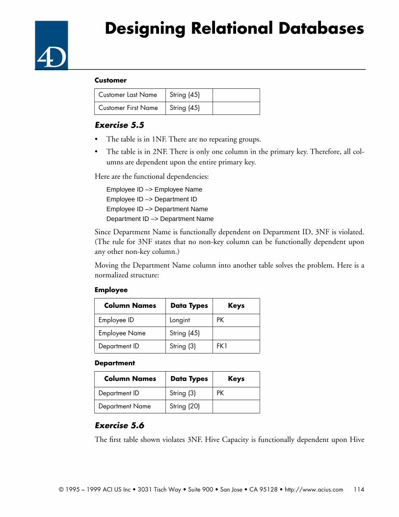
Designing Relational Databases
Exercise 5.5
• The table is in 1NF. There are no repeating groups.
• The table is in 2NF. There is only one column in the primary key. Therefore, all col-umns are dependent upon the entire primary key.
Here are the functional dependencies:
Employee ID –> Employee Name
Employee ID –> Department ID
Employee ID –> Department Name
Department ID –> Department Name
Since Department Name is functionally dependent on Department ID, 3NF is violated.(The rule for 3NF states that no non-key column can be functionally dependent uponany other non-key column.)
Moving the Department Name column into another table solves the problem. Here is anormalized structure:
Exercise 5.6
The first table shown violates 3NF. Hive Capacity is functionally dependent upon Hive
Customer Last Name String (45)
Customer First Name String (45)
Employee
Column Names Data Types Keys
Employee ID Longint PK
Employee Name String (45)
Department ID String (3) FK1
Department
Column Names Data Types Keys
Department ID String (3) PK
Department Name String (20)
Customer
© 1995 – 1999 ACI US Inc • 3031 Tisch Way • Suite 900 • San Jose • CA 95128 • http://www.acius.com 114

Designing Relational Databases
ID and therefore does not belong in the table. The correct structure is:
The second table shown violates 2NF. Person Name is functionally dependent upon Per-son ID only and therefore does not belong in the table. The correct structure is:
Here are the only additional tables necessary for completely normalized structure:
Bee
Column Names Data Types Keys
Bee ID Longint PK
Name String (20)
Hive ID Longint FK1
Sting
Column Names Data Types Keys
Bee ID Longint PK1
Person ID Longint PK2
Number of Stings Integer
Hive
Column Names Data Types Keys
Hive ID Longint PK
Hive Capacity Longint
Hive Phone Number String (10)
Flower
Column Names Data Types Keys
Flower ID Longint PK
Flower Type String (45)
Color String (10)
Pollination
Column Names Data Types Keys
Bee ID Longint PK1 FK1
© 1995 – 1999 ACI US Inc • 3031 Tisch Way • Suite 900 • San Jose • CA 95128 • http://www.acius.com 115

Designing Relational Databases
These tables, along with the ones shown above, constitute a completely normalized struc-ture because all functional dependencies are implemented and none of the rules of nor-malization are violated.
Exercise 5.7
Here are the functional dependencies:
Shepherd ID –> Shepherd Name
Shepherd ID –> Shepherd Size
Pen ID –> Pen Value
Pen ID –> Pen Capacity
Pen ID –> Shepherd ID
Sheep ID –> Pen ID
Sheep ID –> Sheep Weight
Sheep ID –> Sheep Value
Here is the normalized data structure:
Pollination Date Date PK2
Pollination Time Time PK3
Flower ID Longint FK2
Person
Column Names Data Types Keys
Person ID Longint PK
Person Name String (80)
Shepherd
Column Names Data Types Keys
Shepherd ID Longint PK
Shepherd Name String (80)
Shepherd Size Integer
Pen
Column Names Data Types Keys
Pen ID Longint PK
Pen Value Real
Pollination
© 1995 – 1999 ACI US Inc • 3031 Tisch Way • Suite 900 • San Jose • CA 95128 • http://www.acius.com 116

Designing Relational Databases
These tables constitute a completely normalized structure because all functional depen-dencies are implemented and none of the rules of normalization are violated.
Exercise 5.8
Here are the functional dependencies:
Magician ID –> Magician Name
Magician ID –> Magician Rate
Club Name –> Club Address
Club Name –> Club Phone
Trick ID –> Trick Name
Trick ID –> Trick Amazing
Trick ID + Magician ID –> Trick Competency
There are some other issues in this problem. Due to the fact that Club Name can change,it doesn’t work as a primary key. We also need to implement a M:M relationship between[Magician] and [Club].
Here is the normalized data structure:
Pen Capacity Real
Shepherd ID Longint FK1
Sheep
Column Names Data Types Keys
Sheep ID Longint PK
Sheep Value Real
Sheep Weight Real
Pen ID Longint FK1
Wizard
Column Names Data Types Keys
Magician ID Longint PK
Magician Name String (80)
Magician Rate Real
Club
Column Names Data Types Keys
Pen
© 1995 – 1999 ACI US Inc • 3031 Tisch Way • Suite 900 • San Jose • CA 95128 • http://www.acius.com 117

Designing Relational Databases
These tables constitute a completely normalized structure because all functional depen-dencies are implemented and none of the rules of normalization are violated.
Exercise 5.9
Here are the functional dependencies:
Trainer ID –> Trainer Name
Trainer ID –> Trainer Size
Horse Barn ID –> Horse Barn Value
Horse Barn ID –> Horse Barn Capacity
Horse Barn ID –> Trainer ID
Horse ID –> Horse Barn ID
Horse ID –> Horse Weight
Club ID Longint PK
Club Name String (80)
Club Address String (80)
Club Phone String (10)
Spell
Column Names Data Types Keys
Trick ID Longint PK
Trick Name String (80)
Trick Amazing Integer
Magician Club
Column Names Data Types Keys
Magician ID Longint PK1 FK1
Club ID Longint PK2 FK2
Magician Spell
Column Names Data Types Keys
Magician ID Longint PK1 FK1
Trick ID Longint PK2 FK2
Trick Competency Integer
Club
© 1995 – 1999 ACI US Inc • 3031 Tisch Way • Suite 900 • San Jose • CA 95128 • http://www.acius.com 118

Designing Relational Databases
Horse ID –> Horse Value
Here is the normalized data structure:
These tables constitute a completely normalized structure because all functional depen-dencies are implemented and none of the rules of normalization are violated.
Exercise 5.10
Here are the functional dependencies:
Painter ID –> Painter Name
Painter ID –> Painter Rate
Club Name –> Club Address
Club Name –> Club Phone
Painter ID –> Medium Name
Medium ID –> Medium Skill
Medium ID + Painter ID –> Medium Competency
Trainer
Column Names Data Types Keys
Trainer ID Longint PK
Trainer Name String (80)
Trainer Size Integer
Horse Barn
Column Names Data Types Keys
Horse Barn ID Longint PK
Horse Barn Value Real
Horse Barn Capacity Real
Trainer ID Longint FK1
Horse
Column Names Data Types Keys
Horse ID Longint PK
Horse Value Real
Horse Weight Real
Horse Barn ID Longint FK1
© 1995 – 1999 ACI US Inc • 3031 Tisch Way • Suite 900 • San Jose • CA 95128 • http://www.acius.com 119

Designing Relational Databases
There are some other issues in this problem. Due to the fact that Club Name can change,it doesn’t work as a primary key. We also need to implement a M:M relationship between[Painter] and [Club]. Here is the normalized data structure:
Painter
Column Names Data Types Keys
Painter ID Longint PK
Painter Name String (80)
Painter Rate Real
Club
Column Names Data Types Keys
Club ID Longint PK
Club Name String (80)
Club Address String (80)
Club Phone String (10)
Medium
Column Names Data Types Keys
Medium ID Longint PK
Medium Name String (80)
Medium Skill Integer
Painter Club
Column Names Data Types Keys
Painter ID Longint PK1 FK1
Club ID Longint PK2 FK2
Painter Medium
Column Names Data Types Keys
Painter ID Longint PK1 FK1
Medium ID Longint PK2 FK2
Medium Competency Integer
© 1995 – 1999 ACI US Inc • 3031 Tisch Way • Suite 900 • San Jose • CA 95128 • http://www.acius.com 120

Designing Relational Databases
These tables constitute a completely normalized structure because all functional depen-dencies are implemented and none of the rules of normalization are violated.
Chapter 6 exercises
Exercise 6.1
Here is the ERD:
Remember that this data structure is not correctly normalized. See the solution to Exer-cise 5.1 for details.
Exercise 6.2
Here is the ERD:
Exercise 6.3
Here is the ERD:
Inventory Feeding PlanM 1
Controlled By
Appointments
Health History
Patient
M
M
1
1
Has
Has had
Policy
CustomerCarrier 1 1
M MIssues Is Issued To
© 1995 – 1999 ACI US Inc • 3031 Tisch Way • Suite 900 • San Jose • CA 95128 • http://www.acius.com 121

Designing Relational Databases
Exercise 6.5
Here is the ERD:
Exercise 6.6
Here is the ERD:
Bee
StingHive 1 M
M 1Contains Commits
Person
M
1
Affects
Pollination
M
1
Is Performed by
Flower
1
M
Is Fertilized by
© 1995 – 1999 ACI US Inc • 3031 Tisch Way • Suite 900 • San Jose • CA 95128 • http://www.acius.com 122

Designing Relational Databases
Exercise 6.7
Here is the ERD:
Exercise 6.8
Here is the ERD:
Pig
Pigpen
1
M
Contains
Swineherd
1
M
Cares for
Wizard
Wizard SpellWizard Lodge M M
1 1Belongs to Conjures
Spell
M
1
References
Lodge
M
1
References
© 1995 – 1999 ACI US Inc • 3031 Tisch Way • Suite 900 • San Jose • CA 95128 • http://www.acius.com 123

Designing Relational Databases
Exercise 6.9
Here is the ERD:
Exercise 6.10
Here are the functional dependencies:
Pirate Nickname –> Pirate Christian Name
Pirate Nickname –> Pirate Ferocity Rating
Pirate Nickname –> Pirate Date of First Piracy
Pirate Nickname –> Pirate Ship Name
Pirate Ship Name –> Pirate Ship Number of Masts
Pirate Ship Name –> Pirate Ship Number of Cannon
Horse
Horse Barn
1
M
Contains
Trainer
1
M
Cares for
CraftsPerson
Crafts PersonCraft
Crafts PersonGuild M M
1 1Belongs to Crafts
Craft
M
1
References
Guild
M
1
References
© 1995 – 1999 ACI US Inc • 3031 Tisch Way • Suite 900 • San Jose • CA 95128 • http://www.acius.com 124
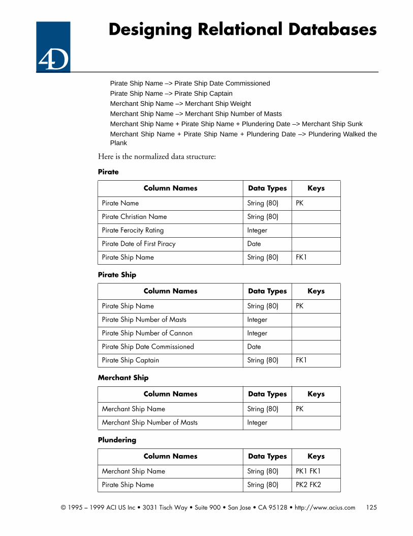
Designing Relational Databases
Pirate Ship Name –> Pirate Ship Date Commissioned
Pirate Ship Name –> Pirate Ship Captain
Merchant Ship Name –> Merchant Ship Weight
Merchant Ship Name –> Merchant Ship Number of Masts
Merchant Ship Name + Pirate Ship Name + Plundering Date –> Merchant Ship Sunk
Merchant Ship Name + Pirate Ship Name + Plundering Date –> Plundering Walked thePlank
Here is the normalized data structure:
Pirate
Column Names Data Types Keys
Pirate Name String (80) PK
Pirate Christian Name String (80)
Pirate Ferocity Rating Integer
Pirate Date of First Piracy Date
Pirate Ship Name String (80) FK1
Pirate Ship
Column Names Data Types Keys
Pirate Ship Name String (80) PK
Pirate Ship Number of Masts Integer
Pirate Ship Number of Cannon Integer
Pirate Ship Date Commissioned Date
Pirate Ship Captain String (80) FK1
Merchant Ship
Column Names Data Types Keys
Merchant Ship Name String (80) PK
Merchant Ship Number of Masts Integer
Plundering
Column Names Data Types Keys
Merchant Ship Name String (80) PK1 FK1
Pirate Ship Name String (80) PK2 FK2
© 1995 – 1999 ACI US Inc • 3031 Tisch Way • Suite 900 • San Jose • CA 95128 • http://www.acius.com 125

Designing Relational Databases
And here is the ERD:
Chapter 7 exercises
Exercise 7.1
There is more than one solution to this problem. The following describes a correct solu-tion.
Huey may be a smart lawyer, but he’s a wash-up as a relational database designer. (Ofcourse, you can’t tell him that.)
Here are the composite columns (this one was pretty easy):
Client CSZ
Defendant Name
Defendant CSZ
Opposing Atty Name
Plundering Date Date PK3
Plundering Merchant Ship Sunk Boolean
Plundering Walked the Plank Integer
Plundering
Pirate
Pirate Ship1
M
Is Part of Crew
Plundering
1
M
Participates in
1
1
Is Captain
MerchantShip
M
1
Is a Victim in
© 1995 – 1999 ACI US Inc • 3031 Tisch Way • Suite 900 • San Jose • CA 95128 • http://www.acius.com 126

Designing Relational Databases
Physician Name
Obviously, these composite columns need to be replaced with atomic columns containingthe same data. Here are the new columns:
Client City
Client State
Client Zip Code
Defendant Last Name
Defendant First Name
Defendant MI
Defendant City
Defendant State
Defendant Zip Code
Opposing Atty Last Name
Opposing Atty First Name
Opposing Atty MI
Physician Last Name
Physician First Name
Physician MI
Remember the rules for choosing a primary key:
• The primary key must uniquely identify every row in the table
• The primary key must be permanent (i.e. unchanging) over the life of the row
• The primary key must be mandatory (i.e. defined in every row).
Huey has some problems with the second and third rules.
Take [Client] for example. The choice of a primary key consisting of the combination ofClient Last Name, Client First Name and Client MI is poor. Many people do not use amiddle initial. (Indeed, some people don’t even use a last name, e.g. Prince, Sting andMadonna.) Thus, all of these columns cannot be made mandatory.
Also, we have seen that people tend to change their names. Thus, Huey’s choice of pri-mary key for this table is not permanent. We need to create a synthetic key for the [Cli-ent] table. We will call this key Client ID.
The same problem exists with the primary key for the [Ad] table. How many times donewspapers change their names? The Chicago Tribune used to be the Chicago Star, theDallas Times Herald was bought out by the Dallas Morning News, and so on.
The problem here is that we do not have a table to store [Advertiser] and we need one. Inorder to create a primary key which works for the [Ad] table, we need a synthetic key for
© 1995 – 1999 ACI US Inc • 3031 Tisch Way • Suite 900 • San Jose • CA 95128 • http://www.acius.com 127
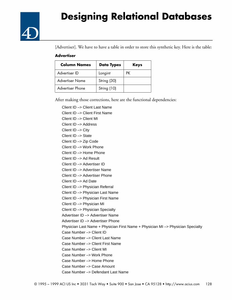
Designing Relational Databases
[Advertiser]. We have to have a table in order to store this synthetic key. Here is the table:
After making those corrections, here are the functional dependencies:
Client ID –> Client Last Name
Client ID –> Client First Name
Client ID –> Client MI
Client ID –> Address
Client ID –> City
Client ID –> State
Client ID –> Zip Code
Client ID –> Work Phone
Client ID –> Home Phone
Client ID –> Ad Result
Client ID –> Advertiser ID
Client ID –> Advertiser Name
Client ID –> Advertiser Phone
Client ID –> Ad Date
Client ID –> Physician Referral
Client ID –> Physician Last Name
Client ID –> Physician First Name
Client ID –> Physician MI
Client ID –> Physician Specialty
Advertiser ID –> Advertiser Name
Advertiser ID –> Advertiser Phone
Physician Last Name + Physician First Name + Physician MI –> Physician Specialty
Case Number –> Client ID
Case Number –> Client Last Name
Case Number –> Client First Name
Case Number –> Client MI
Case Number –> Work Phone
Case Number –> Home Phone
Case Number –> Case Amount
Case Number –> Defendant Last Name
Advertiser
Column Names Data Types Keys
Advertiser ID Longint PK
Advertiser Name String (30)
Advertiser Phone String (10)
© 1995 – 1999 ACI US Inc • 3031 Tisch Way • Suite 900 • San Jose • CA 95128 • http://www.acius.com 128
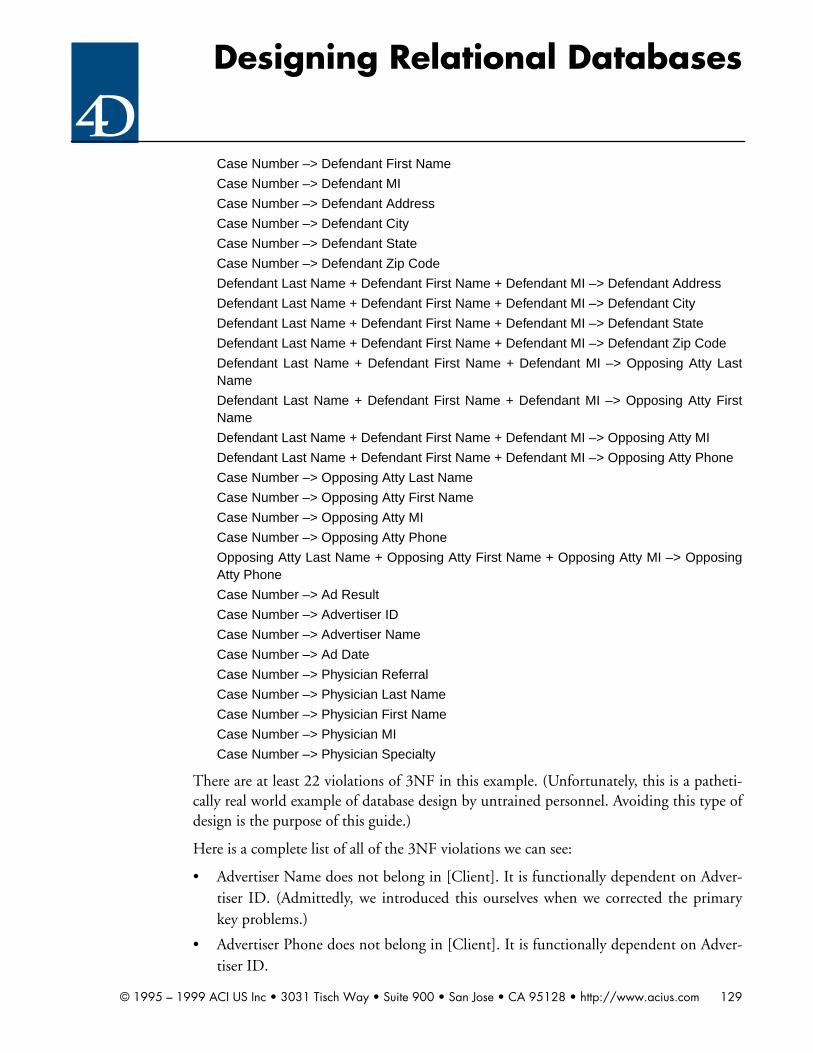
Designing Relational Databases
Case Number –> Defendant First Name
Case Number –> Defendant MI
Case Number –> Defendant Address
Case Number –> Defendant City
Case Number –> Defendant State
Case Number –> Defendant Zip Code
Defendant Last Name + Defendant First Name + Defendant MI –> Defendant Address
Defendant Last Name + Defendant First Name + Defendant MI –> Defendant City
Defendant Last Name + Defendant First Name + Defendant MI –> Defendant State
Defendant Last Name + Defendant First Name + Defendant MI –> Defendant Zip Code
Defendant Last Name + Defendant First Name + Defendant MI –> Opposing Atty LastName
Defendant Last Name + Defendant First Name + Defendant MI –> Opposing Atty FirstName
Defendant Last Name + Defendant First Name + Defendant MI –> Opposing Atty MI
Defendant Last Name + Defendant First Name + Defendant MI –> Opposing Atty Phone
Case Number –> Opposing Atty Last Name
Case Number –> Opposing Atty First Name
Case Number –> Opposing Atty MI
Case Number –> Opposing Atty Phone
Opposing Atty Last Name + Opposing Atty First Name + Opposing Atty MI –> OpposingAtty Phone
Case Number –> Ad Result
Case Number –> Advertiser ID
Case Number –> Advertiser Name
Case Number –> Ad Date
Case Number –> Physician Referral
Case Number –> Physician Last Name
Case Number –> Physician First Name
Case Number –> Physician MI
Case Number –> Physician Specialty
There are at least 22 violations of 3NF in this example. (Unfortunately, this is a patheti-cally real world example of database design by untrained personnel. Avoiding this type ofdesign is the purpose of this guide.)
Here is a complete list of all of the 3NF violations we can see:
• Advertiser Name does not belong in [Client]. It is functionally dependent on Adver-tiser ID. (Admittedly, we introduced this ourselves when we corrected the primarykey problems.)
• Advertiser Phone does not belong in [Client]. It is functionally dependent on Adver-tiser ID.
© 1995 – 1999 ACI US Inc • 3031 Tisch Way • Suite 900 • San Jose • CA 95128 • http://www.acius.com 129

Designing Relational Databases
• Physician Specialty is functionally dependent upon the combination of Physician LastName, Physician First Name and Physician MI. Therefore it does not belong in [Cli-ent].
• Client Last Name is functionally dependent upon Client ID. Therefore it does notbelong in [Case]. Ditto for Client First Name, Client MI, Work Phone and HomePhone.
• Defendant Address is functionally dependent upon the combination of DefendantLast Name, Defendant First Name and Defendant MI. Therefore it does not belongin [Case]. Ditto for Defendant City, Defendant State and Defendant Zip Code.
• Opposing Atty Last Name is functionally dependent upon the combination of Defen-dant Last Name, Defendant First Name and Defendant MI. Therefore it does notbelong in [Case]. Ditto for Opposing Atty First Name, Opposing Atty MI andOpposing Atty Phone.
• Opposing Atty Phone is functionally dependent upon the combination of OpposingAtty Last Name, Opposing Atty First Name and Opposing Atty MI. Therefore it doesnot belong in [Case].
• Ad Result is functionally dependent upon Client ID. Therefore it does not belong in[Case]. Ditto for Advertiser ID and Ad Date.
• Advertiser Name is functionally dependent upon Advertiser ID. Therefore it does notbelong in [Case].
After removing all of the 3NF violations by creating new tables and moving the offendingcolumns into them, and then adding the appropriate synthetic keys to the new tables, thefollowing is a correctly normalized database structure:
Client
Column Names Data Types Keys
Client ID Longint PK
Client Last Name String (45)
Client First Name String (45)
Client MI String (45)
Client Address Text
Client City String (45)
Client State String (2)
Client Zip Code String (9)
© 1995 – 1999 ACI US Inc • 3031 Tisch Way • Suite 900 • San Jose • CA 95128 • http://www.acius.com 130
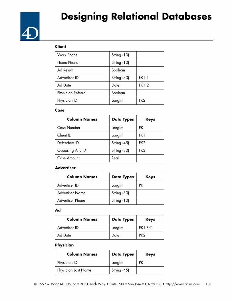
Designing Relational Databases
Work Phone String (10)
Home Phone String (10)
Ad Result Boolean
Advertiser ID String (30) FK1.1
Ad Date Date FK1.2
Physician Referral Boolean
Physician ID Longint FK2
Case
Column Names Data Types Keys
Case Number Longint PK
Client ID Longint FK1
Defendant ID String (45) FK2
Opposing Atty ID String (80) FK3
Case Amount Real
Advertiser
Column Names Data Types Keys
Advertiser ID Longint PK
Advertiser Name String (30)
Advertiser Phone String (10)
Ad
Column Names Data Types Keys
Advertiser ID Longint PK1 FK1
Ad Date Date PK2
Physician
Column Names Data Types Keys
Physician ID Longint PK
Physician Last Name String (45)
Client
© 1995 – 1999 ACI US Inc • 3031 Tisch Way • Suite 900 • San Jose • CA 95128 • http://www.acius.com 131

Designing Relational Databases
Here is the ERD:
Physician First Name String (45)
Physician MI String (2)
Physician Specialty String (45)
Defendant
Column Names Data Types Keys
Defendant ID Longint PK
Defendant Last Name String (45)
Defendant First Name String (45)
Defendant MI String (45)
Opposing Atty ID Longint FK1
Opposing Atty
Column Names Data Types Keys
Opposing Atty ID Longint PK
Opposing Atty Last Name String (45)
Opposing Atty First Name String (45)
Opposing Atty MI String (45)
Opposing Atty Phone String (10)
Physician
© 1995 – 1999 ACI US Inc • 3031 Tisch Way • Suite 900 • San Jose • CA 95128 • http://www.acius.com 132

Designing Relational Databases
This structure does not take into account the fact that there might be multiple defendantsin a case, or that a defendant might have multiple attorneys, both of which were ignoredby Huey. If either of both of these are the case, then further normalization is needed.
Given your client’s personality problems, convincing him that he’s wrong and you’re rightis going to be a little tough. A better approach might be to talk to him about how hemight improve “his” design. Then point out each defect one by one. Emphasize the factthat performance will be better and storage space less on each item. That will appeal to hissense of cheapness. Hopefully, each change will eventually become his idea. After aboutten defects, he may get the idea and voluntarily “deep six” his design in favor of one youcome up with. Otherwise, you will have to go through each of the defects one-by-one inthis manner.
If this is too much trouble, you’re not hungry enough. Better get yourself another client.
Exercise 7.2
There is more than one correct solution to this problem. The following describes a correctsolution.
Client
CaseAd 1 M
M 1Induced by Is A Party To
Advertiser
M
1
Published by
Defendant
M
1
Includes
Opposing Atty
M
1
Represents
Physician
M
1Referred by
© 1995 – 1999 ACI US Inc • 3031 Tisch Way • Suite 900 • San Jose • CA 95128 • http://www.acius.com 133

Designing Relational Databases
Here are the candidate entities:
[Publisher]
[Story]
[Reporter]
[Job]
[Subject]
Here are the attributes:
Publisher ID
Publisher Name
Story ID
Story Name
Reporter ID
Reporter Last Name
Reporter First Name
Job Start Date
Job End Date
Subject Key Word
Here are the functional dependencies:
Publisher ID –> Publisher Name
Story ID –> Story Name
Story ID –> Publisher ID
Story ID –> Reporter ID
Reporter ID –> Reporter Last Name
Reporter ID –> Reporter First Name
Reporter ID + Publisher ID + Job Start Date –> Job End Date
In addition, we can see that there is a M:M relationship between [Story] and [Subject]which we have implemented through another entity, [Subject Reference].
Here are the entity/attribute listings:
Publisher
Column Names Data Types Keys
Publisher ID Longint PK
Publisher Name String (30)
Reporter
Column Names Data Types Keys
© 1995 – 1999 ACI US Inc • 3031 Tisch Way • Suite 900 • San Jose • CA 95128 • http://www.acius.com 134

Designing Relational Databases
Here is the ERD:
Reporter ID Longint PK
Reporter Last Name String (80)
Reporter First Name
Story
Column Names Data Types Keys
Story ID Longint PK
Publisher ID Longint FK1
Reporter ID Longint FK2
Story Name String (80)
Subject
Column Names Data Types Keys
Subject Key Word String (80) PK
Subject Reference
Column Names Data Types Keys
Subject Key Word String (80) PK1 FK1
Story ID Longint PK2 FK2
Job
Column Names Data Types Keys
Publisher ID Longint PK1 FK1
Reporter ID Longint PK2 FK2
Job Start Date Date PK3
Job End Date
Reporter
© 1995 – 1999 ACI US Inc • 3031 Tisch Way • Suite 900 • San Jose • CA 95128 • http://www.acius.com 135

Designing Relational Databases
Chapter 8 exercises
Exercise 8.1
There is more than one correct solution to this problem. The following describes a correctsolution.
Solving this problem requires adding a new entity which we call [Job].
Here are the new functional dependencies:
Pirate Nickname + Pirate Ship Name + Job Start Date –> Job End Date
Pirate Nickname + Pirate Ship Name + Job Start Date –> Pirate Ship Captain
The latter functional dependency replaces the following one shown in the prior solution:
Pirate Nickname –> Pirate Ship Captain
Since we are now tracking a pirate’s career, and since a pirate can be captain multipletimes, we now have a 1:M relationship between a pirate ship and its captain.
Publisher
StoryM
1
Publishes
SubjectReference
1
M
References
Subject
M
1
References
Reporter
WritesM
1
Job
EmploysWorks at
MM
11
© 1995 – 1999 ACI US Inc • 3031 Tisch Way • Suite 900 • San Jose • CA 95128 • http://www.acius.com 136

Designing Relational Databases
Here is the new entity:
Here is the changed [Pirate Ship] entity:
Notice that Pirate Ship Captain has been converted from a string to a Boolean.
Here is the new ERD:
Job
Column Names Data Types Keys
Pirate Name String (80) PK1 FK1
Pirate Ship Name String (80) PK2 FK2
Job Start Date Date PK3
Job End Date Date
Pirate Ship Captain Boolean
Pirate Ship
Column Names Data Types Keys
Pirate Ship Name String (80) PK
Pirate Ship Number of Masts Integer
Pirate Ship Number of Cannon Integer
Pirate Ship Date Commissioned Date
© 1995 – 1999 ACI US Inc • 3031 Tisch Way • Suite 900 • San Jose • CA 95128 • http://www.acius.com 137

Designing Relational Databases
This is an extremely common modification to a database. Clients frequently discover thatthey need to store historical data rather than just current data. You must design your data-base with this in mind. If your database follows the rules of normalization, this type ofchange will be simple and easy. Otherwise, it may be difficult.
Exercise 8.2
This database requires a recursive approach. This is because individuals create offspringwho are in turn individuals. There are several correct solutions to this problem. The fol-lowing describes a correct solution.
Here are the entity/attribute listings:
Person
Column Names Data Types Keys
Person ID Longint PK
Pirate
Pirate Ship
Plundering
1
M
Participates in
MerchantShip
M
1
Is a Victim in
Job
M
1
Is Part of the Crew
1
M
Employs
© 1995 – 1999 ACI US Inc • 3031 Tisch Way • Suite 900 • San Jose • CA 95128 • http://www.acius.com 138

Designing Relational Databases
And here is the ERD:
Notice some subtle things about this design. First, it recognizes the practical fact that notall births occur within marriage. Thus, an offspring is related to its father and mother, notto a marriage.
Person Last Name String (80)
Person First Name String (80)
Date of Birth Date
Date of Death
Marriage
Column Names Data Types Keys
Man ID Longint PK1
Woman ID Longint PK2
Marriage Date Date PK3
Divorce Date Date
Offspring
Column Names Data Types Keys
Offspring ID Longint PK
Father ID Longint FK1
Woman ID Longint FK2
Person
Marriage
Person
Is WifeIs Husband11
MM
Offspring
MothersFathers
11
MM
Is A1
1
© 1995 – 1999 ACI US Inc • 3031 Tisch Way • Suite 900 • San Jose • CA 95128 • http://www.acius.com 139

Designing Relational Databases
Also, there is a three-way relationship between [Person], and [Offspring]. We considerDate of Birth to be an attribute of the [Person], not the [Offspring], but since this is a 1:1relationship, that is a matter of taste.
Exercise 8.3
There is more than one correct solution to this problem. The following describes a correctsolution. Here is the ERD:
Here are the entity/attribute listings:
Player
Column Names Data Types Keys
Player ID Longint PK
Player Last Name String (80)
Player First Name String (80)
Player Total Hits Integer
Player Total Times at Bat Integer
Player Total Attendance Integer
Team
PlayerSeason
M
1Plays During
Player
1
MPlays For
PlayerGame
Game
TeamGame
1 M
Plays In
1
MPlays In
1
MCompetes In
1
MCompetes In
Season
1
MIs Played In
TeamSeason
1
MParticipates In
M
1
ParticipatesIn
© 1995 – 1999 ACI US Inc • 3031 Tisch Way • Suite 900 • San Jose • CA 95128 • http://www.acius.com 140
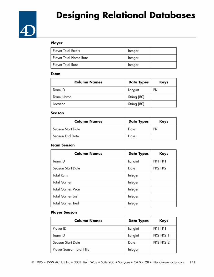
Designing Relational Databases
Player Total Errors Integer
Player Total Home Runs Integer
Player Total Runs Integer
Team
Column Names Data Types Keys
Team ID Longint PK
Team Name String (80)
Location String (80)
Season
Column Names Data Types Keys
Season Start Date Date PK
Season End Date Date
Team Season
Column Names Data Types Keys
Team ID Longint PK1 FK1
Season Start Date Date PK2 FK2
Total Runs Integer
Total Games Integer
Total Games Won Integer
Total Games Lost Integer
Total Games Tied Integer
Player Season
Column Names Data Types Keys
Player ID Longint PK1 FK1
Team ID Longint PK2 FK2.1
Season Start Date Date PK3 FK2.2
Player Season Total Hits Integer
Player
© 1995 – 1999 ACI US Inc • 3031 Tisch Way • Suite 900 • San Jose • CA 95128 • http://www.acius.com 141

Designing Relational Databases
Let’s take a look at how we satisfy each of the requirements of the exercise:
Player Season Total Times at Bat Integer
Player Season Total Attendance Integer
Player Season Total Errors Integer
Player Season Total Runs Integer
Player Season Total Home Runs Integer
Game
Column Names Data Types Keys
Game ID Longint PK
Game Date Date
Game Time Time
Location String (80)
Team Game
Column Names Data Types Keys
Team ID Longint PK1 FK1
Game ID Longint PK2 FK2
Start Boolean
Runs Integer
Player Game
Column Names Data Types Keys
Player ID Longint PK1 FK1
Ball Club ID Longint PK2 FK2.1
Game ID Longint PK3 FK2.2
Times at Bat Integer
Hits Integer
Errors Integer
Runs Integer
Home Runs Integer
Player Season
© 1995 – 1999 ACI US Inc • 3031 Tisch Way • Suite 900 • San Jose • CA 95128 • http://www.acius.com 142

Designing Relational Databases
Player statistics
• Batting average (by season)
• Player Season Total Hits divided by Player Season Total Times at Bat.
• Player Season Total Hits is posted from [Player Game]Hits.
• Player Season Total Times at Bat is posted from [Player Game]Times at Bat.
• Batting average (lifetime)
• Player Total Hits divided by Player Total Times at Bat.
• Player Total Hits is posted from [Player Game]Hits.
• Player Total Times at Bat is posted from [Player Game]Times at Bat.
• Attendance (by season)
• Player Season Total Attendance is posted from [Player Game] (simply the numberof rows in [Player Game] for a given season).
• Attendance (lifetime)
• Player Total Attendance is posted from [Player Game] (simply the number of rowsin [Player Game]).
• Average errors per game (by season)
• Player Season Total Errors divided by Player Season Total Attendance.
• Player Season Total Errors is posted from [Player Game]Errors.
• Average errors per game (lifetime)
• Player Total Errors divided by Player Total Attendance.
• Player Total Errors is posted from [Player Game]Errors.
• Runs (by season)
• Player Season Total Runs is posted from [Player Game]Runs.
• Runs (lifetime)
• Player Total Runs is posted from [Player Game]Runs.
• Home runs (by season)
• Player Season Total Home Runs is posted from [Player Game]Home Runs.
• Home runs (lifetime)
• Player Total Home Runs is posted from [Player Game]Home Runs.
Team statistics
• Total runs (by season)
• [Team Game]Runs is posted from [Player Game]Runs.
© 1995 – 1999 ACI US Inc • 3031 Tisch Way • Suite 900 • San Jose • CA 95128 • http://www.acius.com 143

Designing Relational Databases
• [Team Season]Total Runs is posted from [Team Game]Runs.
• Average runs per game (by season)
• [Team Season]Total Runs divided by [Team Season]Total Games.
• [Team Season]Total Games is posted from [Team Game] (simply the number of rowsin [Team Game] for a given season).
• Games won (by season)
• Of the two rows in [Team Game] related to any given [Game], the one with the mostruns (the highest value in [Team Game]Runs) is the winner. For that row, incrementthe Total Games Won column by one.
• Games lost (by season)
• Of the two rows in [Team Game] related to any given [Game], the one with the leastruns (the lowest value in [Team Game]Runs) is the loser. For that row, increment theTotal Games Lost column by one.
• Games tied (by season)
If the two rows in [Team Game] related to any given [Game] have the same number ofruns (identical values in [Team Game]Runs) there is a tie. Increment the Total GamesTied column by one for both teams.
Chapter 9 exercises
Exercise 9.1
There is more than one correct solution to this problem. The following describes a correctsolution.
Entity/relationship diagram:
© 1995 – 1999 ACI US Inc • 3031 Tisch Way • Suite 900 • San Jose • CA 95128 • http://www.acius.com 144

Designing Relational Databases
Data dictionary:
Entities:
[Client]
An individual who is either now or was at one time represented by the firm in a case.
[Case]
A single matter which has either been or is intended to be filed as a lawsuit in court. Thefirm represents the plaintiff in the case, and the opposing party is the defendant.
[Client]
An individual who is either now or was at one time represented by the firm in a case.
[Client Case]
The participation of a client in a case. This is the linking table for supporting the M:Mrelationship between [Client] and [Case].
[Ad]
A single unit of advertising run on a single day. An ad may be run more than once on thatday (as in radio or television ads). However, as a simplifying assumption, the firm onlytracks ads on a per-day basis.
[Physician]
A medical, osteopathic or chiropractic practitioner who is referring, or at one time
Client
Case
Ad1
MM 1
Induced by
Is A Party To
Advertiser
M
1
Published by
Party CaseAttorney
1
M
Is A Party To
Attorney
ClientCase
Referencedby
M
1
Physician
M
1
Referred by
Party
1
M
Represents
1 M
Referencedby
© 1995 – 1999 ACI US Inc • 3031 Tisch Way • Suite 900 • San Jose • CA 95128 • http://www.acius.com 145
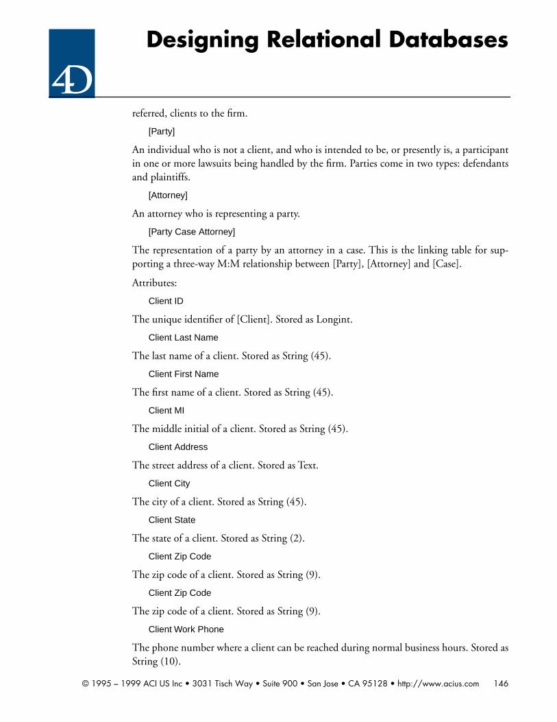
Designing Relational Databases
referred, clients to the firm.
[Party]
An individual who is not a client, and who is intended to be, or presently is, a participantin one or more lawsuits being handled by the firm. Parties come in two types: defendantsand plaintiffs.
[Attorney]
An attorney who is representing a party.
[Party Case Attorney]
The representation of a party by an attorney in a case. This is the linking table for sup-porting a three-way M:M relationship between [Party], [Attorney] and [Case].
Attributes:
Client ID
The unique identifier of [Client]. Stored as Longint.
Client Last Name
The last name of a client. Stored as String (45).
Client First Name
The first name of a client. Stored as String (45).
Client MI
The middle initial of a client. Stored as String (45).
Client Address
The street address of a client. Stored as Text.
Client City
The city of a client. Stored as String (45).
Client State
The state of a client. Stored as String (2).
Client Zip Code
The zip code of a client. Stored as String (9).
Client Zip Code
The zip code of a client. Stored as String (9).
Client Work Phone
The phone number where a client can be reached during normal business hours. Stored asString (10).
© 1995 – 1999 ACI US Inc • 3031 Tisch Way • Suite 900 • San Jose • CA 95128 • http://www.acius.com 146

Designing Relational Databases
Client Home Phone
The phone number where a client can be reached during other than normal businesshours. Stored as String (10).
Ad Result
True if the client came into the office originally as the result of an ad. False otherwise.Stored as a Boolean.
Physician Referral
True if the client came into the office originally as the result of a referral from a physician.False otherwise. Stored as a Boolean.
Case Number
The unique identifier of [Case]. Stored as Longint.
Case Amount
The amount, expressed in dollars, which the firm estimates can be recovered on behalf ofa client in a case. Not necessarily the same as the amount which will be claimed in a law-suit. Stored as a Real.
Advertiser ID
The unique identifier of [Advertiser]. Stored as Longint.
Advertiser Name
The name of a publisher of advertising. If the advertiser is a newspaper or magazine, thisis the name of the newspaper or magazine. If the advertiser is a radio or television state-ment, this is the call sign of the station. If the advertiser is a phone company (in the caseof yellow pages advertising) this is the name of the telephone company, qualified by theregion (example: Southwestern Bell Dallas). Stored as a String (30).
Advertiser Phone
The phone number where the advertising office of an advertiser can be reached duringnormal business hours. Stored as String (10).
Ad Date
A the date upon which single unit of advertising is run. An ad may be run more than onceon that day (as in radio or television ads). However, as a simplifying assumption, the firmonly tracks ads on a per-day basis. Stored as Date.
Physician ID
The unique identifier of [Physician]. Stored as Longint.
Physician Last Name
The last name of a physician. Stored as String (45).
© 1995 – 1999 ACI US Inc • 3031 Tisch Way • Suite 900 • San Jose • CA 95128 • http://www.acius.com 147

Designing Relational Databases
Physician First Name
The first name of a physician. Stored as String (45).
Physician MI
The middle initial of a physician. Stored as String (45).
Party ID
The unique identifier of [Party]. Stored as Longint.
Party Last Name
The last name of a party. Stored as String (45).
Party First Name
The first name of a party. Stored as String (45).
Party MI
The middle initial of a party. Stored as String (45).
Attorney ID
The unique identifier of [Attorney]. Stored as Longint.
Attorney Last Name
The last name of an attorney. Stored as String (45).
Attorney First Name
The first name of an attorney. Stored as String (45).
Attorney MI
The middle initial of an attorney. Stored as String (45).
Defendant
True if a party is a defendant. False otherwise. Stored as Boolean.
Relationships:
Referred By
The event of a physician referring a client to the firm. Based upon Physician ID.
Induced By
The event of a client coming to the firm as a result of an ad. Based upon Advertiser IDand Ad Date.
Is A Party To
The event of a client or party participating in a case. The relationship name is reusedbecause the relationship between a client to a case and a party to a case is identical. In the
© 1995 – 1999 ACI US Inc • 3031 Tisch Way • Suite 900 • San Jose • CA 95128 • http://www.acius.com 148

Designing Relational Databases
case of [Client], the relationship is based upon Client ID. In the case of [Party], the rela-tionship is based upon Party ID.
Referenced By
The event of a client or party being referenced by a [Client Case] or [Party Case Attorney]row. This is strictly a linking relationship. The relationship name is reused because therelationship between a client to a case and a party to a case is identical. In the case of [Cli-ent], the relationship is based upon Client ID. In the case of [Party], the relationship isbased upon Party ID.
Represents
The event of an attorney representing a party in a case. based upon Attorney ID.
Entity/attribute listings:
Client
Column Names Data Types Keys
Client ID Longint PK
Client Last Name String (45)
Client First Name String (45)
Client MI String (45)
Client Address Text
Client City String (45)
Client State String (2)
Client Zip Code String (9)
Work Phone String (10)
Home Phone String (10)
Ad Result Boolean
Advertiser ID String (30) FK1.1
Ad Date Date FK1.2
Physician Referral Boolean
Physician ID Longint FK2
Case
Column Names Data Types Keys
Case Number Longint PK
© 1995 – 1999 ACI US Inc • 3031 Tisch Way • Suite 900 • San Jose • CA 95128 • http://www.acius.com 149

Designing Relational Databases
Case Amount Real
Client Case
Column Names Data Types Keys
Client ID Longint PK1 FK1
Case Number Longint PK2 FK2
Advertiser
Column Names Data Types Keys
Advertiser ID Longint PK
Advertiser Name String (30)
Advertiser Phone String (10)
Ad
Column Names Data Types Keys
Advertiser ID Longint PK1 FK1
Ad Date Date PK2
Physician
Column Names Data Types Keys
Physician ID Longint PK
Physician Last Name String (45)
Physician First Name String (45)
Physician MI String (45)
Party
Column Names Data Types Keys
Party ID Longint PK
Party Last Name String (45)
Party First Name String (45)
Party MI String (45)
Case
© 1995 – 1999 ACI US Inc • 3031 Tisch Way • Suite 900 • San Jose • CA 95128 • http://www.acius.com 150

Designing Relational Databases
Table load listings
Attorney
Column Names Data Types Keys
Attorney ID Longint PK
Attorney Last Name String (45)
Attorney First Name String (45)
Attorney MI String (45)
Attorney Phone String (10)
Party Case Attorney
Column Names Data Types Keys
Case Number Longint PK1 FK1
Party ID Longint PK2 FK2
Attorney ID Longint PK3 FK3
Defendant Boolean
Client
Current Storage 3,500
Add 1,050
Delete 0
Net Storage Change 1,050
Modify 1,000
Peak Monthly Transactions 170
Case
Current Storage 5,000
Add 1,500
Delete 1,000
Net Storage Change 500
Modify 60,000
Peak Monthly Transactions 6,125
© 1995 – 1999 ACI US Inc • 3031 Tisch Way • Suite 900 • San Jose • CA 95128 • http://www.acius.com 151

Designing Relational Databases
Client Case
Current Storage 5,000
Add 1,500
Delete 1,000
Net Storage Change 500
Modify 0
Peak Monthly Transactions 1,125
Advertiser
Current Storage 35
Add 1
Delete 0
Net Storage Change 1
Modify 0
Peak Monthly Transactions 1
Ad
Current Storage 60
Add 60
Delete 60
Net Storage Change 0
Modify 0
Peak Monthly Transactions 65
Physician
Current Storage 18
Add 1
Delete 0
Net Storage Change 1
Modify 0
Peak Monthly Transactions 1
© 1995 – 1999 ACI US Inc • 3031 Tisch Way • Suite 900 • San Jose • CA 95128 • http://www.acius.com 152

Designing Relational Databases
Table constraint listings:
Search/sort listings:
Party
Current Storage 5,000
Add 1,500
Delete 1,000
Net Storage Change 500
Modify 5,000
Peak Monthly Transactions 1,541
Attorney
Current Storage 100
Add 10
Delete 0
Net Storage Change 10
Modify 100
Peak Monthly Transactions 9
Party Case Attorney
Current Storage 5,000
Add 1,500
Delete 1,000
Net Storage Change 500
Modify 5,000
Peak Monthly Transactions 1,541
Case
Column Names Minimum Maximum Default Choice List
Case Amount 100,000
Client
Search Columns Frequency
© 1995 – 1999 ACI US Inc • 3031 Tisch Way • Suite 900 • San Jose • CA 95128 • http://www.acius.com 153

Designing Relational Databases
Client ID Daily +
Client Last Name + Client First Name Daily +
Ad Result Monthly
Physician Referral Weekly
Sort Columns Frequency
Client ID Daily +
Client Last Name + Client First Name Daily +
Client Zip Code Monthly
Advertiser Name + Ad Date Monthly
Physician Last Name + Physician First Name Monthly
Case
Search Columns Frequency
Case Number Daily +
Case Amount Daily +
Sort Columns Frequency
Case Number Daily +
Case Amount Daily +
Client Case
Search Columns Frequency
Client ID Daily +
Case Number Daily +
Client ID + Case Number Daily +
Client Last Name Daily +
Client First Name Daily +
Client Last Name + Client First Name Daily +
Sort Columns Frequency
Client ID Daily +
Case Number Daily +
Client
© 1995 – 1999 ACI US Inc • 3031 Tisch Way • Suite 900 • San Jose • CA 95128 • http://www.acius.com 154

Designing Relational Databases
Client ID + Case Number Daily +
Client Last Name + Client Weekly
First Name
Advertiser
Search Columns Frequency
Advertiser ID Daily +
Advertiser Name Daily +
Sort Columns Frequency
Advertiser ID Daily +
Advertiser Name Daily +
Ad
Search Columns Frequency
Advertiser ID Daily +
Ad Date Daily +
Sort Columns Frequency
Advertiser ID Daily +
Ad Date Daily +
Advertiser Name + Ad Date Monthly
Physician
Search Columns Frequency
Physician ID Daily +
Physician Last Name Daily +
Physician First Name Daily +
Physician Last Name + Physician First Name Daily +
Sort Columns Frequency
Physician ID Daily +
Physician Last Name Daily +
Client Case
© 1995 – 1999 ACI US Inc • 3031 Tisch Way • Suite 900 • San Jose • CA 95128 • http://www.acius.com 155

Designing Relational Databases
Physician First Name Daily +
Physician Last Name + Physician First Name Daily +
Party
Search Columns Frequency
Party ID Daily +
Party Last Name Daily +
Party First Name Daily +
Party Last Name + Party First Name Daily +
Sort Columns Frequency
Party ID Daily +
Party Last Name Daily +
Party First Name Daily +
Party Last Name + Party First Name Daily +
Attorney
Search Columns Frequency
Attorney ID Daily +
Attorney Last Name Daily +
Attorney First Name Daily +
Attorney Last Name + Attorney First Name Daily +
Sort Columns Frequency
Attorney ID Daily +
Attorney Last Name Daily +
Attorney First Name Daily +
Attorney Last Name + Attorney First Name Daily +
Party Case Attorney
Search Columns Frequency
Party ID Daily +
Party Last Name Daily +
Physician
© 1995 – 1999 ACI US Inc • 3031 Tisch Way • Suite 900 • San Jose • CA 95128 • http://www.acius.com 156
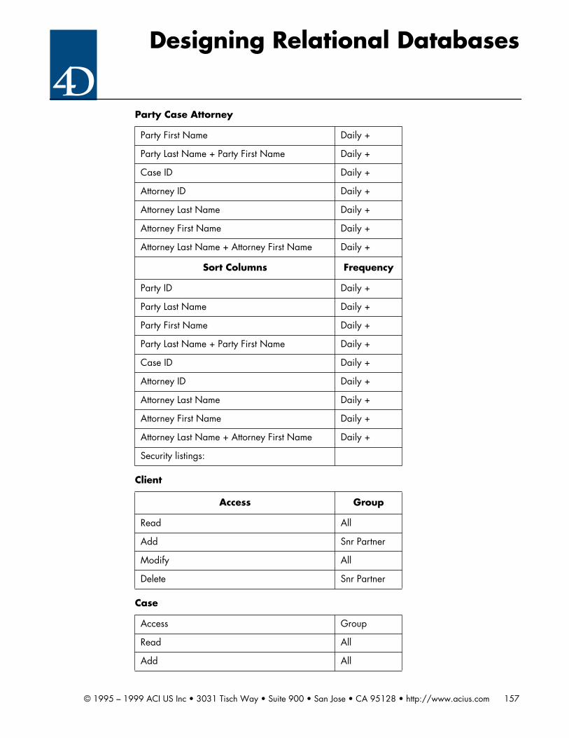
Designing Relational Databases
Party First Name Daily +
Party Last Name + Party First Name Daily +
Case ID Daily +
Attorney ID Daily +
Attorney Last Name Daily +
Attorney First Name Daily +
Attorney Last Name + Attorney First Name Daily +
Sort Columns Frequency
Party ID Daily +
Party Last Name Daily +
Party First Name Daily +
Party Last Name + Party First Name Daily +
Case ID Daily +
Attorney ID Daily +
Attorney Last Name Daily +
Attorney First Name Daily +
Attorney Last Name + Attorney First Name Daily +
Security listings:
Client
Access Group
Read All
Add Snr Partner
Modify All
Delete Snr Partner
Case
Access Group
Read All
Add All
Party Case Attorney
© 1995 – 1999 ACI US Inc • 3031 Tisch Way • Suite 900 • San Jose • CA 95128 • http://www.acius.com 157

Designing Relational Databases
Modify All
Delete Snr Partner
Client Case
Access Group
Read All
Add All
Modify All
Delete Snr Partner
Advertiser
Access Group
Read All
Add Snr Partner
Modify Snr Partner
Delete Snr Partner
Ads
Access Group
Read All
Add All
Modify Snr Partner
Delete Snr Partner
Physicians
Access Group
Read All
Add Snr Partner
Modify Snr Partner
Delete Snr Partner
Case
© 1995 – 1999 ACI US Inc • 3031 Tisch Way • Suite 900 • San Jose • CA 95128 • http://www.acius.com 158

Designing Relational Databases
Party
Access Group
Read All
Add All
Modify All
Delete Snr Partner
Party Case Attorney
Access Group
Read All
Add All
Modify Snr Partner
Delete Snr Partner
© 1995 – 1999 ACI US Inc • 3031 Tisch Way • Suite 900 • San Jose • CA 95128 • http://www.acius.com 159

Designing Relational Databases
Chapter 10 exercises
Exercise 10.1
Products
Column Names Data Types Keys
Part Number String (10) PK
Title String (30)
Price Real
Year Integer
Category String (15)
Customers
Column Names Data Types Keys
Company Name String (25) PK
Contact First Name String (10)
Contact Last Name String (20)
Address String (25)
City String (20)
State String (2)
Zip String (10)
Phone String (10)
Preferred Boolean
Invoices
Column Names Data Types Keys
Invoice Number Longint PK
Invoice Company Name String (25) FK1
Invoice Date Date
Invoice Total Real
Paid Boolean
Payment Method String (15)
© 1995 – 1999 ACI US Inc • 3031 Tisch Way • Suite 900 • San Jose • CA 95128 • http://www.acius.com 160

Designing Relational Databases
Here is the ERD:
Line Items
Column Names Data Types Keys
LI Invoice Number Longint PK1 FK1
LI Part Number String (10) PK2 FK2
Quantity Ordered Integer
Line Items Price Real
Extended Price Real
Line Items
ProductsInvoices
M M
1Belong on
Belong to1
CustomersM1
Generate
© 1995 – 1999 ACI US Inc • 3031 Tisch Way • Suite 900 • San Jose • CA 95128 • http://www.acius.com 161

Designing Relational Databases
Exercise 10.2
Products
Column Names Data Types Keys
Part Number String (10) PK
Title String (30)
Selling Price Real
Year Integer
Quantity Longint
Customers
Column Names Data Types Keys
First Name String (25) PK
Last Name String (10)
Company Name String (20)
Address Text
City String (20)
State String (2)
Zip String (10)
Phone String (10)
Preferred Boolean
Taxable Boolean
Tax ID Number String (20)
Invoices
Column Names Data Types Keys
Invoice Number Longint PK
Invoice Company Name String (25) FK1
Invoice Date Date
Subtotal Real
Sales Tax Real
Grand Total Real
© 1995 – 1999 ACI US Inc • 3031 Tisch Way • Suite 900 • San Jose • CA 95128 • http://www.acius.com 162

Designing Relational Databases
Here is the ERD:
Payment Due Date Date
Paid Boolean
Payment Method String (15)
Comment Text
Invoices
Line Items
ProductsInvoices
M M
1Belong on
Belong to1
CustomersM1
Generate
© 1995 – 1999 ACI US Inc • 3031 Tisch Way • Suite 900 • San Jose • CA 95128 • http://www.acius.com 163

Designing Relational Databases
Chapter 11 exercises
Exercise 11.1
Exercise 11.2
© 1995 – 1999 ACI US Inc • 3031 Tisch Way • Suite 900 • San Jose • CA 95128 • http://www.acius.com 164

Designing Relational Databases
Exercise 11.3
Exercise 11.4
Chapter 12 exercises
Exercise 12.1
A solution to this exercise is included in 4D format on your handout disk. There are
© 1995 – 1999 ACI US Inc • 3031 Tisch Way • Suite 900 • San Jose • CA 95128 • http://www.acius.com 165

Designing Relational Databases
many correct solutions to this problem based upon answers given during the client inter-view process or class discussion. Therefore, no one solution is presented here.
© 1995 – 1999 ACI US Inc • 3031 Tisch Way • Suite 900 • San Jose • CA 95128 • http://www.acius.com 166