Embed Size (px)
Citation preview

BIBLIOTHEK DER TECHNIK / VERLAG MODERNE INDUSTRIE
DESIGNING WITH PTFE
Material, Design Criteria, Processing, System Solutions
Dr. Michael Schlipf / Martin Schuster
1
INTRODUCTION
Polytetrafluorethylene (PTFE) was first discovered by the 27-year-
old Roy Plunkett (1910 - 1994) on 6 April 1938 while he was
experimenting on new cooling agents for DuPont in their Jackson
Laboratory in Deepwater, New Jersey (USA). Plunkett was faced with
the problem that, despite unaltered weight, no gas escaped from
the valve of compressed gas cylinders filled with tetrafluorethylene
(TFE). When searching for the cause, he finally discovered a white
granulate in the gas cylinder: PTFE into which the TFE gas had
obviously spontaneously polymerized itself overnight. When
investigating this granulate, Plunkett immediately realized that it
had a highly unusual behavior. Since it neither reacted with the
offered substances nor dissolved in any other medium - not even in
the most aggressive acids -, the new product was unusable for
chemical reactions. However, during extensive research in the
plastics laboratory, the potential of this new class of plastics was
quickly realized.
As so often happens with new products, PTFE was first of all used for
military applications: as a sealing material in the preparation process
for the production of uranium 235, it resisted the most aggressive
acids. Due to its excellent insulation properties in connection with
minimal damping values, it was used for high-frequency cable
insulation for radar systems. The lack of suitable processing
techniques and the fact that PTFE did not adhere to anything went
firstly against a broader use of the material. Later, between 1955
and 1960, the material slowly began to be used as a non-stick
coating for household goods, e.g. frying pans.
It was only after new techniques in processing plastics were
developed that the foundation stone for industrial applications was
laid. More recently the unique construction material PTFE (Figure 1)
can increasingly be found in objects of daily use such as the mobile

2
phone. Its advantageous properties can be targeted to the
corresponding requirements of the different end usage.
Figure 1: Molecular structure of PTFE
This book aims to show designers and users the unusual versatility
of the special class of plastics. First of all, as well as the usual PTFE
materials, the new meltprocessable PTFE will be described. Design
criteria and processing techniques as well as special PTFE products
cover the spectrum to industrial applications. Case studies and
engineering solutions from many sectors emphatically show the
potential of the design material PTFE. The preconditions for legal
approval for the use of PTFE are also explained in detail.
3
PTFE MATERIALS AND PRE-PRODUCTS
PTFE is characterized by its special properties which set it apart from
all other plastics. This chapter will explain the molecular basis of
PTFE and its influence on production, processing and applications.
PTFE materials can be divided as follows:
− standard PTFE
− modified PTFE
− PTFE compounds
− meltprocessable PTFE
Standard PTFE
Polytetrafluorethylene (PTFE) is still one of the most important
representatives of fully fluorinated (perfluorinated) polymers from
the class of polyhalogenolefins. The carbon chain is nearly
completely shielded by fluorine atoms (Figure 1) and thus protected
from external influences. The carbon-fluorine connection is one of
the strongest bondings in organic chemistry (dissociation energy
460kJ/mol). This results in the unusually high chemical resistance
and thermal durability of PTFE. The melting temperature is 327oC.
PTFE is produced industrially by the polymerization of the monomer
tetrafluorethylene (TFE) (page 19 ff). Depending on whether the
polymerization is carried out in suspension or emulsion, the
resulting product is described as either suspension PTFE or emulsion
PTFE. Although it is basically a thermoplastic, PTFE cannot be
processed by a thermoplastic technique. Due to the very high
molecular weight of up to 108g/mol, the viscosity of the molten
material would be too high.

4
The processing of suspension PTFE - also called pressed powder -
calls for special press and sinter techniques which are very similar to
the processing of sintered ceramics (page 29 ff). The powder is
firstly pressed under a high pressure then sintered to melt the
individual particles whereby the material still maintains its actual
consistency. Finally the sintered product is transformed into the end
product through a machining process. Emulsion PTFE - also called
fine powder or paste-PTFE powder - is processed by paste extrusion
i.e. quasi thermoplastic processing at room temperature. The basic
profile from this process then receives its final properties in a
subsequent sintering process. Corresponding to this special
processing technique, the fields of application for emulsion PTFE
and fluorothermoplastics overlap e.g. in coatings for wires and
cables and for hoses and tubing.
Unsintered PTFE has a high degree of crystallization of 90 to 95 % .
After one sintering, the degree of crystallization is in the range of 50
to 75 %. PTFE has two relaxation temperatures, one at 190C and the
other at 280C (Figure 2). The transformation of the structure is
manifested by a volatile change in the expansion coefficients. These
can specifically influence the properties of the powdered form
material suspension PTFE and the dimensional stability of the end
product. Therefore special attention should be paid to them.
5
Figure 2: phase Figure of PTFE
A temperature between the two relaxation temperatures is
therefore recommended for processing suspension PTFE, e.g.
between 210 and 25
0C. If the granulate is required to have
particularly good free-flowing properties, then the powder can also
be processed at lower temperatures e.g. between 120 and 15
0C.
When processing PTFE, each production step before the actual
extrusion, therefore in particular the mixing of fillers (page 13 ff) or
of extrusion aids, should take place at temperatures below 190C.
Only in this way can it be guaranteed that PTFE agglomerate grains
are not compacted too much which would make an equal
distribution of the lubricants difficult or even impossible. In any case
the machining of the sintered product should take place between
the two relaxation temperatures in order to avoid greater
dimensional deviations.
6
The following special physical and chemical properties of unfilled
PTFE can be singled out:
− almost universal chemical resistance
− exceptionally wide thermal application range from -2600C to
+2600C (for a short time also up to +300
0C)
− very good sliding properties
− anti-adhesive behavior
− good electrical properties (dielectric, high-frequency
damping)
− no water absorption (also resistant to hot water vapor)
− non-combustible; LOI › 95
− light and weather resistant
− physiologically harmless (approved for foods by BgVV, EU
and FDA)
The almost universal chemical resistance is the precondition for the
use of PTFE in the chemical industry e.g. for seals, corrosion-
resistant protective coverings against chemical reactions as well as
piping or in the production sectors of fittings and containers. Due to
its extraordinarily wide fields of thermal application, PTFE especially
lends itself to be used e.g. as sealing elements for valves in
refrigeration engineering or in the field of exhaust gas sensors for
combustion engines - especially in the automotive sector. But PTFE
and related fully fluorinated plastics also play a significant role in
environmental protection relating to the desulphurization of flue
gases in power stations when it is important to firstly cool waste air
flows with aggressive high temperature aerosols and then to
neutralize them, thus preventing toxic components escaping into
the environment.
The very good sliding properties and low wear are reasons why PTFE
or PTFE compounds (page 13 ff) can always be used as sealing
materials for dynamic applications when other materials fail.
7
Therefore these materials are state-of the-art technology for seals in
modern high-pressure fuel injection systems or for the low friction
sealing of rotating axles in engines and transmissions. Due to the
intrinsically good sliding properties, lubricants can often be
dispensed with in PTFE applications where there is friction and wear.
This advantage is not only used in the medical sector but also in
filling plants for drinks, milk and yoghurt as an oily after-taste in
foods is highly undesirable. The physiological harmlessness of PTFE
is one of the essential preconditions for its application in medical
technology or the foods industry.
The excellent electrical properties of PTFE - high relative dielectric
constant and low high frequency damping - are used for printed
circuit boards (PCB) in mobile phones or in insulation for cables,
especially high frequency cables. The strong water-repellent
behavior of PTFE means that these properties remain throughout
the whole lifespan of the product. The absorption of moisture from
the ambient area, a disadvantageous property of nearly all other
plastics, is almost completely eliminated. The non-combustibility of
PTFE, which is free of additives, is an additional safety factor in
electrical applications.
Unfilled PTFE, however, also has some disadvantages which include:
− cold flow
− relatively low wear resistance
− low resistance to high-energy radiation
− pour adhesion
− non-applicability of thermoplastic processing techniques
− can only be welded with the addition of a welding medium
e.g. PFA

8
Modified PTFE
By copolymerizing TFE with a low amount of the also perfluorinated
modifier perfluoropropylvinylether (PPVE) and reducing the
molecular weight, a copolymere (Figure 3) results, which can be
processed by the usual methods for standard PTFE. This new
polymer exhibits the typically positive properties of PTFE and in
addition has the following advantages:
− cold flow reduced by factor 3
− permeation by chemicals and gases reduced by up to 50%
− porosity reduced by 50%
− minimal tendency to pore forming with stretching
− can be welded according to special methods
Figure 3: molecular structure of modified PTFE
9
Modified PTFE is especially suitable for applications where either the
low permeation rate or the low cold flow is a special advantage. Low
permeation rates are required, for example, for protective coverings
of chemical installations, for the corrosion protection of metal
containers and tubing, for static flange seals or for plastic
constructions in the construction of tubing and apparatus. In order
to improve these plastic constructions, the outside of the containers
and tubing is mostly covered with a GFK or CFK sleeving while the
liner of modified PTFE on the inside assumes the function of a
permeation barrier resistant to strong chemicals.
The low cold flow of modified PTFE is the reason for the varied
applications in the seal sector, especially for static flange seals with
a high surface pressure to ensure the purging certainty even at high
pressures and temperatures. If additional form stability or
dimensional stability are required, as is the case, for example, with
pump housings, then modified PTFE is also the solution to the
problem here.
Large, complex components, especially in the construction of
apparatus, can often not be made in one piece. In these cases the
possibility to weld modified PTFE is often used in order to put
together by welding a system solution made up of several individual
components. Installations for chemical reactions with a total weight
of several hundred kilograms have already been manufactured
according to this method.
PTFE Compounds
The mixing of fillers in PTFE or modified PTFE in order to build
compounds is done for the following reasons:
− reducing the cold flow (increasing the pressure resistance)
− reducing wear
− increasing thermal conductivity (reducing wear rate)

10
− reducing thermal expansion
− achieving electrical conductivity for use in ATEX sectors
− minimizing the friction in applications which cause wear and
friction to protect the mating surface (e.g. abrasion-resistant
seals with aluminium as the mating surface).
The reduction of the cold flow can be achieved, on the one hand, by
mixing fillers but also by altering the PTFE matrix. As well as the cold
flow, however, a number of material properties have also to be
optimized in order to take the broad application spectrum of
compounds into consideration. These include mechanical properties
such as strength, elasticity module, friction coefficient or wear, the
thermal expansion co-efficient, chemical resistance and thermal
conductivity. How these material properties can be optimized by
fillers and/or the polymer matrix can be learned from table 1.
Table 1: Optimizing the properties of PTFE compounds by the
parameters polymer matrix and fillers
The wear resistance of standard PTFE is relatively low. This is the
consequence of very weak inter-molecular van der Waals forces
11
between the perfectly shielded carbon chains of the PTFE molecules
which is therefore non-polar towards the outside. In the crystalline
regions of the material, the molecular chains can be moved due to
friction pressure - similar to graphite layers - against each other
layer by layer. The polymer compound in the amorphous areas is
more stable because of inter-molecular entanglements but this
constitutes only approx. 25 to 50 % of the polymer. An essential
improvement in the wear resistance is achieved by mineral or
metallic fillers such as, for example, carbon, graphite, glass or
carbon fibres and bronze. Newly developed special compounds have
significantly improved friction behavior and a very low tendency to
shrink on the mating surface (Figure 4) even in absolutely oil-free
conditions. This is even the case when the mating surface is
untempered.
Figure 4: long-term wear (100hrs) of unfilled PTFE at high
temperatures in dry applications compared to various compounds:
friction conditions; (v = 4m/s, p = 0.42 N/mm2, T = 1000C, Wear
volume in mm2 after 5 hrs)
The amount of sliding friction of the respective surfaces does not
play a significant role in the abrasion behavior. The wear depends
Mating surface

12
much more on the application conditions: the kind of contact
medium, contact pressure, relative speed, temperature and
lubrication. Since no PTFE compound can fulfil all requirements at
the same time, the best mixture has to be determined for each
individual application.
When determining the wear in experiments, it has to be taken into
consideration that each testing method delivers its own set of data
(Figure 5). A direct comparison of materials is therefore only
possible within each individual testing method or under the same or
similar test conditions. The aim should also be to test as close to
practice as possible. Applications are very often illustrated in the
laboratory on a scale of 1:1. The planning of test runs (DoE) and
their evaluation takes place by using statistical methods. With a
minimum of number of tests it is attempted that the parameter
range is covered in an optimal way and the optimal operating point
is determined as quickly as possible.
Figure 5: in a long-term wear test with the pin-plate method (the
plate can both rotate and oscillate) each test follows as a
simultaneous triple test in order to avoid faulty measurements as
much as possible. Changeable parameters are: speed of the shaft
13
(ω), testing piece contact force (P), mating surfaces, mating surfaces
temperatures (T), test atmosphere
An example of the optimization of a radial shaft seal can be seen in
Figure 6.
Figure 6: influence of radial strength, rpm and friction wear due to
optimizing leak rate of high performance radial shaft seals. Test
conditions: radial shaft seal test bench, oil level, radial middle, thick
lip material is a PTFE special compound, pressure: 0-10 bar
Meltprocessed PTFE
For years researchers have been working towards combining the
excellent properties of PTFE and modified PTFE with the possibility
of thermoplastic processing. Approaches have included the further

14
development of production processes for modified PTFE and also
the use of continuing polymer chemical measures. By combining
these approaches, meltprocessable PTFE was first launched on the
market in 2006. In view of the temperature resistance and the
permanent service temperature, no more drastic compromises are
required as had to be taken into consideration in such processes in
the past. The new product is distinguished as follows:
− customized molding/shaping
− suitable for mass production
− short cycle times
− sprue recycling (economical and considerate use of
resources)
− low operator requirements
− high process reliability and stability
Meltprocessable PTFE allows a new kind of and economical system
solutions and closes a gap in the range of the previously known
perfluorinated PTFE materials (PTFE and modified PTFE) and
fluorothermoplastic products (PFA, MFA, FEP and FEP-G). The basic
data of the new material is shown in table 2. Further advantages
shall be explained in detail below.
15
Table 2: typical properties of meltprocessable PTFE (MoldflonTM
)
Basic properties Value
Bulk density
Test process according to DIN EN ISO 60
1200g/l
Density
Test process according to DIN 53479
Buoyancy procedure
2.160 g/cm3
Melting point
Test process according to DIN EN ISO 3146
3180C
Melting flow index MFR 372/5
Test process according to DIN EN ISO 1133
5 g/(10 min)
Mechanical properties
Tensile strength
Test process according to ASTM D 4894/ DIN
53455 (plate 2mm)
25 MPa
Yield strength
Test process according to ASTM D 4894/ DIN
53455 (plate 2mm)
380%
Yield strength
Test process according to ASTM D 4894/ DIN
53455 (plate 2mm)
14 MPa
Young’s modulus
Test process ISO 12086-2, method 511 (plate
2mm)
230C
500C
1000C
1500C
2000C
460 MPa
420 MPa
210 MPa
170 MPa
80 MPa
Deformation under load
Based on ASTM D 621; 15 MPa, 230C, 100hrs,
permanent deformation
2.4%
Other properties
Poisson ratio 0.4%

16
The new type of polymer composition allows even lower cold flow
values to be set than with modified PTFE compounds (Figure 7).
With meltprocessable PTFE, disadvantages including unlimited
chemical resistance, limited approval for use in contact with foods
or acids or in other critical applications based on fillers can also be
avoided. Additional materials in perfluorinated polymers disturb the
compactness of the polymer matrix and cause increased porosity
and permeation. These disadvantages can also be avoided by the
new meltprocessable PTFE. Regarding chemical resistance, anti-
adhesive properties, ageing resistance and electrical insulation,
meltprocessable PTFE is in no way inferior to classic PTFE.
Figure 7: cold flow on unfilled meltprocessable PTFE (MoldflonTM
)
compared to PTFE, modified PTFE and chosen compounds of these
materials
17
The high temperature resistance of meltprocessable PTFE has not
been reached by any other fluorothermoplastic material which can
be processed by thermoplastic methods. With a melting
temperature of 3150C up to far above 320
0C it significantly sets itself
apart from other fully fluorinated fluorothermoplastic materials
such as, for example, PFA, MFA or FEP. This is also a result of the
new kind of polymer composition. The gap between modified PTFE
on the one hand and PFA, MFA or FEP on the other hand is bridged
to the greatest possible extent (Figure 8).
Figure 8: high temperature resistance of meltprocessable PTFE
(MoldflonTM
)

18
Due to the profile of its properties meltprocessable PTFE is also
suitable for special applications with high thermal, chemical,
electrical or mechanical requirements. In mechanical requirements
the new material can especially prove its superiority under pressure.
Production and Preparation of Suspension and
Emulsion PTFE
The following explains how the process of suspension
polymerization and emulsion polymerization is technically
implemented and what preparation processes can be used in order
to produce suspension PTFE and emulsion PTFE to further produce
the required pre-products.
In the case of suspension polymerization the monomer TFE is
transformed into a high-polymer pre-product in a polymerization
reactor with water as the reactant. In the radical polymerization
which takes place in the absence of an emulsifier , a polymerization
level of up to 106 and thus a molecular weight of 10
8g/mol can be
reached. The raw polymerizate is then ground by a grinder under
water flow. Then the reactant water is separated in a process
consisting of several steps. The production is then finished by finely
grinding to a medium-sized grain of between 15 to 50 µm. This
typically takes place in an air-jet grinder. The material obtained after
this process either comes onto the market as pourable suspension
PTFE - also called pressed powder - or it is first processed in further
steps with the following processes (Figure 9):
− by means of agglomeration the non-pourable PTFE is
transformed into pourable suspension PTFE with a grain size
of between 200 and 900 µm
− by means of additional thermal treatment of the pourable
suspension PTFE you get pre-sintered suspension PTFE
19
− after adding fillers the non-pourable suspension PTFE is
transformed into non-pourable suspension PTFE compounds
− if the non-pourable suspension PTFE is additionally subject
to an agglomeration process, you get pourable suspension
PTFE.
Figure 9: processing schematic and product range of suspension
In the case of emulsion polymerization, the monomer TFE is also
transformed into a high molecule pre-product through radical
polymerization in a polymerization reactor with water as the
reactant, but with an emulsifier present. The polymer comes in the
form of a watery emulsion whose PTFE particles have a diameter of
between 200 and 280 nm. This emulsion can be prepared according
to several processes (Figure 10):
− If the emulsion is first precipitated, coagulated and then
separated in a multilevel process from the reactant water
and the emulsifier and finally dried, you get a powdery
emulsion PTFE which is also called fine powder or paste
PTFE powder. This material is characterized by its excellent
pouring qualities and be further processed in a paste
extrusion process (page 32 ff).
− If the emulsion is concentrated and the emulsifier required
for the polymerization is then replaced by another non-
fluorite surface-active agent, you get PTFE dispersion. Such

20
dispersions are, for example, for coating frying pans or
temperature-resistant textile weaves.
− By precipitating and drying the dispersion from an emulsion
PTFE specially structured with a low number of molecules,
you get PTFE micro-powder. Such powders are especially
used as additives for plastics or paint as well as to increase
the viscosity of lubricants.
Figure 10: processing schematic and product range of emulsion
polymerization process
21
FROM PRE-PRODUCT TO PRODUCT
Design Criteria
If you categorize fluoropolymers, especially standard PTFE, modified
PTFE, meltprocessable PTFE and the group of fluorothermoplastics
in the total environments of plastics, you immediately recognize the
special position of this product group. Figure 11 presents the PTFE
materials and the fluorothermoplastics regarding their permanent
service temperature and the heat resistance under load in
comparison with other plastics. While fluoropolymers assume a
special position regarding the permanent service temperature due
to their excellent properties, they have disadvantages with regard to
the heat resistance under load. As a result of weaknesses in the
profile of their properties, they can only be used as self-supporting
construction material under certain circumstances. PVDF, which sets
itself apart from the other fluoropolymers due to its mechanical
parameters, is the most likely to be characterized as a construction
material. It is therefore often used in the construction of valves in
the production of full plastic engineering solutions. PVDF is also used
in order to manufacture complete tubing systems for applications in

22
the semi-conductor industry and to produce, store and transport
pure chemicals.
Figure 11: comparison of PTFE and modified PTFE. Meltprocessable
PTFE (MoldflonTM
) and fluoroplastics (FTP) with other plastics
regarding permanent service temperature and heat resistance under
load
Yield Point
In order to characterize mechanical material properties, preferably
values for the tensile strength or the tensile elongation are given.
This kind of product characterization can be suitable for the
production of raw materials but proving the quality consistency of
the product is of no consequence for the design engineer. In order
to explain this fact, Figure 12 shows the stress-strain graph of
modified PTFE. According to this Figure modified PTFE has a tensile
strength of approx. 38 N/mm2 and a strain at break of approx. 600
%. For the design of plastic components it is not the value of the
failure of the plastic which is decisive but, taking into account the
softness of the fluoropolymers, those values where the plastic
23
begins to change its properties. In the given example these values
are defined by the yield point, which means the point in the stress-
strain graph when the material begins to flow. The characteristic
parameters for the yield strength for modified PTFE only amount to
approx. 14 N/mm2 and the strain at yield of approx.. 25 %. The
designer has to base the design of the components on these values.
Figure 12: stress-strain graph of modified PTFE
Chemical Resistance
Apart from high constant service temperatures, full fluorinated
representatives of the fluoropolymer group are characterized by
excellent chemical resistance. While for plastics in general, reliability
lists comparing a number of aggressive media or solvents are used
to describe chemical properties, the opposite way is followed for full
fluorinated fluoropolymers. As an almost universal chemical
resistance is presumed, only exceptions are noted and these are
then used to characterize resistance (table 3).

24
Table 3: fluoropolymers are characterized by a nearly universal
chemical resistance with only few exceptions.
Cause Effect
Fluorinated hydrocarbons Swelling, reversible after short-
term exposure, irreversible after
longer contact
Alkaline metals, dissolved or
melted
Elimination of fluoride and
polymer destruction
Halogene, elementary fluoride
and chlorine trifluoride
At high temperatures sometimes
strong chemical reaction and
material degradation
Nitrosulphuric acid (mixture of
concentrated sulphuric and
nitric acids)
Above 1000C slow material
decomposition, carbonation
Monomers: incl. styrene,
butadiene and acrylonitrile
Penetrating possible. In the case
of spontaneous polymerization,
swelling or polymer degradation:
popcorn effect
Ionizing rays (gamma and beta
rays)
A ray dose of 10 kGy can reduce
strength by more than 50%
Permeation
In practical experience it can sometimes happen that a engineering
solution using a full fluorinated fluoropolymer does not work to
complete satisfaction although the construction material used is
consistent from the chemical point of view. The cause of this
problem in those cases is often permeation. In this process a
chemical or solvent penetrates the fluoropolymer or even saturates
it without attacking the material. From a scientific point of view
25
permeation is understood as the product of diffusion and solubility
(Figure 13).
Figure 13: permeation: effect of diffusion and solubility
Due to the Brownian molecular movement chemicals spread in all
directions after they have permeated a material and according to
certain principles. This process is described as diffusion. The lower
the boiling point of a chemical or the relevant solvent is, the more
the diffusion is noticeable.
The solubility of a substance in a plastic is basically determined by its
chemical similarity to the matrix material. The more similar the
substance and the chemical are, the more critical is the solubility.
The chemical similarity is, for example, the reason why
chlorofluorocarbon (FCKW) is a suitable solvent in order to swell
fluoropolymers. This swelling effect can be reversible if there is
short-term exposure, but it can lead to a system failure in the case
of a longer reaction time.
What possibilities does the user then have to prevent problems
related to permeation if it is not possible to at least minimize them?
Factors which influence the reduction of permeation are:

26
− The use of modified PTFE instead of standard PTFE; in an
ideal case this can result in an approx. 50% reduction in
permeation.
− Increasing the layer thickness: permeation and layer
thickness behave inversely proportional.
− Reducing the operation temperature: by lowering the
temperature by 12 to 150C, the permeation rate can be
halved.
A typical application where permeation cannot be completely
prevented even by implementing the above-mentioned measures is
the corrosion protection of chemical processes against aggressive
hydrogen chloride gas at high temperatures by means of
fluoropolymer coatings. In this case corrosion can present. Figure 14
shows the cross-section of a distillation column which is coated with
a fluoropolymer film. There is no fixed connection between the
fluoropolymer film and the wall of the column, which is why the
construction is also called the “loose shirt housing”. The fixing of the
coating film inside the distillation column is made by crimping and
clamping in the flange area.
27
Figure 14: corrosion protection due to “loose-shirt housing” of a
distillation column with a fluoropolymer film.
Left: due to lack of ventilation, HCI gas enriches itself between the
film and the steel container to such an extent that corrosion occurs
Right: due to ventilation the diffused HCl gas is specifically removed
and corrosion permanently avoided
On the left-hand side the installation is shown without ventilation.
The hydrogen chloride slowly diffuses through the coating film in a
gaseous state and enriches itself in the gap between the coating film
and the steel container. After exceeding the saturation
concentration, condensation (liquidation) occurs and thus provides
all preconditions for corrosion.
On the right-hand side installation is shown with built-in ventilation.
The gaseous hydrogen chloride which slowly diffuses through the
coating film into the gap between is specifically removed so that the
saturation concentration cannot be reached. As an electrolyte as
well as an electro-chemical potential has also to be present for the
corrosion process, corrosion can be avoided by the introduction of
ventilation.
By means of the effective thermal insulation of the whole design,
the corrosion danger can be reduced even further: the higher the
temperature between the coating film and the steel container, the
more unlikely it is that it falls below the dew point of the hydrogen
chloride diffused into the given concentration. In this case, too,
condensation will occur.

28
Standard Processing Techniques
Four different standard techniques are available for processing
suspension PTFE:
− hydraulic pressing
− automatic pressing
− isostatic pressing
− ram extrusion
In the case of hydraulic pressing, the PTFE powder or the compound
produced from it are firstly compressed under a pressing power of
between 120 and 700 bar and, after being removed from the press
mould, sintered in a hot-air oven. This is what gives the end product
its actual rigidity.
In the case of automatic pressing, the dosage of powder in the
mould, the pressing and the ejection of the compressed powder
take place in an automatic process. This process is especially suitable
for parts with a simple geometry but which have to be produced in
high numbers. After the parts are pressed, they are transformed
into the required end product in a subsequent sintering process
(Figure 15).
29
Figure 15: the various press processes for suspension PTFE
Isostatic pressing is special in that various versions have been
further developed especially for processing PTFE. The principle
underlying all versions is that an elastic diaphragm which is pressure
coated with water or a hydraulic liquid compresses the PTFE
powder. The acting pressing power compromises the PTFE powder
from various directions but always with the same pressure. After
being removed from the mold, the isostatic pressed PTFE parts are
transformed into the end product in a subsequent sintering process.
These processing techniques for suspension PTFE described up to
now have one thing in common: the pressing and sintering take
place in two separate, subsequent steps. If these two steps are
concentrated into one step, then we speak about ram extrusion.
In the case of ram extrusion, the PTFE powder is pressed in batches
through a heated tube by means of periodic stamping whereby the
pressing power required for the compressing is generated either by
wall friction or by an additional brake. Various heating zones which
create a temperature profile are installed along the extrusion tube
so that a complete through sintering is guaranteed during the

30
extrusion process. Especially simple geometric parts, for example,
tubes or rods, are produced with the economical ram extrusion
process (Figure 16). A disadvantage could be the comparatively high
internal stress with which is put on the product. This is especially the
case when a subsequent machining process is required in order to
manufacture parts with a high dimensional stability. Table 4 shows
what kind of products are suitable for each process.
Figure 16: ram extrusion: economical production of PTFE semi-
finished products with simple geometry
31
Table 4: powder settings in the case of processing suspension PTFE
Powder
setting
Hydraulic
pressing
Automatic
pressing
Isostatic
pressing
Ram
extrusion
Pourable yes no yes no
Not
pourable
yes yes yes yes
Pre-sintered no no no yes
The processing of emulsion PTFE takes place exclusively with a paste
extrusion process. In this process, the paste PTFE powder is first
mixed with a lubricating agent - in most cases benzine with different
boil fractions are used - and subsequently processed by means of
piston extrusion to semi-finished products such as, for example,
hoses, tubes or strands (Figure 17). The added benzine is first of all
removed from these semi-finished products in a drying step and
then transformed into the end product by sintering - e.g. hoses or
tubes. In order to manufacture stretched paste bands, the extruded
strands are firstly transformed into a film by calendaring and then
dried in a manufacturing process similar to that for hoses or tubes.
The film is then not sintered but transformed into the end product
by stretching at temperatures below the melting point.

32
Figure 17: schematic representation of manufacturing process of
emulsion PTFE
PTFE special Products
Special processing techniques allow the production of porous PTFE,
laminates and new types of compounds. As a result, the original
PTFE properties are extended in different directions and new
applications for PTFE products are opened up.
33
Porous PTFE
By using a special pressing and sintering technique, suspension PTFE
can be processed into porous PTFE. The powder properties are so
attuned to the press power that a statistic pore size distribution is
achieved during the pressing. The choice of process parameters thus
assures that there is also a porous structure after the sintering. The
special product differs basically from non-sintered or partly sintered
porous PTFE which is produced from emulsion PTFE and used for
breathable linings for jackets or gloves to protect against wetness.
The average pore size of fully sintered porous PTFE can be adjusted
within a very broad range of between approx. 1 and 50 µm. Figure18
shows the structure of fully sintered porous PTFE as visible through
a scanning electron microscope.
Figure 18: structure of porous PTFE
One of the essential properties of this material is a very high
mechanical rigidity which enables self-supporting designs. It

34
distinguishes itself positively from alternative products which are
not sintered and therefore mechanically very fragile and often have
to be supported in applications.
Usual parameters to characterize porous PTFE for applications in the
separation of media are air permeability and water column
resistance. Figure 19 shows the representative values for the
parameters for film/sheet thicknesses ranging from 0.1 to 3.0 mm.
Figure 19: air permeability (above) and water column resistance
35
Porous PTFE is eminently suitable for optical applications as it has a
high reflecting power for light rays in ultra-violet, visible and nearly
infra-red wavelength areas (Figure 20).
Figure 20: the reflection spectrum of porous PTFE
Between 300 and 1800 nm, the reflective capability is nearly
constant and thus independent of the wavelength. Typical
applications are Ulbricht integrating spheres to measure diffuse
reflections and scattered transmissions and to characterize light
sources such as, for example, bulbs or light diodes (LED) or to
measure the performance of lasers, laser diodes or light diodes. As
well as that, porous PTFE is used for Lambertian reflectors and
diffusers. These are used, for example, as normal reflectors,
projection screens or detection sensors and light reducers (Figure
21).

36
Figure 21: Ulbricht integrating sphere in porous PTFE
LAMINATES BASED ON PTFE AND MODIFIED
PTFE
By laminates we understand reinforced PTFE which is designed, on
the one hand, from one or several PTFE films or sheets and, on the
other hand, from a substrate. The material layers are connected
firmly with each other. Fabrics, fibres or knitted fabrics can be used
as substrates as well as films. The substrate consists of, for example,
glass, metal, ceramics, an elastomer or high-performance polymer.
The construction of the laminate can consist of two or more layers.
Designs which consist of up to seven layers are not uncommon.
37
Figure 22 shows a film/sheet made of conductible PTFE laminated
with glass fibres. A lamination with carbon fibre fabric would also be
possible to improve the chemical resistance - especially for
applications which come into contact with liquid acids.
Figure 22: laminate with conductible PTFE film
Typical applications are liners in equipment engineering,
components for electric and electronic applications, as well as
diaphragms in pump and sensor engineering or optically permeable
composites for textile architectural projects (Figure 23).

38
Figure 23: structure and application of laminates based on PTFE and
modified PTFE using the example of tank lining
LAMINATES BASED ON STANDARD PTFE ARE
CHARACTERIZED BY THE FOLLOWING PROPERTIES:
− excellent and universal chemical resistance
− very broad temperature applications usually limited in the
upper ranges by the reliability of the adhesive used
− very good anti-adhesive properties
− resistant to deformation and stress cracking
− no embrittlement or ageing
39
When using modified PTFE as a film/sheet, these properties are
further improved by the following:
− thick polymer structures with few pores
− low permeability
− better weldability
ANISOTROPIC PTFE COMPOUNDS
By means of a special process it is possible to produce a PTFE
compound reinforced with carbon fibres (C fibres) with an
anisotropic profile; the carbon fibres are mainly arranged in the X-Y
levels (Figure 24). This new kind of material is produced as plate,
disc or ring as is required. It is characterized by:
− nearly universal chemical resistance
− extremely high tensile strenght
− high pressure resistance
− superior cold flow resistance
− high abrasion resistance
Figure 24: structure of anisotropic PTFE compounds (XYMON)

40
In comparison to unfilled PTFE or typical compounds with carbon or
glass fibre fillers, the performance increase- measured parallel to
fibre direction - is huge (table 5). The very good chemical resistance
of long carbon fibres and the fact that these are closely surrounded
by fluoropolymers lead to the unique resistance which comes very
close to that of pure PTFE. The material can, for example, be used
with liquid acids, hydrochloric acids, phosphoric acids, mineral oils,
tetrahydrofuran and many other media. Typical examples of
applications are valve seals, bearings, valve seats, flat gaskets, pump
impellers, valve components, piston rings and seals in the
automotive industry.
Table 5: properties of anisotropic PTFE compounds compared to
standard PTFE materials (* parallel to fibre direction)
Property XYMON
type 1
XYMON
type 2
PTFE
25%
carbon
PTFE
25%
glass fibre
PTFE
unfilled
Young’s
modulus
10 000
MPa*
5000
MPa*
800
MPa
750
MPa
tensile
strength
60
MPa*
45
MPa*
15
MPa
17
MPa
33
MPa
deformation
under load
< 1% < 2% 4.5% 8.5% 11%
41
CASE STUDIES BASED ON PRACTICAL EXPERIENCE
What system solutions can be realized with products based on
PTFE? Based on the special requirements of each particular
application, this question will be answered with the help of concrete
examples from various sectors. We describe how the problem can
be solved by choosing a suitable material in connection with the
correct product design.
Seals for the automotive Industry
PTFE sliding rings in CVT transmissions
Variable transmissions such as manual transmissions, automatic
transmissions, automated manual transmissions and double clutch
transmissions always present a compromise between driving
dynamics, consumption and driving comfort. The constant variable
transmission ratio of a CVT transmission enables, on the other hand,
the optimal power transfer. The advantages of the system lie in the
high driving comfort, the smooth power transfer, the low fuel
consumption and the very compact design. At the time of writing
this book, CVT transmissions are suitable for engine torque up to
approx. 420 Nm and can thus cover the whole range of engines of
upper middle class vehicles. The following demands are made on the
sealing elements:

42
− service temperature range -40
0C to +120
0C
− pressure load to maximal 60 bar
− axial stroke up to 20.5 mm within 1.3 s
− lifetime at least 3000 hrs
− medium: automatic transmission oil
Figure 25: cross-section of a CVT transmission with red-colored rings
Figure 25 shows the cross-section of a CVT transmission. The core of
the transmission is the variator consisting of two cone disks and an
embracing medium (plate link chain). Due to the smooth changing in
the axial distance between both cone disks, the transmission can
also be regulated smoothly. The link chain transfers the actuated
torque friction. The axial adjustment of the cone disks takes place
hydraulically. PTFE slide rings are used to separate the two hydraulic
chambers (Figure 26). In order to separate the two hydraulic
chambers, PTFE slide rings with elastomer tension are used. The
slide rings have to have very good pressure and wear resistance.
43
Figure 26: PTFE slide ring with o-ring support
Friction-optimized PTFE Shaft Seals for Formula 1
At the beginning of the development of shaft seals for the
crankshaft of a Formula 1 engine, the aim was to develop a product
that was well sealed, had very low engine friction and was up to the
enormous demands of Formula 1. The technical requirements
included:
− resistance in the face of high-tech synthetic oils
− bridging a short-term lack of lubrication in the sealing area
− leak tight up to 19,000 U/min - for a crankshaft diameter of
55 mm this corresponds to circumferential speed of up to
56 m/s
− lifespan over one single race of approx. 20 hours
First of all a flexible standard shaft seal with a dust lip was tested
because due to its special construction it is suitable for high
circumferential speeds of up to approx. 30 m/s. Tests showed that
standard shaft seals were up to this task. After simulating several
races on the engine test bench, no noticeable wear could be

44
discovered and thus the shaft seal met the leakage requirements
made by formula 1. After this positive experience in testing this
standard shaft seal, the requirements were modified. The aim was
to reduce the weight and to use a lighter housing instead of the
stainless steel housing made of V2A. In addition the friction loss was
further reduced and the external measurements of the shaft seal
adjusted to the housing.
The shaft seal (Figure 27) is now completely and solidly made out of
PTFE. Thus the sealing lip is always exactly concentric - deviations
resulting from assembling cannot happen. The housing form of the
shaft seal is so designed that the sealing lip is specifically lubricated
with oil and the shaft seal can be built into the crankshaft housing
optimally and using the least space. An O-ring provides the static
sealing. An increase of lifespan expectancy to two race weekends or
a maximum of 100 hours is no problem with this shaft seal.
Figure 27: shaft seal for the crankshaft in a Formula 1 engine
45
PTFE Seals in direct-injection Gasoline Systems
In Otto engines with direct-injection gasoline systems, the air-fuel
mix is formed directly in the combustion chambers. Only the air
required for the combustion streams through the intake valve; the
fuel is lead directly into the combustion chamber with a high-
pressure injection valve. This preparation of the fuel-air mixture
increases the engine performance, enables lower fuel consumption
and results in lower toxic emissions.
Fuel pressures of up to 200 bar are achieved with the new direct-
injection gasoline systems by means of a central high-pressure
pump. The compromised fuel is lead directly to the high-pressure
fuel injection valve. This fuel injection valve doses and atomizes the
fuel in the combustion chambers in a very short time. PTFE gaskets
are used both in the high-pressure pump (Figure 28) as well as in
the high-pressure fuel injection valves.
Figure 28: test bench for seals in direct-injection gasoline systems

46
Piston pumps are often used as high-pressure pumps and their
pistons are driven by the camshaft. This makes the following
demands on the sealing elements:
− high wear resistance in order to endure the high, axial
piston speeds of up to 3 m/s
− high pressure stability with pressure pulsations up to an
amplitude of 24 bar in sealing area
− broad service temperature range of between -400C up to
+1500C typical in automotive construction
− very good sliding properties in order to avoid friction
− special sealing geometry for the separation of fuel and
engine oil
− chemical resistance with all commercially available fuels and
engine oils.
Due to the extreme demands mentioned above, only sealing
materials which are very wear resistant, pressure stable and
temperature stable come into question. In first development stages,
pressed pieces (pressed powder type) were used. Changing to
extruded rods with sufficient pressure stability simplified
manufacturing significantly (Figure 29). PTFE as basic material brings
chemical stability and good sliding properties and different
combinations of organic fillers provide wear resistance and pressure
stability.
47
Figure 29: PTFE deformation comparisons of different manufacturing
procedures;
test parameters:
pressure 5N/mm2
test temperatures: 230C, 100
0C, 150
0C
test time: 24 hrs
test piece measurements: 11.2 x 2 mm
As the seals in high-pressure piston pumps additionally have to
separate the media fuel and engine oil, special requirements are
made on the design and geometry of the seal. Double effect sealing
systems are used. On the fuel side, PTFE sealing lips are supported
by stainless steel spring elements in order to guarantee that the
contact pressure of the sealing lips on the pistons remains constant
in the whole service temperature range. On the engine oil side,
sealing lips with memory effect are used - PTFE compounds can be
equipped with a memory function. The sealing lips on the engine oil
side are so formed in thermal processes that radial contact pressure

48
is generated on the mating surface. In this way both media are
reliably separated from each other. The spring-energised seals
available in various geometrical variations and made of high wear
resistant PTFE compounds enable a secure sealing of the high-
pressure piston pumps over a very long lifespan of more than 4000
hours of automotive operation.
PTFE Seals in Pneumatic Spring Compressors
Pneumatic spring compressors are used in pneumatic springs or in
automatic level control systems in middle or upper class passenger
cars but also in light commercial vehicles and SUVs in order to
produce the required compressed air. The pneumatic spring has the
task of increasing driving comfort. Moreover the level of the car can
be lowered at high speed in order to improve road holding and
therefore provide more safety. Especially for station wagons and
light commercial vehicles, the automatic level control results in a
constant vehicle construction level and thus for constant suspension
levels even with high loads. This significantly improves the
driveability of the vehicle.
Vehicle manufacturers make the following demands on the sealing
elements for pneumatic spring seals:
− compression pressure up to maximum 20 bar
− temperature resistant from -40oC to +200
0C
− lifespan of 1000 hrs
− able to operate in dry applications
A difference is made between wobble compressors and
reciprocating compressors. In wobble compressors the piston
(Figure 30) makes a wobbling motion of maximum 90 in the cylinder.
Special gas-tight, round piston rings or memory packs are used here.
49
These have the task of ensuring the sealing of the compressor
chamber from the crank chamber so that the necessary pressure can
be produced in the compressor. In this application it is a single-step
compressor which means that the air is compressed to the required
pressure of maximum 20 bar in one step.
Figure 30: reciprocating compressor solution for compressors in
automotive industry
In the case of reciprocating compressors the piston makes a linear
movement in the cylinder. Special gas-tight piston rings and memory
packs are used here. A piston ring with a gas-tight thrust is chosen
due to the minimal amount of leakage (Figure 31). In addition the
piston is lead into the cylinder with PTFE guide rings.

50
Figure 31: degree of efficiency of various types of piston ring thrust
Contrary to the wobble compressor, the reciprocating compressor in
this application is a two-step compressor. In the first step the air is
compressed at a pressure of between 4 and 6 bar. This compressed
air goes straight into the second step when the end pressure of
maximum 20 bar is reached.
Due to the compression, the sealing elements in both systems heat
up to a temperature of up to 2000C at high pressure. This alone is a
huge challenge for the material. Even at -400C and at an altitude of
4000 metres the compressor has to have the required pressure
available within a given time. If the time limit is exceeded, a fault is
displayed in the vehicle and this would mean an unscheduled trip to
the garage. Thanks to the specially designed PTFE high-performance
materials, these demands can be met.
51
Sensor Technology for the Automotive Industry
PTFE Components in Lambda-Sensors in Exhaust Gas Catalytic
Convertors
In order to minimize toxic emissions from Otto engines, the most
accurate preparation of the air-fuel mix is required. This can only be
achieved if the exhaust gas composition is measured constantly and
the fuel supply adjusted according to the result measured. The
Lambda sensor is the most important measuring sensor in the
regulating loop for the catalytic exhaust gas cleansing. Installed in
the exhaust manifold or the collection pipe, it gives information on
whether the air-fuel mix has to be adjusted to be richer (higher
proportion of fuel) or leaner (higher proportion of air). This provides
the continuous optimal combustion of the air-fuel mix.
The most common construction of Lambda sensor is the Nernst
sensor. The core is formed by a ceramic element which has one side
in the exhaust gas flow and the other side is in contact with external
air. The oxygen concentration is therefore different on both sides of
the ceramic element. Due to the special properties of ceramic, an
electrical voltage is detected in the sensor which depends on the
concentration difference defined according to the Nernst equation.
Depending on the measured sensor voltage, the mix preparation is
adjusted constantly and correspondingly.
Due to the extremely high temperatures in the ceramic element of
up to 3000C, high-temperature resistant plastics are needed for the
cable routeing (grommets) and protective tube (blow molded).
(Figure 32)

52
Figure 32: blow molded tube with grommet in a lambda sensor
PTFE offers the ideal preconditions for this application such as, for
example:
− high temperature resistance, short-term up to 3000C
(Figure 30)
− very good chemical resistance against exhaust gas particles
− very good electrical insulating properties
− high form stability during pressure on the PTFE grommets
for cable routeing and insulation
− high flex-life of the PTFE form hose
53
Figure 33: range of temperature applications for PTFE compared
with other plastics
PTFE grommets are used for cable routeing and cable insulation in
the lambda sensor. They serve as electrical insulators and at the
same time as sealing elements against the atmosphere.
Dimensionally stable PTFE glass fibre compounds are very often
used because, on the one hand, they insulate very well and, on the
other hand, they retain their shape under temperature stress. PTFE
form hoses are used to prevent cable kink and as a sealing against
external influences such as, for example, water spray, cold cleaners
and engine oil. They are manufactured by means of a special blow
molding process. A PTFE tube manufactured by paste extrusion and
molded into a blow molded tube by special tool. Both components
Constant service temperature in 0C

54
are together extremely important in order to protect the lambda
sensor from kinking, to guarantee temperature resistance from the
catalytic convertor and the leak tightness of the Lambda sensor.
PTFE Protective Caps for Steering Angle Sensors
Modern electronics and steering angle sensors enable various
calibrations of electric and electro-hydraulic power-assisted steering
systems. In its basic function the steering angle sensor determines
the angle position of the steering wheel without making contact and
thus also the steering angle of the wheels.
New steering systems, such as, for example, active steering, provide
optimised steering and driving and the stabilization of the vehicle.
The steering transmission is designed variably, that means at lower
driving speeds the vehicle reacts directly to the steering movement
but increasingly indirectly as speed increases. Thus together with an
electronic stability program (ESP) over-steering tendencies are
recognized and the vehicle is stabilized by automatic counter-
steering.
Steering angle sensors require a protective cap especially when the
sensor is directly coupled with the steering gear. The protective cap
has to fulfil the following requirements:
− protect the sensor electronics against steering gear oil
− diffusion tightness against steam and steering gear oil
− temperature resistance from -400C up to +150
0C
− low dynamic friction coefficient as a magnet makes a swing
movement over the protective cap
− connection possibilities with sprayable silicon or pouring
materials
55
In the application described here a PTFE protective cap made of an
special diffusion resistant PTFE material is used (Figure 34). Its
contours are manufactured in a PTFE form molding process. In this
process a PTFE film is heated and molded into a form under heat
and under pressure. In this way nearly every contour can be
manufactured with little material waste and economically. In order
to enable a connection possibility to the injection material - e.g.
silicon - the inner contours of the PTFE protective cap are roughened
in a plasma process, so to say, etched. Only in this way can the anti-
adhesive PTFE be connected to other materials. This described
manufacturing process of form molding techniques and using special
PTFE basic materials enable the special requirements of the
automotive industry to be met economically.
Figure 34: steering angle sensor with mounted protective cap

56
Diaphragms for the Pump and Valve Industries
Diaphragms are hermetic seals between two areas which usually
contain different media and/or are under different pressures. As
opposed to piston seals and rod seals, no delay leakage occurs on
the diaphragm. Low demands are made on the tolerances and
surfaces of neighbouring parts.
The form diaphragm described as follows has to meet the following
demands in the filing valve of a bottling plant (Figure 35):
− good flex-life
− nearly universal chemical resistance
− very easy to sterilize
− temperature resistant from -600C to +200
0C
− FDA-approved material
− high flexibility
− lowest diffusion
Figure 35: form diaphragm for bottling plants
57
Up to today a purely elastomeric diaphragm or a PTFE elastomeric
connecting diaphragm are used as form diaphragms in the filling
valve of a bottling plant. The development of a multi-layer
diaphragm is however complex. Due to the complexity of the
manufacturing, deviations in the diaphragm properties which could
lead to a premature failure of the component can occur. Because
special tools are required, such diaphragms are also very expensive.
Special problems occur in filling beer: froth remains stick to the
diaphragm and crystallize. As a result the diaphragm can stick. This
causes very quickly in the elastomeric parts to tear very quickly in
the switching operation. The user is then also confronted with
another weak point: aggressive media can attack the upper surfaces
of the elastomers, despite a PTFE coating, because these media
diffuse through the mostly thin films. The layers often separate
themselves from each other anyway in normal operation when, due
to different elasticity modulus (E-module) and shear modulus (G-
module), the materials used result in inhomogeneous tension
distributions which put pressure on the boundary layer. This
characteristic often limits the lifespan of the connecting diaphragm.
Therefore it is sensible to use pure PTFE diaphragms in the food
industry. The mechanical and anti-adhesive properties are
essentially better and the material has FDA approval. The extreme
resistance of PTFE to frequent flexing - this property makes PTFE
the preferred material for diaphragms and is unknown from any
other thermo-plastic material - is a great advantage for applications
such as filling valve diaphragms.
Optimized PTFE material can meet all the required values for
endurance strength. Therefore this material exceeds standard PTFE
3-fold in its endurance strength and modified PTFE even 10-fold
(Figure 36). The advantages of modified PTFE including low
permeation, reduced cold flow and a smoothly machinable surface
remain. The optimal geometry of the PTFE diaphragm depends on

58
the kind of manufacturing - molded or machined. As a result of
optimizing the diaphragm material and the diaphragm geometry,
the filling valve works trouble-free: in practical use a lifetime of over
20 million operating cycles.
Figure 36: flex-lifetest of various qualities of PTFE: a 1 mm thick film
piece (test piece) standardized according to SPI is bent to 900 in both
directions by 4 Hz. If there is a complete break at the flexing point,
the test apparatus stops
Extinguishing Nozzles for High Voltage Switches
The extinguishing and/or quenching nozzles of high voltage switches
are a decisive component in circuit breaker units. The quenching gas
(SF6) streaming out of the control chamber is lead into it and then
blown into the upper switch area. When the voltage switch is
Flexing cycles (Mio)
59
separated, an electric arc occurs on the circuit voltage which is
quenched with the help of the gas.
The PTFE extinguishing nozzle illustrated in Figure 37 consist of a
PTFE compound which is totally resistant to chemicals (acids,
alkalis), temperature resistant up to 2600C in constant operation
(short-term up to 3000C), incombustible and - very important for use
in the switch - an excellent insulator.
Figure 37: extinguishing nozzles (left) in various switch positions:
when switching (middle), a high arc erosion resistance is required
due to the high thermal and mechanical demands. In switch position
“off”, the dielectric demands are high.
A special filler is added to the PTFE which is decisive for the switch-
off capacity, the lifespan of the switch and in addition, the coloring
of the jet. The composition of this filler is a heavily guarded secret of
each switch manufacturer. In order to minimize material wear, test
on switch procedure off
switch position

60
pieces are pressed isostatically, sintered and finally turned / milled
into the final form (Figure 38).
Figure 38: extinguishing nozzle for high-frequency switches
Special Products for medical Technology and
chemical Analysis
PTFE tubing for flexible endoscopes
In medical technology precision tubes are mainly used in the field of
endoscopy e.g. in catheters to extract gallstones. It is possible to
extrude PTFE tubing with several channels (Figure 39).
61
Figure 39: 3-lumen tubing
Such multi-lumen tubing can therefore take over more than one
function. This means not only that processes can be more user-
friendly but also that the assembly is easier as individual
components can often be dispensed with.
Above all in bronchoscopes is tubing with tapering (Figure 40) used
more and more as this enables even deeper penetration into
damaged areas.
Figure 40: tubing with tapering

62
Very advanced constrictions of the respiratory tract can thus be
passed through better and tumours or lymphomas can be treated
specifically. Colored markings on the tubing help to be able to define
corresponding working areas and /or positions (Figure 41). In
addition this technology is often used to put markings or letterings
on the tubing according to customer specifications. For X-ray
applications, the PTFE matrix can be altered by mixing contrastable
additives so that a color coding of the tubing is easily recognizable.
Figure 41: color-coded tubing with X-ray contrast capability
Above all in the medical sector the surface qualities of the tubing
play an important role. High demands are made on the adhesive
technology when connecting systems or metal or ceramic bushings
have to be connected with the tubing. Such connecting systems
often require a long-term durability regarding the adhesive strength.
In order to create such a stable connection with PTFE, a modification
of PTFE is required. The aim in this case is to increase the surface
63
energy so that surface wetting can take place. The processes used
for this are wet etching or dry plasma etching. Further demands
made on the tubing are:
− biocompatibility
− UV resistance
− high wear hardness
− able to be sterilized
PTFE tubing modules as venting units in liquid
chromatographs
Liquid chromatographs are used in analytics in order to break down
the liquid material mixture to be analyzed into its component parts.
In this case the liquids to be analyzed have to be absolutely free
from dissolved gases. This task is taken over by the venting unit.
In this example the venting of liquids takes place through a tubing
module (Figure 42) which consists of a number of thin PTFE tubes
through which the liquid to be analyzed is fed. PTFE plastic is
permeable for gases. The tubing bundle has a large surface area for
effective venting with a minimal wall thickness. The tubing bundle is
in an evacuating chamber. Due to the difference in pressure, the
dissolved gas particles escape from the liquid to be analyzed
through the walls of the tubing into the chamber and are there
extracted by the pump. The vented liquid to be analyzed is then
further transported to the liquid chromatograph and analyzed.

64
Figure 42: tubing module for liquid chromatograph
The following demands are put on the PTFE tubing modules:
− chemical resistance to nearly all media such as, for example,
acids, alkalis and solvents
− no water absorption allowed
− specific gas permeability of the tubing
− very smooth internal surfaces in order to avoid residue
− FDA approved materials suitable for the food and medical
industries
− high-purity materials so that the measuring results are not
adulterated.
65
Only PTFE meets these demands. In production, in each case several
PTFE tubes are welded in a connector into a tubing bundle.
Couplings at both ends allow the tubing module to be installed
directly. Last but not least the extremely good chemical resistance of
PTFE to nearly all solvents, acids and alkalis predestines this material
for this special application. Venting modules for liquid
chromatographs would not be possible without PTFE tubing
modules.
PTFE sealing gaskets for respiratory air compressors
Small compressors used as respiratory air compressors in medical
applications have to have a low weight, be maintenance free and
long-lasting. A known application in respiratory air therapy is to
produce compressed air in inhalers: the small, light compressors
compress the air to the required pressure which then enables an
effective vaporization of the materials.
In the respiratory air compressor illustrated in Figure 43 it is a radial
piston compressor with a plastic cylinder. Such small compressors
are constructed from only a few components and are nearly
maintenance free. The produced air is pure, oil-free and neutral in
taste.

66
Figure 43: respiratory air compressor with mounted memory packing
(colored red)
The following demands are made on the sealing element of the
respiratory air compressor:
− low friction for low motor current draw since the machine is
partly used in battery operation
− wear resistance for a long lifespan and low abrasion of the
seal and the mating surface
− material with approval for medical applications.
The material used for the sealing element of the illustrated radial
piston compressor is a PTFE compound whose components are non-
toxic/harmless. The sealing element withstands temperatures from -
67
400C to +200
0C, pressure up to 5 bar and a sliding velocity of up to
3m/s.
The memory cup packing is a simple cost-effective construction. The
radial piston can be sealed well with this construction. The sealing
gasket adapts itself to the changing available space which is caused
by the tumbling motion. The radial lip initial tension is achieved by
only one thermal molding process without additional springs. It can
be adapted to the application. The advantages of this seal such as
low wear, low friction, no stick-slip effect and thus low start-up
energy even after a longer standing period make it very suitable for
applications in small compressors.
Figure 44: cross-section of memory cup packing
Reflectors and Diffusers for the optics Industry
Ulbricht integrating spheres are widely used in lighting technology
and in spectroscopy. With internal diameters ranging from a few
centimeters up to three meters, the preferred coating on the
interior side used to be barium sulphate. The reflectors
manufactured in this way have, however, a yellow discoloration over
a period of time, tend to accumulate dirt particles and become
sensitive to mechanical damage. This means that they have to be
regularly recoated.

68
These disadvantages can be avoided if porous PTFE is used as the
reflecting surface. As a result of its nearly perfect Lambertian
behavior, porous PTFE is very well suited for coating the interior
surfaces of Ulbricht integrating spheres. Lambertian behavior means
the ability of a material to reflect projected light in the same
intensity in any direction (Figure 45).
Figure 45: Lambertian reflector
Figure 45: the design of reflectors
General properties of porous PTFE which are suitable for optical
applications are:
− high reflectivity (reflecting degree of >99% in wavelength
range of 400 to 1500nm, >95% in wavelength range of 250
to 2500nm)
− Lambertian behavior in wavelength range of ultra-violet and
visible light as well as in close infrared
− hydrophobic
− thermally stable up to 3000C
Porous PTFE
Reflected light
Projected light ray
69
− nearly universal chemical resistance with only few
exceptions needing consideration
− non combustible; LOI >95%
− flammability according to DIN4102, class A2
− no tendency to age, yellow discoloration or brittleness
(long-term resistance also to ultra-violet rays)
− physical properties adjustable over a wide area (Figure 46)
− possibility to change the color by adding fillers
Figure 46: the design of reflectors based on porous PTFE can be
adapted to the demands of the application
PTFE is extremely suitable as a diffuser for transmitted light in
wavelengths ranging from ultra-violet over visible light to close
infra-red. Typical applications for this are, for example, background
lighting of instruments, screens and display equipment. In order to
create a suitably high light intensity, the typical thicknesses of films
for diffuser applications range between 100 µm and 1 mm. The
transmission degrees under these conditions can be varied within a
very broad range, for example, between 5 and 70%.

70
Rollers and rolls for high performance Printers
High performance printers have both fuser roller systems as well as
feed roll systems. In the following application examples, the use of
PTFE in fuser roller systems is described in more detail.
When fusing, the toner particles have to be melted and firmly fixed
to the print material (e.g. paper or film). Fuser roller systems usually
consist of the heated fuser roller and the pressure roller which
provides the necessary counter pressure. The following demands
are made on such a roller system:
− constant temperatures of 220
0C for melting the toner
− high wear resistance as paper as well as the other materials
which are to be printed are very abrasive
− good thermal conductivity as the radiant heater is in the
roller core
− excellent anti-adhesive behavior as no toner particles should
stick to the roller
Rollers coated with a PTFE film have proved to be the optimal
solution for these high demands (Figure 47). A PTFE film etched with
a special high temperature resistant adhesive is applied to the
aluminium base body with its excellent thermal conductivity. Finally
the PTFE film is ground down to a thickness of 500 to 250 µm.
71
Figure 47: fuser rollers coated with high-performance PTFE
The choice of the PTFE compound as film material is always a
compromise between abrasion resistance, thermal conductivity
(Figure 48) and anti-adhesive properties. The correct coating allows
high performance printers with an average of 1200 sheets per
minute to print up to 10 million sheets without requiring any
maintenance.

72
Figure 48: thermal conductivity of coatings for fuser rollers: TP
thermoplastic (e.g. PPS, PEEK)
Large-sized Shaft Seals for Wind Power Plants
Large machines and plants usually place high demands. This also
applies to sealing elements in wind power plants. The first problem
is in manufacturing the large diameters. As PTFE is a molded,
sintered material, the pressing tools have to be filled with PTFE
powder by hand (Figure 49).
73
Figure 49: a tool to manufacture a ring-formed test piece is filled
with PTFE powder
The maximum external diameter is 3000 mm. This necessitates
large-sized sintering ovens in order to sinter the test pieces. The
seals are then manufactured under tension on a special lathe (Figure
50). As PTFE has a large thermal expansion coefficient, the seals are
measured at defined temperatures of 23 0C. Due to tensions in the
material and temperature fluctuations, there is the danger that the
diameter changes, i.e. usually shrinks. In order to guarantee stable
measurements, for certain applications the rings are stored on a
spike.

74
Figure 50: the finished test piece is processed on a lathe
The radial diameter of the rotary shaft seal for wind power plants as
shown above is 1200 mm and the circumference speed reaches 1.6
m/s.
The seal has to retain the fat application during storage and prevent
the fat from escaping. Further demands are:
− long lifespan
− low friction
− ozone resistant
75
Since it is extremely difficult to disassemble such rotary shaft seals,
the seal is expected to run for many years. A spring energised seal as
illustrated in Figure 51 has proved to be best for this application.
Figure 51: spring-energized seal as rotary shaft seal in wind power
plants
APPROVALS AND GUIDELINES
As well as the technical feasibility of system solutions, the legal
approval of such systems is nowadays of increasing importance. This
is especially true of applications which effect people and their
safety.

76
Approvals for contact with foods
The basic legal requirements on materials or objects which come
into contact with foods are laid down in EU countries by regulations
from the European Commission and national laws. Due to the very
advanced harmonization process within the EU, EU regulations are
increasingly brought to bear on applications in the plastics sector.
The FDA (US Food & Drug Administration) is the most important
regulatory system for food applications in the world. Providers of
components which come into contact with foods should take the
requirements of the EU as well as the FDA into consideration,
independent of the aspired sales market, and, moreover, observe
the specific country specifications.
In Germany the legal stipulations for materials or objects that come
into contact with foods are laid down in the regulation governing
articles of daily use (LMBG). In addition, the plastics
recommendations from the Federal Institute for Consumer Health
Protection and Veterinary Medicine (BgVV), which was dissolved on
01.11.2002, also apply. The newly formed Federal Institute for Risk
Assessment (BfR) has taken over responsibility for the areas food
safety and consumer protection since that date.
Dangers to foods and drinking water especially emanate from the
migration of plastics elements. The following can migrate from virgin
PTFE:
− monomers (e.g. TFE, HFP, PPVE)
− oligomers with low molecular weight
77
As well as the above-mentioned monomers and oligomers, fillers
such as, for example, glass fibres, graphite or E-carbons, can also
migrate from virgin PTFE. The following do not usually migrate from
virgin PTFE:
− additives (not usual in PTFE)
− antioxidants
− lubricants
− plasticizers
− stabilizers (flame-retardant additives, UV absorbers)
Due to its described properties and its special purity, PTFE is
preferred for applications placing the highest demands on the purity
and physiological harmlessness in contact with foods but is also
chosen for applications in the pharmaceutical industry and when
bio-compatibility is required.
Table 6 classifies important PTFE materials for use in contact with
foods corresponding to its principle suitability according to the
regulatory systems LMBG, EU and FDA. The overview is only
intended as information. Concrete approval must be collected from
the manufacturers of the raw materials in each individual case.
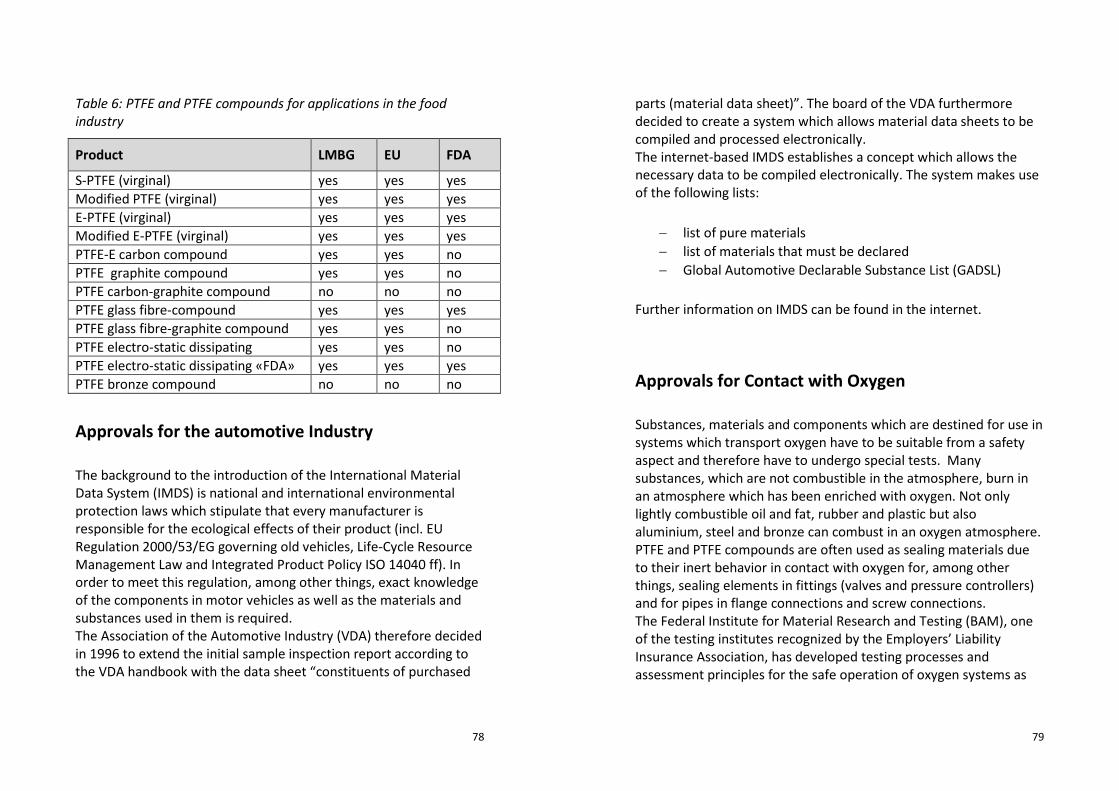
78
Table 6: PTFE and PTFE compounds for applications in the food
industry
Product LMBG EU FDA
S-PTFE (virginal) yes yes yes
Modified PTFE (virginal) yes yes yes
E-PTFE (virginal) yes yes yes
Modified E-PTFE (virginal) yes yes yes
PTFE-E carbon compound yes yes no
PTFE graphite compound yes yes no
PTFE carbon-graphite compound no no no
PTFE glass fibre-compound yes yes yes
PTFE glass fibre-graphite compound yes yes no
PTFE electro-static dissipating yes yes no
PTFE electro-static dissipating «FDA» yes yes yes
PTFE bronze compound no no no
Approvals for the automotive Industry
The background to the introduction of the International Material
Data System (IMDS) is national and international environmental
protection laws which stipulate that every manufacturer is
responsible for the ecological effects of their product (incl. EU
Regulation 2000/53/EG governing old vehicles, Life-Cycle Resource
Management Law and Integrated Product Policy ISO 14040 ff). In
order to meet this regulation, among other things, exact knowledge
of the components in motor vehicles as well as the materials and
substances used in them is required.
The Association of the Automotive Industry (VDA) therefore decided
in 1996 to extend the initial sample inspection report according to
the VDA handbook with the data sheet “constituents of purchased
79
parts (material data sheet)”. The board of the VDA furthermore
decided to create a system which allows material data sheets to be
compiled and processed electronically.
The internet-based IMDS establishes a concept which allows the
necessary data to be compiled electronically. The system makes use
of the following lists:
− list of pure materials
− list of materials that must be declared
− Global Automotive Declarable Substance List (GADSL)
Further information on IMDS can be found in the internet.
Approvals for Contact with Oxygen
Substances, materials and components which are destined for use in
systems which transport oxygen have to be suitable from a safety
aspect and therefore have to undergo special tests. Many
substances, which are not combustible in the atmosphere, burn in
an atmosphere which has been enriched with oxygen. Not only
lightly combustible oil and fat, rubber and plastic but also
aluminium, steel and bronze can combust in an oxygen atmosphere.
PTFE and PTFE compounds are often used as sealing materials due
to their inert behavior in contact with oxygen for, among other
things, sealing elements in fittings (valves and pressure controllers)
and for pipes in flange connections and screw connections.
The Federal Institute for Material Research and Testing (BAM), one
of the testing institutes recognized by the Employers’ Liability
Insurance Association, has developed testing processes and
assessment principles for the safe operation of oxygen systems as

80
well as for non-metallic seals over the past five years. Components
made of PTFE and PTFE compounds for specific applications in
systems transporting oxygen are assessed according to the following
criteria:
− ignition temperature in compressed oxygen
− resistant to ageing in compressed oxygen
− impact of oxygen pressure surges
− testing of flat gaskets for flange connections
− reactivity with liquid oxygen in the case of impact stress
Table 7 gives an incomplete overview of BAM tested sealing
materials made of PTFE and PTFE compounds including the BAM
test procedures used. The results are usually only good as an
orientation. The above-mentioned tests should always be carried
out on the finished components for a final assessment.
81
Table 7: PTFE and PTFE compounds for applications in contact with
oxygen
Product Test procedure BAM
listing
a) b) c) d) e)
S-PTFE (virginal) yes yes yes yes no yes
Modified PTFE (virginal) yes yes yes yes no yes
PTFE glass-fibre compound yes yes yes yes yes yes
PTFE glass-fibre graphite
compound
yes no yes no no yes
PTFE E carbon compound yes yes yes yes no yes
PTFE carbon-graphite
compound
yes yes yes yes no yes
PTFE electro-static dissipating yes yes yes yes no yes
PTFE graphite compound yes yes yes no no yes
PTFE bronze compound yes yes yes yes no yes
PTFE bronze carbon
compound
yes yes yes no no yes
Approvals for explosion endangered Areas
On 01 July 2003 the ATEX directive 94/9/EG came into effect as EN
13436 according to which non-electric appliances have also to
receive approval for use in explosion endangered areas. This
directive stipulates the explosion protection of non-electric systems,
appliances and components in explosion endangered areas and thus
the responsibilities for the manufacturer. It defines an explosion
endangered atmosphere as a “mixture of air and combustible gases,
vapor, mist or dust under atmospheric conditions where the
combustible process is transferred to the whole unburned mixture
after successful combustion”. The ATEX conformity certificate refers
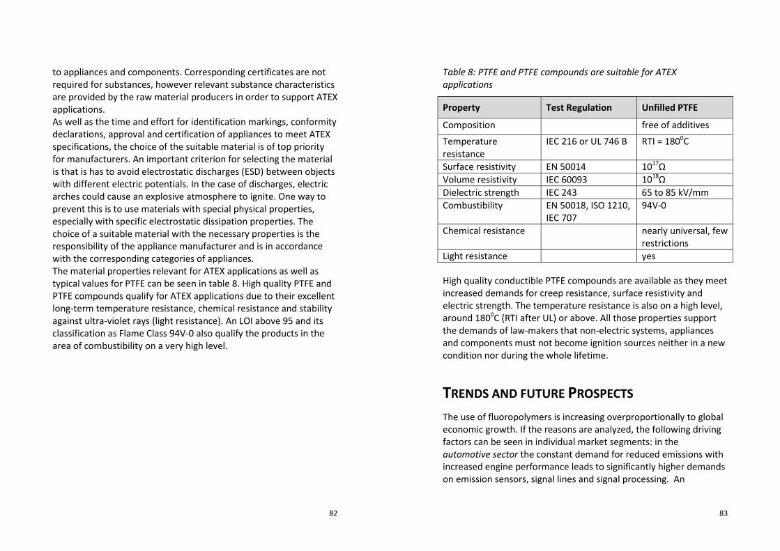
82
to appliances and components. Corresponding certificates are not
required for substances, however relevant substance characteristics
are provided by the raw material producers in order to support ATEX
applications.
As well as the time and effort for identification markings, conformity
declarations, approval and certification of appliances to meet ATEX
specifications, the choice of the suitable material is of top priority
for manufacturers. An important criterion for selecting the material
is that is has to avoid electrostatic discharges (ESD) between objects
with different electric potentials. In the case of discharges, electric
arches could cause an explosive atmosphere to ignite. One way to
prevent this is to use materials with special physical properties,
especially with specific electrostatic dissipation properties. The
choice of a suitable material with the necessary properties is the
responsibility of the appliance manufacturer and is in accordance
with the corresponding categories of appliances.
The material properties relevant for ATEX applications as well as
typical values for PTFE can be seen in table 8. High quality PTFE and
PTFE compounds qualify for ATEX applications due to their excellent
long-term temperature resistance, chemical resistance and stability
against ultra-violet rays (light resistance). An LOI above 95 and its
classification as Flame Class 94V-0 also qualify the products in the
area of combustibility on a very high level.
83
Table 8: PTFE and PTFE compounds are suitable for ATEX
applications
Property Test Regulation Unfilled PTFE
Composition free of additives
Temperature
resistance
IEC 216 or UL 746 B RTI = 1800C
Surface resistivity EN 50014 1017
Ω
Volume resistivity IEC 60093 1018
Ω
Dielectric strength IEC 243 65 to 85 kV/mm
Combustibility EN 50018, ISO 1210,
IEC 707
94V-0
Chemical resistance nearly universal, few
restrictions
Light resistance yes
High quality conductible PTFE compounds are available as they meet
increased demands for creep resistance, surface resistivity and
electric strength. The temperature resistance is also on a high level,
around 1800C (RTI after UL) or above. All those properties support
the demands of law-makers that non-electric systems, appliances
and components must not become ignition sources neither in a new
condition nor during the whole lifetime.
TRENDS AND FUTURE PROSPECTS
The use of fluoropolymers is increasing overproportionally to global
economic growth. If the reasons are analyzed, the following driving
factors can be seen in individual market segments: in the
automotive sector the constant demand for reduced emissions with
increased engine performance leads to significantly higher demands
on emission sensors, signal lines and signal processing. An

84
intelligent use of performance reducing units such as, for example,
for cooling or air conditioning, is strived for. The increasing need for
comfort and additional safety requirements necessitate electronic
load levelling systems or equipping with multiple airbags. Most of
this equipment is directly next to the engine, takes up signals from
this hot area or is in contact with aggressive fuels or lubricants.
Because the required lifespan has tripled in the last 25 years, only
fluoropolymers or compounds based on these are increasingly used.
In the medical sector there is a rapid mechanization and automation
of diagnostics and therapy methods. PTFE is increasingly used
everywhere where high tissue tolerability is required as well as
universal media resistance. High power density in connection with
increasing miniaturization in the electronics sector increasingly
demand materials with better and better insulation and absorption.
The low dielectric constants of PTFE enable always tighter packing
densities of electronic components and low electric loss factors
enable a significant increase in the signal frequency of computer and
broadcasting performances. In the construction of chemical
installations the demand for longer lifespans and the higher
availability of installations lead to an increased use of
fluoropolymers, not only as materials for seals but also increasingly
for whole installations such as reactors or pipe systems made wholly
of plastics. Last but not least fluoropolymers are therefore an
economic alternative to stainless steel.
The introduction of meltprocessable PTFE effectively counteracts
the current main disadvantages of the subsequent machining of
PTFE: while in the case of complex geometries of components, up to
90% waste has often had to be accepted up to now, thanks to
injection molding or extrusion manufacturing, the net yield from
plastics can be increased to nearly 100%. Sprues or remains from
injection molding can be recycled and made into the same or similar
products. All of the mentioned advantages can be applied to
compounds based on meltprocessed PTFE.
85
The increase in lifespan is most effective measure to protect
resources. Good wear and sliding properties are best achieved by
developing compounds based on PTFE, modified PTFE or
meltprocessed PTFE. When modern compounds in addition preserve
counter direction mating surfaces, then, for example, heavy steel
can be exchanged for lighter aluminium - a plus factor which is
especially cost-saving in automotive applications.
TECHNICAL TERMS AND ACRONYMS
amorph structureless configuration of atoms and solid
bodies
ATEX Atmosphères Explosibles
BAM Bundesanstalt für Materialforschung- und
prűfung (Federal Institute for Material Research
and Testing)
BfR Bundesinstitute für Risikobewertung (Federal
Institute of Risk Assessment). Successor to
BgVV
BgVV Bundesinstitute für gesundheitlichen
Verbraucherschutz und Veterinärmedizin
(Federal Institute for Consumer Health
Protection and Veterinary Medicine)
CVT Continuously Variable Transmission
dielectric electrical insulating material in which an
opposing field is built up against the external
electrical field by electrical polarization
DIN Deutsches Institut für Normen e.V. (German

86
Institute for Norms and Standards)
DoE Design of Experiments
E-carbon electro-graphite carbon
EN European Norm
ESD Electronic Static Discharge
FDA Food & Drug Administration
FEP Fluorinated Ethylene Propylene
FEP-G Fluorinated Ethylene Propylene, solvent-based
polymerization process
Flame Class 94V-0 term used within UL 94
FTP Fluorothermoplast
GADSL Global Automotive Declarable Substance List
GFK Glass Fibre reinforced Plastic
HDPE High density Polyethylene
HFP Hexafluoro- propylene
IEC International Electrotechnical Commission
IMDS International Material Data System
ISO International Standard Organization
Cold flow deformation (of PTFE) under load
CFK Carbon Fibre reinforced Plastic
LCP Liquid Chrystal Polymer
LMBG Lebensmittel- und Bedarfsgegenstandgesezt
(law governing foods and articles of daily use)
LOI Limited Oxygen Index
MFA Perfluoro methoxy modified PTFE
monomer basic chemical molecule for polymerization
MVQ silicone rubber
oligomer polymer with low degree of polymerization n,
e.g. n = 2...........12
PA polyamide
PAEK polyaryl ether ketone
PAI polyamide-imide
87
PBT polybutylene terphthalate
PC polycarbonate
PEEK polyetheretherketone
PEI polyetherimide
PES polyether sulphone
PET polyethelene terephthalate
PFA perfluoralkoxy modified PTFE
polymer basic molecule for plastics manufactured by
joining very many single monomers
POM polyoxymethylene
PP polypropylene
PPE polyphenylene ether
PPS polyphenylene sulphide
PPVE perfluoproplyvinylether
PSU polysulphone
PTFE polytetrafluoroethylene
PVDF polyvinylidene fluoride
RTI Relative Temperature Index
SPI Society of Plastics Industry
SUV Sports Utility Vehicle
TFE tetrafluoroethylene
VDA Verband der Automobilindustrie (Association of
the German Automotive Industry)
virginal PTFE unprocessed PTFE powder
UL 94 safety norm of the Underwriters Laboratories
Inc. (UL®) called “Tests for Flammability of
Plastic Materials for Parts in Devices and
Appliances”
UV ultraviolet
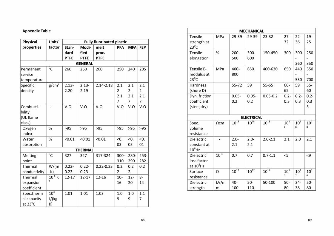
88
Appendix Table
Physical
properties
Unit/
factor
Fully fluorinated plastic
Stan-
dard
PTFE
Modi-
fied
PTFE
melt
proc.
PTFE
PFA MFA FEP
GENERAL
Permanent
service
temperature
0C 260 260 260 250 240 205
Specific
density
g/cm3 2.13-
2.20
2.13-
2.19
2.14-2.18 2.1
2-
2.1
7
2.1
2-
2.1
7
2.1
2-
2.1
7
Combusti-
bility
(UL flame
class)
- V-O V-O V-O V-O V-O V-O
Oxygen
index
% >95 >95 >95 >95 >95 >95
Water
absorption
% <0.01 <0.01 <0.01 <0.
03
<0.
03
<0.
01
THERMAL
Melting
point
0C 327 327 317-324 300-
310
280-
290
253-
282
Thermal
conductivity
W/(m
-K)
0.22-
0.23
0.22-
0.23
0.22-0.23 0.2
2
0.2
2
0.2
Thermal
expansion
coefficient
10-5
K-
1
12-17 12-17 12-16 10-
16
12-
20
8-
14
Spec.therm
al capacity
at 230C
103
J/(kg
K)
1.01 1.01 1.03 1.0
9
1.0
9
1.1
7
89
MECHANICAL
Tensile
strength at
230C
MPa 29-39 29-39 23-32 27-
32
22-
36
19-
25
Tensile
elongation
% 200-
500
300-
600
150-450 300 300
-
360
250
-
350
Tensile E-
modulus at
230C
MPa 400-
800
650 400-630 650 440
-
550
350
-
700
Hardness
(shore D)
55-72 59 55-65 60-
65
59 55-
60
Dyn, friction
coefficient
(steel,dry)
0.05-
0.2
0.05-
0.2
0.05-0.2 0.2-
0.3
0.2-
0.3
0.2-
0.3
5
ELECTRICAL
Spec.
volume
resistance
Ωcm 1018
1018
1018
101
8
101
8
101
8
Dielectric
constant at
106Hz
- 2.0-
2.1
2.0-
2.1
2.0-2.1 2.1 2.0 2.1
Dielectric
loss factor
at 106Hz
10-4
0.7 0.7 0.7-1.1 <5 <9
Surface
resistance
Ω 1017
1017
1017
101
7
101
7
101
6
Dielectric
strength
kV/m
m
40-
100
50-
110
50-100 50-
80
34-
38
50-
80