Embed Size (px)
Citation preview

Webcode 2082 / DSC / 08.2017_V1.2
ThyssenKrupp Aufzugswerke
Faster to your destination with the DSC Destination Selection Control
Destination Selection Control (DSC)Fact Sheet DSC
2 Webcode 2082 / DSC / 08.2017_V1.2
Next Comfort � User-friendly touchscreen for call input and display at the entrance and in the elevator car
� Easy operability
Next Level Design � Flexible design of the display content � Graphical representation of the assigned elevator
� Installation options of the input screen can be selected as desired
Basic conceptThe thyssenkrupp DSC Destination Selec-tion Control uses progressive destina-tion call management to provide elevator systems with the possibility for effective transportation.This can increase the conveying capacity. In turn, this results in a remarkable time saving, simultaneously enhancing the economic efficiency of buildings.
The recommended building type for the Destination Selection Control system are office buildings, hotels as well as public buildings. The most suitable are buildings with a closed user group.
DSC deploymentExample of a terminal
Next Level Performance � Highly efficient passenger transportation � Can be retrofitted for many thyssenkrupp elevator control systems
Next Level Innovation � Collection of passengers with the same destination
� Reduction in total travel duration due to fewer stops
� Unambiguous car assignment � No other inputs in the elevator car are required
� Short waiting periods � Short times to destination � Up to 30% enhancement of handling capacity
� Significant growth in productivity in office buildings during peak time
� Continuously growing range of special functions
Next Level Safety � Integration of additional information is possible (e.g. building information)
� Optionally, function codes can be pre-switched and identification systems such as card readers can be connected
� Access codes for certain landings
Efficiency
The Destination Selection Control is opti-mised for the building traffic situation in order to increase the handling capacity with high traffic volume and/or to gener-ate as few runs as possible with low traf-fic volume.
Product benefitsFact Sheet Destination Selection Control (DSC)
We thus contribute to optimising building functions and reducing the operating and energy costs.
3Webcode 2082 / DSC / 08.2017_V1.2 3
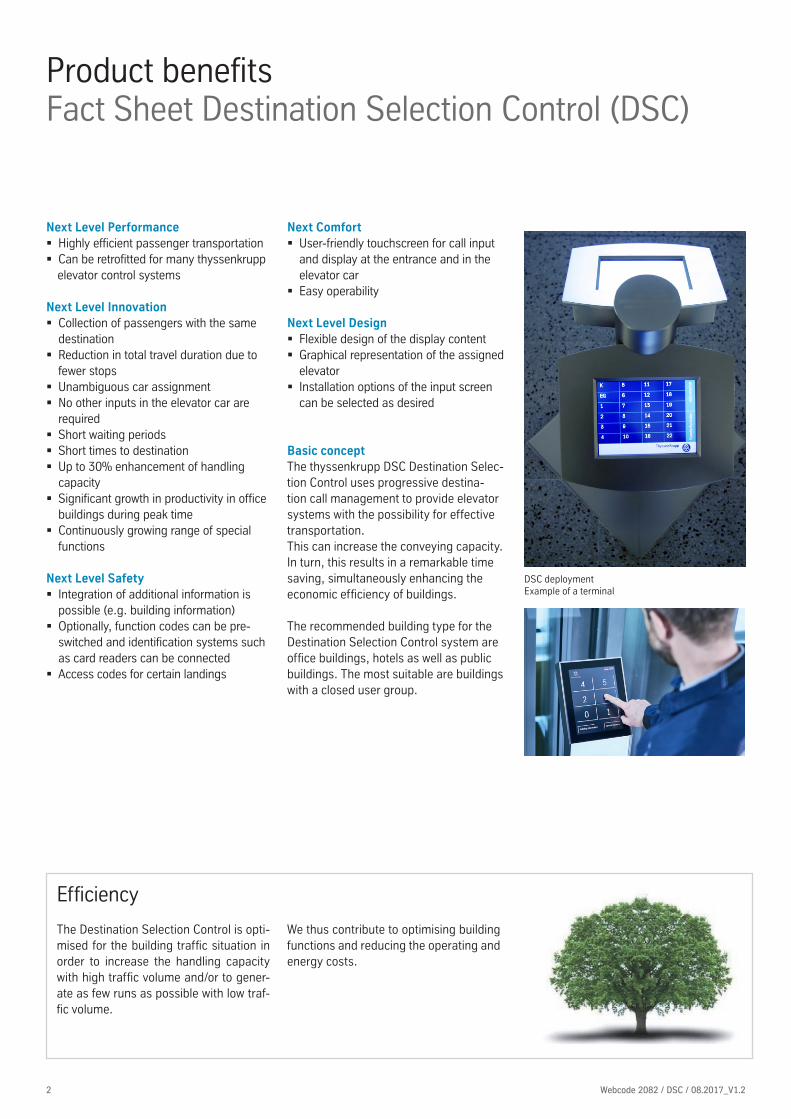
Conventional control system: � The user does not know how long they still have to wait
� It is unclear which elevator is to be used � There are many intermediate stops
Destination Selection Control (DSC): � The user is immediately assigned an elevator
� The time to destination is shortened � The number of intermediate stops is reduced
Description
Input of the destination landingIn an overall comparison with a conven-tional elevator control system, selecting the destination at the Destination Selection Control (DSC) involves not only entering the desired direction of travel but also of the exact destination landing of the passenger.
Assignment of the elevator carThe passenger enters their destination landing even before entering the elevator car on a control terminal. On the base of this information, the DSC can select the elevator in the group that is most suitable for each run in order to convey each pas-senger to their destination as quickly as possible. This avoids unnecessary jostling and uncertainties regarding the choice of elevator.
Basic conceptFact Sheet Destination Selection Control (DSC)
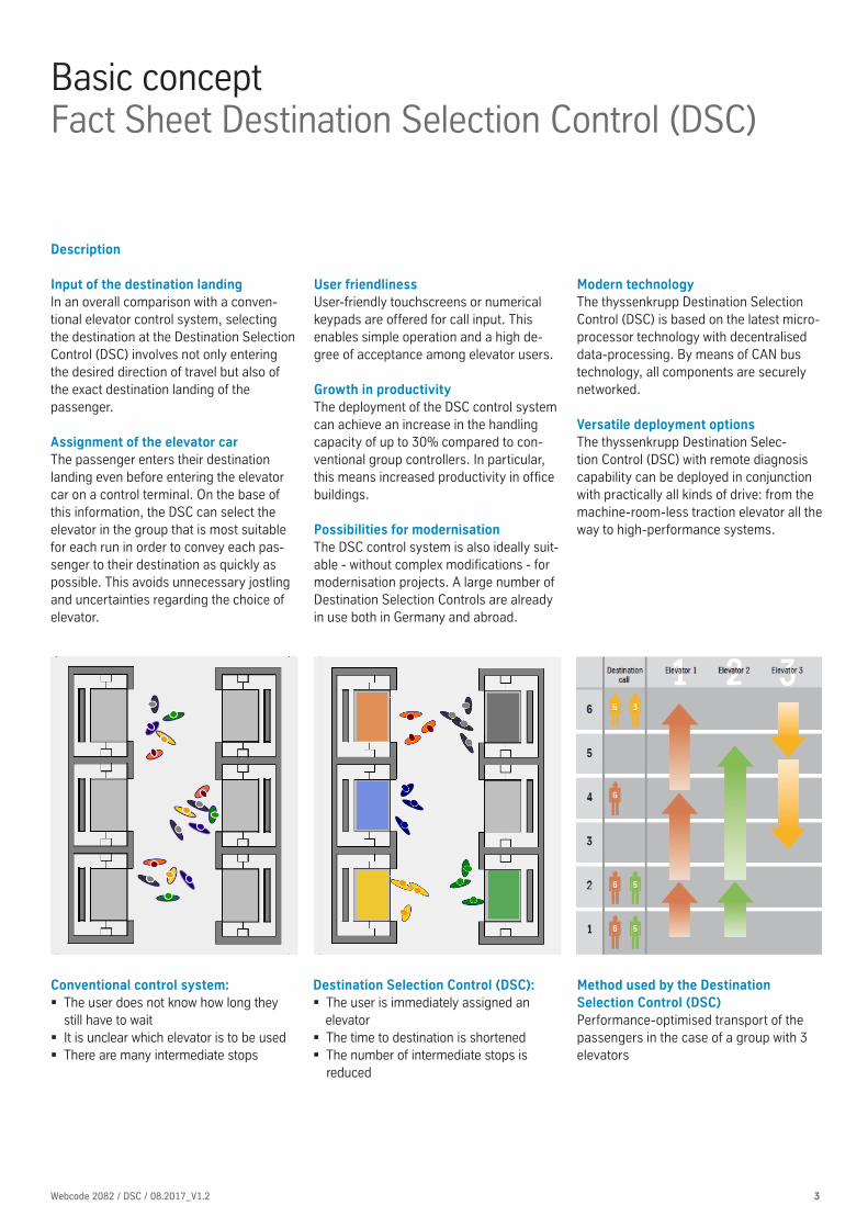
Method used by the Destination Selection Control (DSC)Performance-optimised transport of the passengers in the case of a group with 3 elevators
User friendlinessUser-friendly touchscreens or numerical keypads are offered for call input. This enables simple operation and a high de-gree of acceptance among elevator users.
Growth in productivityThe deployment of the DSC control system can achieve an increase in the handling capacity of up to 30% compared to con-ventional group controllers. In particular, this means increased productivity in office buildings.
Possibilities for modernisationThe DSC control system is also ideally suit-able - without complex modifications - for modernisation projects. A large number of Destination Selection Controls are already in use both in Germany and abroad.
Modern technologyThe thyssenkrupp Destination Selection Control (DSC) is based on the latest micro-processor technology with decentralised data-processing. By means of CAN bus technology, all components are securely networked.
Versatile deployment optionsThe thyssenkrupp Destination Selec-tion Control (DSC) with remote diagnosis capability can be deployed in conjunction with practically all kinds of drive: from the machine-room-less traction elevator all the way to high-performance systems.

4 Webcode 2082 / DSC / 08.2017_V1.2
Higher performance for groups of elevatorsFact Sheet Destination Selection Control (DSC)
Step 1: selection of the destination landingThe passenger enters their destination at a terminal in the landing, in response to which the most favourable elevator is calculated and assigned.
Step 2: elevator assignmentThe assigned elevator is immediately dis-played to the passenger. The display helps the user to find 'their' elevator quickly. The user goes to the assigned elevator. Depending on the setting, the image only remains on the screen for a short time or for a few seconds. The call entry screen then appears again.
Step 3: waitingThe passenger waits in front of the elevator assigned to them.
Step 4: run to destination landingNo more signals for movement are entered in the elevator car. Now only the assigned destination landings and the direction of travel to the next level position indicator (recommended) are displayed. The eleva-tor has fewer intermediate stops, enabling the passenger to reach their destination more quickly.
Positioning of the DSC terminal
Terminal at the entrance
A B
A B
Do not use the elevator in the case of fire!
Please select your destination floor
Special function Information
back
Please take lift C

OperationThe advantages of the Destination Selection Control (DSC) are particularly noticeable during the peak office hours in buildings. It reduces the waiting time and time to destination of the passengers to the highest degree. Where a Destination Selec-tion Control (DSC) is deployed, more runs at high speed can be completed, as the number of intermediate stops is reduced.
In summary, the Destination Selection Control (DSC) uses an intelligent call man-agement system to increase the handling capacity of groups of elevators.
5Webcode 2082 / DSC / 08.2017_V1.2 5
Optimised conveying performanceFact Sheet Destination Selection Control (DSC)
Planning recommendationTo optimise the selection of options, we would like to provide you with planning recommendations for some sample applications.
Regular users that do not change(office building etc.) � Next level display in each elevator car � Numerical keypad or touchscreen � Direction arrows at each entrance
Semi-public area - (school, university etc.) � Next level display in each elevator car � Touchscreen - simpler operation � Position indicator above / beside the main entrance (direction arrows, location, next destination landing)
� Direction arrows at each entrance
Public area - continuously changing users (hotel etc.) � Next level display in each elevator car � Touchscreen - simpler operation � Position indicator above / beside the main entrance (direction arrows, location, next destination landing)
� Direction arrows at each entrance
Public area - special case: hospital � Next level display in each elevator car � Touchscreen (e.g. 5.7") with numerical keypad
� Position indicator above / beside the main entrance (direction arrows, location, next destination landing)
� Direction arrows at each entrance
Recommended / possible display size
5.7" 10.4" 15"
Num
ber
of
land
ings
0 – 20
20 – 40 –
>40 –
recommended possible – not recommended / not possible
Comparison between conventional TCM control system and the Destination Selection Control (DSC)
Periode 6
Wartezeit (s)
Periode / Ankunftsrate der Passagiere pro 5 min
0
10
20
30
40
50
60
70
Periode 1 Periode 2 Periode 3 Periode 4 Periode 5 Periode 7
DSC TCM
10 % 11 % 12 % 13 % 14 % 15 % 16 % 17 %
80
90
100
TCM
DSC
Periode 6
Wartezeit (s)
Periode / Ankunftsrate der Passagiere pro 5 min
0
10
20
30
40
50
60
70
Periode 1 Periode 2 Periode 3 Periode 4 Periode 5 Periode 7
DSC TCM
10 % 11 % 12 % 13 % 14 % 15 % 16 % 17 %
80
90
100
TCM
DSC
waiting time (s)
Periode / Arrival rates of passengers per 5 min

6 Webcode 2082 / DSC / 08.2017_V1.2
Functional descriptionWhen a user approaches the numerical keypad, he or she is greeted with the text "Enter the floor". The destination to which the user would like to travel is entered by pressing a but-ton, or two buttons in quick succession for a two-digit landing number. Visual ac-knowledgement (only during operation) is provided by a surrounding red LED lighting ring and acoustically with a beep tone.
The entered landing is shown in the display positioned above the buttons.The texts are available in the languages German, English, French, Spanish and Russian. Other languages are available on request.
The landing entered is shown in the display directly after entry of the destination landing. After indication of the destination landing, the display indication changes and shows the elevator to be used.
The entered destination floor is then ap-proached without an further operation of operating elements in the elevator car.
Intermediate stops are possible if further users have been assigned to the same elevator. A position indicator in the elevator car landing shows the landing to which the elevator is currently moving.
EN 81-70 conformityTo comply with the EN 81-70 standard, the verbal announcements at the terminal and in the elevator car as well as buttons must be selected with haptic lettering.
Numerical keypad - descriptionFact Sheet Destination Selection Control (DSC)
� Rugged design � Optional EN 81-70 conformity � Low-cost variant � Simple operation � Can be individually adapted
The numerical keypad is a control device used for operating the elevator system by means of buttons arranged on a panel. The request for operation and the instruction to use the elevators are made on an integral LCD display. The arrangement and design of the control elements comply with the EN 81-70 standard (suitable for the disabled).
DesignThe LC display has a blue background on which the texts are shown in grey lettering. The backlit area of the display is 50 x 30 mm and the font size is 6 or 12 mm. The display is on four or two lines, depending on the font size.
ButtonsThe operating element (e.g. type MT42) are square short-stroke buttons with rounded corners and a matt pearl button plate (28 x 28 mm). The designation (0, 1, ..., 9) and symbols (*, wheelchair) are stamped directly into the button plate, making them haptic (suitable for the disabled) and very rugged. For the numerical keypad, other buttons with a separate cover plate can also be used.
With the innovative solution of the numeri-cal keypad, the traditional design has been continued and simultaneously combined with new technology. One advantage in particular is the design suitable for the disabled. The numerical keypad is a low-cost variant that convinces with its design and simple operation.
R66
240
R15
6
0
40
52
313,93
0 22,5
0
172,
50
195
106,
50
88,5
0
88
118
97,5
095
,75
187,
25A
A
B B
193
110
90
44
277
0
52,30
29,30
711,3022,90
75°
0
13,5
0
114,
55
09,50
31,2
9
A-A
0
11,75
71,25
0 11,7
5
71,2
5
B-B
Benennung:
Artikelnummer:
Datum
Name
ÄnderungZust.
Allgemeintoleranz
Datum
Name
Erst.
Gepr.
Ursp.
Rev.:
MATERIAL:
Bezeichnung:
Rothenh. Smartbutton Aufputzgehäuse
E760805
- -
-Oberfläche:
-
00
27.11.07
- - -- - -- - -- - --
---
Christ-Elektronik GmbHAlpenstraße 3487700 MemmingenTelefon (08331) 83 71-0Fax (08331) 83 71-99
A2
ISO 2768-fH
Maßstab: 1:1
7Webcode 2082 / DSC / 08.2017_V1.2 7
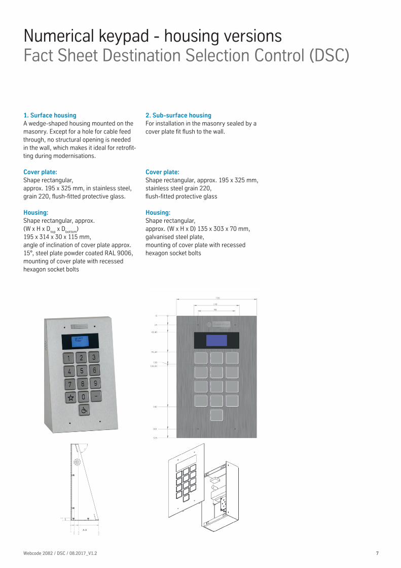
Numerical keypad - housing versionsFact Sheet Destination Selection Control (DSC)
2. Sub-surface housingFor installation in the masonry sealed by a cover plate fi t fl ush to the wall.
Cover plate: Shape rectangular, approx. 195 x 325 mm,stainless steel grain 220, fl ush-fi tted protective glass
Housing:Shape rectangular,approx. (W x H x D) 135 x 303 x 70 mm,galvanised steel plate,mounting of cover plate with recessedhexagon socket bolts
1. Surface housingA wedge-shaped housing mounted on the masonry. Except for a hole for cable feed through, no structural opening is needed in the wall, which makes it ideal for retrofi t-ting during modernisations.
Cover plate:Shape rectangular,approx. 195 x 325 mm, in stainless steel, grain 220, fl ush-fi tted protective glass.
Housing:Shape rectangular, approx. (W x H x D
top x D
bottom)
195 x 314 x 30 x 115 mm, angle of inclination of cover plate approx. 15°, steel plate powder coated RAL 9006, mounting of cover plate with recessed hexagon socket bolts
8 Webcode 2082 / DSC / 08.2017_V1.2
Numerical keypad - additional functionsFact Sheet Destination Selection Control (DSC)
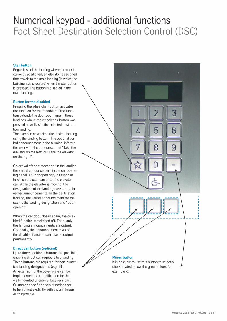
Star buttonRegardless of the landing where the user is currently positioned, an elevator is assigned that travels to the main landing (in which the building exit is located) when the star button is pressed. The button is disabled in the main landing.
Button for the disabledPressing the wheelchair button activates the function for the "disabled". The func-tion extends the door-open time in those landings where the wheelchair button was pressed as well as in the selected destina-tion landing.The user can now select the desired landing using the landing button. The optional ver-bal announcement in the terminal informs the user with the announcement "Take the elevator on the left" or "Take the elevator on the right".
On arrival of the elevator car in the landing, the verbal announcement in the car operat-ing panel is "Door opening", in response to which the user can enter the elevator car. While the elevator is moving, the designations of the landings are output in verbal announcements. In the destination landing, the verbal announcement for the user is the landing designation and "Door opening".
When the car door closes again, the disa-bled function is switched off. Then, only the landing announcements are output. Optionally, the announcement texts of the disabled function can also be output permanently.
Direct call button (optional) Up to three additional buttons are possible, enabling direct call requests to a landing. These buttons are required for non-numer-ical landing designations (e.g. B1).An extension of the cover plate can be implemented as a modifi cation for the wall-mounted or sub-surface versions. Customer-specifi c special functions are to be agreed explicitly with thyssenkrupp Aufzugswerke.
Minus button It is possible to use this button to select a story located below the ground fl oor, for example -1.

9Webcode 2082 / DSC / 08.2017_V1.2 9
TFT display - descriptionFact Sheet Destination Selection Control (DSC)
� Simple use � Can be individually adapted � High-quality manufacture
The convenient use of the touchscreens as well as the clear and dynamic design com-ply with a standard and can be customised to customer preferences. The standard housing with the TFT display is offered in two variants: as a surface housing and as a column.
The column is approx. 1200 mm high, making it optimal for every user. Optionally many customer requirements can be real-ized: eg logo as screen printing, disabled button, additional cut-out and mounting for loudspeakers, etc.
The versions are available in stainless steel, grain 220, but can be painted individually in any RAL shade. The display version can also be individually adapted to the customers need. The design surfaces as well as the display sizes are available in the versions 5.7 inches, 10.4 inches and 15.0 inches. Clearly arranged graphical interfaces en-sure intuitive operation of the touchpanels. The design, user interface and construc-tion of the terminal can be adapted indi-vidually to the peculiarities of the building and style specifi cations.
Numerous special applications such as identifi cation systems or networking with entry control systems expand the DSC range of performance.
Column, version 10.4 inches
Column, version with 15.0 Zoll
Surface housing, version 10.4 inchesDSC terminal with TFT display (10.4 inch), in versions for surface mounting, for submerged installation or in a column
10 Webcode 2082 / DSC / 08.2017_V1.2
TFT display - versionsFact Sheet Destination Selection Control (DSC)
Touch-it Ceviro 10.4 TFT (OEM Thyssen)
Datasheet
http://www.christ-elektronik.de Page 3 / 5
Pinout
Front View (mm)
Touch-it Cevipro 5.7 TFT (OEM Thyssen)
Datasheet
http://www.christ-elektronik.de Page 4 / 5
Touch-it Ceviro 10.4 TFT (OEM Thyssen)
Datasheet
http://www.christ-elektronik.de Page 4 / 5
Touch-it Cevipro 5.7 TFT (OEM Thyssen)
Datasheet
http://www.christ-elektronik.de Page 3 / 5
Pinout
Front View (mm)
Touch-it Cevipro 15 TFT (OEM Thyssen)
Datasheet
http://www.christ-elektronik.de Page 4 / 5
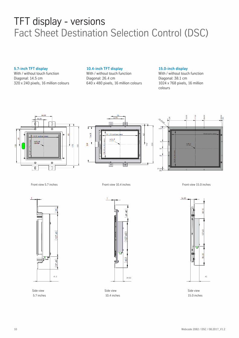
5.7-inch TFT displayWith / without touch functionDiagonal: 14.5 cm320 x 240 pixels, 16 million colours
10.4-inch TFT displayWith / without touch functionDiagonal: 26.4 cm640 x 480 pixels, 16 million colours
15.0-inch displayWith / without touch functionDiagonal: 38.1 cm1024 x 768 pixels, 16 million colours
Front view 5.7 inches
Side view
5.7 inches
Front view 10.4 inches
Side view
10.4 inches
Touch-it Cevipro 15 TFT (OEM Thyssen)
Datasheet
http://www.christ-elektronik.de Page 3 / 5
Pinout
Front View (mm)
Side view
15.0 inches
Front view 15.0 inches
150 22
4
4241.5

11Webcode 2082 / DSC / 08.2017_V1.2 11
1. Surface housingThe housing is made of stainless steel, grain 220, but can be individually painted in any RAL shade. It is wedge-shaped and can be place on the masonry, making it ideally suitable for retrofitting in the case of modernisations.
5.7" housing:Shape rectangular, approx. (W x H x D top x D bottom)approx. 200 x 180 x 39 x 78.5 mm,angle of inclination, cover plate approx. 14°
10.4" housing:Shape rectangular, approx. (W x H x D
top x D
bottom)
approx. 310 x 248 x 35 x 89 mm,angle of inclination, cover plate approx. 14°
15" housing:Shape rectangular, approx. (W x H x D top x D bottom)approx. 380 x 330 x 25 x 97 mm,angle of inclination, cover plate approx. 14°
5.7" front view
5.7" side view
10.4" front view
10.4" side view
15" front view
TFT display - operating elements at the entranceFact Sheet Destination Selection Control (DSC)
front view of the column side view of the column
2. ColumnThe columns are very elegant in design, with bevelled user interface.The assembly is ideally done on the raw floor, also in order to be able to conceal the supply lines concealed.
Housing:The shape is rectangular and the angle of inclination of cover plate is 60° and 35°, respectively, relactive to the vertical.
This column has already been implemented for numerous projects and is designed with tested dimensions. Depending on customer requirements, the dimensions can be adapted in the individual project.
���������������
�
�
�
�
363
953
35°
8V
erst
ellb
arvo
n 25
mm
bis
125m
m
480408�
251
3
65,5
251
1252
Aushängbar
68,5
���������������
�
�
�
�
363
953
35°
8V
erst
ellb
arvo
n 25
mm
bis
125m
m
480408�
251
3
65,5
251
1252
Aushängbar
68,5
5.7" front view
10,4" front view
10,4" side view
10,4" front view
10,4" side view

12 Webcode 2082 / DSC / 08.2017_V1.2
1. Standard indicator elements above the door
LCD Blue Line, shape: oval or angular,approx. (W
outer x W
inner x H x D )
approx. 280 x 243 x 110 x 72 mm,LCD position indicator and direction indicator. Installation in the entrance area above the landing door (including gong). Version: LCD, blue-white, blue background, white lettering. Installation in the entrance: flush-fitted protective glass. Cover plate made of stainless steel grain 220 (in ac-cordance with EN 81-70).
Favorit: shape: oval or angular,approx. (W
outer x W
inner x H x D )
approx. 280 x 243 x 110 x 72 mm,LED position and direction indicator (red LED dot matrix display). Additionally a gong can be installed in the indicator box. Cover plate made of stainless steel grain 220.
TFT display - indicator elements at the entranceFact Sheet Destination Selection Control (DSC)
For the indicator elements at the en-trance, you have a choice between our standard indicators and the TFT indica-tor elements.
10.4" front view
10.4" side view
15" front view
15" side view
5.7 " display
2. TFT - indicator elements above the door
The housing is made of stainless steel, grain 220, but can be individually paint-ed in any RAL shade. It is wedge-shaped and can be place on the masonry, mak-ing it ideally suitable for retrofitting in the case of modernisations.
5.7" housing:Shape rectangular, approx. (W x H x D
top x D
bottom)
approx. 200 x 180 x 39 x 78.5 mm,angle of inclination, cover plate approx. 14°
10.4" housing:Shape rectangular, approx. (W x H x D
top x D
bottom)
approx. 310 x 248 x 35 x 89 mm,angle of inclination, cover plate approx. 14°
15" housing:Shape rectangular, approx. (W x H x D
top x D
bottom)
approx. 380 x 330 x 25 x 97 mm,angle of inclination, cover plate approx. 14°
5.7" front view
5.7" side view

13Webcode 2082 / DSC / 08.2017_V1.2 13
TFT display - indicator elements in the elevator carFact Sheet Destination Selection Control (DSC)
You have the possibility to use TFT displays in the elevator car. However, the width and depth must be borne in mind for both the cover plate and the basic body of the car operating panel.Standard indicators are of course possi-ble, but we recommend deployment of a TFT display with the 'Next Level' display so that the passenger is informed of the next destinations to be approached.
TFT display, 5.7 inches
Size of display:W x H x D176 x 188 x 41.5 mm and/or176 x 150 x 41.5 mm without tabs / clips
Width of car operating panel with horizon-tal installation position: � at least 205 mm � Connections at top
Width of car operating panel with vertical installation position: � at least 205 mm � Connections on the right
TFT display, 10.4 inches
Size of displayW x H x D274 x 262 x 39.5 mm and/or274 x 224 x 39.5 mm without tabs / clips
Width of car operating panel with horizon-tal installation position: � at least 320 mm � Connections at top
Width of car operating panel with vertical installation position:• at least 280 mm • Connections on the right
Next Level indicator
TFT display, 15 inches
Size of displayW x H x D355 x 282 x 42.0 mmno tabs / clips present
Width of car operating panel with horizontal installation position: � at least 380 mm � Connections at top
Width of car operating panel with verti-cal installation position:• at least 300 mm • Connections on the right
Display texts on the TFT display
Standard texts Display text
Special travel SPECIAL TRAVEL
Collective fault signal ELEVATOR MALFUNCTION
Emergency power EMERGENCY POWER MODE
Out of service OUT OF SERVICE
Overload OVERLOAD
Priority PRIORITY
Fire service FIRE EMERGENCY CONTROL
Occupied OCCUPIED
14 Webcode 2082 / DSC / 08.2017_V1.2
TFT display - additional functionsFact Sheet Destination Selection Control (DSC)
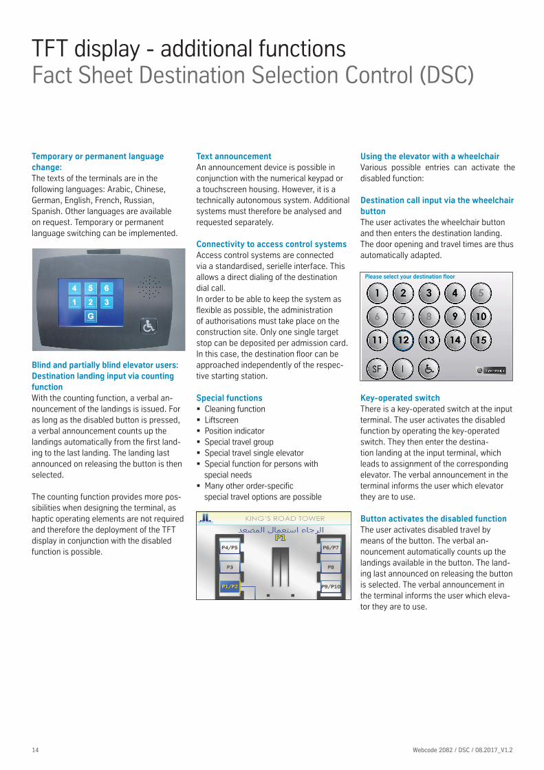
Blind and partially blind elevator users: Destination landing input via counting functionWith the counting function, a verbal an-nouncement of the landings is issued. For as long as the disabled button is pressed, a verbal announcement counts up the landings automatically from the first land-ing to the last landing. The landing last announced on releasing the button is then selected.
The counting function provides more pos-sibilities when designing the terminal, as haptic operating elements are not required and therefore the deployment of the TFT display in conjunction with the disabled function is possible.
Using the elevator with a wheelchairVarious possible entries can activate the disabled function:
Destination call input via the wheelchair buttonThe user activates the wheelchair button and then enters the destination landing. The door opening and travel times are thus automatically adapted.
Key-operated switchThere is a key-operated switch at the input terminal. The user activates the disabled function by operating the key-operated switch. They then enter the destina-tion landing at the input terminal, which leads to assignment of the corresponding elevator. The verbal announcement in the terminal informs the user which elevator they are to use.
Button activates the disabled functionThe user activates disabled travel by means of the button. The verbal an-nouncement automatically counts up the landings available in the button. The land-ing last announced on releasing the button is selected. The verbal announcement in the terminal informs the user which eleva-tor they are to use.
Text announcementAn announcement device is possible in conjunction with the numerical keypad or a touchscreen housing. However, it is a technically autonomous system. Additional systems must therefore be analysed and requested separately.
Temporary or permanent language change:The texts of the terminals are in the following languages: Arabic, Chinese, German, English, French, Russian, Spanish. Other languages are available on request. Temporary or permanent language switching can be implemented.
Connectivity to access control systemsAccess control systems are connected via a standardised, serielle interface. This allows a direct dialing of the destination dial call.In order to be able to keep the system as flexible as possible, the administration of authorisations must take place on the construction site. Only one single target stop can be deposited per admission card. In this case, the destination floor can be approached independently of the respec-tive starting station.
Please select your destination floor
Special functions � Cleaning function � Liftscreen � Position indicator � Special travel group � Special travel single elevator � Special function for persons with special needs
� Many other order-specific special travel options are possible

15Webcode 2082 / DSC / 08.2017_V1.2 15
DescriptionVarious interface designs can be selected. These can be individually adapted to the building.
TFT display - examples of interface designsFact Sheet Destination Selection Control (DSC)
1. Normal operationThe user selects the desired destination landing, in response to which the optimal elevator is calculated and assigned.
2. Assignment screenThe assigned elevator is displayed.
3. Position indicator in the elevator car (optional)The next destinations to be approached by the elevator are shown on the position indicator.
Design Classical:
Design Elegant:
Design Modern:
Please take lift 3
Infor-mation
Special function
Do not use the elevator in the case of fire!
Please select your destination floor
Special function Information back
Please take lift C
Please select your destination floorPlease take lift 3

16 Webcode 2082 / DSC / 08.2017_V1.2
TFT display - examples of interface designs Fact Sheet Destination Selection Control (DSC)
Individual interface designs
thyssenkrupp implements your individual customer wishes!

17Webcode 2082 / DSC / 08.2017_V1.2 17
DSC booster Fact Sheet Destination Selection Control (DSC)
� Connection of DSC functions and con-ventional control system
� Optimisation of the up peak � Architectural freedom � Simple operation
TCM with DSC booster is the combination of conventional control systems with the functions of a Destination Selection Control (DSC) (in the main landing). A complete overview of the entire traffi c situation enables each individual control system to optimise handling of the incom-ing calls and commands.This progressive call management system results in the most effective transport control for a conventional TCM group controller.The improved performance results in a signifi cant time gain for the passenger. In-novative technology in the call input system signifi cantly enhances the entrance area of the elevator systems. The possibility for installation in any hous-ing provides the maximum architectural freedom – functionally simple, sophisticat-edly elegant or adapted to the fi ttings and furnishings of the foyer.Simple operation with graphical user guidance leads to rapid assignment of an elevator and thus the greatest possible acceptance among users.
OperationIn the main landing, the desireddestination landing is entered at the desti-nation selection terminal and the elevator to be used is assigned immediately. On the other fl oors, operation is conventional. The elevator is called (direction-sensitive) using the call button at the entrance and the destination landing is entered at the car operation panel in the elevator car.
StructureThe DSC booster is integrated in the TCM group controller. A number of destination selection terminals are placed in the main landing and in other important landings. There are conventional operating ele-ments on the remaining fl oors. The usual operating panel is installed in the eleva-tor cars, but this has no function in the booster landing.The direct assignment of the correspond-ing elevator by the of the DSC booster after call input in the main landing ex-ploits the advantages of the Destination Selection Control (grouping) in the main landing. This in turn means that a much greater number of persons compared to a conventional group of elevators is distrib-uted from the main landing in the building.
OptionBlocking car call input until the fi rst land-ing requested by an external call is reached.
Time
Num
ber
of c
onve
yed
pers
ons
in th
e m
ain
land
ing
Conventional group controller
DSC booster group contro
ller
Lobby
1
2
3
4

COMPONENTS NUMERICAL
KEYPAD
TOUCH IN 1 OR
MORE LANDINGS
TOUCH IN ALL
LANDINGS
Control elements
In the elevator car
Mechanical button for each landing ¡ l ¡
Touchscreen (Car Operation Panel) 5.7", 10.4", 15" ¡ ¡ ¡
at entrance
5.7", 10.4", 15" touchscreen ¡ l l
Numerical keypad l – ¡
Display elements
In the elevator car (Next Level)
5.7", 10.4", 15" with car call acknowledgement indicator ¡ ¡ ¡
At the entrance (standard indicators)
Blue Line, red dot matrix ¡ ¡ ¡
At the entrance (TFT displays)
5.7", 10.4", 15" with car call acknowledgement indicator ¡ ¡ ¡
Housing
Wall-mounted l l l
Sub-surface ¡ – –
Column – ¡ ¡
Interface designs
Standard l l l
Customer-specific – ¡ ¡
Standard functions
Simple special travel * ¡ l l
Cleaning function** ¡ l l
Automatic calling via code card *** ¡ ¡ ¡
One entrance side or offset / dual entrance on same landing ¡ l l
Additional functions
Selective front and rear entrances – l l
Dynamic Group Controller (DGC) l – l
Zoning: division of the building into zones (only available for TWIN®) ¡ – ¡
Entry control
For a user group by means of a voltage free contact at the terminal ¡ ¡ ¡
For a number of user groups (≤ 16 landings), by means of voltage free contacts at the terminal, shaft or machine room
¡ ¡ ¡
For a number of user groups (> 16 landings), by means of serial interface in the elevator control system
¡ ¡ ¡
Energy saving function
Reduction of the active shafts in low-traffic periods ¡ – ¡
Dimming / darkening after an adjustable time – ¡ ¡
Suitable for the disabled
Based on DIN 81-70
(wheelchair button on touchscreen)– l l
Compliance with DIN 81-70(haptic buttons, verbal announcement inside / outside)
¡ ¡ ¡
Standard l Option ¡ unavailable –
18 Webcode 2082 / DSC / 08.2017_V1.2
Overview of the optionsFact Sheet Destination Selection Control (DSC)
* Special travel:
1. On the default screen, the SF button
is pressed
2. Code for special function is entered
on the numerical keypad
3. Open special travel screen
4. Call request
5. Call is assigned to a shaft or 'landing
blocked' appears.
NB: in the case of TWINs®, it can be
that an elevator car is blocked by the
special travel of another elevator car.
6. Existing destination selection calls
are carried out, then the elevator
car is made available for the special
travel
7. Special travel is executed
** Cleaning function:
1. On the default screen, the SF button
is pressed
2. Code for special function is entered
on the numerical keypad
3. Open cleaning function screen
4. Selection of the elevator car
5. Elevator car comes to the landing in
which the code was entered, is taken
out of the group and opens the door
6. Open / close button remains active
(inner door cleaning)
7. After cleaning, the function must be
switched off again at the terminal
*** Code card:
1. A serial interface is required
2. A single destination floor can be
deposited for each entitlement card
3. The destination floor can be
approached independently of the
starting station

Other references
� Qipco Office Tower (Tornado Tower), Qatar
� Raine Square, Perth, Australia � Rabobank, Utrecht, The Netherlands � Palais Quartier (MyZeil), Frankfurt, Germany
� European Central Bank, Frankfurt, Germany
� Federation Tower, Moscow, Russia � Mercury Tower, Moscow, Russia � Maintriangel, Frankfurt, Germany � Dalian Bayshore Hotel, China � Altra Sede, Milan, Italy � Ropemaker Place, London, United Kingdom
� New Stock Exchange, Frankfurt, Germany
� Skyline Tower, Munich, Germany � London Wall 125, London, United Kingdom
� CMA Tower Riad, Saudi Arabia � Dong Won, Korea � Castellana, Spain � Beijing Olympic Tower, China � Lot 2, 3, 11, Russia � Litex Tower Sofia, Bulgaria
19Webcode 2082 / DSC / 08.2017_V1.2 19
International referencesFact Sheet Destination Selection Control (DSC)
St. Botolphs House London, United Kingdom
London Wall 125 London, United Kingdom
Litex Tower Sofia, Bulgaria
thyssenkrupp Headquarters, Essen, Germany
BMW High-rise, Munich, Germany
University of Stuttgart, Germany

20
ELEVATOR
ThyssenKrupp Aufzugswerke GmbHBernhäuser Straße 45 • 73765 Neuhausen a.d.F. • GermanyTelephone +49 (0) 7158 12-0 • Telefax +49 (0) 7158 12-2585www.thyssenkrupp-elevator-eli.com • [email protected]
The individual details given in this publication are deemed to be warranted characteristics,insofar as such are confi rmed in writing in each individual case.
Presented by
Webcode 2082 / DSC / 08.2017_V1.2