Embed Size (px)
Citation preview
CONSULTANCY SERVICES FOR
PREPARATION OF PROJECT REPORT FOR NANDED
UNDERGROUND SEWERAGE SCHEME FOR NANDED WAGHALA
CITY MUNICIPAL CORPORATION, NANDED (Zone-III)
DETAIL PROJECT REPORT VOLUME - I
June, 2006
SUNGRACE ENGINEERING ROJECTS Pvt. Ltd. Engineers & Consultants. Survey No. 19, H.No. (6+7) / 5, Bavdhan Khurd, Pune-411021 Phone : 2951225 / 2951226 Fax. No. 2951205
Maharashtra Jeevan Pradhikaran Circle, Nanded.
Maharashtra Jeevan Pradhikara, Works Division, Nanded.

MAHARASHTRA JEEVAN PRADHIKARAN CIRCLE, NANDED
MAHARASHTRA JEEVAN PRADHIKARAN WORKS
DIVISION, NANDED
NANDED UNDERGROUND SEWERAGE SCHEME FOR NWCMC NANDED
CERTIFICATE
Certified that 10 % supervisory check has been exercised in this office and
calculations are to be found correct.
Assistant Engineer Gr. II
Assistant Superintending Engineer,
Maharashtra Jeevan Pradhikaran Circle, Nanded
Superintending Engineer, Maharashtra Jeevan Pradhikaran Circle,
Nanded
MAHARASHTRA JEEVAN PRADHIKARAN CIRCLE, NANDED
MAHARASHTRA JEEVAN PRADHIKARAN WORKS
DIVISION, NANDED
NANDED UNDERGROUND SEWERAGE SCHEME FOR NWCMC NANDED
CERTIFICATE
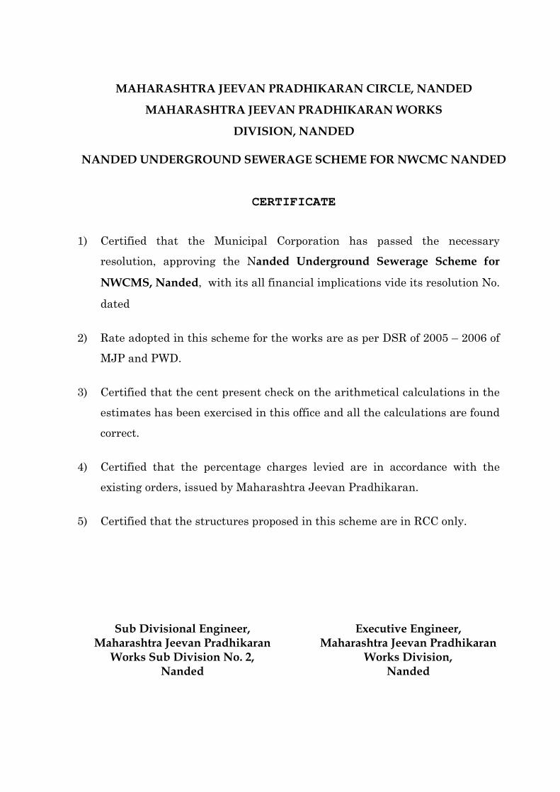
1) Certified that the Municipal Corporation has passed the necessary
resolution, approving the Nanded Underground Sewerage Scheme for
NWCMS, Nanded, with its all financial implications vide its resolution No.
dated
2) Rate adopted in this scheme for the works are as per DSR of 2005 – 2006 of
MJP and PWD.
3) Certified that the cent present check on the arithmetical calculations in the
estimates has been exercised in this office and all the calculations are found
correct.
4) Certified that the percentage charges levied are in accordance with the
existing orders, issued by Maharashtra Jeevan Pradhikaran.
5) Certified that the structures proposed in this scheme are in RCC only.
Sub Divisional Engineer,
Maharashtra Jeevan Pradhikaran Works Sub Division No. 2,
Nanded
Executive Engineer, Maharashtra Jeevan Pradhikaran
Works Division, Nanded

MAHARASHTRA JEEVAN PRADHIKARAN CIRCLE, NANDED
MAHARASHTRA JEEVAN PRADHIKARAN
WORKS DIVISION, NANDED
NANDED UNDERGROUND SEWERAGE SCHEME FOR NWCMC NANDED
CHECK LIST
Name of Town : Nanded-Waghala
District : Nanded
Class of Municipal
Corporation
: ‘C’ Class
Population –
1991 Census : 280077
2001 Census : 3,75,828
2038 Census : 11,54,273
(Populations are of Administrative Zone 1,2,3
& 4 of NWCMC)
Backlog or Non Backlog –
Sr. No.
Particulates Information
1 2 3
1) Name of Town District class of M.C. Population Backlog or Non backlog etc.
Nanded-Waghala City Municipal Corporation Population 2001– 3,75,828 2008 – 4,62,930 2023 – 7,28,393 2038 – 11,54,273 (Populations are of Administrative Zone 1,2,3 & 4 of NWCMC)
2) Details of the Present Sewerage Scheme.
There is a Old Sewerage Disposal Scheme in town which is collapsed since 1985, majority laterals of Sewerage network are functioning and draining in local Nallas and ultimately into river.
3) Ownership of the scheme and existing scheme run by.
Nanded-Waghala City Municipal Corporation
1 2 3
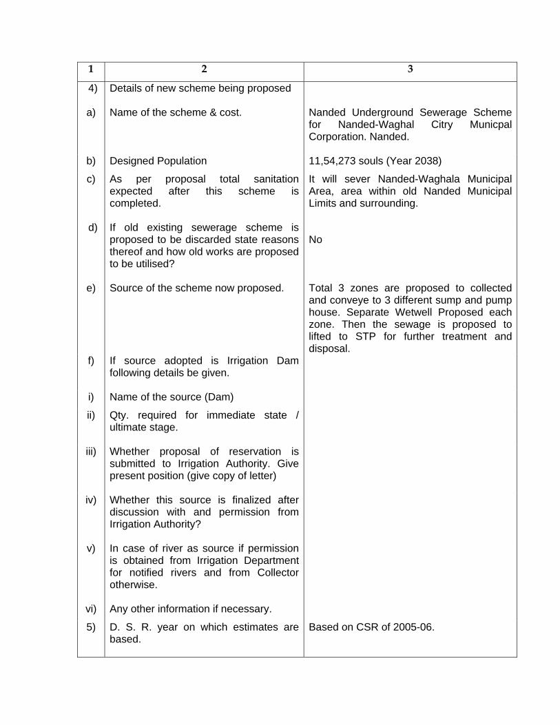
4) Details of new scheme being proposed
a) Name of the scheme & cost.
Nanded Underground Sewerage Scheme for Nanded-Waghal Citry Municpal Corporation. Nanded.
b) Designed Population 11,54,273 souls (Year 2038)
c) As per proposal total sanitation expected after this scheme is completed.
It will sever Nanded-Waghala Municipal Area, area within old Nanded Municipal Limits and surrounding.
d) If old existing sewerage scheme is proposed to be discarded state reasons thereof and how old works are proposed to be utilised?
No
e) Source of the scheme now proposed.
Total 3 zones are proposed to collected and conveye to 3 different sump and pump house. Separate Wetwell Proposed each zone. Then the sewage is proposed to lifted to STP for further treatment and disposal.
f) If source adopted is Irrigation Dam following details be given.
i) Name of the source (Dam)
ii) Qty. required for immediate state / ultimate stage.
iii) Whether proposal of reservation is submitted to Irrigation Authority. Give present position (give copy of letter)
iv) Whether this source is finalized after discussion with and permission from Irrigation Authority?
v) In case of river as source if permission is obtained from Irrigation Department for notified rivers and from Collector otherwise.
vi) Any other information if necessary.
5) D. S. R. year on which estimates are based.
Based on CSR of 2005-06.
1 2 3
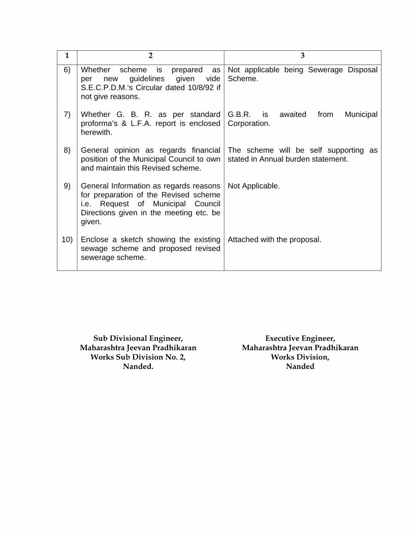
6) Whether scheme is prepared as per new guidelines given vide S.E.C.P.D.M.‘s Circular dated 10/8/92 if not give reasons.
Not applicable being Sewerage Disposal Scheme.
7) Whether G. B. R. as per standard proforma’s & L.F.A. report is enclosed herewith.
G.B.R. is awaited from Municipal Corporation.
8) General opinion as regards financial position of the Municipal Council to own and maintain this Revised scheme.
The scheme will be self supporting as stated in Annual burden statement.
9) General Information as regards reasons for preparation of the Revised scheme i.e. Request of Municipal Council Directions given in the meeting etc. be given.
Not Applicable.
10) Enclose a sketch showing the existing sewage scheme and proposed revised sewerage scheme.
Attached with the proposal.
Sub Divisional Engineer,
Maharashtra Jeevan Pradhikaran Works Sub Division No. 2,
Nanded.
Executive Engineer, Maharashtra Jeevan Pradhikaran
Works Division, Nanded

MAHARASHTRA JEEVAN PRADHIKARAN
WORKS DIVISION, NANDED.
NANDED UNDERGROUND SEWERAGE SCHEME FOR NWCMC NANDED
DETAILED PROJECT REPORT 1.1 PREAMBLE
Safe water supply and hygienic sanitation facilities are the two basic essential amenities,
the community needs on a top priority for healthy living. While provision of safe drinking
water takes precedence in the order of provision of basic amenities to community, the
importance of hygienic sanitation facilities through low cost on-site sanitation,
conventional sewerage and sewage treatment can no longer be allowed to lag behind,
as about 80 % of water used by the community comes out of houses in the form of
waste water which unless properly collected, conveyed, treated and safely disposed of
may eventually pollute our precious water resources and cause environmental
degradation.
Maharashtra Jeevan Pradhikaran Works Division proposes to prepare the
Detailed Project Report of Under Ground Sewerage Scheme for Municipal Corporation
area of Nanded-Waghala City Municipal Corporation area, excluding Southern Area of
Corporation i.e. CIDCO, Waghala Area beyond south of Godavari River, on the demand
of Nanded-Waghala City Municipal Corporation.
Nanded is a Politically and Historically a Major City in Maharashtra. Shrine of Shri
Guru Gobindsinghji is in Nanded City, so it’s a Holi Place of Sikhs. Thousands of
Pilgrimagers visit Sachkhhand Gurudwara of Nanded every Year. Nanded is developed
on Banks of Godavari River, Longitudes 77.7o to 78.15o East and Latitude 18.15o to
19.55o North and at an Average Altitude of 360 mtrs above mean sea level. Its about
550 kms from the State Capital Mumbai, having Municipal Corporation, Established on
26’th March 1997. The city is on Major Train Route Mumbai-Secundrabad and also on
Major State Highways 2,3 and 6 and likely to be upgraded to National Highways.
Nanded is Important center for Fruit, Grains, Cotton Market as well as other general
Agricultural Products. Nanded is also having traditional reputation of Handloom cloths;
there are many Hand Looms in Nanded as well as Powers also. Apart from, its
developed as a Educational Center having Shri Swami Ramanand Tirth University,
Medical College, Aurvedic College, Two Engineering Colleges, Polytechnic College and
other many and reputed Educational Institutes. Many Major Important Government
offices are also functioning in City.
Sachkhand Hujursahib Gurudwara, is having very high historical and religious
significance. It was in Nanded, that Shri Guru Gobind Singhji the last Guru of Sikh
Religion declared the consecration of the Guru Granth Sahib as the last Guru of Sikh
Religion and left his heavenly abode. The tri centenary of Gurta – Gaddi is going to
celebrate in the year 2008 in the month of October. For this 25-30 lakh pilgrims are
expected to participate. Local authority is focusing on improving the Infrastructural
Development of the city.
1.2 CONSULTANCY
Consultancy work for Survey preparation of plans and estimates for underground
Sewerage scheme has been entrusted to Sungrace Engineering Projects Pvt. Ltd. Pune.
Vide agreement No. B-1/3 of 2005–2006 dated 05/09/2005.
The Service includes the task of carrying out detailed engineering survey of Nanded City
Municipal Limits for transmission system, data collection existing arrangements, and
detailed design of the system. It also includes the Capacity design of S.T.P. proposals.
The present report deals and elaborates the detailed survey carried out and other data
collected for Structuring of the scheme as whole based on the investigations.
1.3 TOPOGRAPHY & SURVEY
Nanded is situated on Banks of Godavari River, Longitudes 77.7o to 78.15o East
and Latitude 18.15o to 19.55o North and at an Average Altitude of 360 mtrs above mean
sea level. The highest level in the city area is about 373 mtr above MSL. The Nanded
City is divided in 3 parts, separating boundaries by Railway Line and Godavari River.
Area north of Railway Line, Old city is in between Godavari River and Railway Line and
the Sub Urban area and newly attached Municipal Council area of then Waghala
Municipal Council. The general Slope of City is towards River from north and south
sides of city. The projected area is the North of River excluding the area on the south of
river. The projected area is sloping towards Godavari River. The corporation limit is the
dividing Ridge of Godavari and Asana River a tributary of it. Only the Natural Drain
originating from Hanuman Gargh flows towards Asana River after the railway crossing.
Otherwise all Major Natural Drains confluence the Godavari River.
1.3.1 SURVEY
Extensive (Chain and Campass) survey is carried out in the Nanded Municipal
Corporation Limits with network of T.B.Ms. fixed in the area leveling are carried out.
M.S.L. at River Gauging Station on Old Bridge is taken as reference G.T.S. benchmark.
The level is 342.500 m. L-Sections, leveling of Major Nalla is proposed to conduct as
per the necessary to conveyance system.
1.4 Design Data
1.4.1 Population Forecasting is calculated as per standard practice of MJP as per the
population given by MJP in TOR. The wardwise population forecasting is also calculated
considering the growth rate and the respective population densities of the wards. The
forecasting densities are based on the development limitations in the old city Wards. The
densities for developing wards are also proposed considering the total growth of
population in year 2038.
1.4.2 RAINFALL DETAILS
The nearest rain gauge is Sonegam. The rainfall details as follows –
Max. Rainfall 1300.3 mm
Min. Rainfall 923.8 mm
Avg. Rainfall 864.0 mm (Based on Last 50 years)
1.4.3 TEMPERATURE
The Average temperatures are as follows –
In Winter Avg. Maximum 25oC
In Summer Avg. Maximum Temperature 43oC
1.5 WATER SUPPLY ARRANGEMENTS
Nanded City is getting treated water from the W.S. operated by Corporation and CIDCO.
The total supply is considered @ 135 lpcd. City is having Godavari River as source with
four head works situated on the banks of Godavari 2 in submergence of Shankar Sagar
(Vishnupuri Dam ) and two downstream of Dam. Nanded City is having three WTP.
Oldest WTP is commissioned in 1985 of Cap. 27 MLD. Treated water is served to
CIDCO from WTP of Capacity 12.5 MLD. Major Part of the City is being served with the
WTP having Capacity 60 MLD. Presently average rate of water supply is 85 lpcd. The
works under various Stages of Nanded Distribution System and 6 Villages are in
progress. Which includes ESR’s, Pure Water Rising Main and Distribution system, which
will improve the rate of water supply in the city and proposed to be served at 135 lpcd.
1.6 EXISTING SANITATION SYSTEM & DISPOSAL
Sewerage project is the most expensive option in sanitation. It not only
requires high capital cost but also involves high operation and maintenance charges
besides requiring considerable experience and expertise. Though state of
Maharashtra is considered to be one of the advanced progressive states very few
towns and urban areas have sewerage facilities as these can not meet the full
financial cost of these facilities. Nanded city is having a sewerage scheme. Which was commissioned in 1967,
which was designed with the considerations of Ultimate Stage of year 1994 for
population 1,50,000. It covers only the part of Nanded City. The features and
components are as follows.
Immediate Stage (1973) - 1,00,000 souls
Ultimate Stage (1994) - 1,50,000 souls
Sewage flow - 110 lpcd
Drainage Districts - 6 Nos.
Number of Wards Covered - 9 Nos.
Intercepting Sewers - 5 Nos.
Components
Intercepting Sewer Network Particular of Sewer
Diameters / Type of Pipe
Area Covered (Presently) Present Condition
A Sewer 225 - 900 Originating from Ganesh Nagar, Labour Colony, Yeshwant Nagar,
Choked up at several Locations and discharge is diverted
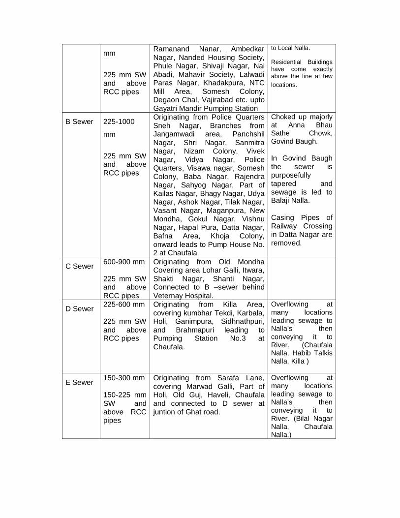
mm
225 mm SW and above RCC pipes
Ramanand Nanar, Ambedkar Nagar, Nanded Housing Society, Phule Nagar, Shivaji Nagar, Nai Abadi, Mahavir Society, Lalwadi Paras Nagar, Khadakpura, NTC Mill Area, Somesh Colony, Degaon Chal, Vajirabad etc. upto Gayatri Mandir Pumping Station
to Local Nalla. Residential Buildings have come exactly above the line at few locations.
B Sewer 225-1000
mm
225 mm SW and above RCC pipes
Originating from Police Quarters Sneh Nagar, Branches from Jangamwadi area, Panchshil Nagar, Shri Nagar, Sanmitra Nagar, Nizam Colony, Vivek Nagar, Vidya Nagar, Police Quarters, Visawa nagar, Somesh Colony, Baba Nagar, Rajendra Nagar, Sahyog Nagar, Part of Kailas Nagar, Bhagy Nagar, Udya Nagar, Ashok Nagar, Tilak Nagar, Vasant Nagar, Maganpura, New Mondha, Gokul Nagar, Vishnu Nagar, Hapal Pura, Datta Nagar, Bafna Area, Khoja Colony, onward leads to Pump House No. 2 at Chaufala
Choked up majorly at Anna Bhau Sathe Chowk, Govind Baugh. In Govind Baugh the sewer is purposefully tapered and sewage is led to Balaji Nalla. Casing Pipes of Railway Crossing in Datta Nagar are removed.
C Sewer 600-900 mm 225 mm SW and above RCC pipes
Originating from Old Mondha Covering area Lohar Galli, Itwara, Shakti Nagar, Shanti Nagar, Connected to B –sewer behind Veternay Hospital.
D Sewer 225-600 mm 225 mm SW and above RCC pipes
Originating from Killa Area, covering kumbhar Tekdi, Karbala, Holi, Ganimpura, Sidhnathpuri, and Brahmapuri leading to Pumping Station No.3 at Chaufala.
Overflowing at many locations leading sewage to Nalla’s then conveying it to River. (Chaufala Nalla, Habib Talkis Nalla, Killa )
E Sewer 150-300 mm 150-225 mm SW and above RCC pipes
Originating from Sarafa Lane, covering Marwad Galli, Part of Holi, Old Guj, Haveli, Chaufala and connected to D sewer at juntion of Ghat road.
Overflowing at many locations leading sewage to Nalla’s then conveying it to River. (Bilal Nagar Nalla, Chaufala Nalla,)
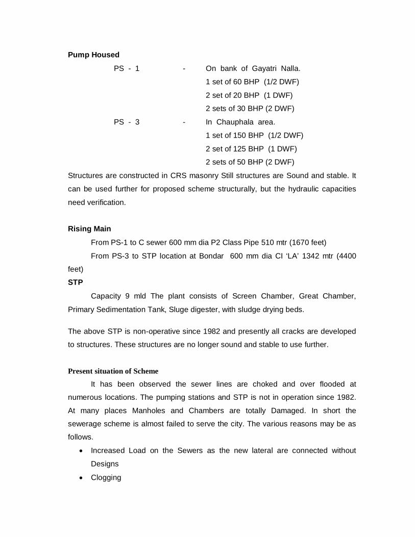
Pump Housed
PS - 1 - On bank of Gayatri Nalla.
1 set of 60 BHP (1/2 DWF)
2 set of 20 BHP (1 DWF)
2 sets of 30 BHP (2 DWF)
PS - 3 - In Chauphala area.
1 set of 150 BHP (1/2 DWF)
2 set of 125 BHP (1 DWF)
2 sets of 50 BHP (2 DWF)
Structures are constructed in CRS masonry Still structures are Sound and stable. It
can be used further for proposed scheme structurally, but the hydraulic capacities
need verification.
Rising Main
From PS-1 to C sewer 600 mm dia P2 Class Pipe 510 mtr (1670 feet)
From PS-3 to STP location at Bondar 600 mm dia CI ‘LA’ 1342 mtr (4400
feet)
STP
Capacity 9 mld The plant consists of Screen Chamber, Great Chamber,
Primary Sedimentation Tank, Sluge digester, with sludge drying beds.
The above STP is non-operative since 1982 and presently all cracks are developed
to structures. These structures are no longer sound and stable to use further.
Present situation of Scheme
It has been observed the sewer lines are choked and over flooded at
numerous locations. The pumping stations and STP is not in operation since 1982.
At many places Manholes and Chambers are totally Damaged. In short the
sewerage scheme is almost failed to serve the city. The various reasons may be as
follows.
Increased Load on the Sewers as the new lateral are connected without
Designs
Clogging
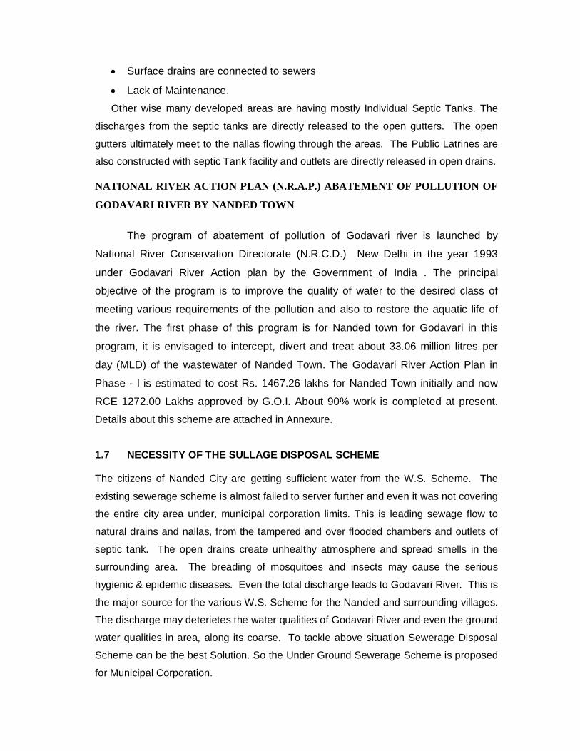
Surface drains are connected to sewers
Lack of Maintenance. Other wise many developed areas are having mostly Individual Septic Tanks. The
discharges from the septic tanks are directly released to the open gutters. The open
gutters ultimately meet to the nallas flowing through the areas. The Public Latrines are
also constructed with septic Tank facility and outlets are directly released in open drains.
NATIONAL RIVER ACTION PLAN (N.R.A.P.) ABATEMENT OF POLLUTION OF
GODAVARI RIVER BY NANDED TOWN
The program of abatement of pollution of Godavari river is launched by
National River Conservation Directorate (N.R.C.D.) New Delhi in the year 1993
under Godavari River Action plan by the Government of India . The principal
objective of the program is to improve the quality of water to the desired class of
meeting various requirements of the pollution and also to restore the aquatic life of
the river. The first phase of this program is for Nanded town for Godavari in this
program, it is envisaged to intercept, divert and treat about 33.06 million litres per
day (MLD) of the wastewater of Nanded Town. The Godavari River Action Plan in
Phase - I is estimated to cost Rs. 1467.26 lakhs for Nanded Town initially and now
RCE 1272.00 Lakhs approved by G.O.I. About 90% work is completed at present. Details about this scheme are attached in Annexure.
1.7 NECESSITY OF THE SULLAGE DISPOSAL SCHEME The citizens of Nanded City are getting sufficient water from the W.S. Scheme. The
existing sewerage scheme is almost failed to server further and even it was not covering
the entire city area under, municipal corporation limits. This is leading sewage flow to
natural drains and nallas, from the tampered and over flooded chambers and outlets of
septic tank. The open drains create unhealthy atmosphere and spread smells in the
surrounding area. The breading of mosquitoes and insects may cause the serious
hygienic & epidemic diseases. Even the total discharge leads to Godavari River. This is
the major source for the various W.S. Scheme for the Nanded and surrounding villages.
The discharge may deterietes the water qualities of Godavari River and even the ground
water qualities in area, along its coarse. To tackle above situation Sewerage Disposal
Scheme can be the best Solution. So the Under Ground Sewerage Scheme is proposed
for Municipal Corporation.
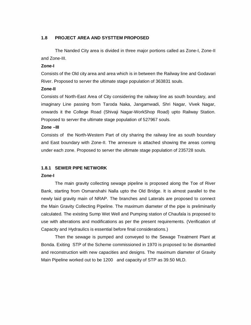
1.8 PROJECT AREA AND SYSTTEM PROPOSED
The Nanded City area is divided in three major portions called as Zone-I, Zone-II
and Zone-III.
Zone-I Consists of the Old city area and area which is in between the Railway line and Godavari
River. Proposed to server the ultimate stage population of 363831 souls.
Zone-II Consists of North-East Area of City considering the railway line as south boundary, and
imaginary Line passing from Taroda Naka, Jangamwadi, Shri Nagar, Vivek Nagar,
onwards it the College Road (Shivaji Nagar-WorkShop Road) upto Railway Station.
Proposed to server the ultimate stage population of 527967 souls.
Zone –III
Consists of the North-Western Part of city sharing the railway line as south boundary
and East boundary with Zone-II. The annexure is attached showing the areas coming
under each zone. Proposed to server the ultimate stage population of 235728 souls.
1.8.1 SEWER PIPE NETWORK Zone-I
The main gravity collecting sewage pipeline is proposed along the Toe of River
Bank, starting from Osmanshahi Nalla upto the Old Bridge. It is almost parallel to the
newly laid gravity main of NRAP. The branches and Laterals are proposed to connect
the Main Gravity Collecting Pipeline. The maximum diameter of the pipe is preliminarily
calculated. The existing Sump Wet Well and Pumping station of Chaufala is proposed to
use with alterations and modifications as per the present requirements. (Verification of
Capacity and Hydraulics is essential before final considerations.)
Then the sewage is pumped and conveyed to the Sewage Treatment Plant at
Bonda. Exiting STP of the Scheme commissioned in 1970 is proposed to be dismantled
and reconstruction with new capacities and designs. The maximum diameter of Gravity
Main Pipeline worked out to be 1200 and capacity of STP as 39.50 MLD.

Zone-II
The major area of Zone-II is developed in later 1980’s. Although the part of this
zone is sewered and connected to the B-sewer of existing scheme. Now it is proposed to
lay a Main Collecting Gravity Sewer Pipeline Originating from Workshop T-point
proceeding along Old Purna Road upto Naik Chowk. Further proposed to pass through
Sakhoji Nagar onwards downhill of Maltekdi. Branches and laterals from areas Sahayog
Nagar, Pirburhan Nagar, Ashok Nagar, Bhagya Nagar, Pornimanagar, Shobha Nagar,
Sunder Nagar, Anand Nagar, Sharda Nagar, Area around MGM college and Hanuman
Garh, Pandurang Nagar Khushal Singh Nagar and other surrounding area. Even the
area which is presently covered under B-sewer, proposed to diver to this sewer line.
STP is proposed beyond the proposed Railway Station of Maltekdi. The sewage
can be gravitationally conveyed upto STP sump if suitable land is obtained around
Maltekdi, as it slops naturally towards Asana River. The maximum diameter of Gravity
Main Pipeline worked out to be 1400 and capacity of STP as 57.00 MLD.
ZONE -III Part of this zone is presently served by A-sewer of exiting scheme. The newly
developed area Kabra Nagar, Deep Nagar, Dyaneshware Nagar, is proposed to sewer
in this Zone-III. Collecting Sewer Pipeline is proposed to lay along the Chunal Nalla. The
B-sewer and other proposed branches are proposed to connect the collecting main.
Sump and Pump house is proposed near the railway line in Lalwadi area. Then it can be
conveyed to the proposed STP-III in the fields of village Wadi Kd. The maximum
diameter of main works out to be 1000 mm and capacity of STP as 25.50 MLD.
1.8.2 SEWEAGE TREATMENT PLANTS AND DISPOSAL OF EFFLUENT
Separate three Sewage Treatment Plants are proposed for Zone-I, II & III. The STP for
Zone-I is proposed at the existing STP at Bondar, for Zone-II in the fields of Mahalja
(Maltekadi) & for the Zone-III in the fields of Wadi kd. The capacities worked out are as
Zone –I - 39.50 mld
Zone – II - 57.00 mld
Zone –III - 25.50 mld
The effluent of the STP’s will be proposed to utilize for the irrigation provide to Private
Cultivators. The desired limits of Treated effluent must be having B.O.D. of 30 mg/lit or less
and suspended solids of 50 mg/lit or less for disposal into inland water bodies (As per the
CPHEEO Norms). And BOD 20 mg/l and SS 30 mg/l are desired of the effluent as per the
norms of Pollution Control Board.

1.9 COST ESTIMATES
The Cost estimates will be prepared based on Schedules of Rates of M.J.P., PWD
Aurangabad Region and M.C. CSR for for year 2005-2006. The Annual Over Burden on
the Scheme will be worked out as per standard practice and the Taxation Structure will
be reviewed to achieve the scheme, Self Supporting.

Chapter – 2
OBJECTIVES AND SCOPE OF CONSULTANCY ASSIGNMENT 2.1 Objectives
The main objective of the consultancy, concise statement of objectives as spelt out in Terms of Reference (TOR), are very clear. Consultants fully agree with these objectives. These objectives as given in TOR are reproduced as under:
2.1.1 To carry out detailed investigation and survey of proposed scheme for Area of Nanded-Waghala Municipal Limits North of Godavari River.
2.1.2 To carry out detailed engineering design for all elements of the proposed
underground drainage scheme prepare working drawing suitable for execution.
2.1.3 To prepare detailed cost estimates for the construction of the underground
drainage scheme. 2.2 Scope of consultancy
As per the scope of consultancy services as elaborated in TOR.
1. Reconnaissance survey of the project area and collection of available data from NWCMC/other authorities.
2. Carrying out detailed topographic survey and soil investigation of the
project area. 3. Finalisation of design norms based on guidelines of CPHEEO Manual
published by Ministry of Urban Development, Govt. of India and in discussion with KDMC authorities.
4. Planning of sewer zones considering topography, existing development,
land use proposed in DP, present waste water management practices etc.
5. Estimation of quantity and quality of sewage generated in the project area
for each zone based on population, water consumption for domestic wastewater.
6. Study of alternative technologies and sites for S.T.P., pumping stations, if
required and alternative alignments of pumping main and recycling/disposal facilities to arrive at most techno-economic feasible system.
7. Hydraulic & detailed design of complete sewerage system including
laterals, main sewers, pumping mains, preparation of L Section, sewer network plan, manhole locations, etc.
8. Hydraulic & detailed design of STP and recycling/disposal system.
9. Detailed estimate for sewerage system including pumping stations and
STPs based on current schedule of rates.
10. Financial analysis and review of financial aspects.
11. Suggest Institutional Strengthening and O&M System. 2.3 Earlier Submissions
The Pre-Feasibility Report for the Scheme was submitted. The Prefeasibility Report included the following: Study Objective & Scope of Work Approach & Methodology Design Norms for Sewerage System Priority Works The report was discussed in detail with the Engineers of M.J.P. and the Executive Engineer (Sewerage), KDMC. The important points are: a) MJP authority suggested part sewage to be treated for stream standards
wherever possible for reuse for horticulture and agriculture purpose and balance disposal into local streams or inland water bodies.
b) The use of submersible pumps may be proposed to the extent possible.

c) Ward wise population figures of 2001 census shall be used for projection of future population and the population projection should be correlative the under execution 6 village Water Supply Project of Nanded.
d) An infiltration allowance up to 10 percent of the wastewater flow shall be used for working out average wastewater flows.
e) Rate of water supply to be considered for design of Sewer network is as 140 lpcd.
Contents of Pre Feasibility were as follows: Objective & Scope of the Project Population Projections Waste Water flows Topographic surveys Design Parameters Selection Criteria for Treatment Process
Chapter - 3 POPULATION PROJECTIONS
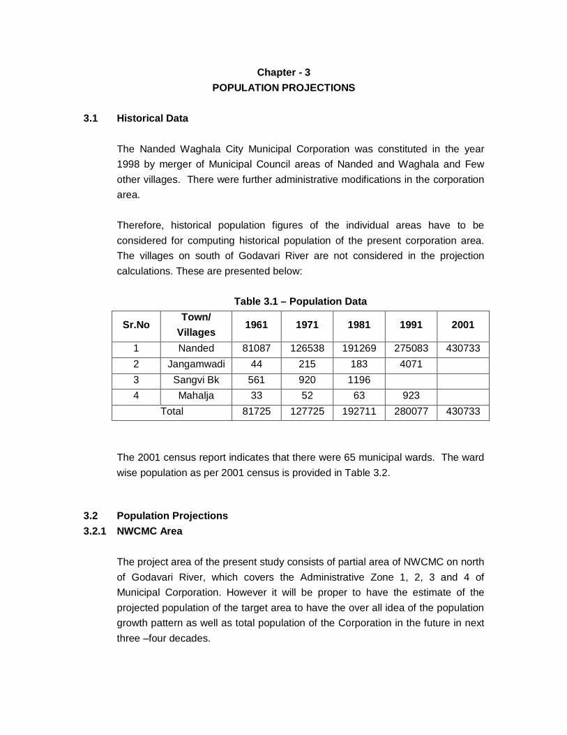
3.1 Historical Data
The Nanded Waghala City Municipal Corporation was constituted in the year 1998 by merger of Municipal Council areas of Nanded and Waghala and Few other villages. There were further administrative modifications in the corporation area. Therefore, historical population figures of the individual areas have to be considered for computing historical population of the present corporation area. The villages on south of Godavari River are not considered in the projection calculations. These are presented below:
Table 3.1 – Population Data
Sr.No Town/
Villages 1961 1971 1981 1991 2001
1 Nanded 81087 126538 191269 275083 430733 2 Jangamwadi 44 215 183 4071 3 Sangvi Bk 561 920 1196 4 Mahalja 33 52 63 923
Total 81725 127725 192711 280077 430733
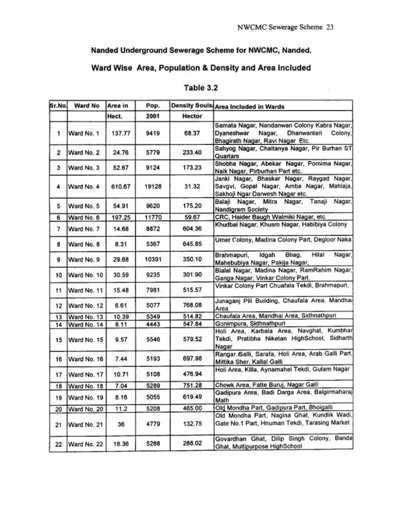
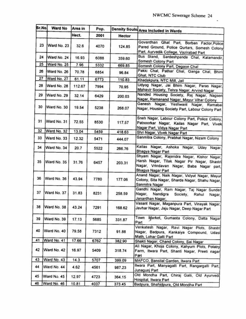
The 2001 census report indicates that there were 65 municipal wards. The ward wise population as per 2001 census is provided in Table 3.2.
3.2 Population Projections 3.2.1 NWCMC Area
The project area of the present study consists of partial area of NWCMC on north of Godavari River, which covers the Administrative Zone 1, 2, 3 and 4 of Municipal Corporation. However it will be proper to have the estimate of the projected population of the target area to have the over all idea of the population growth pattern as well as total population of the Corporation in the future in next three –four decades.
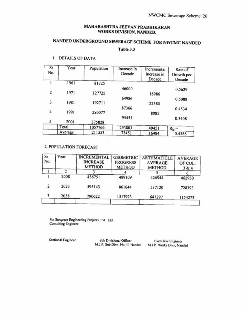
The population projections have been worked out by standard methods of the projection and compared among them selves. The standard methods used for projections are Arithmetic increase Geometric increase Incremental increase Linear projection Apart from the projections by conventional methods, various other factors have to be considered for realistic projections. These are : a) Saturation density as per Development Plan b) Proposed landuse pattern in individual Ward c) Setting up of new industrial areas d) Transportation facilities e) Land Characteristics f) Availability of civic amenities g) The ongoing latest Project of Pollution for Water Supply Project and
proposed Densities. Consultants have taken population of 2001as basis for the projection and projected the population with actual achieved growth rates of individual ward.
3.3 Projections for the Study area 3.3.1 Present Population
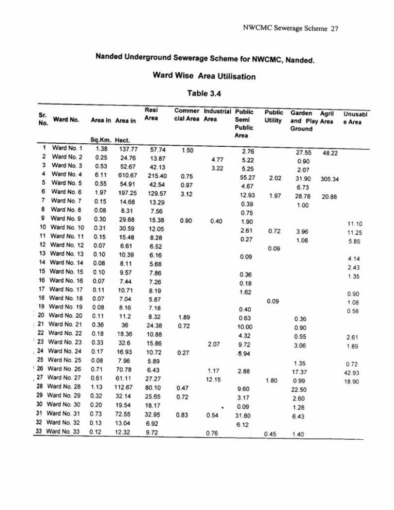
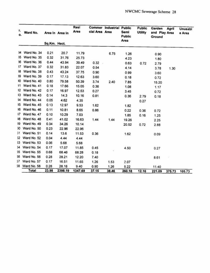
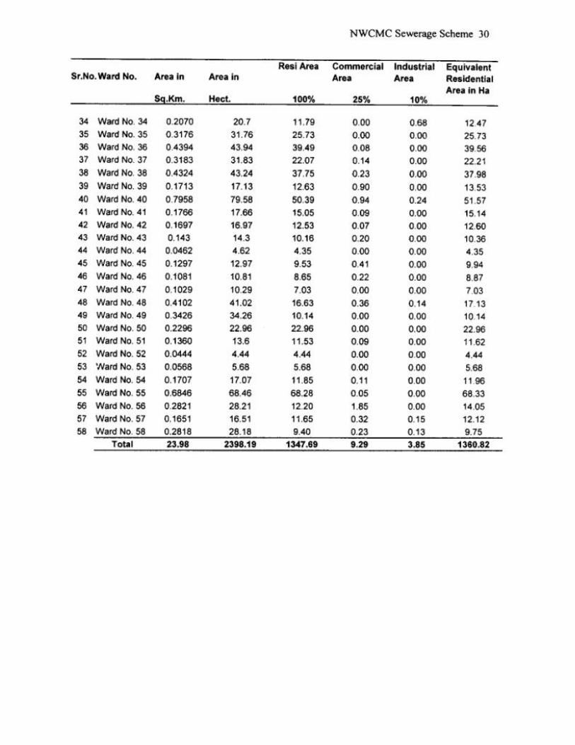
The proposed study area as described in the TOR comprises of four different parts. The ward numbers, areas and 2001 population are presented in Table 3.2.
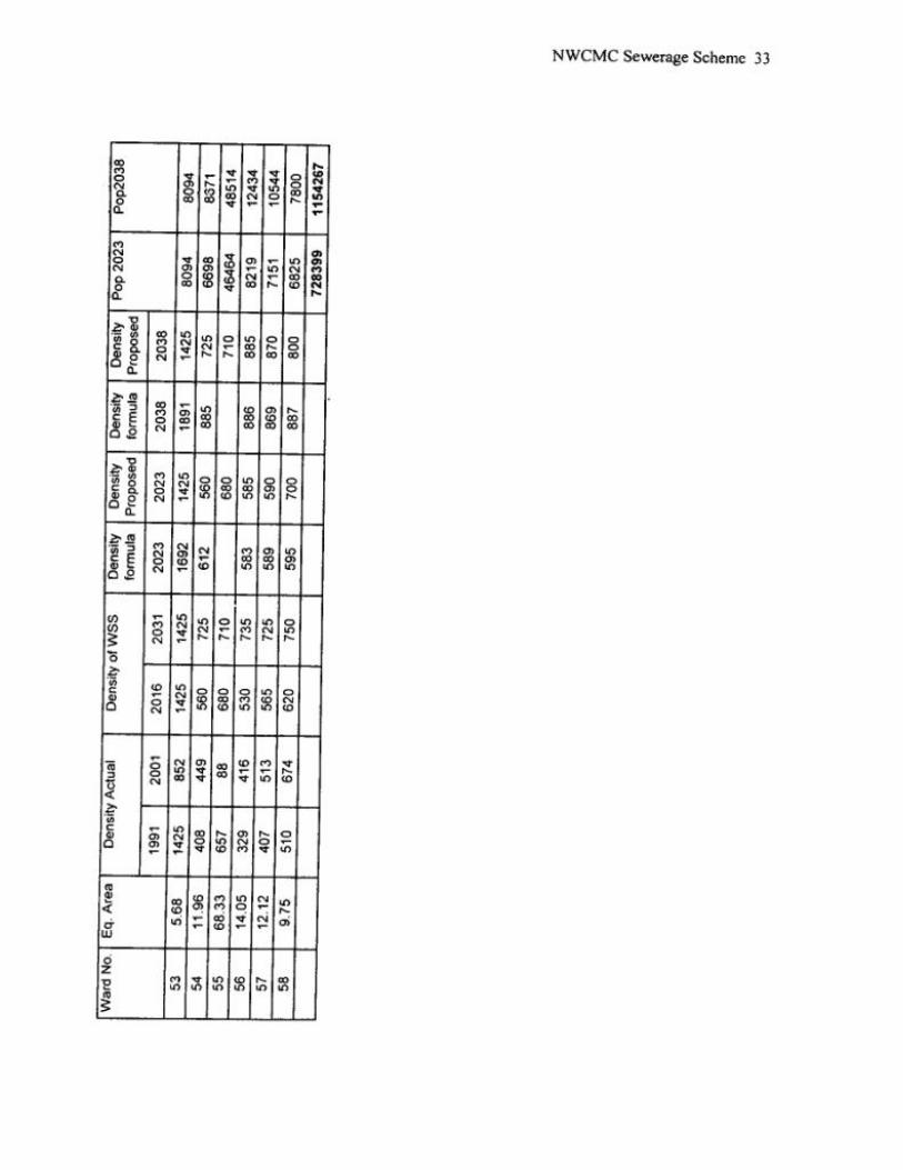
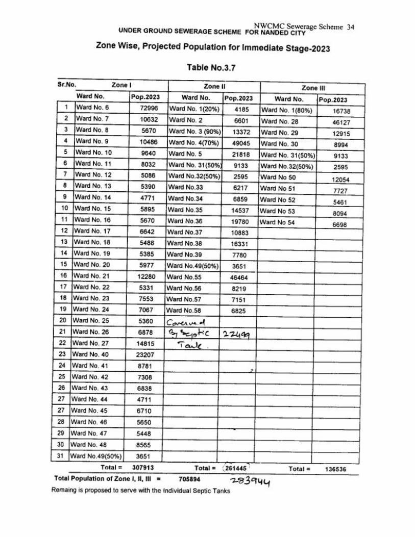
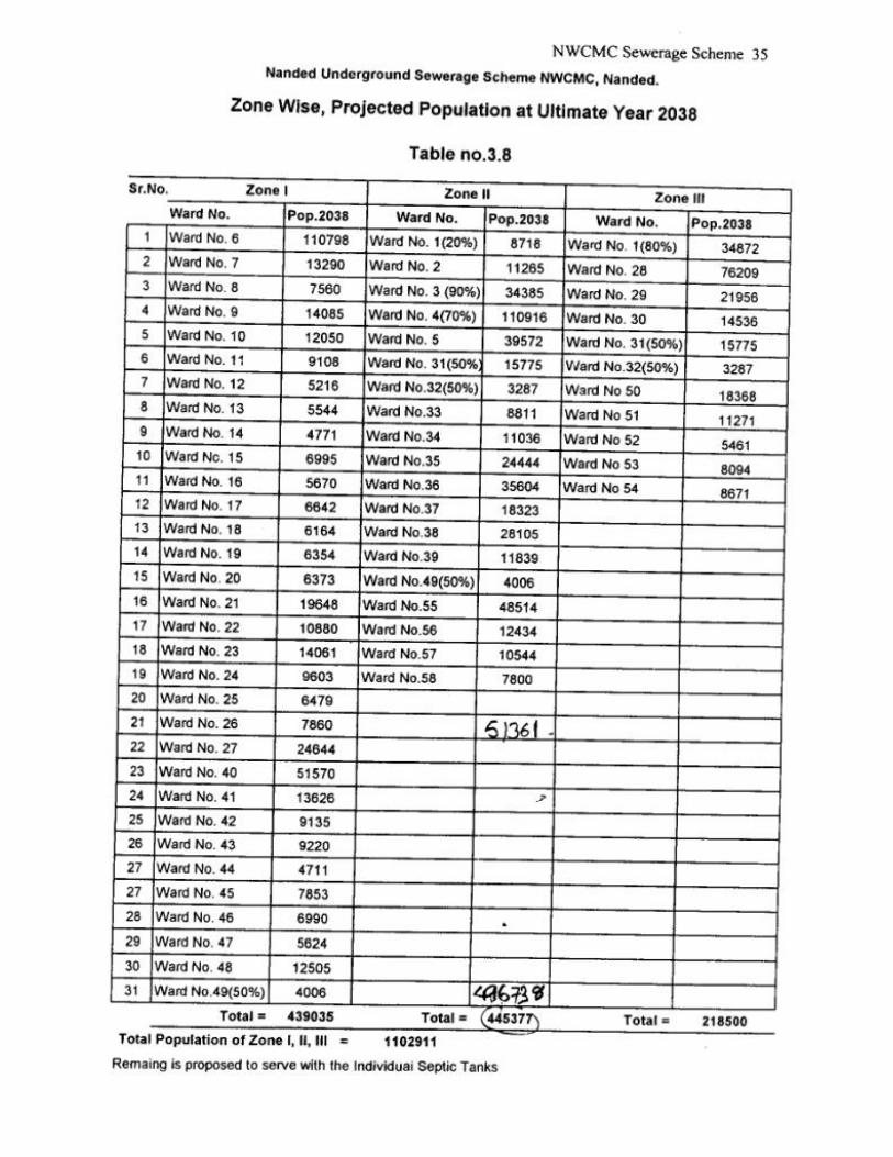
3.3.2 Projected Population in the Project Area Ward wise population projection considering the suggested growth rate have been worked out for the project area. Projected population for the Project Area is given in Table Saturation Density of maximum 1500 persons per Hectare has been considered. The calculations regarding the population projection are enclosed in Table 3.3 to 3.8


Chapter – 4 DESIGN PARAMETERS
4.1 General
The report included a separate chapter on ‘Design Parameters’. These design parameters had been discussed with MJP and have now been finalised. These parameters are the basis of all further work. Therefore, it is appropriate that these are included in the Detailed Project Report.
4.2 Design Criteria
The ‘Design Criteria’ have been finalised primarily on the basis of recommendations of the ‘Manual on Sewerage and Sewage Treatment’ by CPHEEO under the ministry of Urban Development, Government of India. The Design Criteria for the major system components of the ‘Sewerage Project’ are described below:
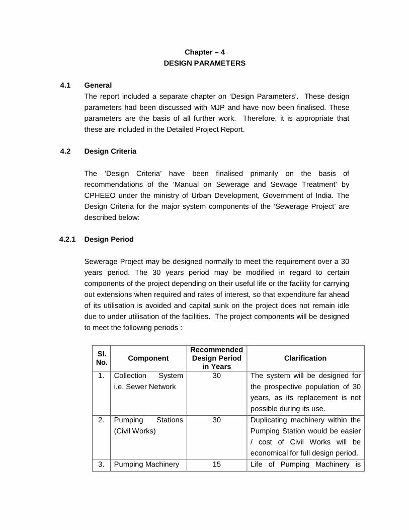
4.2.1 Design Period Sewerage Project may be designed normally to meet the requirement over a 30
years period. The 30 years period may be modified in regard to certain components of the project depending on their useful life or the facility for carrying out extensions when required and rates of interest, so that expenditure far ahead of its utilisation is avoided and capital sunk on the project does not remain idle due to under utilisation of the facilities. The project components will be designed to meet the following periods :
Sl. No. Component
Recommended Design Period
in Years Clarification
1. Collection System i.e. Sewer Network
30 The system will be designed for the prospective population of 30 years, as its replacement is not possible during its use.
2. Pumping Stations (Civil Works)
30 Duplicating machinery within the Pumping Station would be easier / cost of Civil Works will be economical for full design period.
3. Pumping Machinery 15 Life of Pumping Machinery is
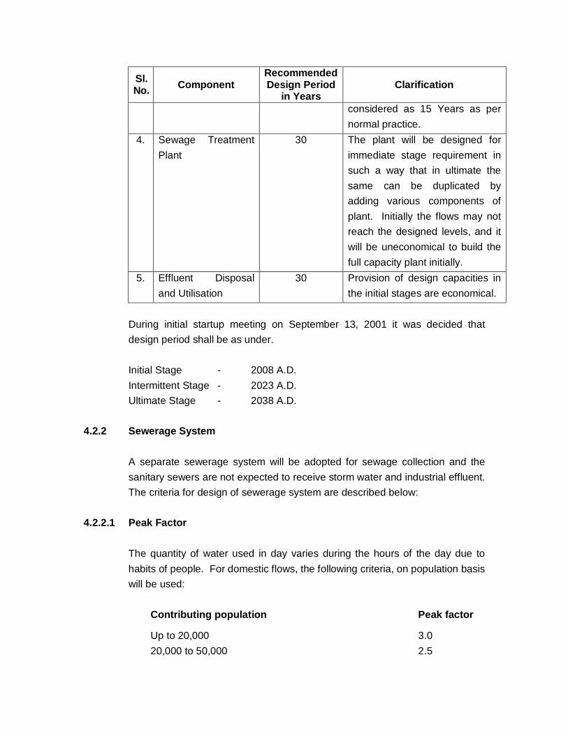
Sl. No. Component
Recommended Design Period
in Years Clarification
considered as 15 Years as per normal practice.
4. Sewage Treatment Plant
30 The plant will be designed for immediate stage requirement in such a way that in ultimate the same can be duplicated by adding various components of plant. Initially the flows may not reach the designed levels, and it will be uneconomical to build the full capacity plant initially.
5. Effluent Disposal and Utilisation
30 Provision of design capacities in the initial stages are economical.
During initial startup meeting on September 13, 2001 it was decided that
design period shall be as under. Initial Stage - 2008 A.D. Intermittent Stage - 2023 A.D. Ultimate Stage - 2038 A.D. 4.2.2 Sewerage System A separate sewerage system will be adopted for sewage collection and the
sanitary sewers are not expected to receive storm water and industrial effluent. The criteria for design of sewerage system are described below:
4.2.2.1 Peak Factor The quantity of water used in day varies during the hours of the day due to
habits of people. For domestic flows, the following criteria, on population basis will be used:
Contributing population Peak factor
Up to 20,000 3.0 20,000 to 50,000 2.5

50,000 to 750,000 2.25 Above 750,000 2.0 4.2.2.2 Infiltration The infiltration in to sewerage system shall be considered during flow
estimation. Estimate of the flow in sanitary sewer includes flows due to infiltration of water through the joints of pipes and through manholes. The quantity will depend on the workmanship in laying the sewers and the ground water table in the area. Sewers are designed for the peak discharges and all work for ground water infiltration is to be made for worst condition as safety measure. With better standards of workmanship and availability of push tight rubber joints for RCC pipes, these values should tend to minimum. The adopted values do not mean any relaxation on standard of water tightness requirement in clause 7.1.5 of CPHEEO Manual. As per the manual, the suggested estimate for infiltration for sewers laid below ground water table is:
Minimum Maximum
lpd / hectare area 5000 50000 lpd / km of sewer length 500 5000 lpd / manhole number 250 500
The project area experiences spells of heavy rainfall. Therefore the infiltration allowance up to 10% of average wastewater flow will be considered for the designs.
4.2.2.3 Minimum Size of Sewer Minimum diameter for public sewer shall not be less than 150 mm except hilly
regions. During startup meeting held on September 13, 2001, it was decided in concurrence with KDMC engineers to adopt minimum 250 mm diameter sewers for design purpose. Consultants have adopted sewers accordingly.
4.2.2.4 Capacity of Sewer (Depth of flow): All sewer are to be designed to flow maximum up to 0.8 full at ultimate peak
flow (clause 3.4.2.6 page 49 of CPHEEO Manual).
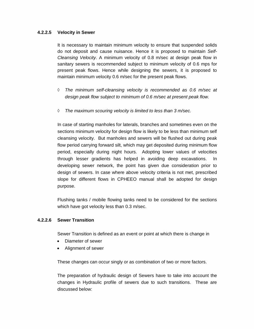
4.2.2.5 Velocity in Sewer It is necessary to maintain minimum velocity to ensure that suspended solids
do not deposit and cause nuisance. Hence it is proposed to maintain Self-Cleansing Velocity. A minimum velocity of 0.8 m/sec at design peak flow in sanitary sewers is recommended subject to minimum velocity of 0.6 mps for present peak flows. Hence while designing the sewers, it is proposed to maintain minimum velocity 0.6 m/sec for the present peak flows.
The minimum self-cleansing velocity is recommended as 0.6 m/sec at
design peak flow subject to minimum of 0.6 m/sec at present peak flow. The maximum scouring velocity is limited to less than 3 m/sec.
In case of starting manholes for laterals, branches and sometimes even on the
sections minimum velocity for design flow is likely to be less than minimum self cleansing velocity. But manholes and sewers will be flushed out during peak flow period carrying forward silt, which may get deposited during minimum flow period, especially during night hours. Adopting lower values of velocities through lesser gradients has helped in avoiding deep excavations. In developing sewer network, the point has given due consideration prior to design of sewers. In case where above velocity criteria is not met, prescribed slope for different flows in CPHEEO manual shall be adopted for design purpose.
Flushing tanks / mobile flowing tanks need to be considered for the sections
which have got velocity less than 0.3 m/sec. 4.2.2.6 Sewer Transition
Sewer Transition is defined as an event or point at which there is change in Diameter of sewer Alignment of sewer These changes can occur singly or as combination of two or more factors. The preparation of hydraulic design of Sewers have to take into account the changes in Hydraulic profile of sewers due to such transitions. These are discussed below:
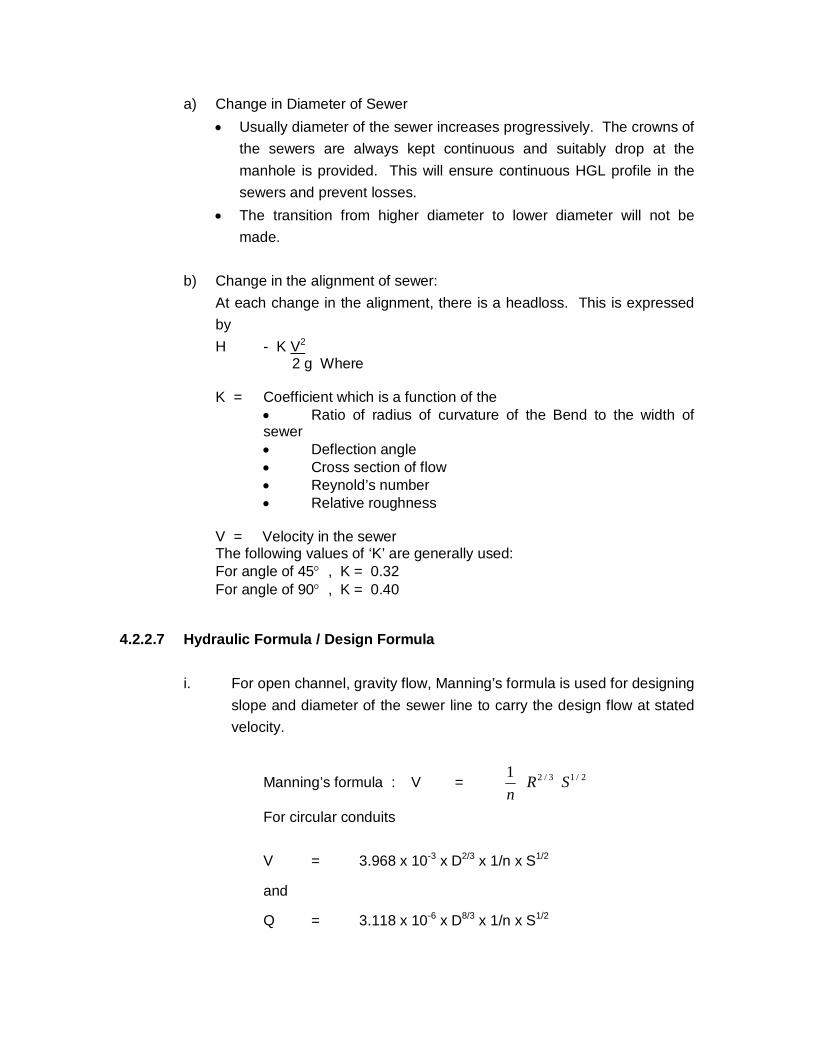
a) Change in Diameter of Sewer Usually diameter of the sewer increases progressively. The crowns of
the sewers are always kept continuous and suitably drop at the manhole is provided. This will ensure continuous HGL profile in the sewers and prevent losses.
The transition from higher diameter to lower diameter will not be made.
b) Change in the alignment of sewer:
At each change in the alignment, there is a headloss. This is expressed by H - K V2
2 g Where K = Coefficient which is a function of the
Ratio of radius of curvature of the Bend to the width of sewer Deflection angle Cross section of flow Reynold’s number Relative roughness
V = Velocity in the sewer
The following values of ‘K’ are generally used: For angle of 45 , K = 0.32 For angle of 90 , K = 0.40
4.2.2.7 Hydraulic Formula / Design Formula
i. For open channel, gravity flow, Manning’s formula is used for designing slope and diameter of the sewer line to carry the design flow at stated velocity.
Manning’s formula : V = 2/13/21 SRn
For circular conduits V = 3.968 x 10⁻³ x D2/3 x 1/n x S1/2
and
Q = 3.118 x 10⁻⁶ x D8/3 x 1/n x S1/2

Where, Q = Discharge in lps S = Slope of hydraulic gradient D = Internal Dia of the pipe in mm R = Hydraulic radius in m V = Velocity in mps n = Manning’s coefficient of roughness
The value of Manning’s co-efficient for different pipe materials are given in Table 3.4 of CPHEEO manual.
For cement concrete pipes, values of n are as follows:
Manning’s Co-efficient
Conduit Material Condition of Interior Surface
Good Fair Cement Concrete 0.013 0.015
Therefore for cement concrete pipes a reduction in the value of n has
been reported with increase in diameter. Value of n i.e. co-efficient of roughness, are adopted as 0.015 for pipes
below 600 mm diameter & 0.013 for concrete pipes equal to & above 600 mm diameter.
ii. Hazen – Williams Formula is used for the pressure flow and is expressed
as follows: V = 0.849 C R0.63 S0.54 For circular conduits, the expression becomes V = 4.567 x 10⁻³ C D0.63 S0.54 and Q = 1.292 x 10⁻⁵ C D2.63 S0.54 Where
Q = Discharge in cum per hour D = Internal diameter of pipe in mm V = Velocity in mps R = Hydraulic Radius in m S = Slope of Hydraulic Gradient and C = Hazen – Williams Co-efficient
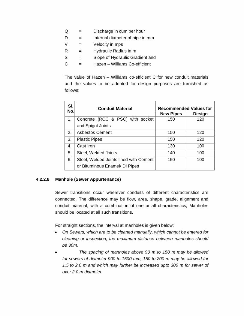
The value of Hazen – Williams co-efficient C for new conduit materials and the values to be adopted for design purposes are furnished as follows:
Sl. No. Conduit Material
Recommended Values for New Pipes Design
1. Concrete (RCC & PSC) with socket and Spigot Joints
150 120
2. Asbestos Cement 150 120 3. Plastic Pipes 150 120 4. Cast Iron 130 100 5. Steel, Welded Joints 140 100 6. Steel, Welded Joints lined with Cement
or Bituminous Enamel/ DI Pipes 150 100
4.2.2.8 Manhole (Sewer Appurtenance) Sewer transitions occur wherever conduits of different characteristics are
connected. The difference may be flow, area, shape, grade, alignment and conduit material, with a combination of one or all characteristics, Manholes should be located at all such transitions.
For straight sections, the interval at manholes is given below:
On Sewers, which are to be cleaned manually, which cannot be entered for cleaning or inspection, the maximum distance between manholes should be 30m.
The spacing of manholes above 90 m to 150 m may be allowed for sewers of diameter 900 to 1500 mm, 150 to 200 m may be allowed for 1.5 to 2.0 m and which may further be increased upto 300 m for sewer of over 2.0 m diameter.

The circular manholes can be provided for all depths starting from 0.9 m. The internal diameter of circular manholes may be kept as following for varying depths (Clause 4.2.1.2 of CPHEEO Manual)
Sr. No. Depth Diameter of Manhole
1. 0.90 m to 1.65 m 900 mm 2. 1.65 m to 2.30 m 1200 mm 3. 2.30 m to 9.00 m 1500 mm 4. 9.00 m to 14.00 m 1800 mm
The size of manhole covers should be such that there should be clear opening
of not less than 560 mm diameters for manholes exceeding 0.9 m depth (Clause 4.2.1.3 of CPHEEO Manual). All sewers above 450 mm diameter shall be provided with a scrapper manhole at interval not exceeding 120 m.
4.2.2.9 Type of Materials:
i. Precast RCC concrete pipes to be used for medium to large size diameter in KDMC project. Non-pressure pipes (NP pipes) to be used for gravity sewers. Non-pressure pipes shall conform to IS:458 – 1988. Advantage of RCC pipes are easy availability of required strength, ease of construction, economy , etc.
ii. For pumping mains, the generally available materials are CI, MS, DI,
PSC, GRP, HDPE, etc. Among these available pipe materials CI, MS & DI are commonly adopted for their advantageous characteristics. These can be laid speedily, are durable and have proven past records. An economic analysis, comparing CI, DI & MS pipes shall be carried out & most suitable and economical combination of diameter and pipe material shall be adopted.
4.2.3 Pumping Stations i. Dry Well:
The size of dry well should be adequate for the number of pumps. Allowance should also be made for future requirements so that additional or large pumps can be installed. As in most of the pumping stations

submersible pumps are to be provided, therefore generally dry wells are not required.
ii. Wet Well: The size of the wet well is influenced by the storage capacity to be
provided. The shape of well and the detention time period shall be provided such that deposition of solids is avoided and sewage does not turn septic. The capacity of the well be kept such that for any combination of inflow and pumping, the cycle of operation for each pump will not be less than 5 minutes and the maximum detention period in the wet well will not exceed 30 minutes of average flow.
iii. Pumps: The capacity of the pumps shall be adequate to meet the peak rate of
flow with 50% standby. The capacity of pump is usually stated in terms of Dry Weather Flow (DWF), estimated for the pumping station. The general practice is to provide 3 pumps for a small capacity pumping station comprising / pumps of 1 DWF, 1 of 2 DWF, and 1 of 3 DWF capacity. For large capacity pumping stations, 5 Pumps are usually provided comprising 2 of ½ DWF, 2 of 1 DWF and 1 of 3 DWF capacity, including stand by.
iv. Material of Construction:
a. RCC M25 will be used as construction material for water retaining structures.
b. M20 grade concrete will be considered for other RCC work. c. Reinforcement of HYSD Steel.
4.2.4 Sewage Treatment 4.2.4. 1 Degree of Treatment :
As per Clause 10.9.4 on page 195 of CPHEEO manual, it is generally the objective of domestic waste water treatment plant to produce treated effluents having BOD5 of 30 mg/l or less and suspended solids of 50 mg/l or less for disposal into inland water bodies. MPCB guidelines shall also be considered

while deciding the degree of treatment. Other disposal standards in terms of BOD are as follows: - Disposal into sea/creek – 100 mg/l - Disposal on land for irrigation – 100 mg/l
4.2.4.2 Sewage Characteristics:
The important sewage characteristics are Colour, Odour, Temperature, pH, Solids, Nitrogen, Phosphates, Chlorides, BOD5, COD and Toxic Metals etc.
Chapter – 5 SITE INVESTIGATION
5.1 Field Survey
Before the commencement of actual instrument survey, a short duration reconnaissance survey had been conducted in the identified project areas, stretches of sewer lines, pumping mains, location of proposed pumping stations and Sewage Treatment Plants. For the identified stretches of sewer lines and pumping mains instrument survey consisted of i) Total Station traversing ii) Level survey combination with Tape and Compass. At first, traversing has been conducted in all the identified alignments of sewer lines / pumping mains. After necessary traverse computation, level survey was started. Levels in longitudinal direction have been taken at every 30 m interval and additional levels at every important features like humps, dips, obstacles, crossings, road, railways, rivers, etc. are met with. At road intersections levels have been taken at a closer interval. Details of existing nearby structures / geographical features are also collected. All relevant levels of the existing / ongoing system were taken.
5.1.1 Fixation of Bench Marks
Before conducting level survey along the sewer line / pumping main alignment, levels were carried to the different parts of the Nanded-Waghala Municipal Corporation area from the existing bench marks. The Reference Bench Mark used for this project is the River Gauge Stations Bottom in Godavari River on Old Bridge. With the help of these bench mark the Consultants have established Temporary Bench Marks (TBM) within the project area and all are established on existing permanent structures. Locations of the Benchmarks are shown on the Survey Drawings. The details of these bench marks will be given separately in the Project Report.
5.2 Soil Investigation
In order to ascertain the sub-soil classification and bearing capacities, subsoil investigation is carried out by taking trial pits/ trial bores upto 3.0 m depth or upto

soft rock in each of the proposed and existing pump house locations, at regular intervals along the alternative alignments of proposed trunk sewer lines and at the Sewage Treatment Plants locations. Details of Trial pits are submitted separately in Drawing Volume IV along with the Project Report. The contour map has been prepared for all four parts of the project area with 1.0 m contour interval depending upon the Topography of the Project Area. The base maps of the project area indicating roads, water bodies, railway line and other salient features and with contours have been prepared and are enclosed in Drawing Volume.

Chapter 6 PROJECT PLANNING
6.1 Project Area
Nanded-Waghala City Municipal Corporation consists of erstwhile old Nanded Municipal Council, Waghala Municipal Council and surrounding urbanisable villages around the town. Areas of Nanded and Waghala Municipal Councils have partially existing underground sewerage system. The Nanded town is having the existing scheme which is almost collapsed and over burdened. The CIDCO are of earlier Waghala Municipal Council is having sewage system. So the areas newly developed in Nanded Twon and alterations and modernations of existing system in the Nanded town is given priority. The area North of Godavari River of NWCMS is considered in the project area.
6.2 Project Planning
For project planning based on geographical consideration the entire area is divided into three zones as shown in the drawing. These zones are formed on the basis of their locations as detailed below:
a) Zone I
Old Nanded City having area, Itwara, Chaufala, Holi, Gadipura, Vajirabad, Gurudwara, Doctor Lane, Khadakpura, Ganga Chal, Pakki chal, Degloor Naka Area, Bilal Nagar etc. This the Municipal Corporation area bounded by Northern Part Godavari River and Railway Line.
b) Zone II This Zone II consists of Municipal Corporation Area Bounded by Railway Track and Main Road from East ward area of Railway Over Bridge Shivaji Nagar to Regional Work Shop. Gokul Nagar, Industrial Estate, Visava Nagar, Police Colony, Vidya Nagar, Vivek Nagar, Shri Nagar, Nizam Colony, Prabhat Nagar, Kailas Nagar, Ashok Nagar, Sahayog Nagar, Bhagya Nagar, Ananad Nagar, Hanuman Garh Area, Khushal Singh Nagar area, Vishunu Nagar, Datta Nagar, New Mondha, Baba Nagar etc. are included in this Zone II.
c) Zone III

This Zone II consists of Municipal Corporation Area Bounded by Railway Track and Main Road from West ward area of Railway Over Bridge Shivaji Nagar to Regional Work Shop. Shivaji Nagar, Mahavir Society, Lalwadi, Abedkar Nagar, Nanded Hsg. Society, Ganesh Nagar, Yeshawant Nagar, Labour Colony, Ramanand Nagar, Mayur Vihar, Kabra Nagar, Ambika Nagar, Deep Nagar, Dyaneshwar Nagar, Bajaj Nagar, Vaman Nagar etc. areas are included in the Zone III
6.3 Zone II: 6.3.1 Zone II is moderately populated area of Nanded-Waghala City Municpal
Corporation. This zone covers the Area of part of following wards no1, 3, 4, 31, 32 and 49 and complete area of Ward No. 2, 5, 33, 34, 35, 36, 37, 38, 39, 55, 56, 57 and 58. The total population project for this Zone II is 4,45,377 souls for the Ultimate year 2038. This zone includes area as mentioned earlier. It is observed that the zone consists of developing areas as well as few saturated areas. Wardwise present (2001) population density varies from 100 persons / ha to 600 person / ha in this zone. Ward No. 16, 43,44 and 50 are congested wards whereas ward no. 10 is orderly developed. Wardwise projected (year 2008, 2023 and 2038) population and population density of the project area is given in Table 3.6. Projected population and population densities of different wards show that most of these wards reach the permissible saturation level of 1500 persons / ha in the year 2038.
6.3.2 Formation of Sewerage Districts (Sectors) : Areas included in Zone II are further subdivided geographically for project design. Mainly four sub-zones are proposed with trunk mains leading towards the East. 1. Area North of Work Shop-Bhagya Nagar, Nagarjuna T-point Road. 2. Area entrapped between Work Shop-Bhagya Nagar, Nagarjuna T-point
Road and V.I.P. road.

3. Area along the V.I.P. road. 4. Area beyond Stadium Complex. 5. Area East side of Hingoli Road. Area 1, includes Sahayog Nagar, Bhagya Nagar, Vasant Nagar, Tilak Nagar, Anand Nagar upto Hanuman Garh, is proposed to serve by the Trunk main starting from Workshop and leading towards Nagarjuna T-Point. Area 2, includes Nizam Colony, Shri Nagar, Vivek Nagar, Vidya Nagar, Police Colony, Kailash Nagar, Shyam Nagar, Baba Nagar, Vasant Nagar, and part of Maganpura/ New Mondha. The truck main of this area is proposed to confluence with the truck main of Area 1 at Nagarjuna T-Point. Area 3, includes the majority area on either sides of V.I.P. road and the truck main is proposed along the V.I.P. road. Area 4, includes the area of Gokul Nagar, Industrial Estate, Vishnu nagar and Hamalpura. The truck main is proposed to start from Railway Station Square and will lead to Anna Bhau Sathe Square. The Truck Main of Area 3 is proposed to confluence with it at Anna Bhau Sathe Square and the it is proposed to lead towards the Mitra Nagar, via Datta Nagar. Area 5, includes comparatively newly developed area. This area is stil under development phase. Water Supply Scheme is proposed for the area and the distribution network is proposed in the phases of Nanded Water Supply scheme. The main sewer line is proposed along the Mitra Nagar Nalla and after crossing of Railway Line Near Mahalja it is proposed to lead to Sewage Pumping Station. All the pipes in the network are proposed of RCC NP-III.

Chapter – 7
SEWER SYSTEMS 7.1 Introduction
Sewers are provided to convey waste water from one location to another location under gravity and therefore are normally laid deep enough to receive entire flows from surrounding areas. Sewers must resist erosion and corrosion and its structural strength must be sufficient to carry backfill, impact, and live loads satisfactorily. The size and slope of sewer must be adequate for the flow to be carried and sufficient to prevent deposition of solids. Ease and economy of maintenance, safety to the personnel and the public during its life as well as during construction also must be considered. The important aspects of any sewer system are location, size, slope, and depth of sewer and sewer material and other appurtenances to be added such as manholes, junctions / vent pipes and other structures to minimize turbulence and save head loss and prevent deposits and obnoxious gases. The aim of design is not only to make the sewer system functional, but also build the system at low competitive cost ensuring durability to the life of the system. Generally the total available energy is utilised to maintain proper flow velocities in the sewers with minimum head loss. Hence the sewer system design is limited on one hand by hydraulic losses which must be within the available Head and on the other to maintain self cleansing velocities. Many a times it is difficult to meet both conditions specially due to wide variation in rate of flow. Where differences in elevations are insufficient to permit gravity flow, pumping may be required. The cost of construction, operation, and maintenance of pumping stations are compared with the cost of construction and maintenance of gravity sewers. Apart from the cost considerations the consequences of mechanical and electrical failures at pumping stations may also be considered, which may necessitate a gravity system even at a higher cost.
7.2 Layout of Systems The sewerage system layout involves the following steps i) Selection of an outlet or disposal point ii) Prescribing limits to the drainage valley or Zonal Boundaries iii) Location of Trunk and Main Sewers iv) Location of Pumping Stations if found necessary
In general the sewers will slope in the same direction as the street or ground surface and will be connected by Trunk Sewers. The discharge point may be a
treatment plant or a pumping station or a water course, a trunk or intercepting sewer. It is desirable to have discharge boundaries following the property limits. The boundaries of sub zones are on the basis of topography, economy or other practical consideration. Trunk and main sewers are located in the valleys. The most common location of sanitary sewer is in the centre of the street. A single sewer serves both sides of the street with approximately same length for each zone wise house connection. Considering all the alternatives sewers for each zone are designed and design are enclosed in Volume II. Summary of the Sewer network for each sector is given. The Existing laterals are proposed to utilize partially i.e. 25% of laterals will be reused in this scheme and damaged or chocked up laterals and Chambers are proposed to relay and reconstruct. Considering the heavy traffic and moving load on the streets it is observed that the brick chambers are damaging. So separate rate analysis is carried for the RCC Manhole Chambers and those are proposed in the scheme to improve the operational conditions. All efforts are taken to maintain the depth of excavation as far as possible less.

Chapter 8 SEWAGE PUMPING STATIONS
8.0 Need for Sewage Pumping Stations
In most of the urban towns grounds are undulating and ground slopes are in varying directions resulting in hollow pockets where sewage flows can be collected under gravity. Pumping stations are therefore necessary to lift sewage from different low lying areas to Sewage Treatment Plants (STP) for imparting treatment. In the project area it is observed that collected sewage from various low lying areas namely Sectors / Zones will have to be lifted to sewage treatment plants by providing sewage pumping stations at suitable places. The STP for Zone II is proposed in the fields near by Mahalja, the reservation of those lands are shown in DP. The pumping station is also proposed near by the nalla.
8.1 Civil Works:
It is proposed to construct sump well in RCC (M-25) and overhead pump houses in B.B. masonry. New sewage pumping stations have been considered with rectangular wet well and dry well. rectangular pump house / switch room on top of wet well.
Storage Capacity / Wet Well Capacity: The capacity of the wet well is reckoned between the level at which air effects the suction line of the pump of minimum duty installed in the pump house and the designed sewage level in the incoming sewer i.e. the portion of the well below the upper most starting point and the lower most stopping point.
The size of the wet well is to be kept such that with any combination of inflow and pumping, the cycle of operation for each pump will not be less than 5 minutes. Capacity of sump will not exceed 30 minutes detention in order to prevent sewage becoming septic. Capacity and levels of sump
are given in Table. The proposed capacity of Sump is proposed of 15 min of peak flow.
8.2 Pumping Machineries
8.2.1 Mechanical
1. The capacity of the pumps shall be adequate to meet the peak rate of flow with standby arrangements. Average flow conditions are of interest in that they indicate the conditions under which the station will usually operate.
2. Highest Sewage Level / High Water Level (HWL) :
High Water Level (HWL) to be fixed at 150 mm below the invert of the downstream of screen at screen chamber.
3. Silt accommodation depth has been considered approximately 200 mm (average) including slope.
4. Provision of the pumps to be accommodated in the wet well in
submersible condition. Required numbers for the present duties and one number for future expansion and other accessories including functional requirements. Capacity of the future pump to be taken the maximum capacity of the present pump provided.
5. Medium screens in duplicate with a clear opening of 40 to 50 mm
between the bars for manually cleaned type shall be provided before the wet well.
The effective area of opening of the screen (which is the vertical projected area of the screen openings from the invert of the Channel to the flow line) will be such as to produce a velocity through the screen opening not exceeding 0.9 m/sec. at maximum expected flow i.e. peak flow. The screens shall conform to IS:6280.
6. Delivery openings of the pumps shall not be less than 100 mm and the pumps shall be capable of passing a ball of at least 80 mm
diameter for all dry-pit pumps, for submersible pumps, however, smaller diameter of ball passage may be allowed.
7. Delivery pipes are designed to have maximum velocities of 1.5 and
2.5 mps respectively wherever techno-economically possible, and as per availability of standard sizes. The delivery pipes of pumps are connected with the pumps through reducer / enlarger immediately before and after the pumps so as to restrict the velocity of sewage both in the pipelines at suction and delivery side. Each suction pipe shall be provided with a bell-mouth at its end. One number sluice and one number non-return for each pump.
8. Valves are provided on delivery side of each pump to allow proper
maintenance of pump.
9. In deciding the type of prime mover to be used, the following points are considered :
(a) Low cost (b) Suitable (c) Simplicity and ruggedness of construction
Considering the above, electrical drive is best for sewage pumping station. It is good practice from maintenance point of view to restrict the speed of pump to 750 rpm or 500 rpm for smaller units, but considering the initial cost and replacement facility the speed of the motor is taken as 1200 rpm (sym.) in general. A diesel standby unit is provided to meet the requirements (average flow capacity and lighting load) in case of power failure.
10. For headloss calculations, for pipe fittings "Hydraulic Institute
Standards" are followed and for straight pipes Hazen-William's formula is followed taking 'C' = 100. (All pipes and specials' materials are of Cast Iron).
11. Centrifugal Sewage pumps are considered.
12. Pumping station is proposed to be equipped with level indicators, automatic control systems with annunciation, pressure gage etc.
13. Pump Room / Switch Room is provided with required capacity of
H.O.T. / Monorail with chain pulley block for hoisting the equipments for maintenance.
14. Suitable by-pass arrangement with proper size of sluice valve is
provided in all pumping stations, for maintenance purpose. In case of pumping stations having influent sewer well below the mean sea level the bypass is provided at the suitable location on upstream of the influent sewer.
15. One number sump pump is provided in each pumping station to
drain out seepage and leakage water.
16. For pumping stations step down transformer is proposed. 8.2.2 Electrical System (General)
1. For all stations having installed load more than 100 KVA will have 11.0 KV supply and required capacity of transformer will be installed.
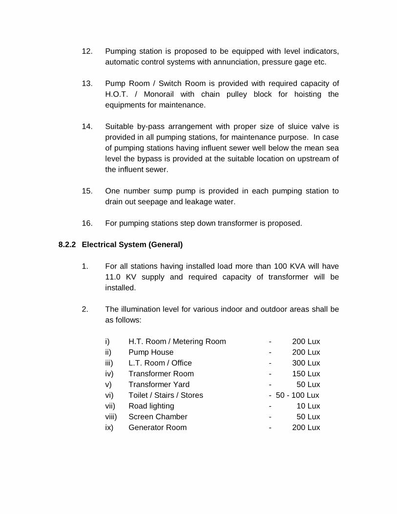
2. The illumination level for various indoor and outdoor areas shall be
as follows:
i) H.T. Room / Metering Room - 200 Lux ii) Pump House - 200 Lux iii) L.T. Room / Office - 300 Lux iv) Transformer Room - 150 Lux v) Transformer Yard - 50 Lux vi) Toilet / Stairs / Stores - 50 - 100 Lux vii) Road lighting - 10 Lux viii) Screen Chamber - 50 Lux ix) Generator Room - 200 Lux
3. Though all the motors will be operated from Motor Control Centre but start / stop push button switch will be provided near the motors for local control.
4. The earthing system shall be designed to ensure over all earth
resistance of one ohm.
5. Each sewage pump motor will be provided with required rating of capacitor / s to improve power factor of the pumps at existing P.S.)
8.2.3 Pump Operation
a) For proposed Pumping Station the pumps will be operated
automatically based on level of sewage in the wet well, but provision for manual operation will also be provided by auto / manual selector switch.
Pumps' starting will always be under submerged condition.
8.2.4 Sluice Gates
1 No. Sluice is provided on upstream and 1 No. sluice gate is provided on down stream side of screen chamber (2 Nos. screen chamber) to facilitate isolation and maintenance of screens for proposed pumping station.
8.2.5 Bar Screens Manually operated 2 Nos. bar screen (each in one screen chamber) are provided in the screen chambers both proposed pumping stations to prevent large size of solids entering the pumps. However, provision of installing mechanically operated screen has been kept in the proposed pumping station.
8.2.6 Instrumentation Electrically operated liquid level indicator, annunciation of liquid level in the wet well and automatic control of pumps, pressure gauges at delivery side of each pump and common header, hooter for abnormal high water level and low water level etc. will be provided.
8.2.7 Pumping Machinery

Centrifugal Sewage Pumps with accessories will be provided at Dry well for pumping station to pump the sewage. Details of pumps at each of the new proposed pumping stations for Phase-I (Year 2023) is as per the design enclosed in Design Statements.

1 Ground level of STP 353.00 Mtr.
2 Crown level of STP 356.00 Mtr.
3 Lowest level of Main Sewer 349.90 Mtr.
4 Depth of sewerage in wet well 5.00 Mtr.
5 Suction head of Pump 2.00 Mtr.
6 Lowest level of wet well 340.00 Mtr.
7 Total head on Pump (1-6) 13.00 Mtr.
MAHARASHTRA JEEVAN PRADHIKARAN WORKS DIVISION, NANDED
CALCULATION OF LEVELS
NANDED UNDERGROUND SEWERAGE SCHEME
NWCMC, NANDED
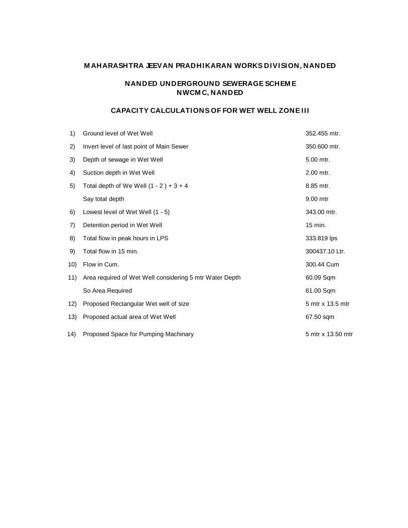
1) Ground level of Wet Well 352.455 mtr.
2) Invert level of last point of Main Sewer 350.600 mtr.
3) Depth of sewage in Wet Well 5.00 mtr.
4) Suction depth in Wet Well 2.00 mtr.
5) Total depth of We Well (1 - 2 ) + 3 + 4 8.85 mtr.
Say total depth 9.00 mtr
6) Lowest level of Wet Well (1 - 5) 343.00 mtr.
7) Detention period in Wet Well 15 min.
8) Total flow in peak hours in LPS 333.819 lps
9) Total flow in 15 min. 300437.10 Ltr.
10) Flow in Cum. 300.44 Cum
11) Area required of Wet Well considering 5 mtr Water Depth 60.09 Sqm
So Area Required 61.00 Sqm
12) Proposed Rectangular Wet well of size 5 mtr x 13.5 mtr
13) Proposed actual area of Wet Well 67.50 sqm
14) Proposed Space for Pumping Machinary 5 mtr x 13.50 mtr
CAPACITY CALCULATIONS OF FOR WET WELL ZONE III
MAHARASHTRA JEEVAN PRADHIKARAN WORKS DIVISION, NANDED
NANDED UNDERGROUND SEWERAGE SCHEMENWCMC, NANDED
TAL. DIST.
From :To :
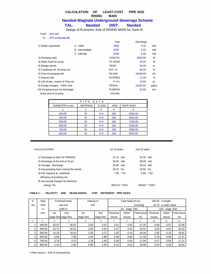
Year 1) Water requirement : A. Initial 2008 mld
B. Intermediate 2023 mldC. Ultimate 2038 mld
2) Pumping main LENGTH M 3) Static head for pump ST.HEAD M 4) Design period YEAR yr. 5) Combined eff. of pump set EFF. % % 6) Cost of pumping unit Rs./KW Rs 7) Interest rate INTEREST % 8) Life of elec. motors & Pmp set P.Yrs yr. 9) Energy charges KWH Unit P/KWH paise10) Pumping hours for discharge PUMPING- hrs at the end of 15 years HOURS
P I P E D A T A MATERIAL CLASS HWC RATE Rs/M
2 3 4DI K-9 100DI K-9 100DI K-9 100DI K-9 100DI K-9 100DI K-9 100
CALCULATIONS: 1st 15 years 2nd 15 years
1) Discharge at Start OF PERIOD 27.12 mld 32.55 mld 2) Discharge at the end of 15 yrs 32.55 mld 38.28 mld 3) Average Discharge 29.84 mld 35.42 mld 4) Ave.pumping hours during the period 18.33 hrs 18.50 hrs 5) KW required at combined 7.39 * H1 8.69 * H2 efficiency of pumping set 6) Ave.annual charges for electrical energy Rs. 954110 * KW1 963027 * KW2
TABLE 1 - VELOCITY AND HEADLOSSES FOR DIFFERENT PIPE SIZES
S. Pipe Total head (m) for 100.00 m length No. Size including 16.70 m static head
in mm. 1st 2nd 1st 2nd Frictional Other* Total losses Frictional Other* Total losses
stage flow stage flow stage flow stage flow losses losses H1 losses losses H21 2 3 4 5 6 7 8 9 10 11 12
1 400.00 42.07 56.81 3.60 4.23 4.21 0.42 21.33 5.68 0.57 22.952 450.00 23.71 32.01 2.84 3.34 2.37 0.24 19.31 3.20 0.32 20.223 500.00 14.19 19.16 2.30 2.71 1.42 0.14 18.26 1.92 0.19 18.814 600.00 5.84 7.88 1.60 1.88 0.58 0.06 17.34 0.79 0.08 17.575 700.00 2.76 3.72 1.18 1.38 0.28 0.03 17.00 0.37 0.04 17.116 800.00 1.44 1.94 0.90 1.06 0.14 0.01 16.86 0.19 0.02 16.91
* Other losses = 10% of frictional loss
2nd stage flow
Frictional Head Velocity in loss per m/s1000 m 1st stage flow
600.00 7649.00700.00 9256.00800.00 9876.00
400.00 5382.00450.00 5610.00500.00 7183.00
12.0015.00
14250.0020.00
DIAMETER in mm.1 5
0.308500.00
49.0030.0060.00
16039.00
Design of Economic Size of RISING MAIN for Zone-IIIWet wellSTP at Maralak Bk.
Discharge0.100.19
RISING MAINCALCULATION OF LEAST-COST PIPE SIZE
Nanded-Waghala Underground Sewerage SchemeNanded Nanded
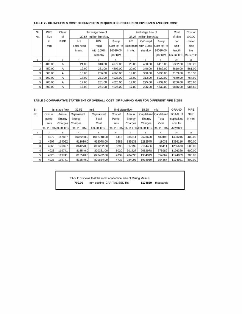
TABLE 2 - KILOWATTS & COST OF PUMP SETS REQUIRED FOR DIFFERENT PIPE SIZES AND PIPE COST
Sr. PIPE Class Cost Cost ofNo. Size of 32.55 million liters/day 38.28 million liters/day of pipe 100.00
in PIPE H1 KW Pump H2 KW req'd Pump per metermm Total head req'd Cost @ Rs Total head with 100% Cost @ Rs unit pipe
in mtr. with 100% 16039.00 in mtr. standby 16039.00 length line standby per KW per KW Rs. In THS. Rs. In THS
1 2 3 4 5 6 7 8 9 10 11
1 400.00 A 21.00 310.00 4972.00 23.00 400.00 6416.00 5382.00 538.202 450.00 A 19.00 281.00 4507.00 20.00 348.00 5582.00 5610.00 561.003 500.00 A 18.00 266.00 4266.00 19.00 330.00 5293.00 7183.00 718.304 600.00 A 17.00 251.00 4026.00 18.00 313.00 5020.00 7649.00 764.905 700.00 A 17.00 251.00 4026.00 17.00 295.00 4732.00 9256.00 925.606 800.00 A 17.00 251.00 4026.00 17.00 295.00 4732.00 9876.00 987.60
TABLE 3-COMPARATIVE STATEMENT OF OVERALL COST OF PUMPING MAIN FOR DIFFERENT PIPE SIZES
Sr. 32.55 mld 38.28 mld GRAND PIPENo. Cost of Annual Capitalised Capitalised Cost of Annual Capitalised Capitalised TOTAL of SIZE
pump Energy Energy Total Pump Energy Energy Total capitalised in mm.sets Charges Charges Cost sets Charges Charges Cost cost for
Rs. In THS.Rs. In THS. Rs. In THS. Rs. In THS. Rs. In THS.Rs. In THS.Rs. In THS. Rs. In THS. 30 years1 2 3 4 5 6 7 8 9 10 11
1 4972 147887 1007238.0 1012748.00 6416 385211 2623620 480498 1493246 400.002 4507 134052 913010.0 918078.00 5582 335133 2282545 418032 1336110 450.003 4266 126897 864278.0 869262.00 5293 317799 2164486 396411 1265673 500.004 4026 119741 815540.0 820331.00 5020 301427 2052978 375989 1196320 600.005 4026 119741 815540.0 820492.00 4732 284093 1934919 354367 1174859 700.006 4026 119741 815540.0 820554.00 4732 284093 1934919 354367 1174921 800.00
TABLE 3 shows that the most economical size of Rising Main is 700.00 mm costing CAPITALISED Rs. 1174859 thousands
1st stage flow of 2nd stage flow of
Ist stage flow IInd stage flow
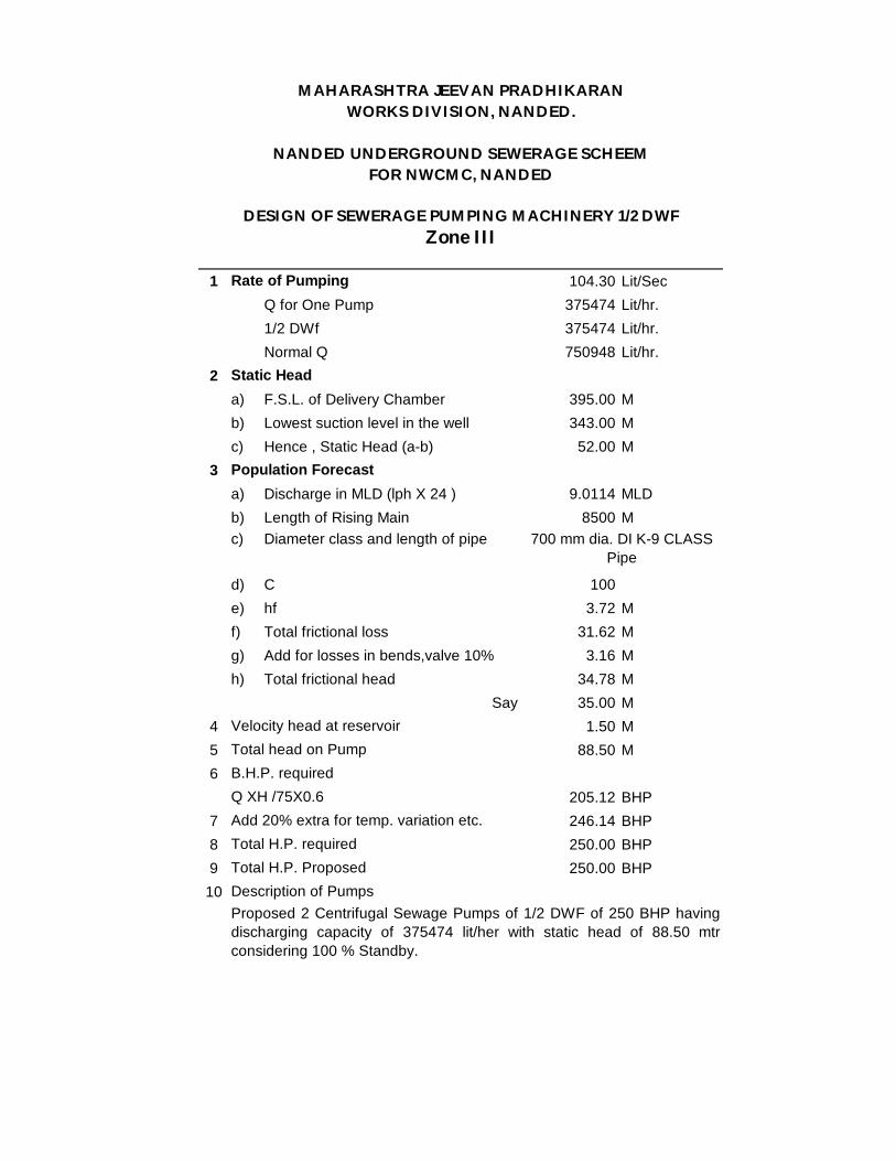
1 104.30 Lit/SecQ for One Pump 375474 Lit/hr.1/2 DWf 375474 Lit/hr.Normal Q 750948 Lit/hr.
2a) F.S.L. of Delivery Chamber 395.00 Mb) Lowest suction level in the well 343.00 Mc) Hence , Static Head (a-b) 52.00 M
3a) Discharge in MLD (lph X 24 ) 9.0114 MLDb) Length of Rising Main 8500 Mc) Diameter class and length of pipe
d) C 100e) hf 3.72 Mf) Total frictional loss 31.62 Mg) Add for losses in bends,valve 10% 3.16 Mh) Total frictional head 34.78 M
Say 35.00 M4 1.50 M5 88.50 M6
205.12 BHP7 246.14 BHP8 250.00 BHP9 250.00 BHP
10
B.H.P. requiredQ XH /75X0.6 Add 20% extra for temp. variation etc.
Static Head
Population Forecast
Velocity head at reservoir
Proposed 2 Centrifugal Sewage Pumps of 1/2 DWF of 250 BHP havingdischarging capacity of 375474 lit/her with static head of 88.50 mtrconsidering 100 % Standby.
DESIGN OF SEWERAGE PUMPING MACHINERY 1/2 DWF
Total H.P. required
700 mm dia. DI K-9 CLASS Pipe
Total H.P. ProposedDescription of Pumps
Total head on Pump
Zone III
FOR NWCMC, NANDED
MAHARASHTRA JEEVAN PRADHIKARANWORKS DIVISION, NANDED.
NANDED UNDERGROUND SEWERAGE SCHEEM
Rate of Pumping

1 208.60 Lit/SecQ for One Pump (1/3) 750948 Lit/hr.Peak Q (Q x 3) 2252844 Lit/hr.Normal Q 750948 Lit/hr.
2a) F.S.L. of Delivery Chamber 395.00 Mb) Lowest suction level in the well 343.00 Mc) Hence , Static Head (a-b) 52.00 M
3a) Discharge in MLD (lph X 24 ) 54.0683 MLDb) Length of Rising Main 8500 Mc) Diameter class and length of pipe
d) C 100e) hf 3.72 Mf) Total frictional loss 31.62 Mg) Add for losses in bends,valve 10% 3.16 Mh) Total frictional head 34.78 M
Say 35.00 M4 1.50 M5 88.50 M6
410.24 BHP7 492.29 BHP8 500.00 BHP9 500.00 BHP
10
B.H.P. requiredQ XH /75X0.6 Add 20% extra for temp. variation etc.
Static Head
Population Forecast
Velocity head at reservoir
Proposed 4 Centrifugal Sewage Pumps of 3 DWF of 500 BHP havingdischarging capacity of 750948 lit/hr with static head of 88.50 mtr 1/3Standby and which also accumulate the need of Pumps for Narmal flow.
DESIGN OF SEWERAGE PUMPING MACHINERY FOR 3 DWF
Total H.P. required
700 mm dia. DI K-9 CLASS Pipe
Total H.P. ProposedDescription of Pumps
Total head on Pump
Zone III
FOR NWCMC, NANDED
MAHARASHTRA JEEVAN PRADHIKARANWORKS DIVISION, NANDED.
NANDED UNDERGROUND SEWERAGE SCHEEM
Rate of Pumping

Chapter -9 SEWAGE TREATMENT PLANTS
9.1 Unit Operations & Processes
The removal of contaminants is generally brought by a sequential combination of various physical unit operations and biological unit process. The physical unit operations include screening, grit removal and sedimentation. The biological process can be broadly classified as: i. Suspended growth process ii. Attached growth process for both aerobic and anaerobic conditions. The unit operations and processes commonly employed in domestic wastewater treatment, their functions and units used to achieve these functions are stated in Table 9.1 below:
Table 9.1
Sl. No.
Unit Operations and Process
Functions
Treatment Devices
1. SCREENING Removal of large floating, suspended and settable solids.
Bar racks and screens of various description
2. GRIT REMOVAL Removal of inorganic suspended solids
Grit Chamber
3. PRIMARY SEDIMENTATION
Removal of organic and inorganic settable solids
Primary Sedimentation Tank
4. (a) AEROBIC BILOGICAL SUSPENDED GROWTH PROCESS
Conversion of colloidal, dissolved and residual suspended organic matter into settleable biofloc and stable in organic.
Activated sludge process units and its modifications, Waste Stabilisation Ponds, Aerated Lagoons
(b) AEROBIC BILOGICAL ATTACHED GROWTH PROCESS
Same as above Trickling Filter, Rotating Biological Contractor
5. ANAEROBIC BIOLOGICAL GROWTH PROCESSES
Conversion of organic matter into CH4 & CO2 and organic relatively stable organic residue
Anaerobic Filter, Fluid – Bed Submerged Media Anaerobic Reactor, Upflow Anaerobic Sludge Blanket Reactor, Anaerobic Rotating Biological Contractor.
6. ANAEROBIC STABILIZATION OF
Same as above Anaerobic Digester.

Sl. No.
Unit Operations and Process
Functions
Treatment Devices
ORGANIC SLUDGES 9.2 Treatment Alternatives
A large number of sewage treatment plants have been installed in India over a period of about 50 years and the process is essentially being biological with some primary treatment. Following is description of various alternatives available for Sewage treatment:
Biological Treatment Introduction
The objective of the biological treatment also termed, as secondary treatment is to remove soluble suspended and colloidal organic matter. This removal of organic matter is done by bringing active micro organism in contact with the waste water.
Depending upon the nature of dehydrogenation within the cell, the decomposition can be either. Aerobic (in the presence of molecular oxygen) Anaerobic (in the absence of molecular oxygen) In the case of aerobic decomposition, the hydrogen transfer combines with molecular oxygen in the dehydrogenation process In the anaerobic decomposition, the hydrogen transfer from the dehydrogenated compound to a hydrogen acceptor other than the molecular oxygen takes place. Aerobic Treatment Aerobic bacteria utilize organic matter as their food. Active biomass comprises of bacteria, algae, fungi, protozoa, rotifers, nematodes etc. These organisms in the presence of oxygen convert these biodegradable organic matters into non-biodegradable products like carbon dioxide and water.

Suspended Growth Aerobic Treatment
In suspended growth aerobic treatment, the micro-organisms remain in suspension. Major examples are activated sludge process and its various alternatives and aerated lagoons.
Activated Sludge Process
Activated sludge process is a continuous flow biological treatment system characterised by a suspension of aerobic micro – organisms, maintained in a relatively homogenous state by the regular mixing and turbulence in conjunction with aerobic process.
Basically, the activated sludge process uses micro – organisms in suspension to oxidise soluble and colloidal organics in the presence of molecular oxygen. During the oxidation process, a portion of the synthesized cells then undergo auto-oxidation (self-oxidation or endogenous respiration) in the aeration tank. Oxygen is required to support the synthesis and endogenous respiration reactions.
To operate the process in continuous basis, the solids generated must be separated in a clarifier, a portion is recycled to the aeration tank and excess sludge is withdrawn from the clarifier. The two basic units in the activated sludge system are aeration tank and a clarifier. Tapered Aeration Process Tapered aeration system involves provision of air in proportion in the BOD load in the aeration tank. It involves sizing of aeration facilities to provide the more air at the inlet and then decreasing the air provision along with the length of the tank as the oxygen demand decrease through the tank by making suitable arrangements. In other aspects, the system is same as conventional process. The basic aim of the system is to minimise the power.
Step Aeration Process
In this modification of activated sludge process, the raw wastewater is introduced at various points in the aeration tank. This tends to keep the oxygen demand fairly constant throughout the tank. Flexibility of operation is an important feature of this system. The oxygen demands more uniformly spread over the length of the

tank, which results in the better oxygen utilization. The multiple point introduction of wastewater results in the activated sludge with high absorptive properties so that soluble arganics are removed within a relatively short contact time. Higher organic loading are thus possible resulting in the reduced sizes of the aeration units.
Extended Aeration Process
This modification of activated sludge process is based on a low food to micro – organism ratio. As there is not much food (BOD) available for bacterial consumption, the micro – organism consume their own cell material for energy. At the end of this phase a non – biodegradable residue remains. The design of activated sludge process at a low organic loading results in a high degree of oxidation and minimum excess sludge production. However the volume of aeration basin becomes larger and the required capacity of aeration equipments is also more as extra oxygen is required for the endogenous respiration phase. At the same time, the burden of excess sludge handling is considerably reduced as the excess sludge production is substantially low and this excess sludge is highly oxidized posing no smell or odour. However extended aeration system needs considerable power consumption which involve higher energy cost.
Aerated Lagoons
In the aerated lagoons, air is introduced in the aeration basin. The hydraulic retention times are much longer than the activated sludge process and there is no return of sludge to the aeration tank. The mixing in the aeration basin is sufficient to distribute the oxygen throughout the basin but not sufficient enough to keep all the solids in suspension.
Trickling Filter
This process involves sprinkling of raw waste water over a fixed media. Normally when crushed rocks are used as the supporting media the filter is called as trickling filter and when synthetic media is used, the filter is called as biological tower. Advantage of using synthetic media is high surface area per unit volume provide by it (90 – 400 m2 / m3 of volume) with a corresponding high percentage of void ratio. Higher void ratio (upto 98%) provides substantial biological growth without inhabiting the passage of air supplying. Further it is possible to construct deeper beds (upto 10 m in height).

Trickling filters can be classified as low rate or high rate depending upon the hydraulic and organic loadings. Recirculation is often provided to increase the filter efficiency or to for the dilution of concentrated raw effluents.
Waste Stabilization Ponds
These are earthen basins designed to treat the wastewater naturally. Waste stabilization ponds are also called oxidation ponds. When land is plentiful and climatic conditions are favourable, waste stabilization ponds makes an attractive choice. Depending upon the biological activity, stabilization ponds can be classified into 3 categories :
Aerobic Ponds Facultative Ponds Anaerobic Ponds
Aerobic ponds are also called algae ponds. The depth of these ponds is about 1.0 to 1.3 m so that aerobic conditions can prevail in the pond. The oxygen required for treatment of the waste water supplied by algae photosynthesis and natural surface aeration. Facultative ponds basically have various zones of biological activity. Top aerobic zone, middle facultative zone and bottom anaerobic zone. The depth of the ponds varies from 2 to 4 m. Anaerobic Treatment
In anaerobic digestion, first higher weight organic molecular compounds (Polymers such as protein and starch) are converted into their monomers (a form which is assimilable for acidifying / fermentative bacteria) by bacteria. Secondly, these compounds are converted into lower molecular weight intermediate compounds. In this process, fermentative bacteria will ferment these monomers to organic acids, alcohols, carbon dioxide, hydrogen and ammonia, and acetogenic bacteria convert volatile fatty acids and alcohols into acetic acid and hydrogen. Thirdly, these intermediate compounds will be converted into simpler end products mainly methane and carbon dioxide by methanogenic bacteria.

Upflow Anaerobic Sludge Blanket (UASB) This is a suspended growth anaerobic process. Under this process a thick blanket of sludge is developed and kept under suspension by the upward velocity of waste water. Production of biogas also helps in proper mixing in the blanket. The waste water enters from the bottom. At the top portion of the UASB, there is a three phase separator viz. Liquid, solid and gas. Solids are recycled back to the system to avoid loss of any active biomass.
9.3 Selection of Treatment Alternatives
In order to select the treatment system for the project area, a number of factors are to be considered. A few of the major factors are : flow condition (quantity, quality, etc.) degree of treatment required depending upon the
influent quality and desired effluent quality. Extent of land available for sewage treatment Overall cost Operation and maintenance requirements vis-à-vis availability of such
facility. Ease of operation Manpower Requirement Climatic Condition Requisition of energy
Table 9.2 illustrates comparative merits & demerits between various alternative processes of sewage treatment plants respectively.
9.4 Selection of Process :
Cost and availability of land is the prime consideration in the selection of treatment method. It should include the cost of installation, capitalised cost of operation and maintenance taking into account interest charges and period of amortisation. Other factors that may influence are ease of construction and maintenance benefits that accrue from better environmental sanitation, location, and availability of land & topographical conditions. Type of STP will be decided after examining site conditions, land availability and suitability of process and quality of final effluents required for disposal.
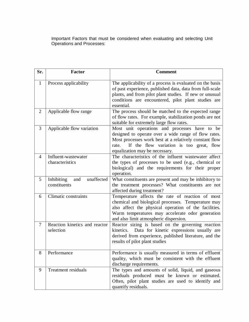
Important Factors that must be considered when evaluating and selecting Unit Operations and Processes:
Sr.
Factor Comment
1 Process applicability The applicability of a process is evaluated on the basis of past experience, published data, data from full-scale plants, and from pilot plant studies. If new or unusual conditions are encountered, pilot plant studies are essential.
2 Applicable flow range The process should be matched to the expected range of flow rates. For example, stabilization ponds are not suitable for extremely large flow rates.
3 Applicable flow variation Most unit operations and processes have to be designed to operate over a wide range of flow rates. Most processes work best at a relatively constant flow rate. If the flow variation is too great, flow equalization may be necessary.
4 Influent-wastewater characteristics
The characteristics of the influent wastewater affect the types of processes to be used (e.g., chemical or biological) and the requirements for their proper operation.
5 Inhibiting and unaffected constituents
What constituents are present and may be inhibitory to the treatment processes? What constituents are not affected during treatment?
6 Climatic constraints Temperature affects the rate of reaction of most chemical and biological processes. Temperature may also affect the physical operation of the facilities. Warm temperatures may accelerate odor generation and also limit atmospheric dispersion.
7 Reaction kinetics and reactor selection
Reactor sizing is based on the governing reaction kinetics. Data for kinetic expressions usually are derived from experience, published literature, and the results of pilot plant studies
8 Performance Performance is usually measured in terms of effluent quality, which must be consistent with the effluent discharge requirements.
9 Treatment residuals The types and amounts of solid, liquid, and gaseous residuals produced must be known or estimated. Often, pilot plant studies are used to identify and quantify residuals.
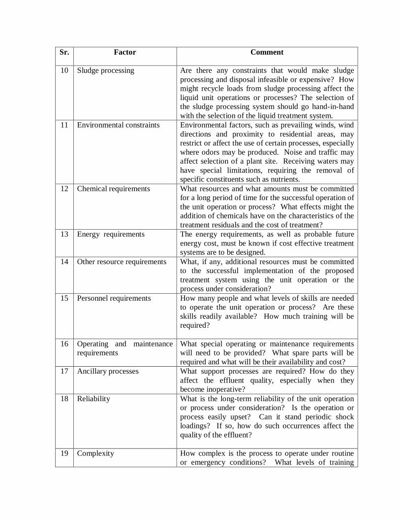
Sr.
Factor Comment
10 Sludge processing Are there any constraints that would make sludge processing and disposal infeasible or expensive? How might recycle loads from sludge processing affect the liquid unit operations or processes? The selection of the sludge processing system should go hand-in-hand with the selection of the liquid treatment system.
11 Environmental constraints Environmental factors, such as prevailing winds, wind directions and proximity to residential areas, may restrict or affect the use of certain processes, especially where odors may be produced. Noise and traffic may affect selection of a plant site. Receiving waters may have special limitations, requiring the removal of specific constituents such as nutrients.
12 Chemical requirements What resources and what amounts must be committed for a long period of time for the successful operation of the unit operation or process? What effects might the addition of chemicals have on the characteristics of the treatment residuals and the cost of treatment?
13 Energy requirements The energy requirements, as well as probable future energy cost, must be known if cost effective treatment systems are to be designed.
14 Other resource requirements What, if any, additional resources must be committed to the successful implementation of the proposed treatment system using the unit operation or the process under consideration?
15 Personnel requirements How many people and what levels of skills are needed to operate the unit operation or process? Are these skills readily available? How much training will be required?
16 Operating and maintenance requirements
What special operating or maintenance requirements will need to be provided? What spare parts will be required and what will be their availability and cost?
17 Ancillary processes What support processes are required? How do they affect the effluent quality, especially when they become inoperative?
18 Reliability What is the long-term reliability of the unit operation or process under consideration? Is the operation or process easily upset? Can it stand periodic shock loadings? If so, how do such occurrences affect the quality of the effluent?
19 Complexity How complex is the process to operate under routine or emergency conditions? What levels of training
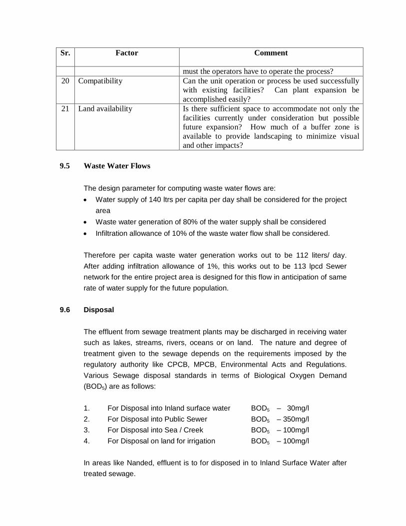
Sr.
Factor Comment
must the operators have to operate the process? 20 Compatibility Can the unit operation or process be used successfully
with existing facilities? Can plant expansion be accomplished easily?
21 Land availability Is there sufficient space to accommodate not only the facilities currently under consideration but possible future expansion? How much of a buffer zone is available to provide landscaping to minimize visual and other impacts?
9.5 Waste Water Flows
The design parameter for computing waste water flows are: Water supply of 140 ltrs per capita per day shall be considered for the project
area Waste water generation of 80% of the water supply shall be considered Infiltration allowance of 10% of the waste water flow shall be considered. Therefore per capita waste water generation works out to be 112 liters/ day. After adding infiltration allowance of 1%, this works out to be 113 lpcd Sewer network for the entire project area is designed for this flow in anticipation of same rate of water supply for the future population.
9.6 Disposal
The effluent from sewage treatment plants may be discharged in receiving water such as lakes, streams, rivers, oceans or on land. The nature and degree of treatment given to the sewage depends on the requirements imposed by the regulatory authority like CPCB, MPCB, Environmental Acts and Regulations. Various Sewage disposal standards in terms of Biological Oxygen Demand (BOD5) are as follows: 1. For Disposal into Inland surface water BOD5 – 30mg/l 2. For Disposal into Public Sewer BOD5 – 350mg/l 3. For Disposal into Sea / Creek BOD5 – 100mg/l 4. For Disposal on land for irrigation BOD5 – 100mg/l In areas like Nanded, effluent is to for disposed in to Inland Surface Water after treated sewage.
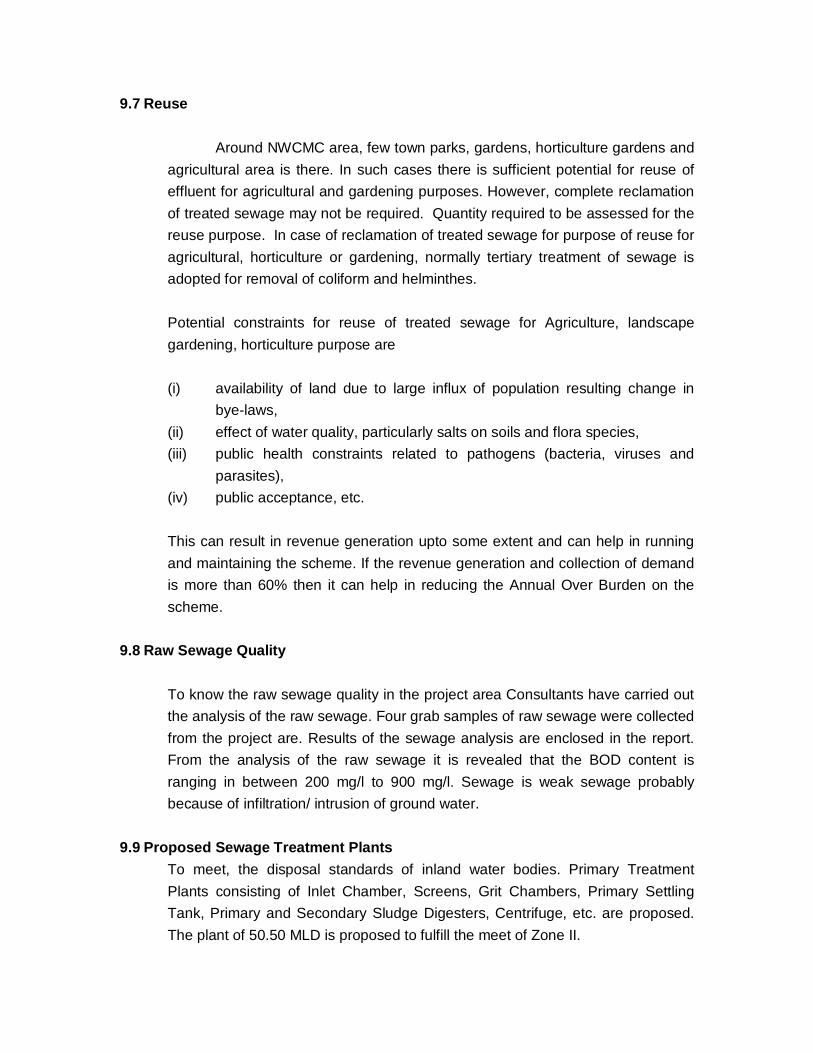
9.7 Reuse
Around NWCMC area, few town parks, gardens, horticulture gardens and agricultural area is there. In such cases there is sufficient potential for reuse of effluent for agricultural and gardening purposes. However, complete reclamation of treated sewage may not be required. Quantity required to be assessed for the reuse purpose. In case of reclamation of treated sewage for purpose of reuse for agricultural, horticulture or gardening, normally tertiary treatment of sewage is adopted for removal of coliform and helminthes.
Potential constraints for reuse of treated sewage for Agriculture, landscape gardening, horticulture purpose are (i) availability of land due to large influx of population resulting change in
bye-laws, (ii) effect of water quality, particularly salts on soils and flora species, (iii) public health constraints related to pathogens (bacteria, viruses and
parasites), (iv) public acceptance, etc. This can result in revenue generation upto some extent and can help in running and maintaining the scheme. If the revenue generation and collection of demand is more than 60% then it can help in reducing the Annual Over Burden on the scheme.
9.8 Raw Sewage Quality To know the raw sewage quality in the project area Consultants have carried out the analysis of the raw sewage. Four grab samples of raw sewage were collected from the project are. Results of the sewage analysis are enclosed in the report. From the analysis of the raw sewage it is revealed that the BOD content is ranging in between 200 mg/l to 900 mg/l. Sewage is weak sewage probably because of infiltration/ intrusion of ground water.
9.9 Proposed Sewage Treatment Plants To meet, the disposal standards of inland water bodies. Primary Treatment Plants consisting of Inlet Chamber, Screens, Grit Chambers, Primary Settling Tank, Primary and Secondary Sludge Digesters, Centrifuge, etc. are proposed. The plant of 50.50 MLD is proposed to fulfill the meet of Zone II.

Zone No. Area
1 Shivaji Nagar Zone 2 Ashok Nagar Zone 3 Itwara Zone. 4 Vajirabad Zone 5 Cidco Zone
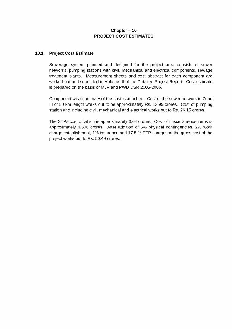
Chapter – 10 PROJECT COST ESTIMATES
10.1 Project Cost Estimate Sewerage system planned and designed for the project area consists of sewer
networks, pumping stations with civil, mechanical and electrical components, sewage treatment plants. Measurement sheets and cost abstract for each component are worked out and submitted in Volume III of the Detailed Project Report. Cost estimate is prepared on the basis of MJP and PWD DSR 2005-2006.
Component wise summary of the cost is attached. Cost of the sewer network in Zone
III of 50 km length works out to be approximately Rs. 13.95 crores. Cost of pumping station and including civil, mechanical and electrical works out to Rs. 26.15 crores.
The STPs cost of which is approximately 6.04 crores. Cost of miscellaneous items is
approximately 4.506 crores. After addition of 5% physical contingencies, 2% work charge establishment, 1% insurance and 17.5 % ETP charges of the gross cost of the project works out to Rs. 50.49 crores.

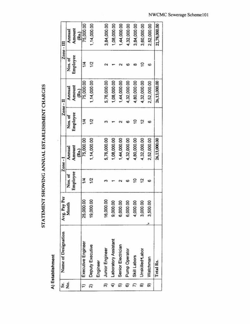
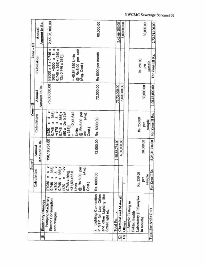
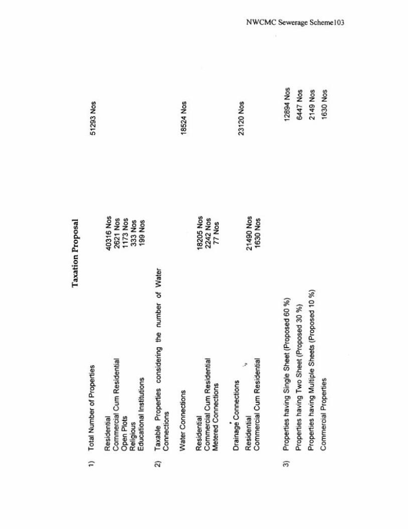

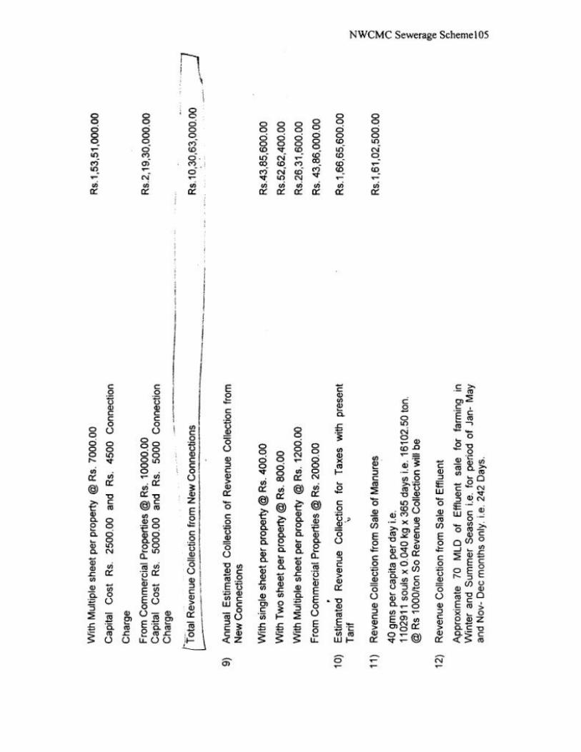
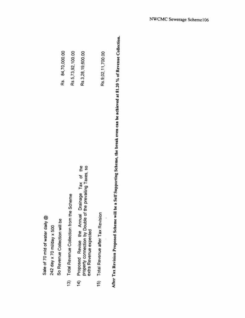
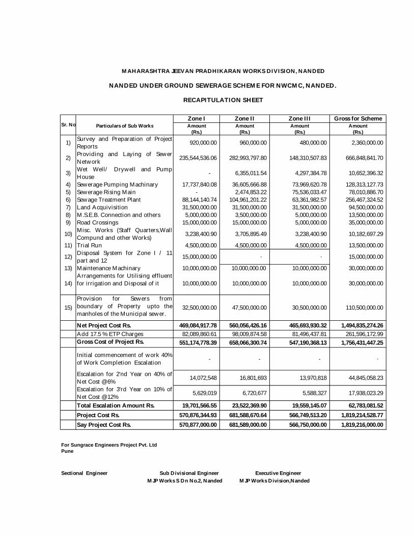
Zone I Zone II Zone III Gross for SchemeParticulars of Sub Works Amount Amount Amount Amount
(Rs.) (Rs.) (Rs.) (Rs.)
1) Survey and Preparation of ProjectReports 920,000.00 960,000.00 480,000.00 2,360,000.00
2) Providing and Laying of SewerNetwork 235,544,536.06 282,993,797.80 148,310,507.83 666,848,841.70
3) Wet Well/ Drywell and PumpHouse - 6,355,011.54 4,297,384.78 10,652,396.32
4) Sewerage Pumping Machinary 17,737,840.08 36,605,666.88 73,969,620.78 128,313,127.73 5) Sewerage Rising Main - 2,474,853.22 75,536,033.47 78,010,886.70 6) Sewage Treatment Plant 88,144,140.74 104,961,201.22 63,361,982.57 256,467,324.52 7) Land Acquivisition 31,500,000.00 31,500,000.00 31,500,000.00 94,500,000.00 8) M.S.E.B. Connection and others 5,000,000.00 3,500,000.00 5,000,000.00 13,500,000.00 9) Road Crossings 15,000,000.00 15,000,000.00 5,000,000.00 35,000,000.00
10) Misc. Works (Staff Quarters,WallCompund and other Works) 3,238,400.90 3,705,895.49 3,238,400.90 10,182,697.29
11) Trial Run 4,500,000.00 4,500,000.00 4,500,000.00 13,500,000.00
12) Disposal System for Zone I / 11part and 12 15,000,000.00 - - 15,000,000.00
13) Maintenance Machinary 10,000,000.00 10,000,000.00 10,000,000.00 30,000,000.00
14)Arrangements for Utilising effluentfor irrigation and Disposal of it 10,000,000.00 10,000,000.00 10,000,000.00 30,000,000.00
15)Provision for Sewers fromboundary of Property upto themanholes of the Municipal sewer.
32,500,000.00 47,500,000.00 30,500,000.00 110,500,000.00
Net Project Cost Rs. 469,084,917.78 560,056,426.16 465,693,930.32 1,494,835,274.26 Add 17.5 % ETP Charges 82,089,860.61 98,009,874.58 81,496,437.81 261,596,172.99 Gross Cost of Project Rs. 551,174,778.39 658,066,300.74 547,190,368.13 1,756,431,447.25
Initial commencement of work 40%of Work Completion Escalation - - - -
Escalation for 2'nd Year on 40% ofNet Cost @ 6% 14,072,548 16,801,693 13,970,818 44,845,058.23
Escalation for 3'rd Year on 10% ofNet Cost @ 12% 5,629,019 6,720,677 5,588,327 17,938,023.29
Total Escalation Amount Rs. 19,701,566.55 23,522,369.90 19,559,145.07 62,783,081.52 Project Cost Rs. 570,876,344.93 681,588,670.64 566,749,513.20 1,819,214,528.77 Say Project Cost Rs. 570,877,000.00 681,589,000.00 566,750,000.00 1,819,216,000.00
For Sungrace Engineers Project Pvt. LtdPune
Sectional Engineer Sub Divisional Engineer Executive Engineer MJP Works S Dn No.2, Nanded MJP Works Division,Nanded
Sr. No.
NANDED UNDER GROUND SEWERAGE SCHEME FOR NWCMC, NANDED.
RECAPITULATION SHEET
MAHARASHTRA JEEVAN PRADHIKARAN WORKS DIVISION, NANDED
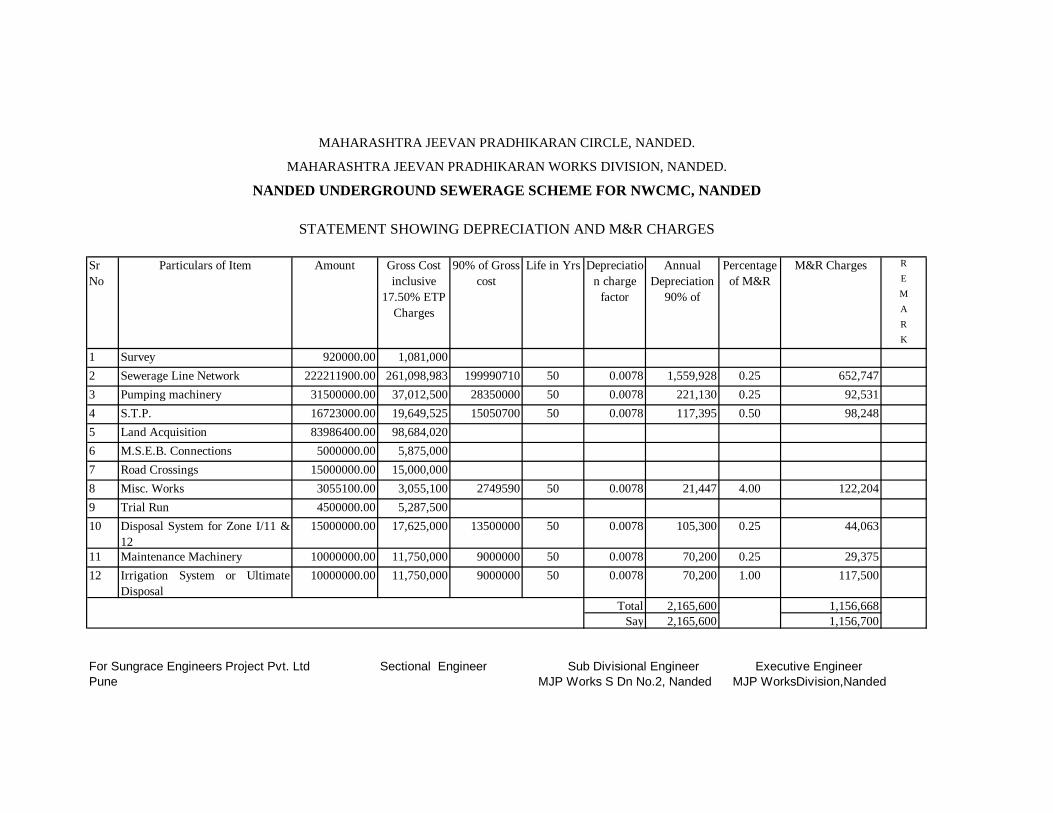
REMARK
1 Survey 920000.00 1,081,0002 Sewerage Line Network 222211900.00 261,098,983 199990710 50 0.0078 1,559,928 0.25 652,7473 Pumping machinery 31500000.00 37,012,500 28350000 50 0.0078 221,130 0.25 92,5314 S.T.P. 16723000.00 19,649,525 15050700 50 0.0078 117,395 0.50 98,2485 Land Acquisition 83986400.00 98,684,0206 M.S.E.B. Connections 5000000.00 5,875,0007 Road Crossings 15000000.00 15,000,0008 Misc. Works 3055100.00 3,055,100 2749590 50 0.0078 21,447 4.00 122,2049 Trial Run 4500000.00 5,287,50010 Disposal System for Zone I/11 &
1215000000.00 17,625,000 13500000 50 0.0078 105,300 0.25 44,063
11 Maintenance Machinery 10000000.00 11,750,000 9000000 50 0.0078 70,200 0.25 29,37512 Irrigation System or Ultimate
Disposal10000000.00 11,750,000 9000000 50 0.0078 70,200 1.00 117,500
Total 2,165,600 1,156,668Say 2,165,600 1,156,700
For Sungrace Engineers Project Pvt. Ltd Sectional Engineer Sub Divisional Engineer Executive EngineerPune MJP Works S Dn No.2, Nanded MJP WorksDivision,Nanded
MAHARASHTRA JEEVAN PRADHIKARAN CIRCLE, NANDED.
NANDED UNDERGROUND SEWERAGE SCHEME FOR NWCMC, NANDEDMAHARASHTRA JEEVAN PRADHIKARAN WORKS DIVISION, NANDED.
STATEMENT SHOWING DEPRECIATION AND M&R CHARGES
Percentage of M&R
M&R Charges90% of Gross cost
Life in Yrs Depreciation charge
factor
Annual Depreciation
90% of
Sr No
Particulars of Item Amount Gross Cost inclusive
17.50% ETP Charges
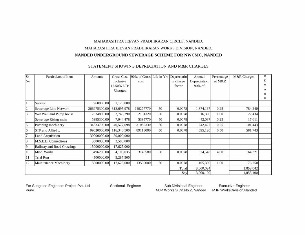
REMARK
1 Survey 960000.00 1,128,0002 Sewerage Line Network 266975300.00 313,695,978 240277770 50 0.0078 1,874,167 0.25 784,2403 Wet Well and Pump house 2334800.00 2,743,390 2101320 50 0.0078 16,390 1.00 27,4344 Sewerage Rising main 5995300.00 7,044,478 5395770 50 0.0078 42,087 0.25 17,6115 Pumping machinery 34533700.00 40,577,098 31080330 50 0.0078 242,427 0.25 101,4436 STP and Allied .. 99020000.00 116,348,500 89118000 50 0.0078 695,120 0.50 581,7437 Land Acquisition 30000000.00 30,000,0008 M.S.E.B. Connections 3500000.00 3,500,0009 Railway and Road Crossings 15000000.00 17,625,00010 Misc. Works 3496200.00 4,108,035 3146580 50 0.0078 24,543 4.00 164,32111 Trial Run 4500000.00 5,287,50012 Maintenance Machinery 15000000.00 17,625,000 13500000 50 0.0078 105,300 1.00 176,250
Total 3,000,034 1,853,042Say 3,000,100 1,853,100
For Sungrace Engineers Project Pvt. Ltd Sectional Engineer Sub Divisional Engineer Executive EngineerPune MJP Works S Dn No.2, Nanded MJP WorksDivision,Nanded
MAHARASHTRA JEEVAN PRADHIKARAN CIRCLE, NANDED.
NANDED UNDERGROUND SEWERAGE SCHEME FOR NWCMC, NANDEDMAHARASHTRA JEEVAN PRADHIKARAN WORKS DIVISION, NANDED.
STATEMENT SHOWING DEPRECIATION AND M&R CHARGES
Percentage of M&R
M&R Charges90% of Gross cost
Life in Yrs Depreciation charge
factor
Annual Depreciation
90% of
Sr No
Particulars of Item Amount Gross Cost inclusive
17.50% ETP Charges

REMARK
1 Survey 480000.00 564,0002 Sewerage Line Network 139526600.00 163,943,755 125573940 50 0.0078 979,477 0.25 409,8593 Wet Well and Pump house 71260500.00 83,731,088 64134450 50 0.0078 500,249 1.00 837,3114 Sewerage Rising main 4054200.00 4,763,685 3648780 50 0.0078 28,460 0.25 11,9095 Pumping machinery 69782700.00 81,994,673 62804430 50 0.0078 489,875 0.25 204,9876 STP and Allied .. 60373300.00 70,938,628 54335970 50 0.0078 423,821 0.50 354,6937 Land Acquisition 18000000.00 18,000,0008 M.S.E.B. Connections 5000000.00 5,000,0009 Road Crossings 5000000.00 5,875,00010 Misc. Works 3055100.00 3,589,743 2749590 50 0.0078 21,447 4.00 143,59011 Trial Run 4500000.00 5,287,50012 Maintenance Machinery 10000000.00 11,750,000 9000000 50 0.0078 70,200 1.00 117,500
Total 2,513,528 2,079,849Say 2,513,600 2,079,900
For Sungrace Engineers Project Pvt. Ltd Sectional Engineer Sub Divisional Engineer Executive EngineerPune MJP Works S Dn No.2, Nanded MJP WorksDivision,Nanded
Life in Yrs Depreciation charge
factor
Annual Depreciation
90% of
Sr No
Particulars of Item Amount Gross Cost inclusive
17.50% ETP Charges
MAHARASHTRA JEEVAN PRADHIKARAN CIRCLE, NANDED.
NANDED UNDERGROUND SEWERAGE SCHEME FOR NWCMC, NANDEDMAHARASHTRA JEEVAN PRADHIKARAN WORKS DIVISION, NANDED.
STATEMENT SHOWING DEPRECIATION AND M&R CHARGES
Percentage of M&R
M&R Charges90% of Gross cost
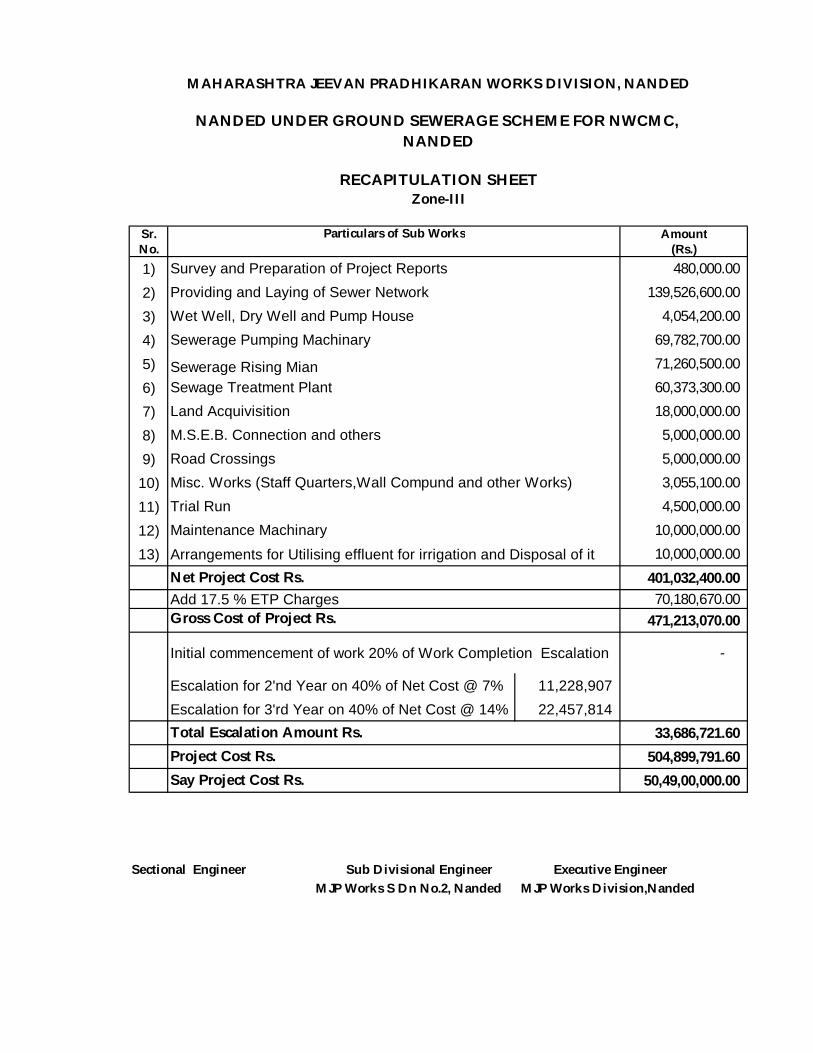
Sr. AmountNo. (Rs.)1) 480,000.00 2) 139,526,600.00 3) 4,054,200.00 4) 69,782,700.00 5) Sewerage Rising Mian 71,260,500.00 6) 60,373,300.00 7) 18,000,000.00 8) 5,000,000.00 9) 5,000,000.00
10) 3,055,100.00 11) 4,500,000.00 12) 10,000,000.00 13) Arrangements for Utilising effluent for irrigation and Disposal of it 10,000,000.00
401,032,400.00 70,180,670.00
471,213,070.00
Initial commencement of work 20% of Work Completion Escalation -
Escalation for 2'nd Year on 40% of Net Cost @ 7% 11,228,907 Escalation for 3'rd Year on 40% of Net Cost @ 14% 22,457,814
33,686,721.60 504,899,791.60
50,49,00,000.00
Sectional Engineer Sub Divisional Engineer Executive Engineer MJP Works S Dn No.2, Nanded MJP Works Division,Nanded
Total Escalation Amount Rs.
Net Project Cost Rs.
Project Cost Rs. Say Project Cost Rs.
Add 17.5 % ETP Charges Gross Cost of Project Rs.
Maintenance Machinary
Misc. Works (Staff Quarters,Wall Compund and other Works)Trial Run
Wet Well, Dry Well and Pump HouseSewerage Pumping Machinary
Land AcquivisitionSewage Treatment Plant
Road CrossingsM.S.E.B. Connection and others
Particulars of Sub Works
Survey and Preparation of Project ReportsProviding and Laying of Sewer Network
MAHARASHTRA JEEVAN PRADHIKARAN WORKS DIVISION, NANDED
NANDED UNDER GROUND SEWERAGE SCHEME FOR NWCMC, NANDED
RECAPITULATION SHEETZone-III

MAHARASHTRA JEEVAN PRADHIKARAN CIRCLE, NANDED
MAHARASHTRA JEEVAN PRADHIKARAN WORKS
DIVISION, NANDED
NANDED UNDERGROUND SEWERAGE SCHEME FOR NWCMC NANDED
ABSTRACT
SUBESTIMATE NO. 1 :- SURVEY, PLANNING, DESIGNING AND PREPARATION OF PLANS AND ESTIMATES.
Qty. Item Rate (Rs.)
Unit Amount (Rs.)
Item No. 1
60 km
Survey, Planning, Designing, Preparation of Plans, Estimates and Detailed Project Report of the Underground Sewerage Scheme for Kamptee City. Inclusive of working Survey, Testing of Samples and necessary activities for Preparation of DPR. Inclusive of Conducting Leveling at the time of execution. Etc. 60 km Survey and Design of All Components of Sewerage System.
8000.00
km 4,80,000.00
Total Rs. 4,80,000.00
(Rs. Four Lacs Eighty Thousand Only) For Sungrace Engineering Projects Pvt. Ltd., Pune (Consulting Engineer)
Sectional Engineer Sub Divisional Engineer, MJP Works Sub Dn, No. 2,
Nanded
Executive Engineer MJP Works Dn., Nanded
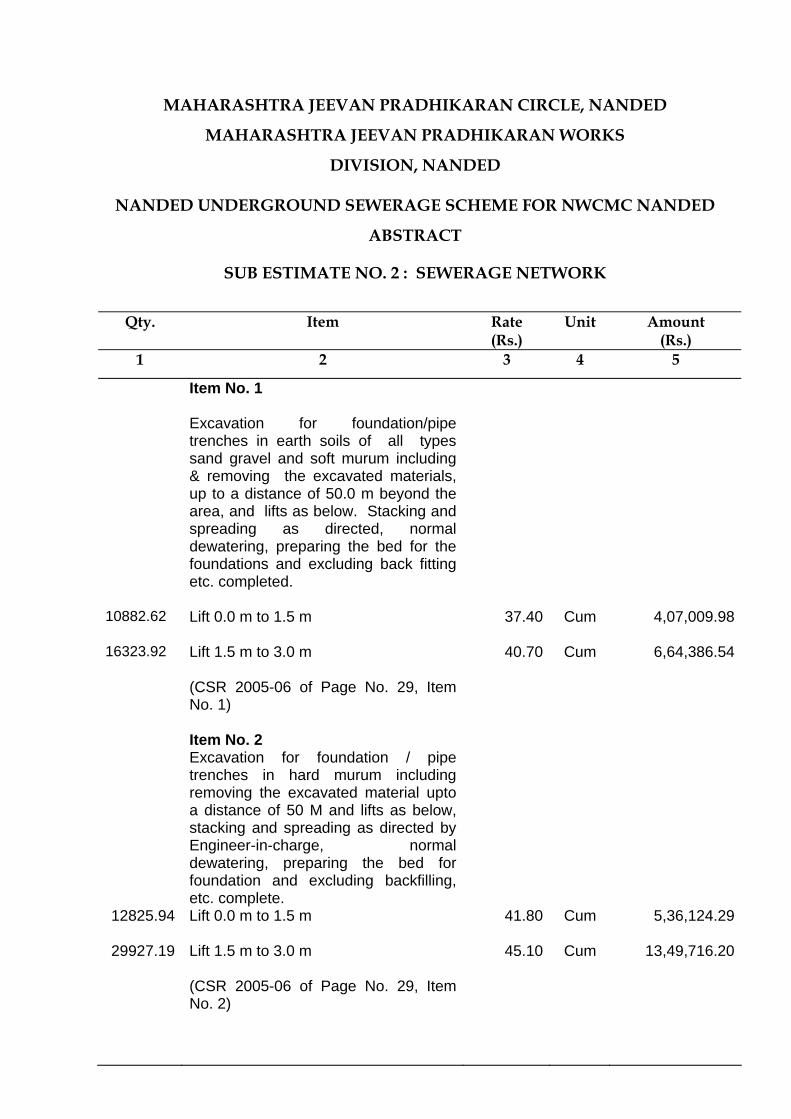
MAHARASHTRA JEEVAN PRADHIKARAN CIRCLE, NANDED
MAHARASHTRA JEEVAN PRADHIKARAN WORKS
DIVISION, NANDED
NANDED UNDERGROUND SEWERAGE SCHEME FOR NWCMC NANDED
ABSTRACT
SUB ESTIMATE NO. 2 : SEWERAGE NETWORK
Qty. Item Rate
(Rs.) Unit Amount
(Rs.) 1 2 3 4 5
Item No. 1
Excavation for foundation/pipe trenches in earth soils of all types sand gravel and soft murum including & removing the excavated materials, up to a distance of 50.0 m beyond the area, and lifts as below. Stacking and spreading as directed, normal dewatering, preparing the bed for the foundations and excluding back fitting etc. completed.
10882.62 Lift 0.0 m to 1.5 m
37.40 Cum 4,07,009.98
16323.92 Lift 1.5 m to 3.0 m
40.70 Cum 6,64,386.54
(CSR 2005-06 of Page No. 29, Item No. 1)
Item No. 2 Excavation for foundation / pipe
trenches in hard murum including removing the excavated material upto a distance of 50 M and lifts as below, stacking and spreading as directed by Engineer-in-charge, normal dewatering, preparing the bed for foundation and excluding backfilling, etc. complete.
12825.94 Lift 0.0 m to 1.5 m
41.80 Cum 5,36,124.29
29927.19 Lift 1.5 m to 3.0 m
45.10 Cum 13,49,716.20
(CSR 2005-06 of Page No. 29, Item No. 2)
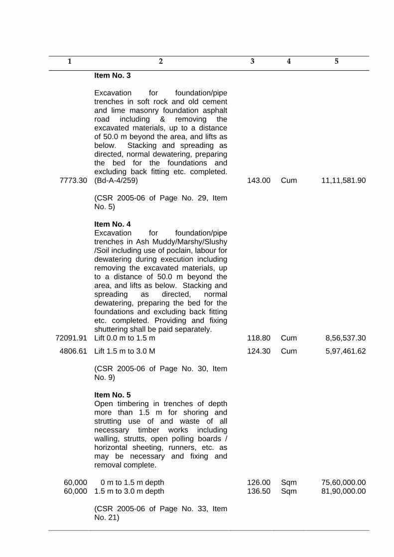
1 2 3 4 5
Item No. 3
7773.30
Excavation for foundation/pipe trenches in soft rock and old cement and lime masonry foundation asphalt road including & removing the excavated materials, up to a distance of 50.0 m beyond the area, and lifts as below. Stacking and spreading as directed, normal dewatering, preparing the bed for the foundations and excluding back fitting etc. completed. (Bd-A-4/259)
143.00
Cum 11,11,581.90
(CSR 2005-06 of Page No. 29, Item No. 5)
Item No. 4
Excavation for foundation/pipe trenches in Ash Muddy/Marshy/Slushy /Soil including use of poclain, labour for dewatering during execution including removing the excavated materials, up to a distance of 50.0 m beyond the area, and lifts as below. Stacking and spreading as directed, normal dewatering, preparing the bed for the foundations and excluding back fitting etc. completed. Providing and fixing shuttering shall be paid separately.
72091.91 Lift 0.0 m to 1.5 m 118.80 Cum 8,56,537.30
4806.61 Lift 1.5 m to 3.0 M 124.30
Cum 5,97,461.62
(CSR 2005-06 of Page No. 30, Item No. 9)
Item No. 5
60,000
Open timbering in trenches of depth more than 1.5 m for shoring and strutting use of and waste of all necessary timber works including walling, strutts, open polling boards / horizontal sheeting, runners, etc. as may be necessary and fixing and removal complete. 0 m to 1.5 m depth 126.00
Sqm 75,60,000.0060,000
1.5 m to 3.0 m depth (CSR 2005-06 of Page No. 33, Item No. 21)
136.50 Sqm
81,90,000.00

1 2 3 4 5
Item No. 6 Providing ISI standard R.C.C. pipes in
standard lengths of following class and diameter suitable for either collar joins or rubber ring joints, including all taxes (Central and local), inspection charges, transport to departmental stores/site, unloading and stacking etc. complete.
Notes : One collar should be supplied with each full length plain ended RCC pipe, cost including in rates below.
Class NP – III
28287 150 mm 168.00 RM 47,52,216.00
2230 200 mm 241.00 RM 5,37,430.00
1375 250 mm 310.00 RM 4,26,250.00
5835 300 mm 325.00 RM 18,96,375.00
3015 350 mm 633.00 RM 19,08,495.00
1635 400 mm 816.00 RM 13,34,160.00
710 450 mm 896.00 RM 6,36,160.00
1490 500 mm 989.00 RM 14,73,610.00
2630 600 mm 1288.00 RM 33,87,440.00
2080 700 mm 1510.00 RM 31,40,800.00
370 800 mm 1852.00 RM 6,85,240.00
120 1000 mm 2230.00 RM 2,67,600.00
295 1100 mm 2909.00 RM 8,58,155.00
(CSR 2005-06 of Page No. 80- 84 Item No.1e)
Item No. 7
Lowering, laying and jointing in proper grade and alignment R.C.C. pipes with collar joints in C.M. 1:1 proportion or socketed R.C.C. pipes with rubber joints (excluding cost of conveyance from stores to site of work, cost of jointing material, labour, giving hydraulic testing etc. completes as directed by Engineer-in-charge (For all class of pipes.).
28287 150 mm 24.15 RM 6,83,131.05
2230 200 mm 35.70 RM 79,611.00
1375 250 mm 44.10 RM 60,637.50

1 2 3 4 5
5835 300 mm 53.55 RM 3,12,464.25
3015 350 mm 63.00 RM 1,89,945.00
1635 400 mm 70.35 RM 1,15,022.25
710 450 mm 79.80 RM 56,658.00
1490 500 mm 89.25 RM 1,32,982.50
2630 600 mm 107.10 RM 2,81,673.00
2080 700 mm 133.35 RM 2,77,368.00
370 800 mm 141.75 RM 52,447.00
120 1000 mm 221.55 RM 26,586.00
295 1100 mm 270.90 RM 79,915.50
(CSR 2005-06 of Page No. 84, Item No. 2)
Item No. 8 77398.97 Refilling the trenches with available
excavated material with soft material first over pipeline and then hard material in 15 cm layer with all leads and lifts including consolidation, surcharging etc. complete 16.80
Cum 13,00,302.60 (CSR 2005-06 of Page No. 33, Item
No. 16)
Item No. 9
250000
Dewatering the excavated trenches and pools of water in the building trenches / pipeline trenches, well works by using pumps and other devices including disposing off water to safe distance as directed by engineer -in-charge (including cost of machinery, labour, fuel), etc. complete. 15.75
BHP Hr
39,75,500.00
(CSR 2005-06 of Page No. 32, Item No. 15)
Item No. 10 Providing and laying in citu cement
concrete M-15/ 1:2:4 of trap / granite / quartzite metal for foundation and bedding including form work, dewatering, compacting roughening them if special finish is to be provided finishing if required and curing etc. complete.
5670.63 For Bedding 1712.55 Cum 97,11,237.4018032.05 For Road Reinstating 1712.55 Cum 3,08,80,787.00
(CSR 2005-06 of Page No. 12, Sr No. 30)
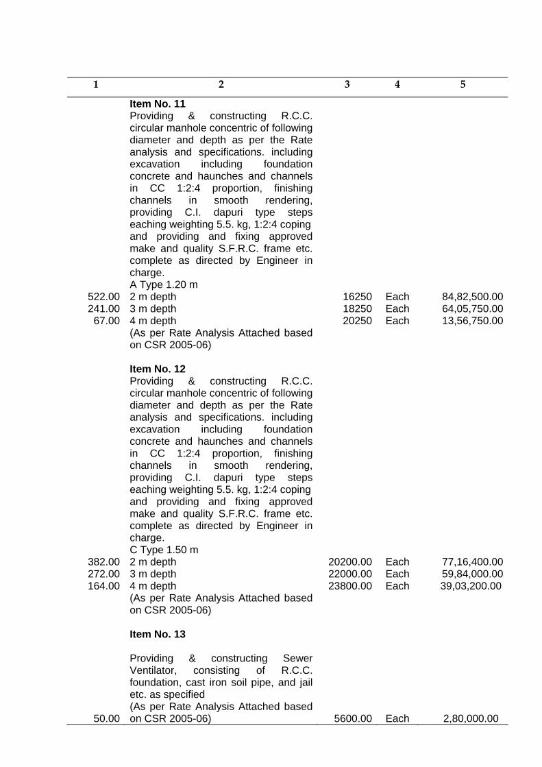
1 2 3 4 5
Item No. 11 Providing & constructing R.C.C.
circular manhole concentric of following diameter and depth as per the Rate analysis and specifications. including excavation including foundation concrete and haunches and channels in CC 1:2:4 proportion, finishing channels in smooth rendering, providing C.I. dapuri type steps eaching weighting 5.5. kg, 1:2:4 coping
522.00 241.00 67.00
and providing and fixing approved make and quality S.F.R.C. frame etc. complete as directed by Engineer in charge. A Type 1.20 m 2 m depth 3 m depth 4 m depth
162501825020250
Each Each Each
84,82,500.0064,05,750.0013,56,750.00
(As per Rate Analysis Attached based on CSR 2005-06)
Item No. 12 Providing & constructing R.C.C.
circular manhole concentric of following diameter and depth as per the Rate analysis and specifications. including excavation including foundation concrete and haunches and channels in CC 1:2:4 proportion, finishing channels in smooth rendering, providing C.I. dapuri type steps eaching weighting 5.5. kg, 1:2:4 coping
382.00 272.00 164.00
and providing and fixing approved make and quality S.F.R.C. frame etc. complete as directed by Engineer in charge. C Type 1.50 m 2 m depth 3 m depth 4 m depth
20200.0022000.0023800.00
Each Each Each
77,16,400.00 59,84,000.00 39,03,200.00
(As per Rate Analysis Attached based on CSR 2005-06)
Item No. 13 Providing & constructing Sewer
Ventilator, consisting of R.C.C. foundation, cast iron soil pipe, and jail etc. as specified
50.00
(As per Rate Analysis Attached based on CSR 2005-06) 5600.00
Each 2,80,000.00
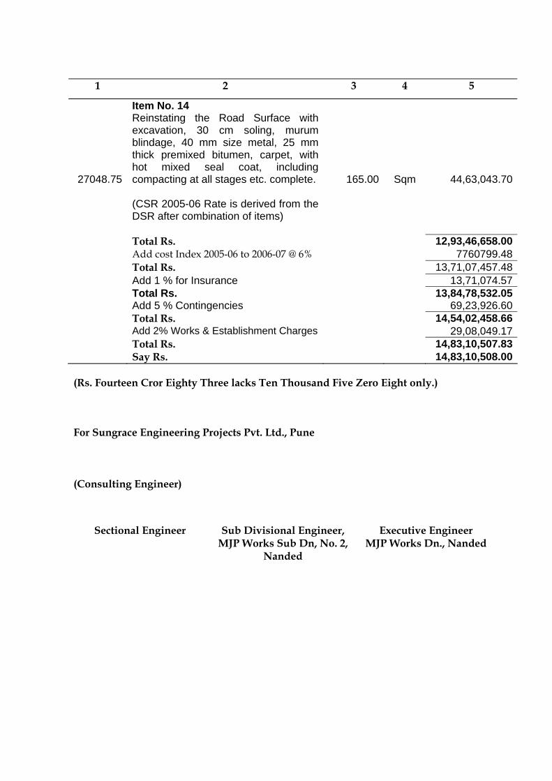
1 2 3 4 5
Item No. 14
27048.75
Reinstating the Road Surface with excavation, 30 cm soling, murum blindage, 40 mm size metal, 25 mm thick premixed bitumen, carpet, with hot mixed seal coat, including compacting at all stages etc. complete.
165.00
Sqm 44,63,043.70
(CSR 2005-06 Rate is derived from the DSR after combination of items)
Total Rs. 12,93,46,658.00 Add cost Index 2005-06 to 2006-07 @ 6% 7760799.48 Total Rs. 13,71,07,457.48 Add 1 % for Insurance 13,71,074.57 Total Rs. 13,84,78,532.05 Add 5 % Contingencies 69,23,926.60 Total Rs. 14,54,02,458.66 Add 2% Works & Establishment Charges 29,08,049.17 Total Rs. 14,83,10,507.83 Say Rs. 14,83,10,508.00
(Rs. Fourteen Cror Eighty Three lacks Ten Thousand Five Zero Eight only.)
For Sungrace Engineering Projects Pvt. Ltd., Pune (Consulting Engineer)
Sectional Engineer Sub Divisional Engineer, MJP Works Sub Dn, No. 2,
Nanded
Executive Engineer MJP Works Dn., Nanded
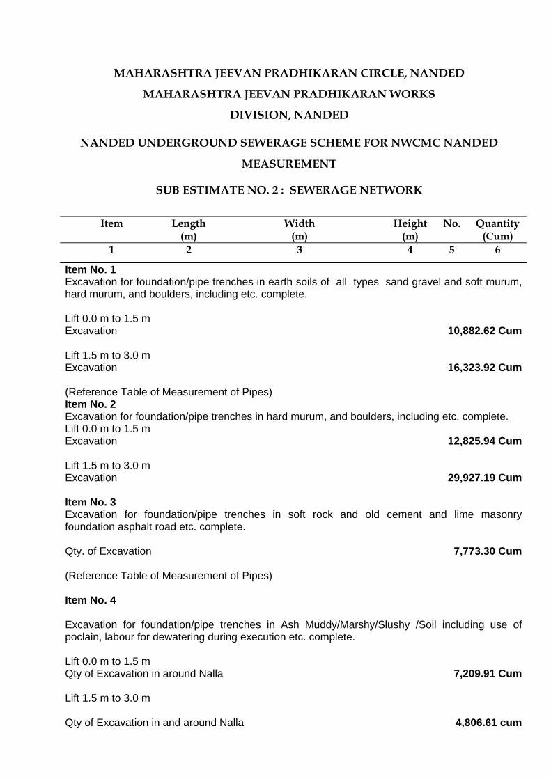
MAHARASHTRA JEEVAN PRADHIKARAN CIRCLE, NANDED
MAHARASHTRA JEEVAN PRADHIKARAN WORKS
DIVISION, NANDED
NANDED UNDERGROUND SEWERAGE SCHEME FOR NWCMC NANDED
MEASUREMENT
SUB ESTIMATE NO. 2 : SEWERAGE NETWORK
Item Length
(m) Width
(m) Height
(m) No. Quantity
(Cum) 1 2 3 4 5 6
Item No. 1 Excavation for foundation/pipe trenches in earth soils of all types sand gravel and soft murum, hard murum, and boulders, including etc. complete. Lift 0.0 m to 1.5 m Excavation 10,882.62 Cum Lift 1.5 m to 3.0 m Excavation
16,323.92 Cum
(Reference Table of Measurement of Pipes) Item No. 2 Excavation for foundation/pipe trenches in hard murum, and boulders, including etc. complete. Lift 0.0 m to 1.5 m Excavation 12,825.94 Cum Lift 1.5 m to 3.0 m Excavation
29,927.19 Cum
Item No. 3 Excavation for foundation/pipe trenches in soft rock and old cement and lime masonry foundation asphalt road etc. complete. Qty. of Excavation
7,773.30 Cum
(Reference Table of Measurement of Pipes)
Item No. 4
Excavation for foundation/pipe trenches in Ash Muddy/Marshy/Slushy /Soil including use of poclain, labour for dewatering during execution etc. complete. Lift 0.0 m to 1.5 m Qty of Excavation in around Nalla
7,209.91 Cum
Lift 1.5 m to 3.0 m
Qty of Excavation in and around Nalla 4,806.61 cum
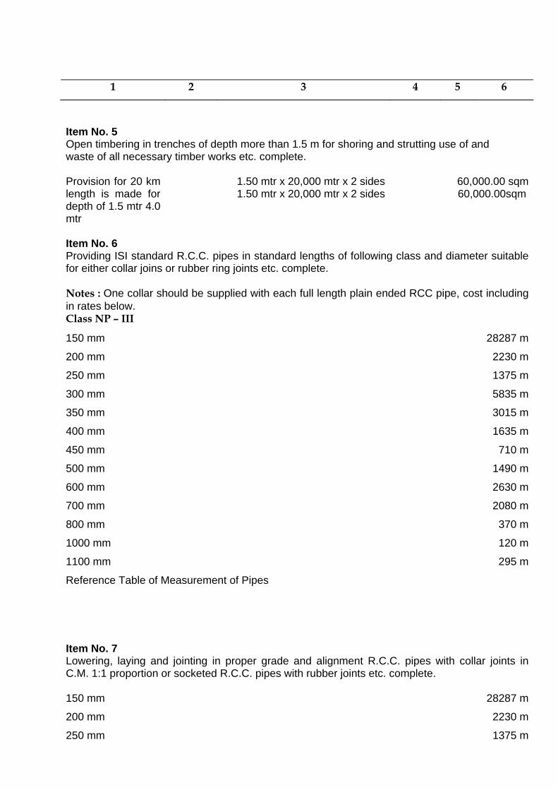
1 2 3 4 5 6
Item No. 5 Open timbering in trenches of depth more than 1.5 m for shoring and strutting use of and waste of all necessary timber works etc. complete.
Provision for 20 km length is made for depth of 1.5 mtr 4.0 mtr
1.50 mtr x 20,000 mtr x 2 sides1.50 mtr x 20,000 mtr x 2 sides
60,000.00 sqm 60,000.00sqm
Item No. 6 Providing ISI standard R.C.C. pipes in standard lengths of following class and diameter suitable for either collar joins or rubber ring joints etc. complete. Notes : One collar should be supplied with each full length plain ended RCC pipe, cost including in rates below. Class NP – III
150 mm 28287 m
200 mm 2230 m
250 mm 1375 m
300 mm 5835 m
350 mm 3015 m
400 mm 1635 m
450 mm 710 m
500 mm 1490 m
600 mm 2630 m
700 mm 2080 m
800 mm 370 m
1000 mm 120 m
1100 mm 295 m
Reference Table of Measurement of Pipes
Item No. 7
Lowering, laying and jointing in proper grade and alignment R.C.C. pipes with collar joints in C.M. 1:1 proportion or socketed R.C.C. pipes with rubber joints etc. complete. 150 mm 28287 m
200 mm 2230 m
250 mm 1375 m
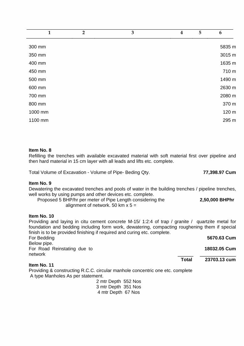
1 2 3 4 5 6
300 mm 5835 m
350 mm 3015 m
400 mm 1635 m
450 mm 710 m
500 mm 1490 m
600 mm 2630 m
700 mm 2080 m
800 mm 370 m
1000 mm 120 m
1100 mm 295 m
Item No. 8 Refilling the trenches with available excavated material with soft material first over pipeline and then hard material in 15 cm layer with all leads and lifts etc. complete. Total Volume of Excavation - Volume of Pipe- Beding Qty.
77,398.97 Cum
Item No. 9 Dewatering the excavated trenches and pools of water in the building trenches / pipeline trenches, well works by using pumps and other devices etc. complete.
Proposed 5 BHP/hr per meter of Pipe Length considering the alignment of network. 50 km x 5 =
2,50,000 BHPhr
Item No. 10
Providing and laying in citu cement concrete M-15/ 1:2:4 of trap / granite / quartzite metal for foundation and bedding including form work, dewatering, compacting roughening them if special finish is to be provided finishing if required and curing etc. complete. For Bedding Below pipe.
5670.63 Cum
For Road Reinstating due to network
Total
18032.05 Cum 23703.13 cum
Item No. 11 Providing & constructing R.C.C. circular manhole concentric one etc. complete A type Manholes As per statement.
2 mtr Depth 552 Nos 3 mtr Depth 351 Nos 4 mtr Depth 67 Nos
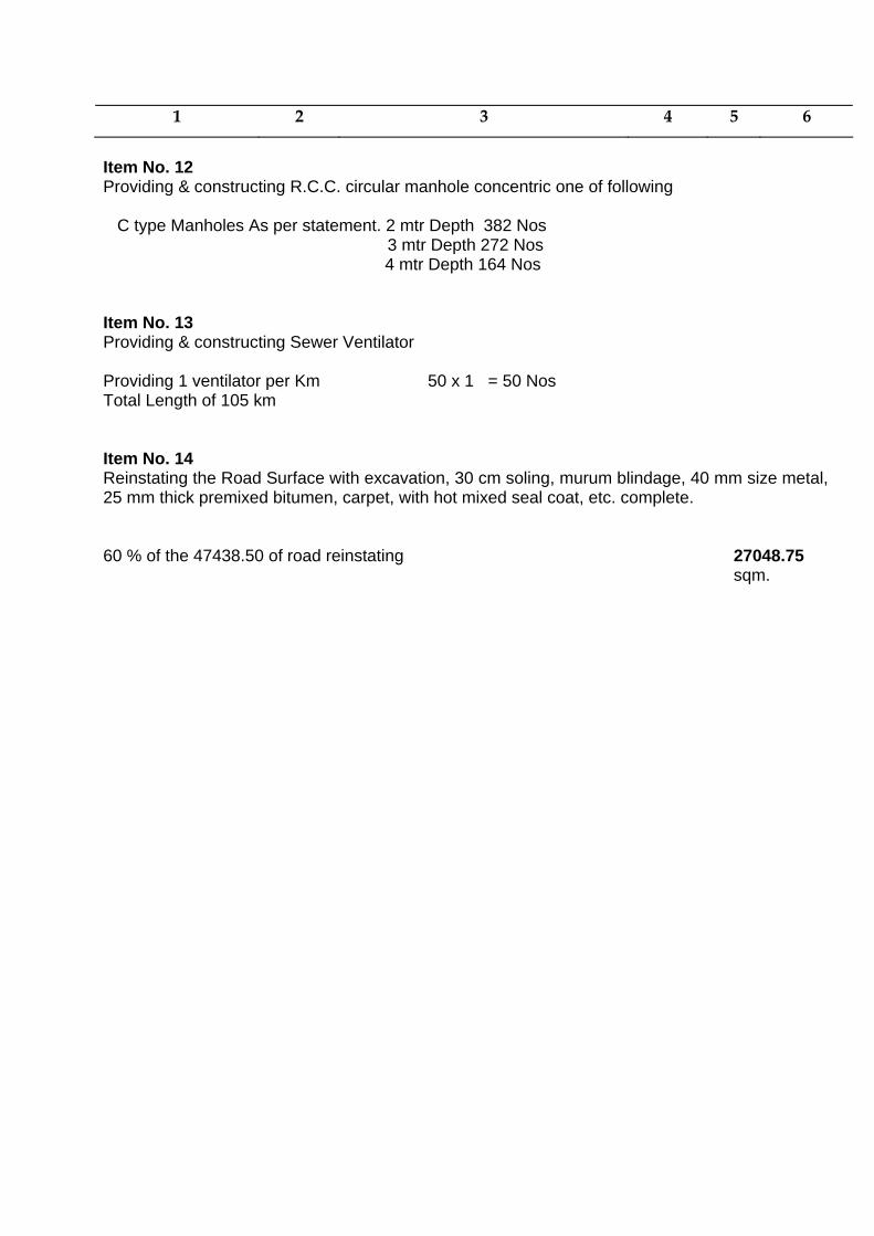
1 2 3 4 5 6
Item No. 12 Providing & constructing R.C.C. circular manhole concentric one of following
C type Manholes As per statement. 2 mtr Depth 382 Nos
3 mtr Depth 272 Nos 4 mtr Depth 164 Nos
Item No. 13 Providing & constructing Sewer Ventilator Providing 1 ventilator per Km 50 x 1 = 50 Nos Total Length of 105 km Item No. 14 Reinstating the Road Surface with excavation, 30 cm soling, murum blindage, 40 mm size metal, 25 mm thick premixed bitumen, carpet, with hot mixed seal coat, etc. complete.
60 % of the 47438.50 of road reinstating 27048.75 sqm.

MAHARASHTRA JEEVAN PRADHIKARAN CIRCLE, NANDED
MAHARASHTRA JEEVAN PRADHIKARAN WORKS
DIVISION, NANDED
NANDED UNDERGROUND SEWERAGE SCHEME FOR NWCMC NANDED
ABSTRACT
SUB ESTIMATE NO. 3 : WET WELL AND DRY WELL PUMPHOUSE
Qty. Item Rate
(Rs.) Unit Amount
(Rs.) 1 2 3 4 5
Item No. 1
Excavation in general in soft material comprising of soft soil, soft murum. Sand, hard murum, with boulders in wet or dry condition for Head Works i.e. Intake Well, Connecting pipe, Jack Well, Pump House, Supply Well, etc. for lift 0 to 1.5 M and lead of 150 M including barricading, guarding, disposing off surplus excavated stuff within a radius of 0.5 km. as directed by Engineer-in-charge, etc. Complete excluding refilling.
896.535 Lift 0.0 m to 1.5 m 52.50 Cum 47,068.09
755.535 Lift 1.5 m to 3.0 m 59.85 Cum 45,218.77
626.535 Lift 3.0 m to 4.5 m 67.20 Cum 42,103.15
509.535 Lift 4.5 m to 6.0 m 74.55 Cum 37,985.83
215.752 Lift 6.0 m to 7.5 m 81.90 Cum 17,670.09
(CSR 2005-06 of Page No. 39, Item No.11 (b))
Item No. 2
Excavation in general in hard material comprising of soft rock, hard rock, Manjara rock, etc, by blasting. Chiseling as required in wet or dry condition for Head Works i.e. Intake
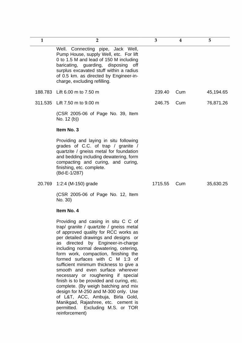
1 2 3 4 5
Well. Connecting pipe, Jack Well, Pump House, supply Well, etc. For lift 0 to 1.5 M and lead of 150 M including baricating, guarding, disposing off surplus excavated stuff within a radius of 0.5 km. as directed by Engineer-in-charge, excluding refilling.
188.783 Lift 6.00 m to 7.50 m
239.40 Cum 45,194.65
311.535 Lift 7.50 m to 9.00 m
246.75 Cum 76,871.26
(CSR 2005-06 of Page No. 39, Item No. 12 (b))
Item No. 3
Providing and laying in situ following grades of C.C. of trap / granite / quartzite / gneiss metal for foundation and bedding including dewatering, form compacting and curing, and curing, finishing, etc. complete. (Bd-E-1/287)
20.769 1:2:4 (M-150) grade
1715.55 Cum 35,630.25
(CSR 2005-06 of Page No. 12, Item No. 30)
Item No. 4
Providing and casing in situ C C of trap/ granite / quartzite / gneiss metal of approved quality for RCC works as per detailed drawings and designs or as directed by Engineer-in-charge including normal dewatering, cetering, form work, compaction, finishing the formed surfaces with C M 1:3 of sufficient minimum thickness to give a smooth and even surface wherever necessary or roughening if special finish is to be provided and curing, etc. complete. (By weigh batching and mix design for M-250 and M-300 only. Use of L&T, ACC, Ambuja, Birla Gold, Manikgad, Rajashree, etc. cement is permitted. Excluding M.S. or TOR reinforcement)
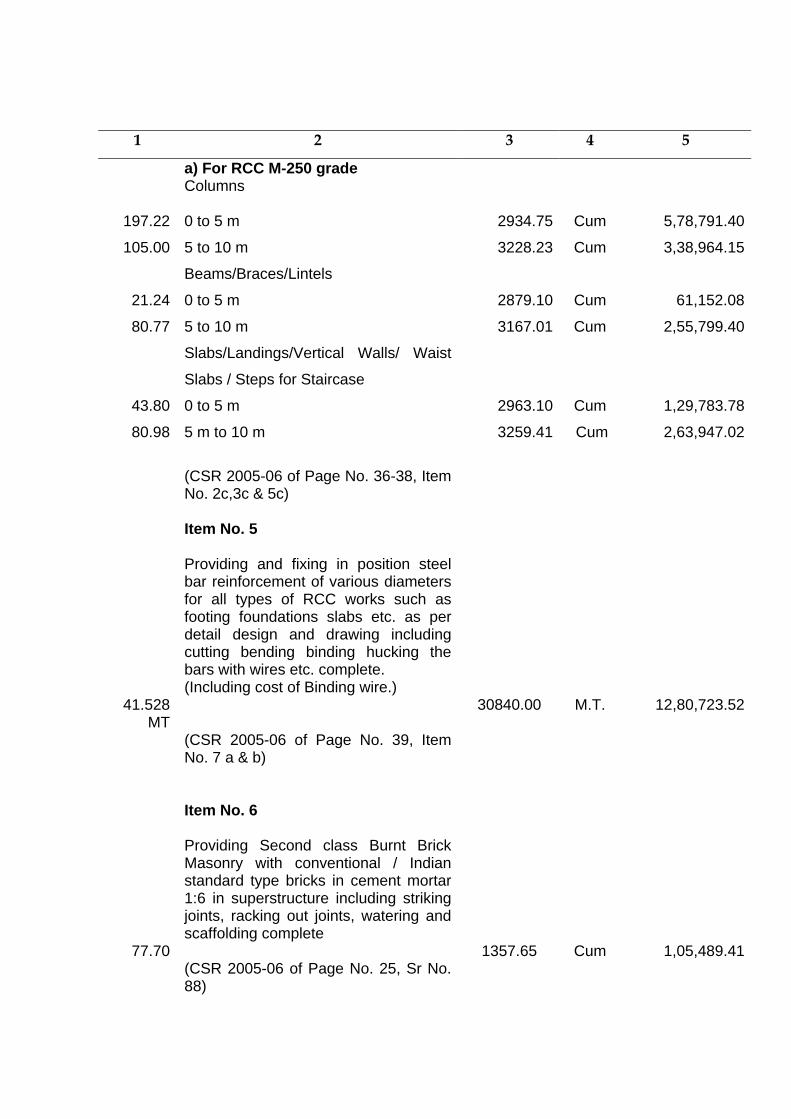
1 2 3 4 5
a) For RCC M-250 grade Columns
197.22 0 to 5 m 2934.75 Cum 5,78,791.40
105.00 5 to 10 m 3228.23 Cum 3,38,964.15
21.24
Beams/Braces/Lintels
0 to 5 m 2879.10 Cum 61,152.08
80.77 5 to 10 m 3167.01 Cum 2,55,799.40
43.80
Slabs/Landings/Vertical Walls/ Waist
Slabs / Steps for Staircase
0 to 5 m 2963.10
Cum 1,29,783.78
80.98 5 m to 10 m 3259.41 Cum 2,63,947.02
(CSR 2005-06 of Page No. 36-38, Item
No. 2c,3c & 5c)
Item No. 5
Providing and fixing in position steel bar reinforcement of various diameters for all types of RCC works such as footing foundations slabs etc. as per detail design and drawing including cutting bending binding hucking the bars with wires etc. complete. (Including cost of Binding wire.)
41.528 MT
30840.00 M.T. 12,80,723.52
(CSR 2005-06 of Page No. 39, Item No. 7 a & b)
Item No. 6
Providing Second class Burnt Brick Masonry with conventional / Indian standard type bricks in cement mortar 1:6 in superstructure including striking joints, racking out joints, watering and scaffolding complete
77.70 (CSR 2005-06 of Page No. 25, Sr No. 88)
1357.65 Cum 1,05,489.41
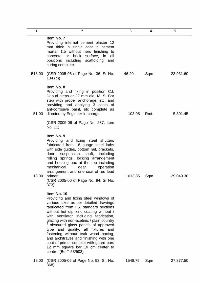
1 2 3 4 5
Item No. 7 Providing internal cement plaster 12
mm thick in single coat in cement mortar 1:5 without neru finishing to concrete or brick surface, in all positions including scaffolding and curing complete.
518.00 (CSR 2005-06 of Page No. 36, Sr No. 134 (b))
46.20 Sqm 23,931.60
Item No. 8
51.00
Providing and fixing in position C.I. Dapuri steps or 22 mm dia. M. S. Bar step with proper anchorage, etc. and providing and applying 3 coats of ant-corrosive paint, etc complete as directed by Engineer-in-charge.
103.95
Rmt.
5,301.45
(CSR 2005-06 of Page No. 237, Item No. 11)
Item No. 9
18.00
Providing and fixing steel shutters fabricated from 18 guage steel laths with side guides, bottom rail, brackets, door, suspension shaft, including rolling springs, locking arrangement and housing box at the top including mechanical gear operation arrangement and one coat of red lead primer. 1613.85
Sqm 29,049.30 (CSR 2005-06 of Page No. 94, Sr No.
373)
Item No. 10
Providing and fixing steel windows of various sizes as per detailed drawings fabricated from I.S. standard sections without hot dip zinc coating without / with ventilator including fabrication, glazing with non-acetinic / plain country / obscured glass panels of approved type and quality, all fixtures and fastening without teak wood boxing, and architraves and finishing with one coat of primer complet with guard bars 12 mm square bar 10 cm center to centre. (Bd-T-53/503)
18.00 (CSR 2005-06 of Page No. 93, Sr. No. 368)
1548.75 Sqm 27,877.50
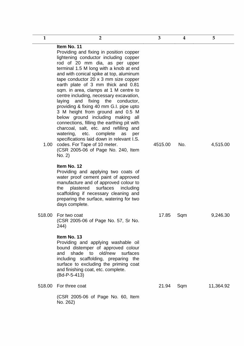
1 2 3 4 5
Item No. 11
1.00
Providing and fixing in position copper lightening conductor including copper rod of 20 mm dia, as per upper terminal 1.5 M long with a knob at end and with conical spike at top, aluminum tape conductor 20 x 3 mm size copper earth plate of 3 mm thick and 0.81 sqm. in area, clamps at 1 M centre to centre including, necessary excavation, laying and fixing the conductor, providing & fixing 40 mm G.I. pipe upto 3 M height from ground and 0.5 M below ground including making all connections, filling the earthing pit with charcoal, salt, etc. and refilling and watering, etc. complete as per specifications laid down in relevant I.S. codes. For Tape of 10 meter. 4515.00
No. 4,515.00 (CSR 2005-06 of Page No. 240, Item
No. 2)
Item No. 12 Providing and applying two coats of
water proof cement paint of approved manufacture and of approved colour to the plastered surfaces including scaffolding if necessary cleaning and preparing the surface, watering for two days complete.
518.00 For two coat 17.85 Sqm 9,246.30 (CSR 2005-06 of Page No. 57, Sr No.
244)
Item No. 13 Providing and applying washable oil
bound distemper of approved colour and shade to old/new surfaces including scaffolding, preparing the surface to excluding the priming coat and finishing coat, etc. complete. (Bd-P-5-413)
518.00 For three coat
21.94 Sqm 11,364.92
(CSR 2005-06 of Page No. 60, Item No. 262)
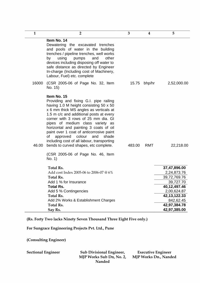
1 2 3 4 5
Item No. 14 Dewatering the excavated trenches
and pools of water in the building trenches / pipeline trenches, well works by using pumps and other devices including disposing off water to
safe distance as directed by Engineer In-charge (Including cost of Machinery, Labour, Fuel) etc. complete
16000 (CSR 2005-06 of Page No. 32, Item
No. 15)
15.75 bhp/hr 2,52,000.00
Item No. 15
46.00
Providing and fixing G.I. pipe railing having 1.0 M height consisting 50 x 50 x 6 mm thick MS angles as verticals at 1.5 m c/c and additional posts at every corner with 3 rows of 25 mm dia. GI pipes of medium class variety as horizontal and painting 3 coats of oil paint over 1 coat of anticorrosive paint of approved colour and shade including cost of all labour, transporting bends to curved shapes, etc complete.
483.00
RMT 22,218.00
(CSR 2005-06 of Page No. 46, Item No. 1)
Total Rs. 37,47,896.00 Add cost Index 2005-06 to 2006-07 @ 6% 2,24,873.76 Total Rs. 39,72,769.76 Add 1 % for Insurance 39,727.70 Total Rs. 40,12,497.46 Add 5 % Contingencies 2,00,624.87 Total Rs. 42,13,122.33 Add 2% Works & Establishment Charges 842,62.45 Total Rs. 42,97,384.78 Say Rs. 42,97,385.00
(Rs. Forty Two lacks Ninety Seven Thousand Three Eight Five only.) For Sungrace Engineering Projects Pvt. Ltd., Pune
(Consulting Engineer) Sectional Engineer Sub Divisional Engineer,
MJP Works Sub Dn, No. 2, Nanded
Executive Engineer MJP Works Dn., Nanded
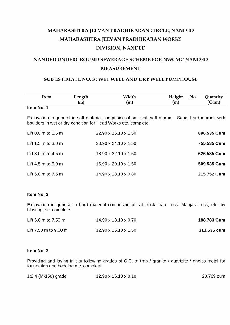
MAHARASHTRA JEEVAN PRADHIKARAN CIRCLE, NANDED
MAHARASHTRA JEEVAN PRADHIKARAN WORKS
DIVISION, NANDED
NANDED UNDERGROUND SEWERAGE SCHEME FOR NWCMC NANDED
MEASUREMENT
SUB ESTIMATE NO. 3 : WET WELL AND DRY WELL PUMPHOUSE
Item Length (m)
Width (m)
Height (m)
No. Quantity (Cum)
Item No. 1
Excavation in general in soft material comprising of soft soil, soft murum. Sand, hard murum, with boulders in wet or dry condition for Head Works etc. complete. Lift 0.0 m to 1.5 m
22.90 x 26.10 x 1.50 896.535 Cum
Lift 1.5 m to 3.0 m 20.90 x 24.10 x 1.50 755.535 Cum
Lift 3.0 m to 4.5 m 18.90 x 22.10 x 1.50 626.535 Cum Lift 4.5 m to 6.0 m
16.90 x 20.10 x 1.50
509.535 Cum
Lift 6.0 m to 7.5 m
14.90 x 18.10 x 0.80
215.752 Cum
Item No. 2
Excavation in general in hard material comprising of soft rock, hard rock, Manjara rock, etc, by blasting etc. complete. Lift 6.0 m to 7.50 m 14.90 x 18.10 x 0.70
188.783 Cum
Lift 7.50 m to 9.00 m 12.90 x 16.10 x 1.50
311.535 cum
Item No. 3
Providing and laying in situ following grades of C.C. of trap / granite / quartzite / gneiss metal for foundation and bedding etc. complete. 1:2:4 (M-150) grade
12.90 x 16.10 x 0.10 20.769 cum
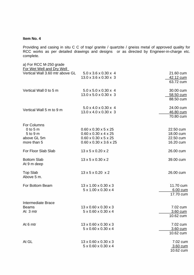
Item No. 4
Providing and casing in situ C C of trap/ granite / quartzite / gneiss metal of approved quality for RCC works as per detailed drawings and designs or as directed by Engineer-in-charge etc. complete. a) For RCC M-250 grade For Wet Well and Dry Well
Vertical Wall 3.60 mtr above GL
5.0 x 3.6 x 0.30 x 4 13.0 x 3.6 x 0.30 x 3
21.60 cum 42.12 cum 63.72 cum
Vertical Wall 0 to 5 m 5.0 x 5.0 x 0.30 x 4 13.0 x 5.0 x 0.30 x 3
30.00 cum 58.50 cum 88.50 cum
Vertical Wall 5 m to 9 m
5.0 x 4.0 x 0.30 x 4 13.0 x 4.0 x 0.30 x 3
24.00 cum 46.80 cum 70.80 cum
For Columns 0 to 5 m 5 to 9 m above GL 5m more than 5 For Floor Slab Slab Bottom Slab At 9 m deep Top Slab Above 5 m.
0.60 x 0.30 x 5 x 25 0.60 x 0.30 x 4 x 25 0.60 x 0.30 x 5 x 25 0.60 x 0.30 x 3.6 x 25 13 x 5 x 0.20 x 2 13 x 5 x 0.30 x 2 13 x 5 x 0.20 x 2
22.50 cum 18.00 cum 22.50 cum 16.20 cum 26.00 cum 39.00 cum 26.00 cum
For Bottom Beam Intermediate Brace Beams At 3 mtr At 6 mtr At GL
13 x 1.00 x 0.30 x 3 5 x 1.00 x 0.30 x 4 13 x 0.60 x 0.30 x 3 5 x 0.60 x 0.30 x 4 13 x 0.60 x 0.30 x 3 5 x 0.60 x 0.30 x 4 13 x 0.60 x 0.30 x 3 5 x 0.60 x 0.30 x 4
11.70 cum 6.00 cum 17.70 cum 7.02 cum 3.60 cum 10.62 cum 7.02 cum 3.60 cum 10.62 cum
7.02 cum
3.60 cum 10.62 cum
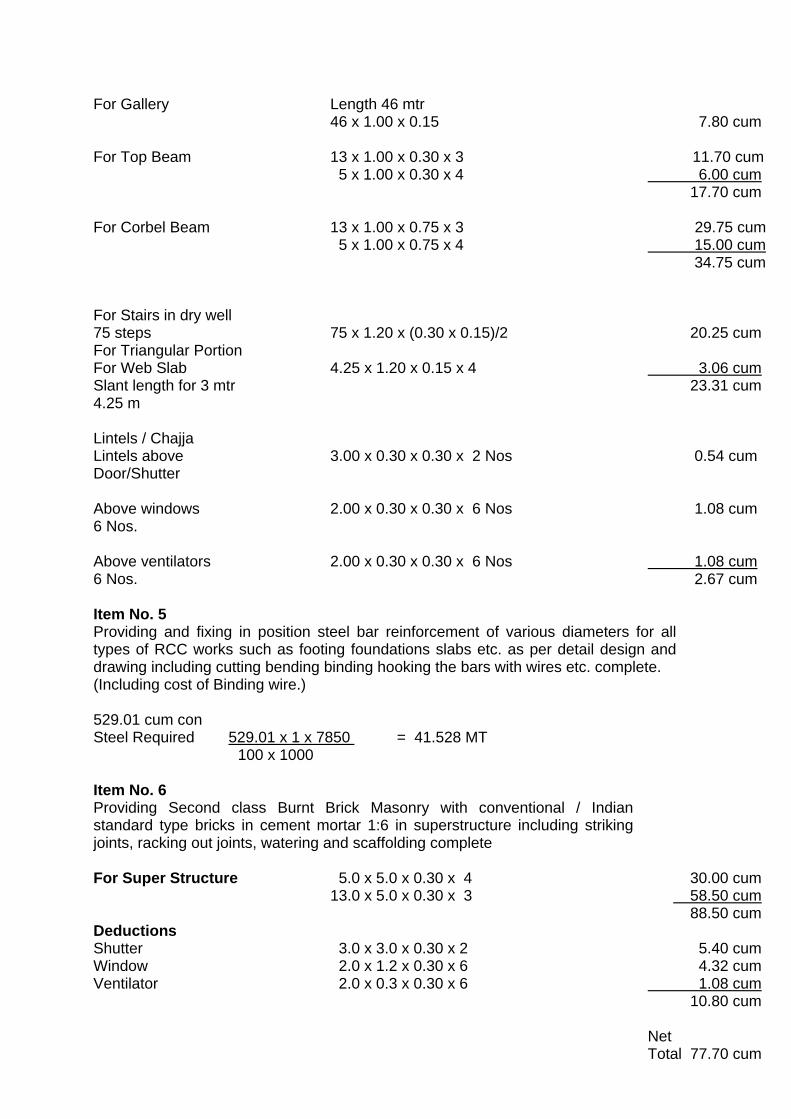
For Gallery
Length 46 mtr 46 x 1.00 x 0.15
7.80 cum
For Top Beam
13 x 1.00 x 0.30 x 3 5 x 1.00 x 0.30 x 4
11.70 cum 6.00 cum 17.70 cum
For Corbel Beam For Stairs in dry well 75 steps For Triangular Portion For Web Slab Slant length for 3 mtr 4.25 m Lintels / Chajja Lintels above Door/Shutter
Above windows 6 Nos. Above ventilators 6 Nos.
13 x 1.00 x 0.75 x 3 5 x 1.00 x 0.75 x 4 75 x 1.20 x (0.30 x 0.15)/2 4.25 x 1.20 x 0.15 x 4 3.00 x 0.30 x 0.30 x 2 Nos 2.00 x 0.30 x 0.30 x 6 Nos 2.00 x 0.30 x 0.30 x 6 Nos
29.75 cum 15.00 cum 34.75 cum 20.25 cum 3.06 cum 23.31 cum 0.54 cum 1.08 cum 1.08 cum 2.67 cum
Item No. 5 Providing and fixing in position steel bar reinforcement of various diameters for all types of RCC works such as footing foundations slabs etc. as per detail design and drawing including cutting bending binding hooking the bars with wires etc. complete. (Including cost of Binding wire.) 529.01 cum con Steel Required 529.01 x 1 x 7850 = 41.528 MT 100 x 1000
Item No. 6 Providing Second class Burnt Brick Masonry with conventional / Indian standard type bricks in cement mortar 1:6 in superstructure including striking joints, racking out joints, watering and scaffolding complete For Super Structure
5.0 x 5.0 x 0.30 x 4 13.0 x 5.0 x 0.30 x 3
30.00 cum 58.50 cum 88.50 cum
Deductions Shutter Window Ventilator
3.0 x 3.0 x 0.30 x 2 2.0 x 1.2 x 0.30 x 6 2.0 x 0.3 x 0.30 x 6
5.40 cum 4.32 cum 1.08 cum 10.80 cum Net Total 77.70 cum
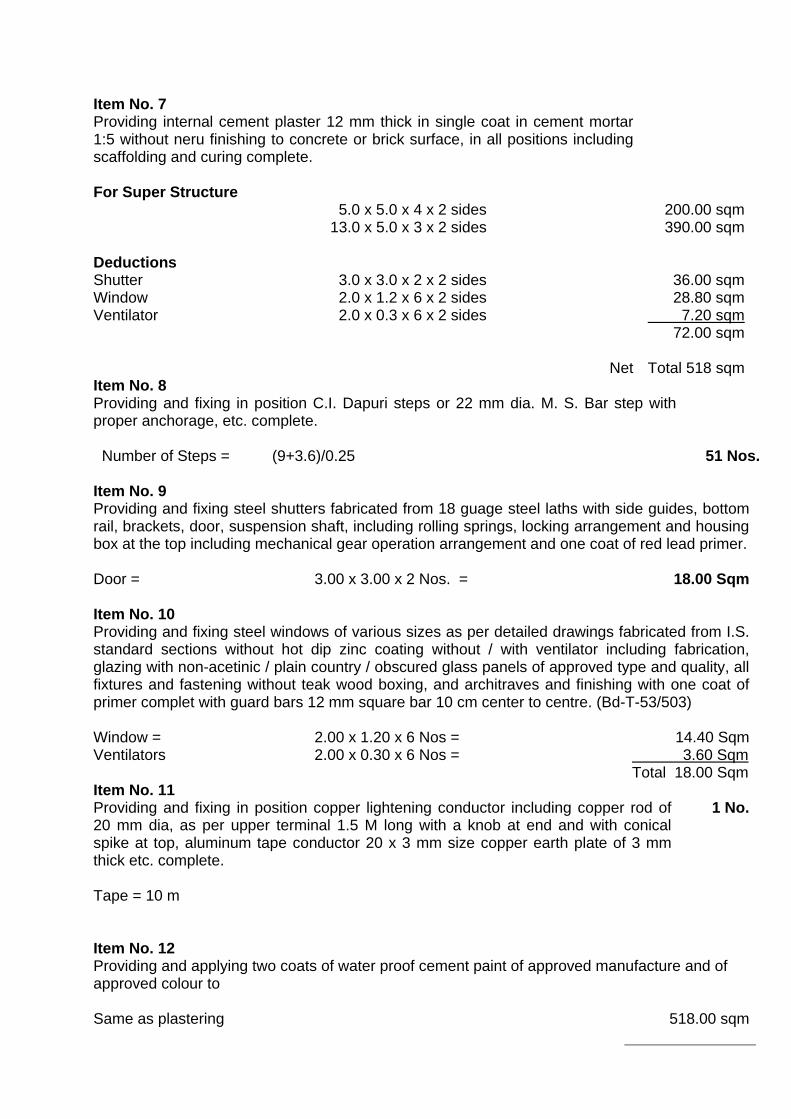
Item No. 7 Providing internal cement plaster 12 mm thick in single coat in cement mortar 1:5 without neru finishing to concrete or brick surface, in all positions including scaffolding and curing complete.
For Super Structure Deductions Shutter Window Ventilator
5.0 x 5.0 x 4 x 2 sides 13.0 x 5.0 x 3 x 2 sides 3.0 x 3.0 x 2 x 2 sides 2.0 x 1.2 x 6 x 2 sides 2.0 x 0.3 x 6 x 2 sides
Net
200.00 sqm 390.00 sqm 36.00 sqm 28.80 sqm 7.20 sqm 72.00 sqm Total 518 sqm
Item No. 8 Providing and fixing in position C.I. Dapuri steps or 22 mm dia. M. S. Bar step with proper anchorage, etc. complete. Number of Steps = (9+3.6)/0.25
51 Nos. Item No. 9 Providing and fixing steel shutters fabricated from 18 guage steel laths with side guides, bottom rail, brackets, door, suspension shaft, including rolling springs, locking arrangement and housing box at the top including mechanical gear operation arrangement and one coat of red lead primer. Door =
3.00 x 3.00 x 2 Nos. = 18.00 Sqm
Item No. 10 Providing and fixing steel windows of various sizes as per detailed drawings fabricated from I.S. standard sections without hot dip zinc coating without / with ventilator including fabrication, glazing with non-acetinic / plain country / obscured glass panels of approved type and quality, all fixtures and fastening without teak wood boxing, and architraves and finishing with one coat of primer complet with guard bars 12 mm square bar 10 cm center to centre. (Bd-T-53/503) Window = Ventilators
2.00 x 1.20 x 6 Nos = 2.00 x 0.30 x 6 Nos =
14.40 Sqm 3.60 SqmTotal 18.00 Sqm
Item No. 11 Providing and fixing in position copper lightening conductor including copper rod of 20 mm dia, as per upper terminal 1.5 M long with a knob at end and with conical spike at top, aluminum tape conductor 20 x 3 mm size copper earth plate of 3 mm thick etc. complete.
1 No.
Tape = 10 m
Item No. 12 Providing and applying two coats of water proof cement paint of approved manufacture and of approved colour to Same as plastering
518.00 sqm
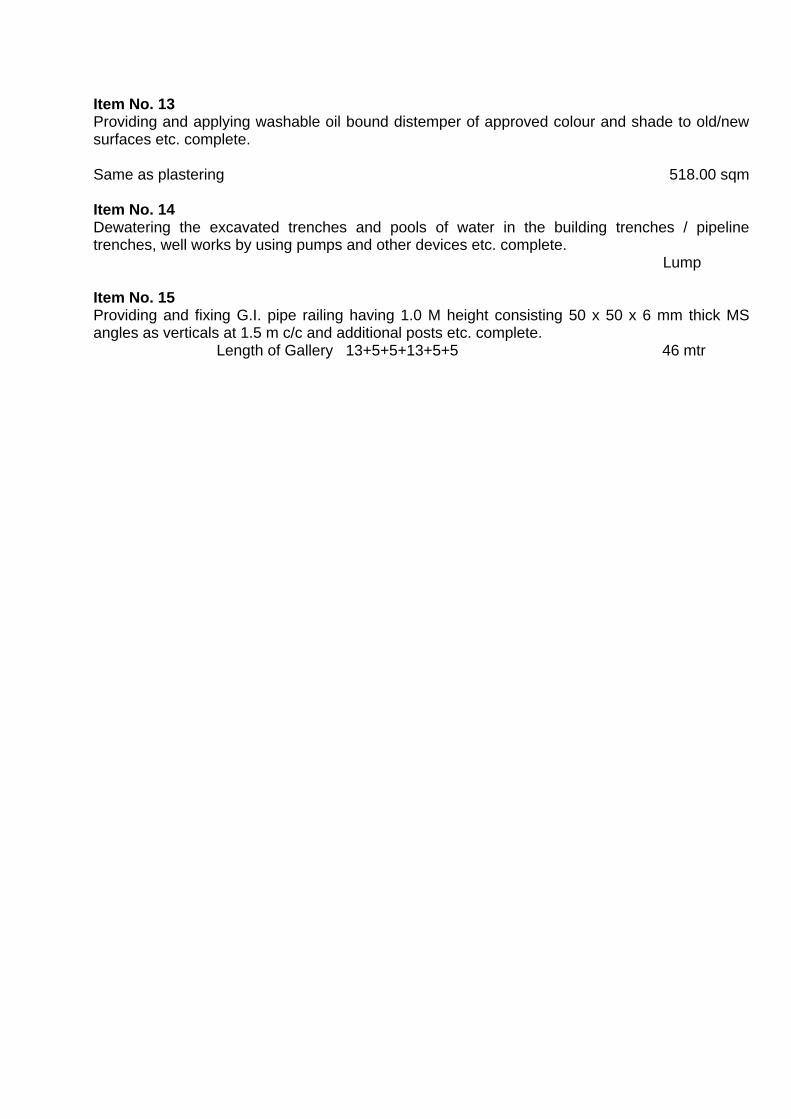
Item No. 13 Providing and applying washable oil bound distemper of approved colour and shade to old/new surfaces etc. complete. Same as plastering
518.00 sqm
Item No. 14 Dewatering the excavated trenches and pools of water in the building trenches / pipeline trenches, well works by using pumps and other devices etc. complete. Lump Item No. 15 Providing and fixing G.I. pipe railing having 1.0 M height consisting 50 x 50 x 6 mm thick MS angles as verticals at 1.5 m c/c and additional posts etc. complete. Length of Gallery 13+5+5+13+5+5 46 mtr
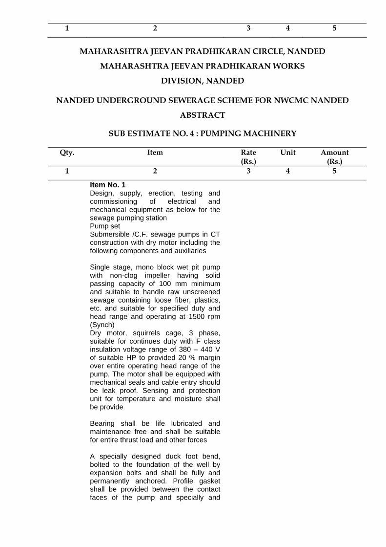
1 2 3 4 5
MAHARASHTRA JEEVAN PRADHIKARAN CIRCLE, NANDED
MAHARASHTRA JEEVAN PRADHIKARAN WORKS
DIVISION, NANDED
NANDED UNDERGROUND SEWERAGE SCHEME FOR NWCMC NANDED
ABSTRACT
SUB ESTIMATE NO. 4 : PUMPING MACHINERY
Qty. Item Rate (Rs.)
Unit Amount (Rs.)
1 2 3 4 5
Item No. 1 Design, supply, erection, testing and commissioning of electrical and mechanical equipment as below for the sewage pumping station
Pump set Submersible /C.F. sewage pumps in CT construction with dry motor including the following components and auxiliaries
Single stage, mono block wet pit pump with non-clog impeller having solid passing capacity of 100 mm minimum and suitable to handle raw unscreened sewage containing loose fiber, plastics, etc. and suitable for specified duty and head range and operating at 1500 rpm (Synch)
Dry motor, squirrels cage, 3 phase, suitable for continues duty with F class insulation voltage range of 380 – 440 V of suitable HP to provided 20 % margin over entire operating head range of the pump. The motor shall be equipped with mechanical seals and cable entry should be leak proof. Sensing and protection unit for temperature and moisture shall be provide
Bearing shall be life lubricated and maintenance free and shall be suitable for entire thrust load and other forces
A specially designed duck foot bend, bolted to the foundation of the well by expansion bolts and shall be fully and permanently anchored. Profile gasket shall be provided between the contact faces of the pump and specially and
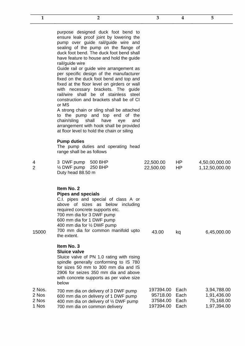
1 2 3 4 5
purpose designed duck foot bend to ensure leak proof joint by lowering the pump over guide rail/guide wire and sealing of the pump on the flange of duck foot bend. The duck foot bend shall have feature to house and hold the guide rail/guide wire
Guide rail or guide wire arrangement as per specific design of the manufacturer fixed on the duck foot bend and top and fixed at the floor level on girders or wall with necessary brackets. The guide rail/wire shall be of stainless steel construction and brackets shall be of CI or MS
A strong chain or sling shall be attached to the pump and top end of the chain/sling shall have eye and arrangement with hook shall be provided at floor level to hold the chain or siling
Pump duties The pump duties and operating head range shall be as follows
4 2
3 DWF pump 500 BHP ½ DWF pump 250 BHP Duty head 88.50 m
22,500.00 22,500.00
HP HP
4,50,00,000.001,12,50,000.00
Item No. 2
Pipes and specials
15000
C.I. pipes and special of class A or above of sizes as below including required concrete supports etc. 700 mm dia for 3 DWF pump 600 mm dia for 1 DWF pump 400 mm dia for ½ DWF pump 700 mm dia for common manifold upto the extent.
43.00
kq 6,45,000.00
Item No. 3 Sluice valve
2 Nos. 2 Nos 2 Nos 1 Nos
Sluice valve of PN 1.0 rating with rising spindle generally conforming to IS 780 for sizes 50 mm to 300 mm dia and IS 2906 for seizes 350 mm dia and above with concrete supports as per valve size below
700 mm dia on delivery of 3 DWF pump 600 mm dia on delivery of 1 DWF pump 400 mm dia on delivery of ½ DWF pump 700 mm dia on common delivery
197394.0095718.0037584.00
197394.00
Each Each Each Each
3,94,788.001,91,436.00 75,168.001,97,394.00

1 2 3 4 5
Item No. 4 Reflux valves
2 2 2
Reflux valve of PN 1.0 rating generally conforming to IS-5312 with renewable gun metal sealing face on swing door with concrete supports as per valve sizes below 700 mm dia on delivery of 3 DWF pump 600 mm dia on delivery of 1 DWF pump 400 mm dia on delivery of ½ DWF pump
244080.00113850.00
36753.00
Each Each Each
4,88,160.002,27,700.00
73,506.00
Item No. 5 Lifting equipment
Job
It will consist of over head traveling crane with 5 tonne capacity chain pulley block, end carriage gantry girder, longitudinal girders and rails traveling trolley etc. complete for pump house of span 13 m.
Lump Sum
Job 2,75,000.00
Item No. 6 L.T. Control Panel and Starter
Cubical control panel, floor mounting housing a bus bar chamber, 5 Nos , compartment for motor control circuits and 1 No. for in corner, indicating monitoring and protection instruments/relays and capacitors as detailed below.
Capacitor (200 KVAR total )
4
Starters shall be with air break contractors incorporating over current relay. No- volt release, current sensing single phase preventor, reverse phasing protection, water level guard/dry run protection and ammeter with selector switch. The starter shall be wired to motor for temperature protection and moisture protection feature. The DOL and Star-delta starters shall be mounted on panel and autotransformer starter shall be floor mounting type and cost of the starter shall be included in the cost of panel. The types of starter shall be as follows. 3 DWF pump 500 BHP 225589.00
Each 4,51,178.00
2 ½ DWF Pump 250 BHP 108551 Each 2,17,102.00
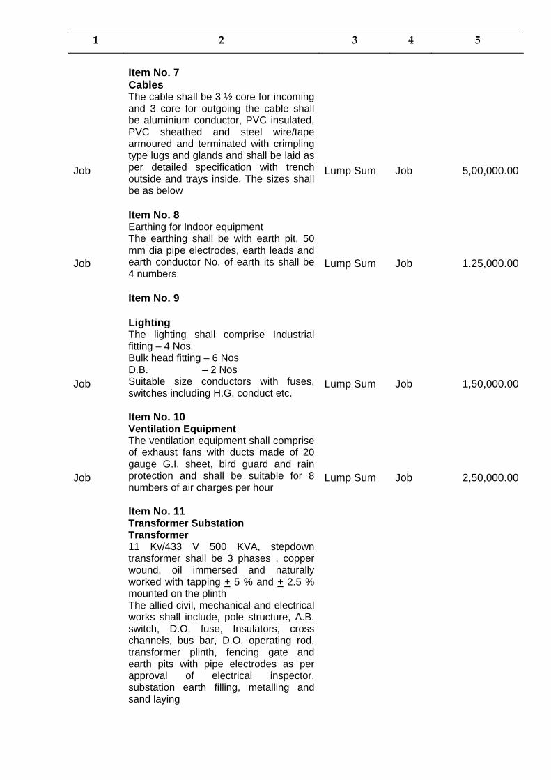
1 2 3 4 5
Item No. 7 Cables
Job
The cable shall be 3 ½ core for incoming and 3 core for outgoing the cable shall be aluminium conductor, PVC insulated, PVC sheathed and steel wire/tape armoured and terminated with crimpling type lugs and glands and shall be laid as per detailed specification with trench outside and trays inside. The sizes shall be as below
Lump Sum
Job
5,00,000.00
Item No. 8 Earthing for Indoor equipment
Job
The earthing shall be with earth pit, 50 mm dia pipe electrodes, earth leads and earth conductor No. of earth its shall be 4 numbers
Lump Sum
Job
1.25,000.00
Item No. 9
Lighting
Job
The lighting shall comprise Industrial fitting – 4 Nos Bulk head fitting – 6 Nos D.B. – 2 Nos Suitable size conductors with fuses, switches including H.G. conduct etc.
Lump Sum
Job
1,50,000.00
Item No. 10 Ventilation Equipment
Job
The ventilation equipment shall comprise of exhaust fans with ducts made of 20 gauge G.I. sheet, bird guard and rain protection and shall be suitable for 8 numbers of air charges per hour
Lump Sum
Job
2,50,000.00
Item No. 11 Transformer Substation
Transformer 11 Kv/433 V 500 KVA, stepdown transformer shall be 3 phases , copper wound, oil immersed and naturally worked with tapping + 5 % and + 2.5 % mounted on the plinth
The allied civil, mechanical and electrical works shall include, pole structure, A.B. switch, D.O. fuse, Insulators, cross channels, bus bar, D.O. operating rod, transformer plinth, fencing gate and earth pits with pipe electrodes as per approval of electrical inspector, substation earth filling, metalling and sand laying
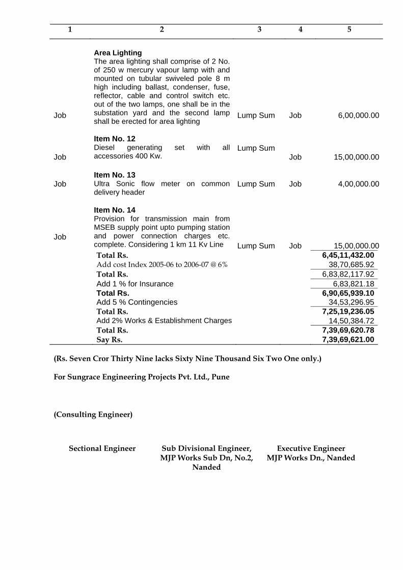
1 2 3 4 5
Area Lighting
Job
The area lighting shall comprise of 2 No. of 250 w mercury vapour lamp with and mounted on tubular swiveled pole 8 m high including ballast, condenser, fuse, reflector, cable and control switch etc. out of the two lamps, one shall be in the substation yard and the second lamp shall be erected for area lighting
Lump Sum
Job
6,00,000.00
Job
Item No. 12 Diesel generating set with all accessories 400 Kw.
Lump Sum
Job
15,00,000.00 Job
Item No. 13 Ultra Sonic flow meter on common delivery header
Lump Sum
Job
4,00,000.00
Job
Item No. 14 Provision for transmission main from MSEB supply point upto pumping station and power connection charges etc. complete. Considering 1 km 11 Kv Line
Lump Sum
Job
15,00,000.00 Total Rs. 6,45,11,432.00 Add cost Index 2005-06 to 2006-07 @ 6% 38,70,685.92 Total Rs. 6,83,82,117.92 Add 1 % for Insurance 6,83,821.18 Total Rs. 6,90,65,939.10 Add 5 % Contingencies 34,53,296.95 Total Rs. 7,25,19,236.05 Add 2% Works & Establishment Charges 14,50,384.72 Total Rs. 7,39,69,620.78 Say Rs. 7,39,69,621.00
(Rs. Seven Cror Thirty Nine lacks Sixty Nine Thousand Six Two One only.) For Sungrace Engineering Projects Pvt. Ltd., Pune (Consulting Engineer)
Sectional Engineer Sub Divisional Engineer, MJP Works Sub Dn, No.2,
Nanded
Executive Engineer MJP Works Dn., Nanded
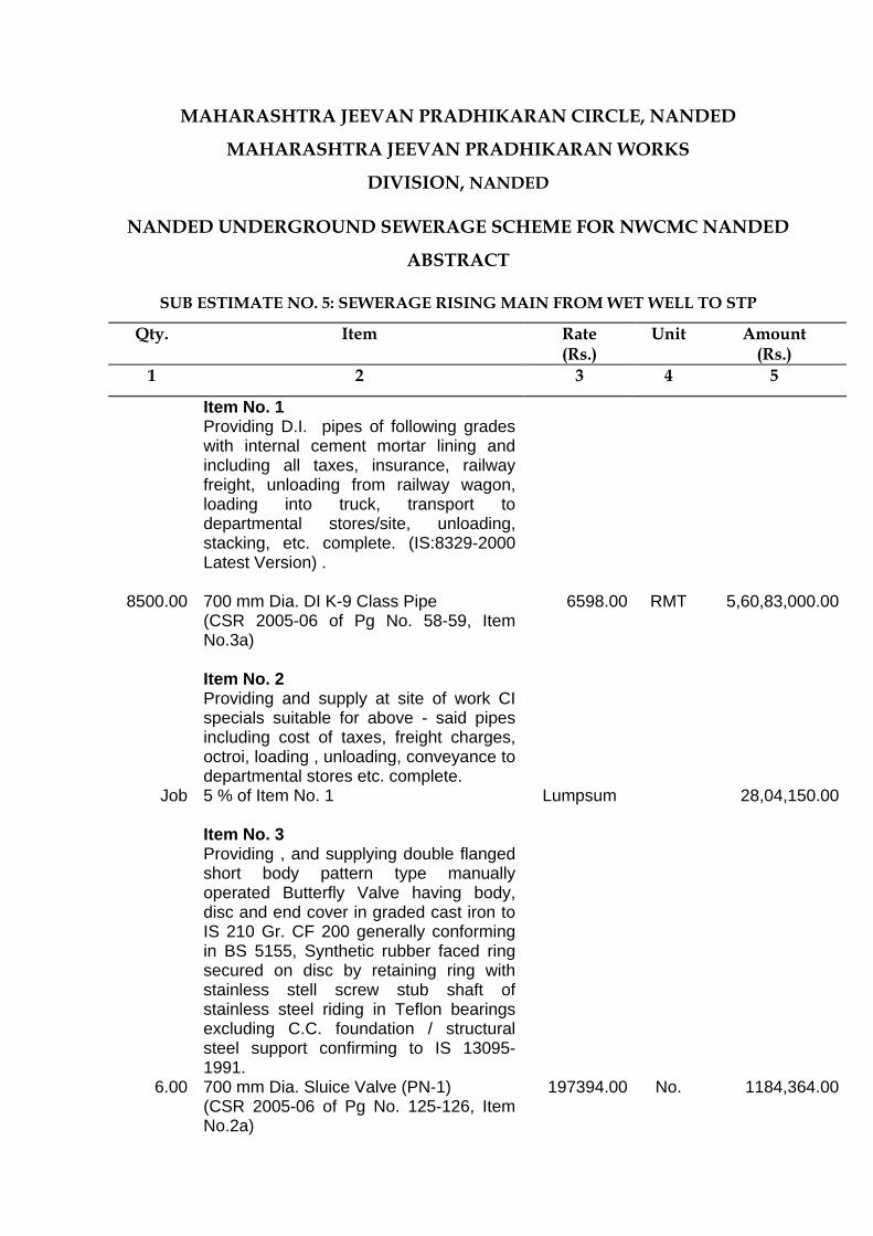
MAHARASHTRA JEEVAN PRADHIKARAN CIRCLE, NANDED
MAHARASHTRA JEEVAN PRADHIKARAN WORKS
DIVISION, NANDED
NANDED UNDERGROUND SEWERAGE SCHEME FOR NWCMC NANDED
ABSTRACT
SUB ESTIMATE NO. 5: SEWERAGE RISING MAIN FROM WET WELL TO STP
Qty. Item Rate (Rs.)
Unit Amount (Rs.)
1 2 3 4 5
Item No. 1 Providing D.I. pipes of following grades
with internal cement mortar lining and including all taxes, insurance, railway freight, unloading from railway wagon, loading into truck, transport to departmental stores/site, unloading, stacking, etc. complete. (IS:8329-2000 Latest Version) .
8500.00 700 mm Dia. DI K-9 Class Pipe 6598.00 RMT 5,60,83,000.00 (CSR 2005-06 of Pg No. 58-59, Item
No.3a)
Item No. 2
Providing and supply at site of work CI specials suitable for above - said pipes including cost of taxes, freight charges, octroi, loading , unloading, conveyance to departmental stores etc. complete.
Job 5 % of Item No. 1
Lumpsum 28,04,150.00
Item No. 3 Providing , and supplying double flanged
short body pattern type manually operated Butterfly Valve having body, disc and end cover in graded cast iron to IS 210 Gr. CF 200 generally conforming in BS 5155, Synthetic rubber faced ring secured on disc by retaining ring with stainless stell screw stub shaft of stainless steel riding in Teflon bearings excluding C.C. foundation / structural steel support confirming to IS 13095-1991.
6.00 700 mm Dia. Sluice Valve (PN-1) (CSR 2005-06 of Pg No. 125-126, Item No.2a)
197394.00 No. 1184,364.00
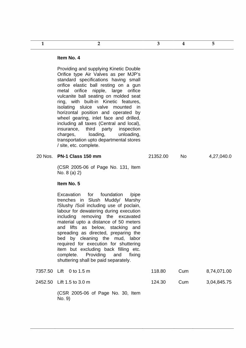
1 2 3 4 5
Item No. 4
Providing and supplying Kinetic Double Orifice type Air Valves as per MJP’s standard specifications having small orifice elastic ball resting on a gun metal orifice nipple, large orifice vulcanite ball seating on molded seat ring, with built-in Kinetic features, isolating sluice valve mounted in horizontal position and operated by wheel gearing, inlet face and drilled, including all taxes (Central and local), insurance, third party inspection charges, loading, unloading, transportation upto departmental stores / site, etc. complete.
20 Nos. PN-1 Class 150 mm
21352.00 No 4,27,040.0
(CSR 2005-06 of Page No. 131, Item No. 8 (a) 2)
Item No. 5
Excavation for foundation /pipe trenches in Slush Muddy/ Marshy /Slushy /Soil including use of poclain, labour for dewatering during execution including removing the excavated material upto a distance of 50 meters and lifts as below, stacking and spreading as directed, preparing the bed by cleaning the mud, labor required for execution for shuttering item but excluding back filling etc. complete. Providing and fixing shuttering shall be paid separately.
7357.50
Lift 0 to 1.5 m
118.80
Cum 8,74,071.00
2452.50
Lift 1.5 to 3.0 m
124.30
Cum 3,04,845.75
(CSR 2005-06 of Page No. 30, Item No. 9)
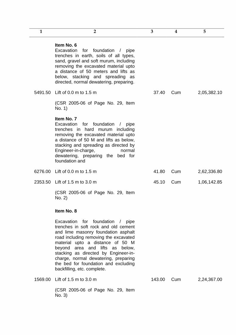
1 2 3 4 5
Item No. 6
Excavation for foundation / pipe trenches in earth, soils of all types, sand, gravel and soft murum, including removing the excavated material upto a distance of 50 meters and lifts as below, stacking and spreading as directed, normal dewatering, preparing.
5491.50 Lift of 0.0 m to 1.5 m
37.40 Cum 2,05,382.10
(CSR 2005-06 of Page No. 29, Item No. 1)
Item No. 7 Excavation for foundation / pipe
trenches in hard murum including removing the excavated material upto a distance of 50 M and lifts as below, stacking and spreading as directed by Engineer-in-charge, normal dewatering, preparing the bed for foundation and
6276.00 Lift of 0.0 m to 1.5 m
41.80 Cum 2,62,336.80
2353.50 Lift of 1.5 m to 3.0 m
45.10 Cum 1,06,142.85
(CSR 2005-06 of Page No. 29, Item No. 2)
Item No. 8
Excavation for foundation / pipe trenches in soft rock and old cement and lime masonry foundation asphalt road including removing the excavated material upto a distance of 50 M beyond area and lifts as below, stacking as directed by Engineer-in-charge, normal dewatering, preparing the bed for foundation and excluding backfilling, etc. complete.
1569.00 Lift of 1.5 m to 3.0 m
143.00 Cum 2,24,367.00
(CSR 2005-06 of Page No. 29, Item No. 3)

1 2 3 4 5
Item No. 9
Lowering, laying and jointing with CI LA/DI class. pipes and specials of following class and diameter including cost of conveyance from stores to site of works including cost of all labour, material, rubber ring, giving satisfactory hydraulic testing as per
8500.00 700 mm Dia. D.I. K-9 Class Pipe 216.30 RMT 18,38,550.0 (CSR 2005-06 of Page No. 56, Item
No. 2-a-13)
Item No. 10 Lowering, laying and jointing in position
following C.I. D/F Reflux valves, Butterfly valves and Sluice valves including cost of all labour jointing material, including nut bolts and giving satisfactory hydraulic testing etc. complete. (Rate for all class of valves)
6.00 700 mm Dia. Sluice Pipe 3822.00 No. 22,932.00 (CSR 2005-06 of Page No. 128, Item
No. 3)
Item No. 11 Lowering, laying and fixing in proper
alignment and position all types of C.I. air valves as directed by Engineer-in-charge including cost of conveyance from stores to site of work, cost of all material and giving satisfactory hydraulic testing, etc. complete. (for all class of valves).
20 Kinetic Air Valve 150 mm 288.75 No 5,775.00 (CSR 2005-06 of Page No. 133, Item
No. 9 c )
Item No. 12 Providing and constructing B.B.
masonry valve chamber with 15 cm thick 1:3:6 proportion PCC bedding, excluding excavation, B.B. masonry in C.M. 1: 5 cm thick pre-cast RCC frame and cover, etc. complete as directed by Engineer-in-charge. (Note : Wall thickness: 0.23 M for depth of 1.2 M and 0.35 M for balance depth exceeding 1. 2 MM)
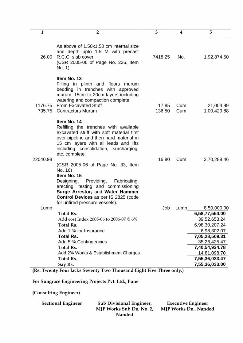
1 2 3 4 5
26.00
As above of 1.50x1.50 cm internal size and depth upto 1.5 M with precast R.C.C. slab cover. 7418.25
No. 1,92,874.50 (CSR 2005-06 of Page No. 226, Item
No. 1)
Item No. 13 Filling in plinth and floors murum
bedding in trenches with approved murum, 15cm to 20cm layers including watering and compaction complete.
1176.75 From Excavated Stuff 17.85 Cum 21,004.99735.75 Contractors Murum 136.50 Cum 1,00,429.88
Item No. 14 Refilling the trenches with available
excavated stuff with soft material first over pipeline and then hard material m 15 cm layers with all leads and lifts including consolidation, surcharging, etc. complete.
22040.98 16.80 Cum 3,70,288.46 (CSR 2005-06 of Page No. 33, Item
No. 16)
Item No. 15 Designing, Providing, Fabricating,
erecting, testing and commissioning Surge Arrestor, and Water Hammer Control Devices as per IS 2825 (code for unfired pressure vessels).
Lump Job Lump 8,50,000.00 Total Rs. 6,58,77,554.00 Add cost Index 2005-06 to 2006-07 @ 6% 39,52,653.24 Total Rs. 6,98,30,207.24 Add 1 % for Insurance 6,98,302.07 Total Rs. 7,05,28,509.31 Add 5 % Contingencies 35,26,425.47 Total Rs. 7,40,54,934.78 Add 2% Works & Establishment Charges 14,81,098.70 Total Rs. 7,55,36,033.47 Say Rs. 7,55,36,033.00
(Rs. Twenty Four lacks Seventy Two Thousand Eight Five Three only.) For Sungrace Engineering Projects Pvt. Ltd., Pune (Consulting Engineer)
Sectional Engineer Sub Divisional Engineer, MJP Works Sub Dn, No. 2,
Nanded
Executive Engineer MJP Works Dn., Nanded
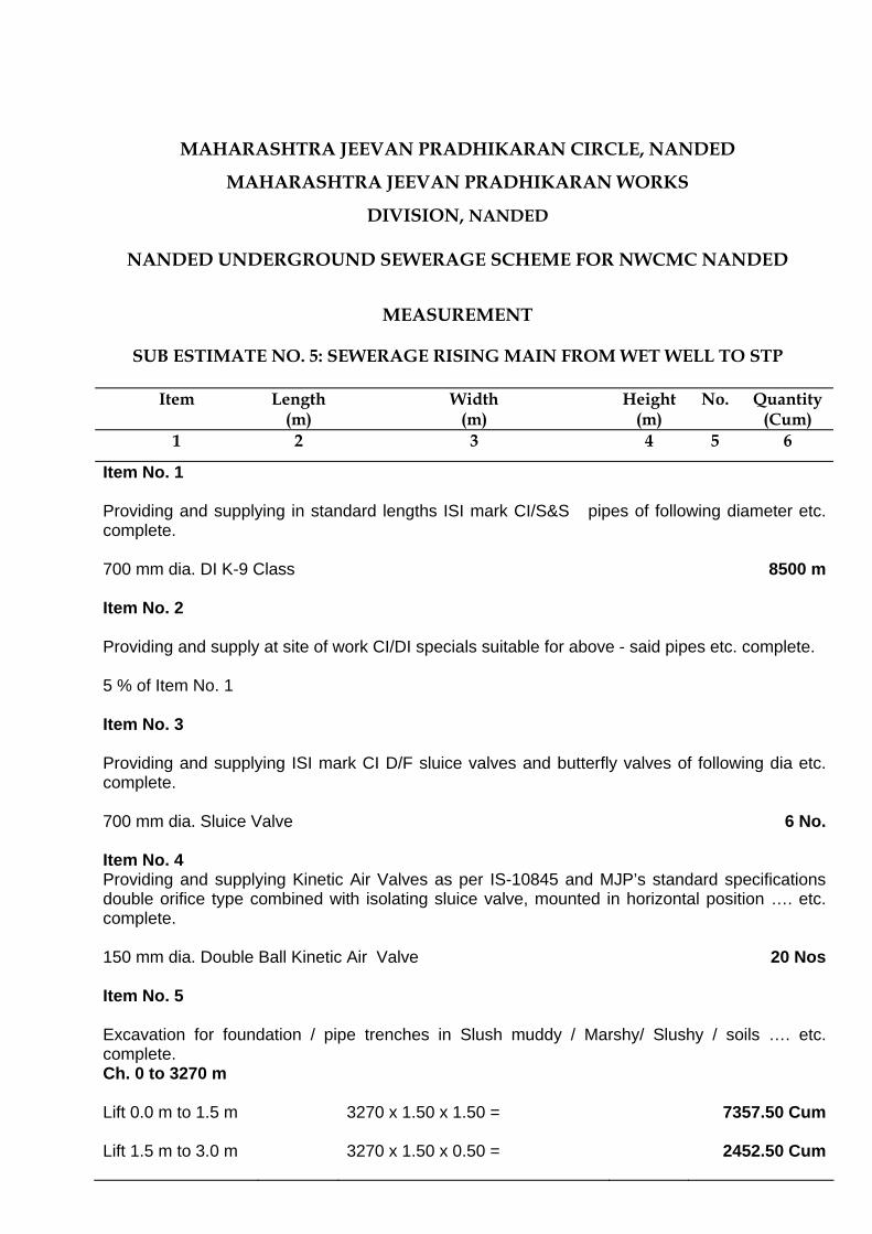
MAHARASHTRA JEEVAN PRADHIKARAN CIRCLE, NANDED
MAHARASHTRA JEEVAN PRADHIKARAN WORKS
DIVISION, NANDED
NANDED UNDERGROUND SEWERAGE SCHEME FOR NWCMC NANDED
MEASUREMENT
SUB ESTIMATE NO. 5: SEWERAGE RISING MAIN FROM WET WELL TO STP
Item Length
(m) Width
(m) Height
(m) No. Quantity
(Cum) 1 2 3 4 5 6
Item No. 1
Providing and supplying in standard lengths ISI mark CI/S&S pipes of following diameter etc. complete. 700 mm dia. DI K-9 Class
8500 m
Item No. 2
Providing and supply at site of work CI/DI specials suitable for above - said pipes etc. complete. 5 % of Item No. 1
Item No. 3
Providing and supplying ISI mark CI D/F sluice valves and butterfly valves of following dia etc. complete. 700 mm dia. Sluice Valve
6 No.
Item No. 4 Providing and supplying Kinetic Air Valves as per IS-10845 and MJP’s standard specifications double orifice type combined with isolating sluice valve, mounted in horizontal position …. etc. complete. 150 mm dia. Double Ball Kinetic Air Valve
20 Nos
Item No. 5
Excavation for foundation / pipe trenches in Slush muddy / Marshy/ Slushy / soils …. etc. complete. Ch. 0 to 3270 m
Lift 0.0 m to 1.5 m
3270 x 1.50 x 1.50 = 7357.50 Cum
Lift 1.5 m to 3.0 m
3270 x 1.50 x 0.50 = 2452.50 Cum
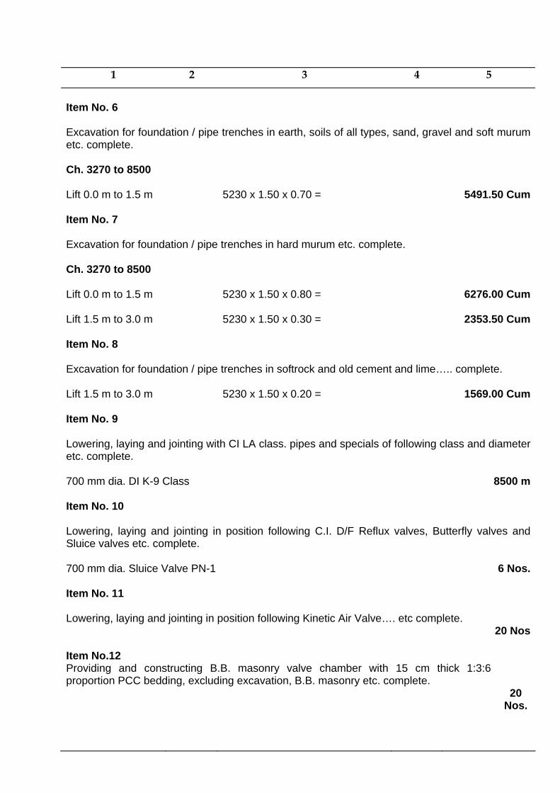
1 2 3 4 5
Item No. 6 Excavation for foundation / pipe trenches in earth, soils of all types, sand, gravel and soft murum etc. complete. Ch. 3270 to 8500 Lift 0.0 m to 1.5 m
5230 x 1.50 x 0.70 = 5491.50 Cum
Item No. 7
Excavation for foundation / pipe trenches in hard murum etc. complete. Ch. 3270 to 8500 Lift 0.0 m to 1.5 m
5230 x 1.50 x 0.80 = 6276.00 Cum
Lift 1.5 m to 3.0 m
5230 x 1.50 x 0.30 = 2353.50 Cum
Item No. 8
Excavation for foundation / pipe trenches in softrock and old cement and lime….. complete. Lift 1.5 m to 3.0 m
5230 x 1.50 x 0.20 = 1569.00 Cum
Item No. 9
Lowering, laying and jointing with CI LA class. pipes and specials of following class and diameter etc. complete. 700 mm dia. DI K-9 Class
8500 m
Item No. 10
Lowering, laying and jointing in position following C.I. D/F Reflux valves, Butterfly valves and Sluice valves etc. complete. 700 mm dia. Sluice Valve PN-1
6 Nos.
Item No. 11
Lowering, laying and jointing in position following Kinetic Air Valve…. etc complete. 20 Nos
Item No.12 Providing and constructing B.B. masonry valve chamber with 15 cm thick 1:3:6 proportion PCC bedding, excluding excavation, B.B. masonry etc. complete.
20 Nos.
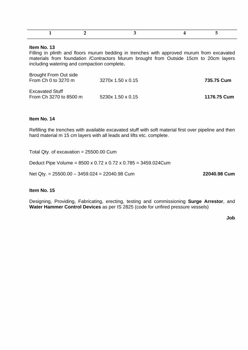
1 2 3 4 5
Item No. 13 Filling in plinth and floors murum bedding in trenches with approved murum from excavated materials from foundation /Contractors Murum brought from Outside 15cm to 20cm layers including watering and compaction complete. Brought From Out side From Ch 0 to 3270 m 3270x 1.50 x 0.15 735.75 Cum Excavated Stuff From Ch 3270 to 8500 m 5230x 1.50 x 0.15 1176.75 Cum Item No. 14
Refilling the trenches with available excavated stuff with soft material first over pipeline and then hard material m 15 cm layers with all leads and lifts etc. complete. Total Qty. of excavation = 25500.00 Cum
Deduct Pipe Volume = 8500 x 0.72 x 0.72 x 0.785 = 3459.024Cum
Net Qty. = 25500.00 – 3459.024 = 22040.98 Cum
22040.98 Cum
Item No. 15
Designing, Providing, Fabricating, erecting, testing and commissioning Surge Arrestor, and Water Hammer Control Devices as per IS 2825 (code for unfired pressure vessels) Job
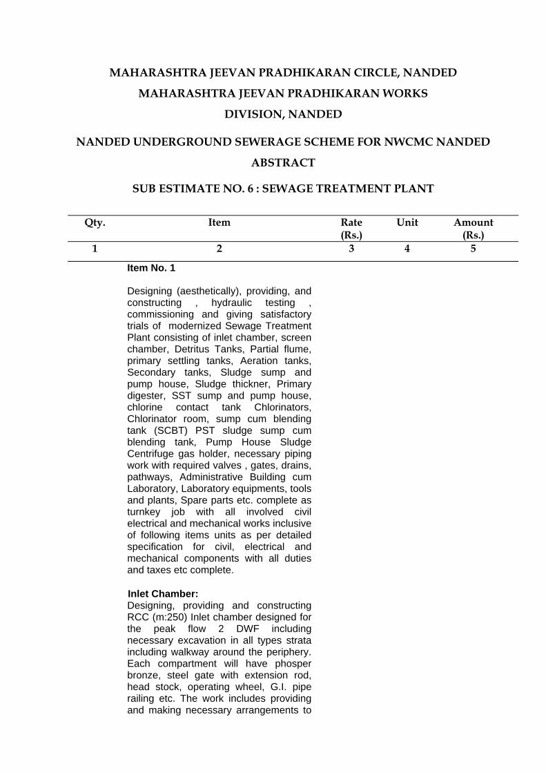
MAHARASHTRA JEEVAN PRADHIKARAN CIRCLE, NANDED
MAHARASHTRA JEEVAN PRADHIKARAN WORKS
DIVISION, NANDED
NANDED UNDERGROUND SEWERAGE SCHEME FOR NWCMC NANDED
ABSTRACT
SUB ESTIMATE NO. 6 : SEWAGE TREATMENT PLANT
Qty. Item Rate
(Rs.) Unit Amount
(Rs.) 1 2 3 4 5
Item No. 1
Designing (aesthetically), providing, and constructing , hydraulic testing , commissioning and giving satisfactory trials of modernized Sewage Treatment Plant consisting of inlet chamber, screen chamber, Detritus Tanks, Partial flume, primary settling tanks, Aeration tanks, Secondary tanks, Sludge sump and pump house, Sludge thickner, Primary digester, SST sump and pump house, chlorine contact tank Chlorinators, Chlorinator room, sump cum blending tank (SCBT) PST sludge sump cum blending tank, Pump House Sludge Centrifuge gas holder, necessary piping work with required valves , gates, drains, pathways, Administrative Building cum Laboratory, Laboratory equipments, tools and plants, Spare parts etc. complete as turnkey job with all involved civil electrical and mechanical works inclusive of following items units as per detailed specification for civil, electrical and mechanical components with all duties and taxes etc complete. Inlet Chamber: Designing, providing and constructing RCC (m:250) Inlet chamber designed for the peak flow 2 DWF including necessary excavation in all types strata including walkway around the periphery. Each compartment will have phosper bronze, steel gate with extension rod, head stock, operating wheel, G.I. pipe railing etc. The work includes providing and making necessary arrangements to
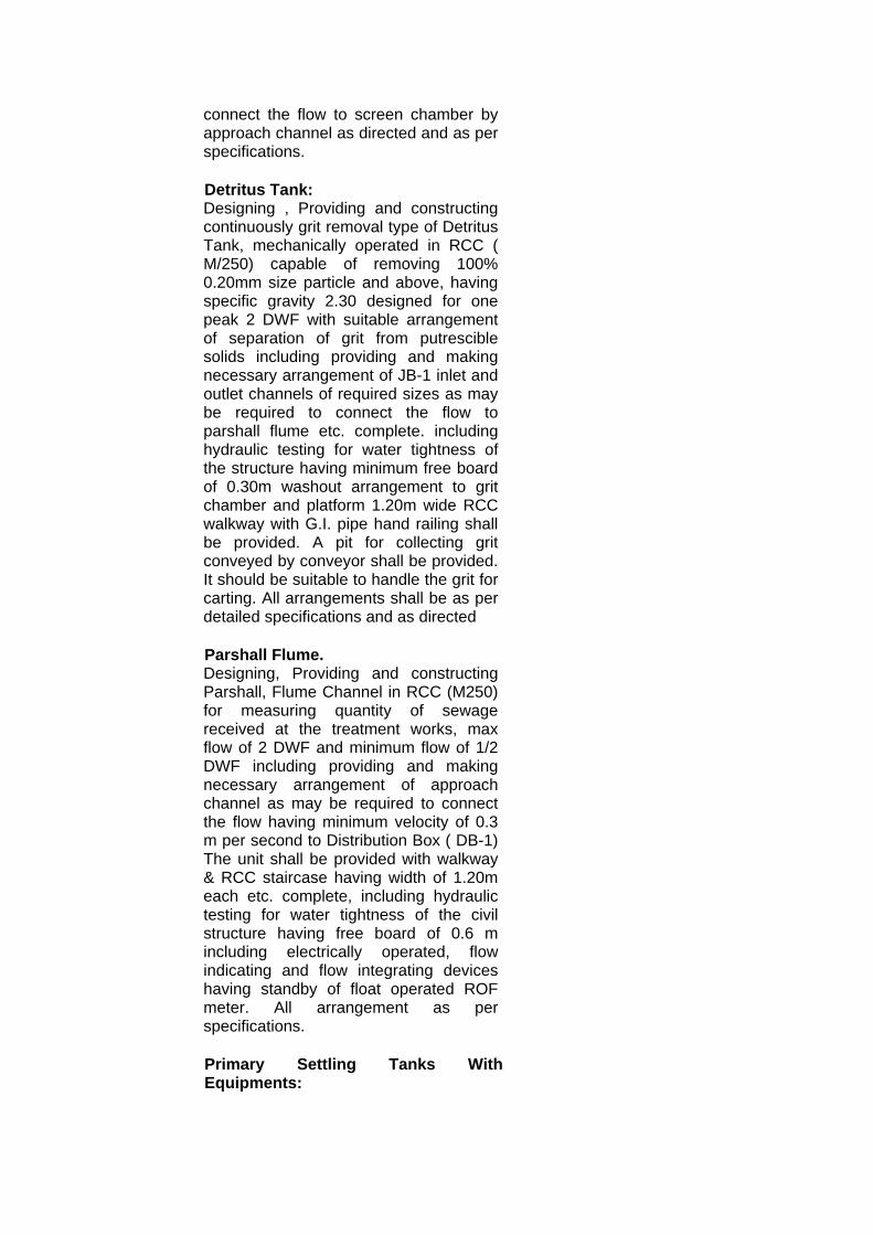
connect the flow to screen chamber by approach channel as directed and as per specifications. Detritus Tank: Designing , Providing and constructing continuously grit removal type of Detritus Tank, mechanically operated in RCC ( M/250) capable of removing 100% 0.20mm size particle and above, having specific gravity 2.30 designed for one peak 2 DWF with suitable arrangement of separation of grit from putrescible solids including providing and making necessary arrangement of JB-1 inlet and outlet channels of required sizes as may be required to connect the flow to parshall flume etc. complete. including hydraulic testing for water tightness of the structure having minimum free board of 0.30m washout arrangement to grit chamber and platform 1.20m wide RCC walkway with G.I. pipe hand railing shall be provided. A pit for collecting grit conveyed by conveyor shall be provided. It should be suitable to handle the grit for carting. All arrangements shall be as per detailed specifications and as directed Parshall Flume. Designing, Providing and constructing Parshall, Flume Channel in RCC (M250) for measuring quantity of sewage received at the treatment works, max flow of 2 DWF and minimum flow of 1/2 DWF including providing and making necessary arrangement of approach channel as may be required to connect the flow having minimum velocity of 0.3 m per second to Distribution Box ( DB-1) The unit shall be provided with walkway & RCC staircase having width of 1.20m each etc. complete, including hydraulic testing for water tightness of the civil structure having free board of 0.6 m including electrically operated, flow indicating and flow integrating devices having standby of float operated ROF meter. All arrangement as per specifications. Primary Settling Tanks With Equipments:
Designing, Providing, constructing and hydraulic testing in RCC (M-250) water tight Primary Settling Tanks of 1 DWF capacity with feed chamber sludge and effluent chamber, base adequately supported providing 1.20 m wide clear peripheral and approach walkway inter connecting C.I. double flanged pipes from feed chamber of the clarifier distribution well grouting wherever necessary, including foundation etc. as per specification water depth at outer side shall be minimum 3.0 meter weir loading shall not be greater than 125cum DMF for average flow Bottom slope shall be 1:12 The floor of clarifier shall have 40mm thick ( min) screed course of cement grout of mix C.M.1:2 Detention period shall be 2.25 hrs. dispersion box and stiffened weir plate made of mild steel plate not less than 8mm thick, anticorrosive epoxy paint on both faces shall be provided Minimum free board of 0.50 m be provided it includes inlet pipe from distribution chamber, central shaft inlet baffle outlet chamber Scum remover, skimming devices scum chamber, connecting channel from PST outlet chamber, to db-2 as per detailed specifications. Aeration Tank (AT) Desiging, Providing and constructing in RCC mix ( M-250) Aeration Tank in compartments to handle combined flow of 1 DWF incoming flow and recirculation flow including construction of inlet, outlet and distribution chamber DB-3 and providing 1.20 M wide clear peripherial and approach walkways, expansion joints wherever necessary, including foundation etc. as per specification. Peak factor shall be 2, F/M ration shall be 0.40 low speed aerator speed between 20 to 100 RPM recirculation flow @ 50% and free board 0.60m, Depth ( SWD) 3.50m ,minimum D.O. level at A.T. 2 Mg/Lit MLVSS concentration shall be 2500mg/Lit and MLVSS concentration shall bw 2000 Mg/Lit, HRT shall be 4 to 6 hours and STR 6-8 days. It should have compartents for washing oxygen transfer capacity of mechanical aerator shall not be less than 1.5 Kg/KWH, BOD of
effluent 20mg/lit with input to aerator 0.15, to 0.30 Kwh/ 1000 cum of Aeration tank. All related works shall be as per detailed specification.
Secondary Settling Tanks with equipment. Designing, Providing and constructing in RCC )M:250) water tight Secondary settling tank having detention period 2 hours and SWD shall be 4.20 meter. The effluent BOD and SS from the secondary clarifier shall not be more then 20 Mg/lit and 30mg/lit. respectively. It should be hydraulically tested, bottom floor slope of 1:12 and fee board of 0.60m minimum Dispersion box shall be made of Mild Steel plate not less then 8mm thick with anticorrosive epoxy paint from both faces and well stiffened. The sewage admitted at the centre flowing upward and outwards towards periphery be slowly and continuously collected towards a convenient discharge point near centre by a rotating wheel arm. The Clarifier will be complete with end drive half rotating bridge structural steel rake, over flow weir, walkway diffuser, over load alarms, having push bottoms, starters for the clarifier, walkway and the suitable sludge withdrawing arrangement with flush valve capable of withdrawing moisture content not more than 97% to 98% sloping floor shall have 40mm thickness (Minimum), screed course of cement grout of mix 1 cement :2 sand, rotating sludge scrapper mechanism filled with squeezes including providing and making necessary arrangements to connect the flow to outlet chamber (DB-4)
then the gravity main for final diaposal and as per detailed specification and obligatory provision. All other arrangements shall be as per detailed specification.
Sludge Thickner with equipments: Designing providing and constructing water tight of Sludge Thickner (Gravity type) including foundation in RCC (M-250) with inlet and outlet chamber, influent well, inlet and outlet pipes, with sludge pit and sludge removal arrangement, grouting wherever necessary with walkway all around of 1.20m width, G.I. pipe railing interconnecting CI pipes all complete as per specification Detention time 24 hours. SWD shall be 4.25 meter with necessary fixed bridge scraper arrangement as per detailed specification and necessary inlet and outlet arrangement. All other arrangement as per detailed specification. Primary Digestor with mixer equipment( Fixed Cover) Designing, Providing and constructing unit of water tight and gas tight Primary Digester suitable for 1 DWF plant and complete with pipe gallery, building staircase for access from dome of digester into inside staircase, walkways at springing levels etc. walls and base slab being in RCC M-250 domes in structural concrete including providing burners and civil works for gas collection, grouting wherever necessary etc. complete as per specification. It should be designed from min 9o C and max. 45o
C and minimum detention time of 30 days, water depth shall not be more then 8.5 m free board shall be 0.6m with inlet
and outlet arrangement of C.I. flanged pipes including giving hydraulic testing and air tightness testing. The item includes works for colleting Gas and Gas burner as per specification.
Secondary Digester with equipment( Fixed cover) Designing ,Providing and constructing including foundation unit of watertight and gastight Secondary Digester to deal with I DWF complete with pipe gallery, building, staircase for access from dome of digester into inside, staircase to walways at springing levels etc. Walls and base slab and domes being in RCC M-250, providing arrangement for digested sludge from digesters to centrifuge , providing burners and civil works for gas collection grouting wherever necessary etc.complete. as per specification and obligatory provision All other arrangements as per detailed specifications. S.S.T.Sump and Pump House with recirculation Pumps and Sludge Pumps to Digester: Designing, Providing and constructing sump & Pump house of requisite capacity with ceiling height not less than 6 M Sludge stream for recirculation to aeration tank and excess sludge to SCBT including C.I. Piping to carry this flow to sump as per detailed specification and as directed by Enginer-in-charge. Chlorine Contact Tank:
Designing, Providing and Constructing Chlorine Contract chamber of adequate capacity to deal with 1 DWF. Average flow. The chlorine contact tank should be of 30 minutes capacity during average flow to achieve 99.99% coliform reduction. Chlorine dose shall be maintained as per standard provision including provisions including designing, providing and constructing water supply arrangement for chlorination, including providing dewatering and bypass arrangments joiting to final effluent main and outlet weir etc. complete The effluent quality should match with the standard laid donw my Maharashtra Water Pollution Control Board and as per the obligatory provision and detailed specification and as directed by Engineer-incharge. Chlorinator and chlorinator Room/ Tonner Room Designing, Providing and constructing chlorinators vaccum type 2 Nos. each having capacity of 10 Kg/Hr. as per obligatory provision and detailed specification with necessary provision of chlorinator room having floor area not less than 30 Sq.m including automatic residual chlorine controller with actuator and residual chlorine analyser including cost of chlorine cylinder, piping valves measuring and controlling equipments, safety devices, lifting equipments, etc. complete. as per I.S.-10553 ( Part/II) 1982 The tonner room should have 3 MT capacity crane for loading and unloading facility. Tonner storage should distrincitly isolated and should be for minimum 10 Tonners space and arrangement as per gas laws 1981 and factory act shall be provided, and all other matching amenities be provided, 5 MT gantry shall be provided for full length of Tonner room at 6 m height from floor level, with/ outlet chamber and treated effluet outlet channel etc. complete. as per detailed specification. Sump Cum Blending Tank ( SCBT) Designing providing and constructing sump cum blending tank of appropriate size and detention time with free board of 0.60 m The slope of floor 1:4 with suction pit at the cnetre as per detailed specification and obligatory requirements

P.S.T. Sump cum Blending Tank, Pump House with re-recirculation pumps Designing, providing and constructing pump house of appropriate size with pumps ,ceiling height minimum 6m over the circular sump for discharging the sludge to thickner and recycling of flow for blending, with C.I. Piping etc. complete. As per detailed specification Sludge Centrifuge Room with Centrifuges:- Designing, providing and constructing and installing including foundation etc. Sludge Centrifuge to handle the sludge flow of one day in one hour per unit with sludge dewatering unit drain etc. complete as per specification. Sludge centrigure with all necessary arrangement as per detailed specifications mentioned in Volume-II and Volume-III of tender and obligatory provisions, be provided with satisfactory functioning. Gas Hoder: Designing, Providing and constructing gas holder having gas collection system gas flow meter and gas burner with floating dome arrangement and storage time 6 hrs. to be constructed in M-250 having appropriate diameter as per detailed specification and obligatory provisions. The flating dome shall be of 8mm thick M.S. plate minimum and shall be provided with two coats of anticorrosive epoxy coating from both faces. Outfall Sewer : Designing providing and constructing approprate Outfall Sewer of RCC NP-2 pipe to discharge treated effluent, untreated effluent from outlet chamber ( after secondary clarifier) to the local nalla at a point shown on the drawing including necessary chambers for inspection/ cleaning including necessary excavtion dewatering refilling, concrete encasing/ bedding ,concrete steps to reach the nalla bed level. pitching and energy dissipation chamber in the nalla portion etc. complete upto 50 m length RCC NP-2 pipe line and inclding all above items
Piping work in C.I.L.A. class including Sluice valves, Reflux valves M.S.Gate.Providing laying and jointing pipe other than those already included in the above items for interconnection by-pass drains etc. of all units including adequate numbers of manhole chambers. The item includes excavation, refilling and hydraulic testing of pipes, valves, gates, accessories and cost of jointing material . The item includes required channels with gates for interconnection of units by pass drains etc. for all units and as directed etc. complete. as per detailed specification. Administrative Building Cum Laboratory ( G+ 1) Designing, providing and constructing Administrative Building office cum Laboratory including stores. This shall be a building having appropriate Carpet area at ground floor and at first floor complete as per specifications including necessary excavation , foundation in RCC M-200 framed structure, B.B. Masonary ( II-Class in C.M. 1:6) 20mm cement plaster in C.M. 1:3, inside and outside painting ,Alluminium door and window with glass pannels mosaic tile flooring and skirting and all other allied items, fixtures fastening electrification arrangement water supply arrangement etc. complete. The building will have laboratory on upper flor of administrative building and should be so centralised that it should not be attached with any units but should have complete control of every unit as per Laboratory Equipment, beautification, telephone and intercom arrangement and wireless system etc. complete. B) Primary and secondary treatment -with digesters , sludge drying beds etc. complete.
(CSR 2005-06 of Page No. 215, Item No.4 b)
27.00 MLD
For 20 MLD Rs. 427.60 lakh
427.60
lakh
For 20
mld
5,58,12,750.00

20 MLD to 27.0 MLD 7.00 MLD @ Rs. 14.85 lakh per mld Rs. 103.95 lakh Total for 27.0 mld Rs. 531.55 lakh Add for Municipal Corporation Limits Rs. 558.1275 lakh
14.85 lakh Mld
Total Rs. 5,58,12,750.00 Add 1 % Insurance 5,58,127.50 5,63,70,877.50 Add 5 % Contingencies 28,18,543.88
Total Rs. 5,91,89,421.38 Add 2% Works & Establishment Charges 11,83,788.43 Total Rs. 6,03,73,209.81
Say Rs. 6,03,73,300.00 (Rs. Six Crore Three Lacs Seventy Three Thousand Three Hundred Only) For Sungrace Engineering Projects Pvt. Ltd., Pune (Consulting Engineer)
Sectional Engineer Sub Divisional Engineer, MJP Works Sub Dn, No. 2,
Nanded
Executive Engineer MJP Works Dn., Nanded

1 2 3 4 5
MAHARASHTRA JEEVAN PRADHIKARAN CIRCLE, NANDED
MAHARASHTRA JEEVAN PRADHIKARAN WORKS
DIVISION, NANDED
NANDED UNDERGROUND SEWERAGE SCHEME FOR NWCMC NANDED
ABSTRACT
SUB ESTIMATE NO. 6 : SEWAGE TREATMENT PLANT
Qty. Item Rate
(Rs.) Unit Amount
(Rs.) 1 2 3 4 5
Item No. 1
Designing (aesthetically), providing, and constructing , hydraulic testing , commissioning and giving satisfactory trials of modernized Sewage Treatment Plant consisting of inlet chamber, screen chamber, Detritus Tanks, Partial flume, primary settling tanks, Aeration tanks, Secondary tanks, Sludge sump and pump house, Sludge thickner, Primary digester, SST sump and pump house, chlorine contact tank Chlorinators, Chlorinator room, sump cum blending tank (SCBT) PST sludge sump cum blending tank, Pump House Sludge Centrifuge gas holder, necessary piping work with required valves , gates, drains, pathways, Administrative Building cum Laboratory, Laboratory equipments, tools and plants, Spare parts etc. complete as turnkey job with all involved civil electrical and mechanical works inclusive of following items units as per detailed specification for civil, electrical and mechanical components with all duties and taxes etc complete. Inlet Chamber: Designing, providing and constructing RCC (m:250) Inlet chamber designed for the peak flow 2 DWF including necessary excavation in all types strata including walkway around the periphery. Each compartment will have phosper bronze, steel gate with extension rod, head stock, operating wheel, G.I. pipe railing etc. The work includes providing and making necessary arrangements to

1 2 3 4 5
connect the flow to screen chamber by approach channel as directed and as per specifications. Detritus Tank: Designing , Providing and constructing continuously grit removal type of Detritus Tank, mechanically operated in RCC ( M/250) capable of removing 100% 0.20mm size particle and above, having specific gravity 2.30 designed for one peak 2 DWF with suitable arrangement of separation of grit from putrescible solids including providing and making necessary arrangement of JB-1 inlet and outlet channels of required sizes as may be required to connect the flow to parshall flume etc. complete. including hydraulic testing for water tightness of the structure having minimum free board of 0.30m washout arrangement to grit chamber and platform 1.20m wide RCC walkway with G.I. pipe hand railing shall be provided. A pit for collecting grit conveyed by conveyor shall be provided. It should be suitable to handle the grit for carting. All arrangements shall be as per detailed specifications and as directed Parshall Flume. Designing, Providing and constructing Parshall, Flume Channel in RCC (M250) for measuring quantity of sewage received at the treatment works, max flow of 2 DWF and minimum flow of 1/2 DWF including providing and making necessary arrangement of approach channel as may be required to connect the flow having minimum velocity of 0.3 m per second to Distribution Box ( DB-1) The unit shall be provided with walkway & RCC staircase having width of 1.20m each etc. complete, including hydraulic testing for water tightness of the civil structure having free board of 0.6 m including electrically operated, flow indicating and flow integrating devices having standby of float operated ROF meter. All arrangement as per specifications. Primary Settling Tanks With Equipments : Designing, Providing, constructing and hydraulic testing in RCC (M-250) water tight Primary Settling Tanks of 1 DWF capacity with feed chamber sludge and
1 2 3 4 5
effluent chamber, base adequately supported providing 1.20 m wide clear peripheral and approach walkway inter connecting C.I. double flanged pipes from feed chamber of the clarifier distribution well grouting wherever necessary, including foundation etc. as per specification water depth at outer side shall be minimum 3.0 meter weir loading shall not be greater than 125cum DMF for average flow Bottom slope shall be 1:12 The floor of clarifier shall have 40mm thick ( min) screed course of cement grout of mix C.M.1:2 Detention period shall be 2.25 hrs. dispersion box and stiffened weir plate made of mild steel plate not less than 8mm thick, anticorrosive epoxy paint on both faces shall be provided Minimum free board of 0.50 m be provided it includes inlet pipe from distribution chamber, central shaft inlet baffle outlet chamber Scum remover, skimming devices scum chamber, connecting channel from PST outlet chamber, to db-2 as per detailed specifications. Aeration Tank (AT) Desiging, Providing and constructing in RCC mix ( M-250) Aeration Tank in compartments to handle combined flow of 1 DWF incoming flow and recirculation flow including construction of inlet, outlet and distribution chamber DB-3 and providing 1.20 M wide clear peripherial and approach walkways, expansion joints wherever necessary, including foundation etc. as per specification. Peak factor shall be 2, F/M ration shall be 0.40 low speed aerator speed between 20 to 100 RPM recirculation flow @ 50% and free board 0.60m, Depth ( SWD) 3.50m ,minimum D.O. level at A.T. 2 Mg/Lit MLVSS concentration shall be 2500mg/Lit and MLVSS concentration shall bw 2000 Mg/Lit, HRT shall be 4 to 6 hours and STR 6-8 days. It should have compartents for washing oxygen transfer capacity of mechanical aerator shall not be less than 1.5 Kg/KWH, BOD of effluent 20mg/lit with input to aerator 0.15, to 0.30 Kwh/ 1000 cum of Aeration tank. All related works shall be as per detailed specification
1 2 3 4 5
Secondary Settling Tanks with equipment. Designing, Providing and constructing in RCC )M:250) water tight Secondary settling tank having detention period 2 hours and SWD shall be 4.20 meter. The effluent BOD and SS from the secondary clarifier shall not be more then 20 Mg/lit and 30mg/lit. respectively. It should be hydraulically tested, bottom floor slope of 1:12 and fee board of 0.60m minimum Dispersion box shall be made of Mild Steel plate not less then 8mm thick with anticorrosive epoxy paint from both faces and well stiffened. The sewage admitted at the centre flowing upward and outwards towards periphery be slowly and continuously collected towards a convenient discharge point near centre by a rotating wheel arm. The Clarifier will be complete with end drive half rotating bridge structural steel rake, over flow weir, walkway diffuser, over load alarms, having push bottoms, starters for the clarifier, walkway and the suitable sludge withdrawing arrangement with flush valve capable of withdrawing moisture content not more than 97% to 98% sloping floor shall have 40mmthickness (Minimum), screed course of cement grout of mix 1 cement :2 sand, rotating sludge scrapper mechanism filled with squeezes including providing and making necessary arrangements to connect the flow to outlet chamber (DB-4) then the gravity main for final diaposal and as per detailed specification and obligatory provision. All other arrangements shall be as per detailed specification. Sludge Thickner with equipments: Designing providing and constructing water tight of Sludge Thickner (Gravity type) including foundation in RCC (M-250) with inlet and outlet chamber, influent well, inlet and outlet pipes, with sludge pit and sludge removal arrangement, grouting wherever necessary with walkway all around of 1.20m width, G.I. pipe railing interconnecting CI pipes all complete as per specification Detention time 24 hours. SWD shall be 4.25 meter with necessary
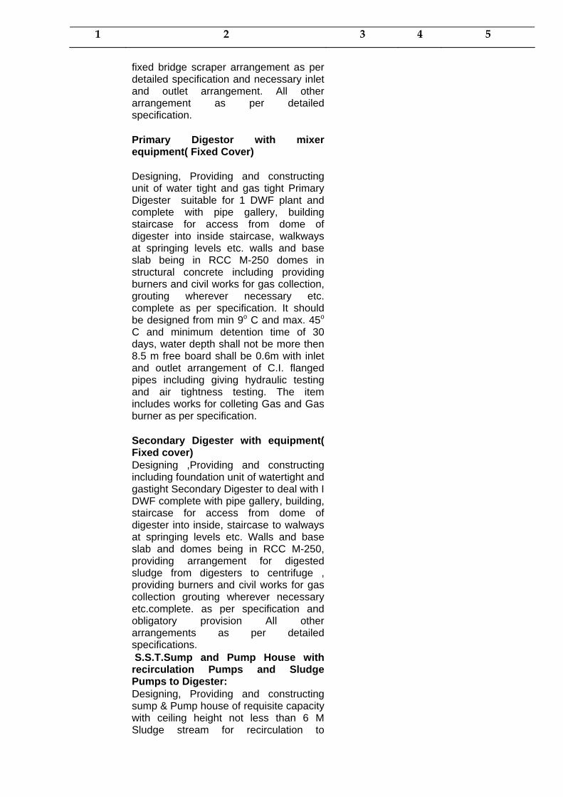
1 2 3 4 5
fixed bridge scraper arrangement as per detailed specification and necessary inlet and outlet arrangement. All other arrangement as per detailed specification. Primary Digestor with mixer equipment( Fixed Cover) Designing, Providing and constructing unit of water tight and gas tight Primary Digester suitable for 1 DWF plant and complete with pipe gallery, building staircase for access from dome of digester into inside staircase, walkways at springing levels etc. walls and base slab being in RCC M-250 domes in structural concrete including providing burners and civil works for gas collection, grouting wherever necessary etc. complete as per specification. It should be designed from min 9o C and max. 45o
C and minimum detention time of 30 days, water depth shall not be more then 8.5 m free board shall be 0.6m with inlet and outlet arrangement of C.I. flanged pipes including giving hydraulic testingand air tightness testing. The item includes works for colleting Gas and Gas burner as per specification. Secondary Digester with equipment( Fixed cover) Designing ,Providing and constructing including foundation unit of watertight and gastight Secondary Digester to deal with I DWF complete with pipe gallery, building, staircase for access from dome of digester into inside, staircase to walways at springing levels etc. Walls and base slab and domes being in RCC M-250, providing arrangement for digested sludge from digesters to centrifuge , providing burners and civil works for gas collection grouting wherever necessary etc.complete. as per specification and obligatory provision All other arrangements as per detailed specifications. S.S.T.Sump and Pump House with recirculation Pumps and Sludge Pumps to Digester: Designing, Providing and constructing sump & Pump house of requisite capacity with ceiling height not less than 6 M Sludge stream for recirculation to
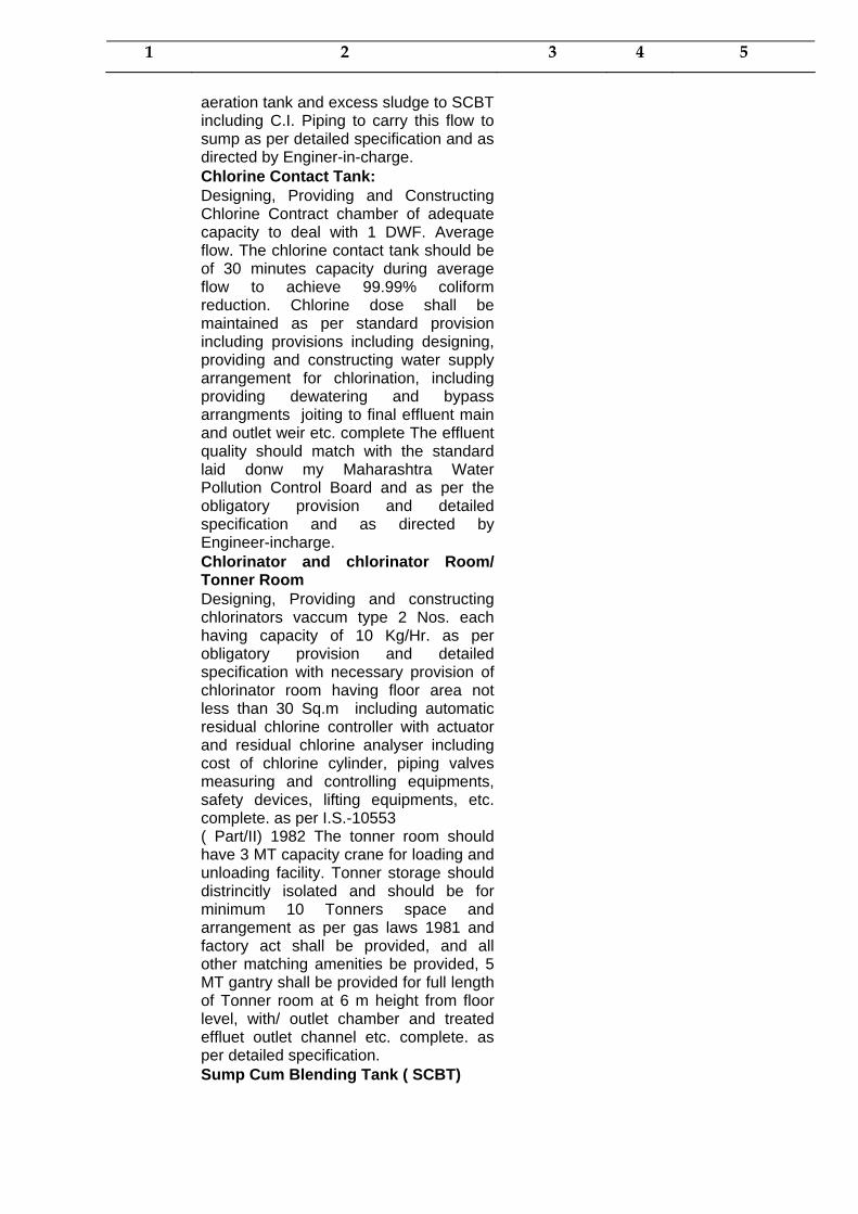
1 2 3 4 5
aeration tank and excess sludge to SCBT including C.I. Piping to carry this flow to sump as per detailed specification and as directed by Enginer-in-charge. Chlorine Contact Tank: Designing, Providing and Constructing Chlorine Contract chamber of adequate capacity to deal with 1 DWF. Average flow. The chlorine contact tank should be of 30 minutes capacity during average flow to achieve 99.99% coliform reduction. Chlorine dose shall be maintained as per standard provision including provisions including designing, providing and constructing water supply arrangement for chlorination, including providing dewatering and bypass arrangments joiting to final effluent main and outlet weir etc. complete The effluent quality should match with the standard laid donw my Maharashtra Water Pollution Control Board and as per the obligatory provision and detailed specification and as directed by Engineer-incharge. Chlorinator and chlorinator Room/ Tonner Room Designing, Providing and constructing chlorinators vaccum type 2 Nos. each having capacity of 10 Kg/Hr. as per obligatory provision and detailed specification with necessary provision of chlorinator room having floor area not less than 30 Sq.m including automatic residual chlorine controller with actuator and residual chlorine analyser including cost of chlorine cylinder, piping valves measuring and controlling equipments, safety devices, lifting equipments, etc. complete. as per I.S.-10553 ( Part/II) 1982 The tonner room should have 3 MT capacity crane for loading and unloading facility. Tonner storage should distrincitly isolated and should be for minimum 10 Tonners space and arrangement as per gas laws 1981 and factory act shall be provided, and all other matching amenities be provided, 5 MT gantry shall be provided for full length of Tonner room at 6 m height from floor level, with/ outlet chamber and treated effluet outlet channel etc. complete. as per detailed specification. Sump Cum Blending Tank ( SCBT)

1 2 3 4 5
Designing providing and constructing sump cum blending tank of appropriate size and detention time with free board of 0.60 m The slope of floor 1:4 with suction pit at the cnetre as per detailed specification and obligatory requirements P.S.T. Sump cum Blending Tank, Pump House with re-recirculation pumps Designing, providing and constructing pump house of appropriate size with pumps ,ceiling height minimum 6m over the circular sump for discharging the sludge to thickner and recycling of flow for blending, with C.I. Piping etc. complete. As per detailed specification Sludge Centrifuge Room with Centrifuges:- Designing, providing and constructing and installing including foundation etc. Sludge Centrifuge to handle the sludge flow of one day in one hour per unit with sludge dewatering unit drain etc. complete as per specification. Sludge centrigure with all necessary arrangement as per detailed specifications mentioned in Volume-II and Volume-III of tender and obligatory provisions, be provided with satisfactory functioning. Gas Hoder: Designing, Providing and constructing gas holder having gas collection system gas flow meter and gas burner with floating dome arrangement and storage time 6 hrs. to be constructed in M-250 having appropriate diameter as per detailed specification and obligatory provisions. The flating dome shall be of 8mm thick M.S. plate minimum and shall be provided with two coats of anticorrosive epoxy coating from both faces. Designing providing and constructing approprate Outfall Sewer of RCC NP-2 pipe to discharge treated effluent, untreated effluent from outlet chamber ( after secondary clarifier) to the local nalla at a point shown on the drawing including necessary chambers for inspection/ cleaning including necessary excavtion dewatering refilling, concrete encasing/ bedding ,concrete steps to reach the nalla bed level. pitching and energy

1 2 3 4 5
dissipation chamber in the nalla portion etc. complete upto 50 m length RCC NP-2 pipe line and inclding all above items
Piping work in C.I.L.A. class including Sluice valves, Reflux valves M.S.Gate.Providing laying and jointing pipe other than those already included in the above items for interconnection by-pass drains etc. of all units including adequate numbers of manhole chambers. The item includes excavation, refilling and hydraulic testing of pipes, valves, gates, accessories and cost of jointing material . The item includes required channels with gates for interconnection of units by pass drains etc. for all units and as directed etc. complete. as per detailed specification. Administrative Building Cum Laboratory ( G+ 1) Designing, providing and constructing Administrative Building office cum Laboratory including stores. This shall be a building having appropriate Carpet area at ground floor and at first floor complete as per specifications including necessary excavation , foundation in RCC M-200 framed structure, B.B. Masonary ( II-Class in C.M. 1:6) 20mm cement plaster in C.M. 1:3, inside and outside painting ,Alluminium door and window with glass pannels mosaic tile flooring and skirting and all other allied items, fixtures fastening electrification arrangement water supply arrangement etc. complete. The building will have laboratory on upper flor of administrative building and should be so centralised that it should not be attached with any units but should have complete control of every unit as per Laboratory Equipment, beautification, telephone and intercom arrangement and wireless system etc. complete. B) Primary and secondary treatment -with digesters , sludge drying beds etc. complete.
(CSR 2005-06 of Page No. 215, Item No.4 b)
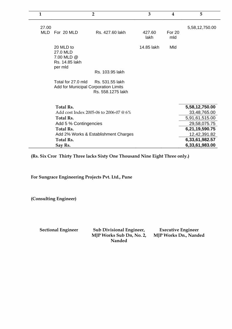
1 2 3 4 5
27.00
MLD
For 20 MLD Rs. 427.60 lakh 20 MLD to 27.0 MLD 7.00 MLD @ Rs. 14.85 lakh per mld Rs. 103.95 lakh Total for 27.0 mld Rs. 531.55 lakh Add for Municipal Corporation Limits Rs. 558.1275 lakh
427.60
lakh
14.85 lakh
For 20
mld
Mld
5,58,12,750.00
Total Rs. 5,58,12,750.00 Add cost Index 2005-06 to 2006-07 @ 6% 33,48,765.00 Total Rs. 5,91,61,515.00 Add 5 % Contingencies 29,58,075.75 Total Rs. 6,21,19,590.75 Add 2% Works & Establishment Charges 12,42,391.82 Total Rs. 6,33,61,982.57 Say Rs. 6,33,61,983.00
(Rs. Six Cror Thirty Three lacks Sixty One Thousand Nine Eight Three only.) For Sungrace Engineering Projects Pvt. Ltd., Pune (Consulting Engineer)
Sectional Engineer Sub Divisional Engineer, MJP Works Sub Dn, No. 2,
Nanded
Executive Engineer MJP Works Dn., Nanded

MAHARASHTRA JEEVAN PRADHIKARAN CIRCLE, NANDED
MAHARASHTRA JEEVAN PRADHIKARAN WORKS
DIVISION, NANDED
NANDED UNDERGROUND SEWERAGE SCHEME FOR NWCMC NANDED
ABSTRACT
SUB ESTIMATE NO. 7 : LAND ACQUISITION
Qty. Item Rate
(Rs.) Unit Amount
(Rs.) 1 2 3 4 5
Item No. 1
6.00
Provision for Land Acquisition Cost, necessary for the wet well Pump House, Sewage Treatment Plant, Staff Quarters etc. complete.
3000000.00
Ha. 1,80,00,000.00
Total Rs. 1,80,00,000.00
(Rs. One Crors Eighty Lakhs Only) For Sungrace Engineering Projects Pvt. Ltd., Pune (Consulting Engineer)
Sectional Engineer Sub Divisional Engineer, MJP Works Sub Dn, No. 2,
Nanded
Executive Engineer MJP Works Dn., Nanded

MAHARASHTRA JEEVAN PRADHIKARAN CIRCLE, NANDED
MAHARASHTRA JEEVAN PRADHIKARAN WORKS
DIVISION, NANDED
NANDED UNDERGROUND SEWERAGE SCHEME FOR NWCMC NANDED
MEASUREMENT
SUB ESTIMATE NO. 7 : LAND ACQUISITION
Item Length (m)
Width (m)
Height (m)
No. Quantity (Cum)
Item No. 1
Provision for Land Acquisition Cost, necessary for the wet well Pump House, Sewage Treatment Plant, Staff Quarters etc. complete. Land required for –
1) Land Required for STP which includes all sub-works of STP, including Administrative Building, Laboratories, Internal Roads, Necessary Staff Quarters etc. Proposed area 2000 sq per MLD
27 x 2000 54000 Sqm
2) Electricity Power Sub Station
30 x 30 = 900 Sqm
3) Pump House 4) Staff Quarters
40 x 40 = 1600 Sqm
500 Sqm 57000 sqm
say 6.00 Ha.
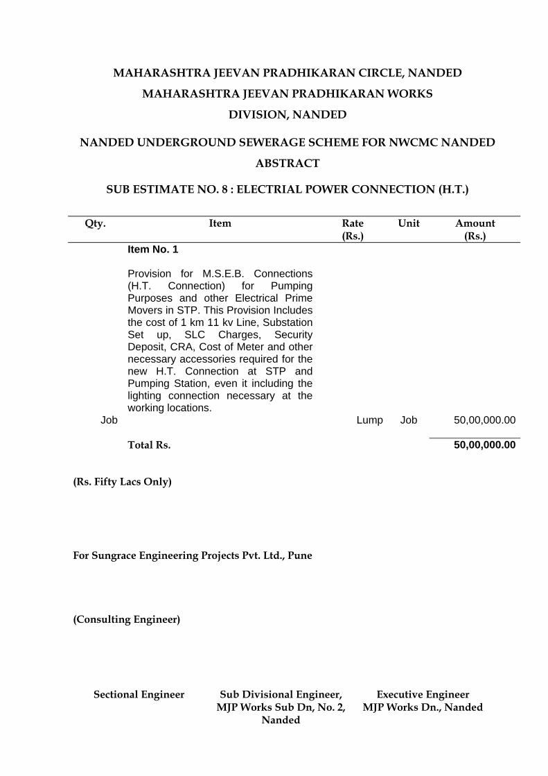
MAHARASHTRA JEEVAN PRADHIKARAN CIRCLE, NANDED
MAHARASHTRA JEEVAN PRADHIKARAN WORKS
DIVISION, NANDED
NANDED UNDERGROUND SEWERAGE SCHEME FOR NWCMC NANDED
ABSTRACT
SUB ESTIMATE NO. 8 : ELECTRIAL POWER CONNECTION (H.T.)
Qty. Item Rate
(Rs.) Unit Amount
(Rs.) Item No. 1
Job
Provision for M.S.E.B. Connections (H.T. Connection) for Pumping Purposes and other Electrical Prime Movers in STP. This Provision Includes the cost of 1 km 11 kv Line, Substation Set up, SLC Charges, Security Deposit, CRA, Cost of Meter and other necessary accessories required for the new H.T. Connection at STP and Pumping Station, even it including the lighting connection necessary at the working locations. Lump
Job 50,00,000.00
Total Rs. 50,00,000.00
(Rs. Fifty Lacs Only) For Sungrace Engineering Projects Pvt. Ltd., Pune (Consulting Engineer)
Sectional Engineer Sub Divisional Engineer, MJP Works Sub Dn, No. 2,
Nanded
Executive Engineer MJP Works Dn., Nanded

MAHARASHTRA JEEVAN PRADHIKARAN CIRCLE, NANDED
MAHARASHTRA JEEVAN PRADHIKARAN WORKS
DIVISION, NANDED
NANDED UNDERGROUND SEWERAGE SCHEME FOR NWCMC NANDED
ABSTRACT
SUB ESTIMATE NO. 9 : ROAD CROSSINGS
Qty. Item Rate
(Rs.) Unit Amount
(Rs.) Item No. 1
Job
Provision for Road Crossing and Railway Crossing of Sewer Lines of Various Diameters as per layout and design, this provision includes Construction of Structures, Royalty Charges if any, Land Rent and other Administrative and legal expenses. etc. complete. Lump
Job 50,00,000.00
Total Rs. 50,00,000.00
(Rs. Fifty Lakh Only) For Sungrace Engineering Projects Pvt. Ltd., Pune (Consulting Engineer)
Sectional Engineer Sub Divisional Engineer, MJP Works Sub Dn, No. 2,
Nanded
Executive Engineer MJP Works Dn., Nanded
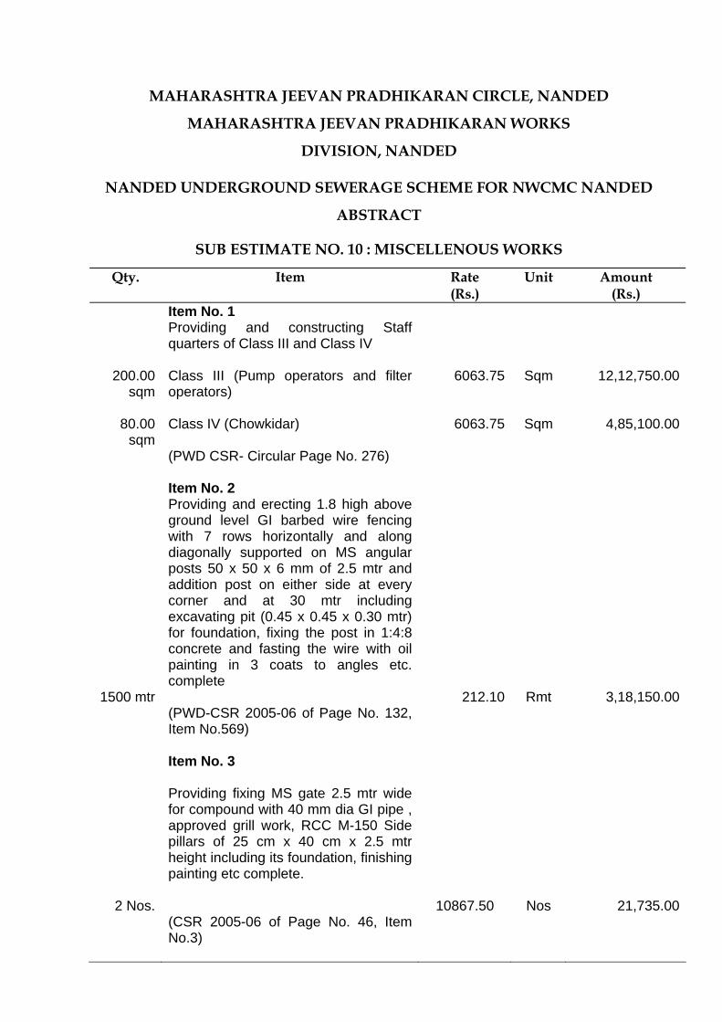
MAHARASHTRA JEEVAN PRADHIKARAN CIRCLE, NANDED
MAHARASHTRA JEEVAN PRADHIKARAN WORKS
DIVISION, NANDED
NANDED UNDERGROUND SEWERAGE SCHEME FOR NWCMC NANDED
ABSTRACT
SUB ESTIMATE NO. 10 : MISCELLENOUS WORKS
Qty. Item Rate (Rs.)
Unit Amount (Rs.)
Item No. 1
200.00 sqm
80.00
sqm
Providing and constructing Staff quarters of Class III and Class IV Class III (Pump operators and filter operators) Class IV (Chowkidar) (PWD CSR- Circular Page No. 276)
6063.75
6063.75
Sqm
Sqm
12,12,750.00
4,85,100.00
Item No. 2
Providing and erecting 1.8 high above ground level GI barbed wire fencing with 7 rows horizontally and along diagonally supported on MS angular posts 50 x 50 x 6 mm of 2.5 mtr and addition post on either side at every corner and at 30 mtr including excavating pit (0.45 x 0.45 x 0.30 mtr) for foundation, fixing the post in 1:4:8 concrete and fasting the wire with oil painting in 3 coats to angles etc. complete
1500 mtr 212.10 Rmt 3,18,150.00 (PWD-CSR 2005-06 of Page No. 132,
Item No.569)
Item No. 3
Providing fixing MS gate 2.5 mtr wide for compound with 40 mm dia GI pipe , approved grill work, RCC M-150 Side pillars of 25 cm x 40 cm x 2.5 mtr height including its foundation, finishing painting etc complete.
2 Nos. 10867.50 Nos 21,735.00 (CSR 2005-06 of Page No. 46, Item
No.3)

Qty. Item Rate (Rs.)
Unit Amount (Rs.)
Item No. 4
Providing fixing Wicket gate 1 mtr wide
for compound with 40 mm dia GI pipe , approved grill work, RCC M-150 Side pillars of 25 cm x 40 cm x 2.5 mtr height including its foundation, finishing painting etc complete.
4 Nos. 5433.75 Nos 21,735.00 (CSR 2005-06 of Page No. 47, Item
No.4)
Item No. 5
900.00
Providing and constructing W.B.M. Road in layers of 75/100 mm compacted thickness, preparation of sub grade, with murum screening necessary testing including supplying and conveying all materials with all leads and lifts spreading, sectioning, artificial watering and compacting in layers with vibrating roller as directed by Engineer-in-charge including maintenance of diversion road during construction Grade II metal 800 mtr 3.75 mtr width and 30 cm thick
350.00
Cum 3,15,000.00
Item No. 6
3000.00
Providing 50 mm thick full grout bituminous road surface including supplying all materials, preparing the existing road surface laying the required thickness of metal layer, heating and spraying bitumen, spreading chips, laying seal coat and compacting etc. complete as directed by Engineer incharge. 800 mtr 3.75 mtr wide using Bulk asphalt 30/40 grade (PWD CSR 2005-06 of Page No. 156, Sr No.707)
112.45
sqm 3,37,350.00
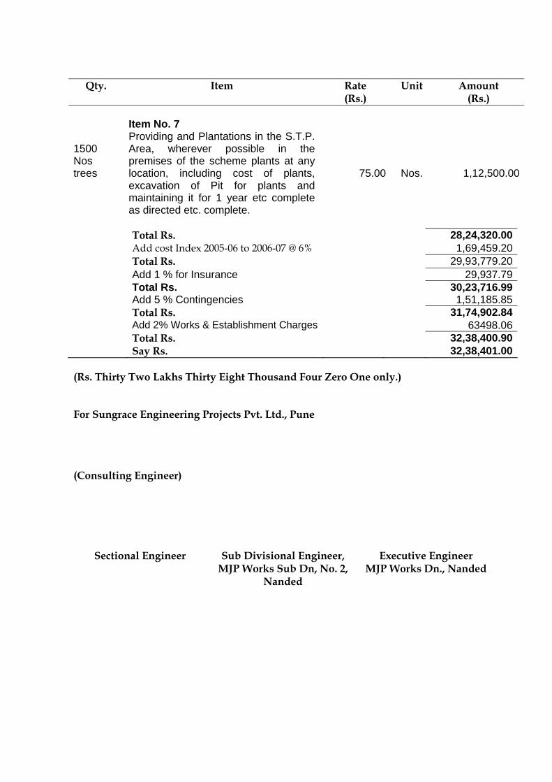
Qty. Item Rate
(Rs.) Unit Amount
(Rs.)
Item No. 7
1500 Nos trees
Providing and Plantations in the S.T.P. Area, wherever possible in the premises of the scheme plants at any location, including cost of plants, excavation of Pit for plants and maintaining it for 1 year etc complete as directed etc. complete.
75.00
Nos. 1,12,500.00
Total Rs. 28,24,320.00 Add cost Index 2005-06 to 2006-07 @ 6% 1,69,459.20 Total Rs. 29,93,779.20 Add 1 % for Insurance 29,937.79 Total Rs. 30,23,716.99 Add 5 % Contingencies 1,51,185.85 Total Rs. 31,74,902.84 Add 2% Works & Establishment Charges 63498.06 Total Rs. 32,38,400.90 Say Rs. 32,38,401.00
(Rs. Thirty Two Lakhs Thirty Eight Thousand Four Zero One only.) For Sungrace Engineering Projects Pvt. Ltd., Pune (Consulting Engineer)
Sectional Engineer Sub Divisional Engineer, MJP Works Sub Dn, No. 2,
Nanded
Executive Engineer MJP Works Dn., Nanded

MAHARASHTRA JEEVAN PRADHIKARAN CIRCLE, NANDED
MAHARASHTRA JEEVAN PRADHIKARAN WORKS
DIVISION, NANDED
NANDED UNDERGROUND SEWERAGE SCHEME FOR NWCMC NANDED
ABSTRACT
SUB ESTIMATE NO. 11 : TRIAL RUN
Qty. Item Rate
(Rs.) Unit Amount
(Rs.) Item No. 1
3 months
Commissioning running & maintaining the scheme to quantities, rated capacity, including managing necessary personnel such as operator, valve-man etc. As per requirements of the scheme and who should administer chemical dose for a period of 3 months with training of personnel spared by MJP / Municipal Corporation and handing over the scheme to Local Authority as directed by Engineer In charge inclusive of Electricity and Fuel Charges for Machinery and Equipments. 15,00,000
Per month
45,00,000.00
Total Rs. 45,00,000.00
(Rs. Fourty Five Lacs Only) For Sungrace Engineering Projects Pvt. Ltd., Pune (Consulting Engineer)
Sectional Engineer Sub Divisional Engineer, MJP Works Sub Dn, No. 2,
Nanded
Executive Engineer MJP Works Dn., Nanded
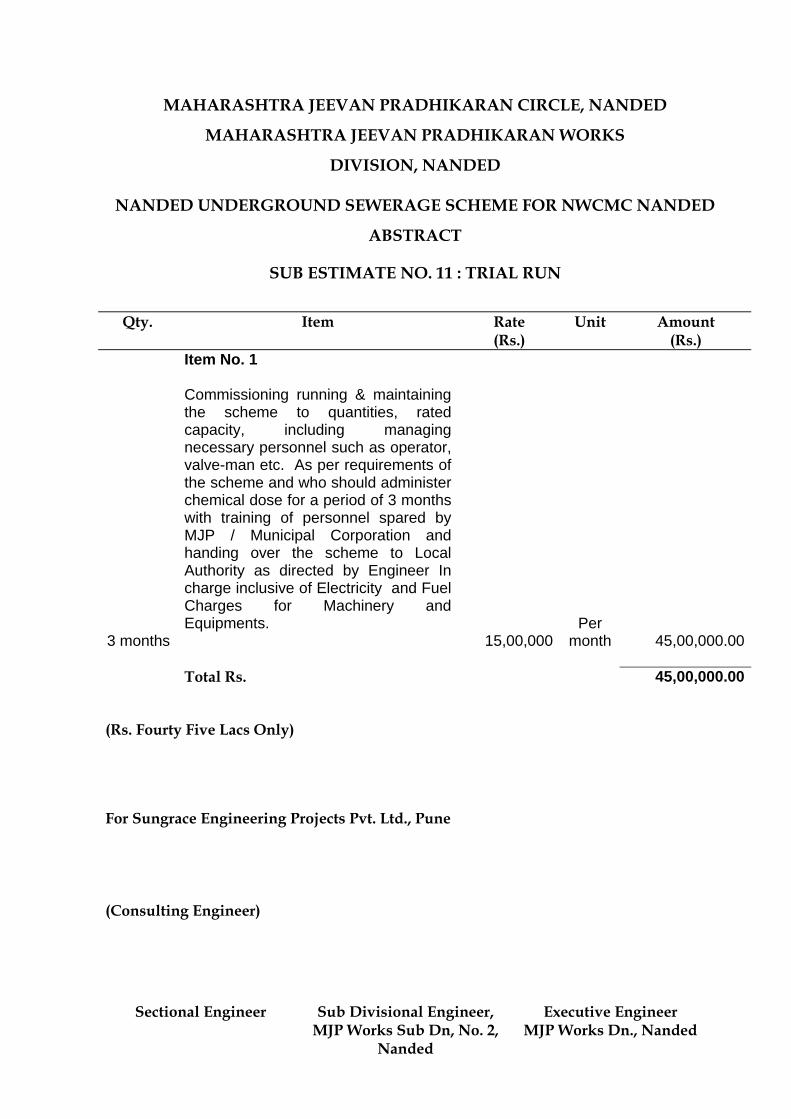

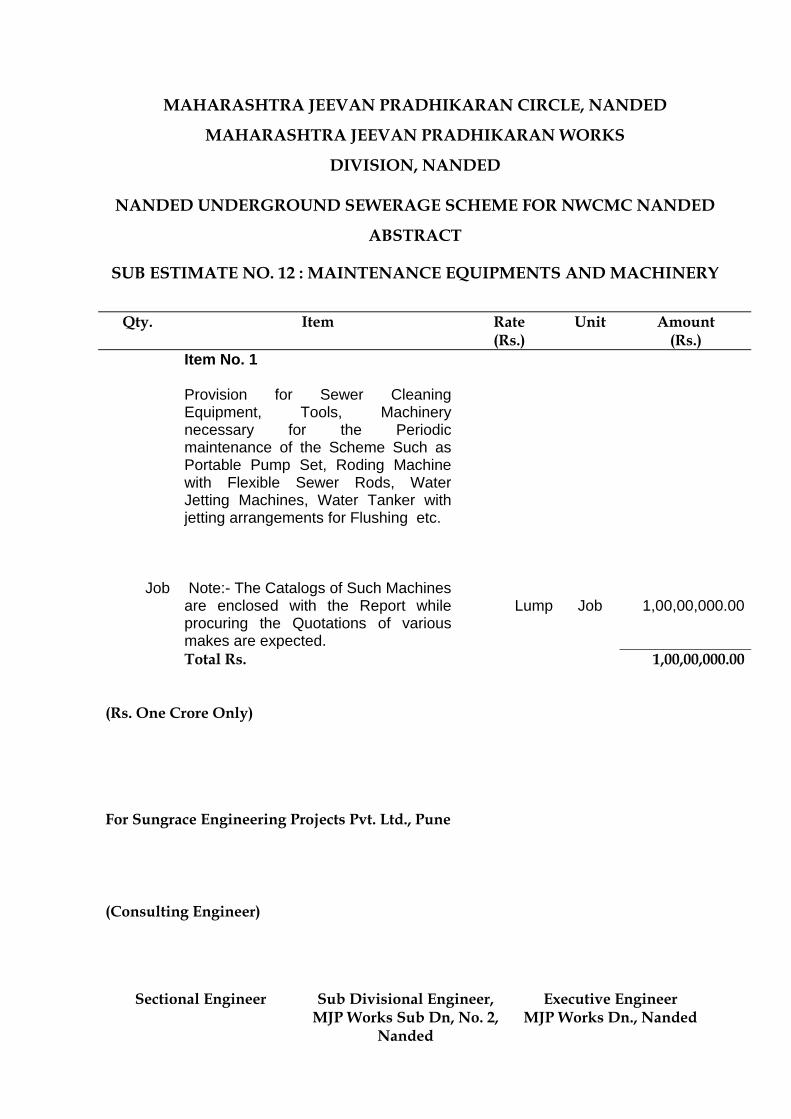
MAHARASHTRA JEEVAN PRADHIKARAN CIRCLE, NANDED
MAHARASHTRA JEEVAN PRADHIKARAN WORKS
DIVISION, NANDED
NANDED UNDERGROUND SEWERAGE SCHEME FOR NWCMC NANDED
ABSTRACT
SUB ESTIMATE NO. 12 : MAINTENANCE EQUIPMENTS AND MACHINERY
Qty. Item Rate
(Rs.) Unit Amount
(Rs.) Item No. 1
Job
Provision for Sewer Cleaning Equipment, Tools, Machinery necessary for the Periodic maintenance of the Scheme Such as Portable Pump Set, Roding Machine with Flexible Sewer Rods, Water Jetting Machines, Water Tanker with jetting arrangements for Flushing etc. Note:- The Catalogs of Such Machines are enclosed with the Report while procuring the Quotations of various makes are expected.
Lump
Job 1,00,00,000.00
Total Rs. 1,00,00,000.00
(Rs. One Crore Only) For Sungrace Engineering Projects Pvt. Ltd., Pune (Consulting Engineer)
Sectional Engineer Sub Divisional Engineer, MJP Works Sub Dn, No. 2,
Nanded
Executive Engineer MJP Works Dn., Nanded
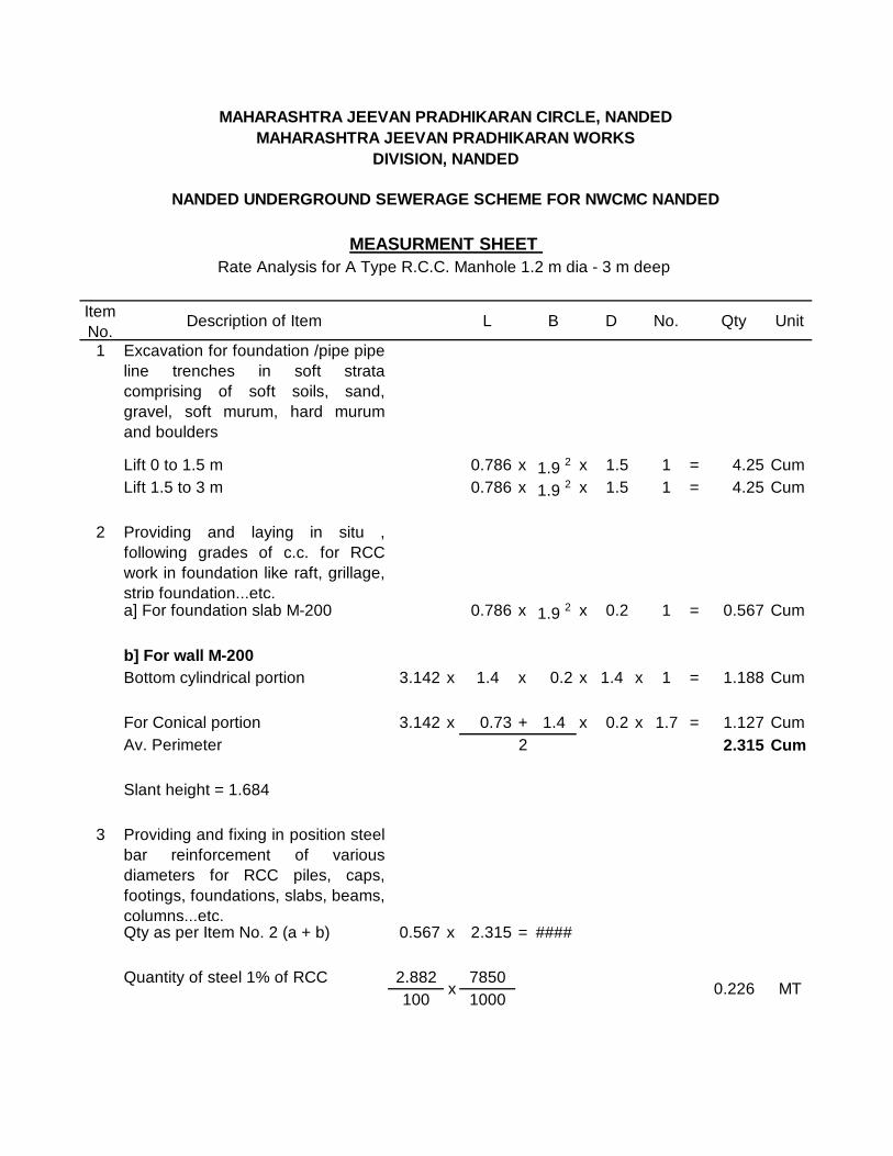
Item No.
Description of Item L B D No. Qty Unit
1 Excavation for foundation /pipe pipeline trenches in soft stratacomprising of soft soils, sand,gravel, soft murum, hard murumand boulders
Lift 0 to 1.5 m 0.786 x 1.9 2 x 1.5 1 = 4.25 CumLift 1.5 to 3 m 0.786 x 1.9 2 x 1.5 1 = 4.25 Cum
2 Providing and laying in situ ,following grades of c.c. for RCCwork in foundation like raft, grillage,strip foundation...etc. a] For foundation slab M-200 0.786 x 1.9 2 x 0.2 1 = 0.567 Cum
b] For wall M-200Bottom cylindrical portion 3.142 x 1.4 x 0.2 x 1.4 x 1 = 1.188 Cum
For Conical portion 3.142 x 0.73 + 1.4 x 0.2 x 1.7 = 1.127 CumAv. Perimeter 2 2.315 Cum
Slant height = 1.684
3 Providing and fixing in position steelbar reinforcement of variousdiameters for RCC piles, caps,footings, foundations, slabs, beams,columns...etc.Qty as per Item No. 2 (a + b) 0.567 x 2.315 = ####
Quantity of steel 1% of RCC 2.882 7850100 1000
MAHARASHTRA JEEVAN PRADHIKARAN CIRCLE, NANDEDMAHARASHTRA JEEVAN PRADHIKARAN WORKS
DIVISION, NANDED
NANDED UNDERGROUND SEWERAGE SCHEME FOR NWCMC NANDED
MEASURMENT SHEET Rate Analysis for A Type R.C.C. Manhole 1.2 m dia - 3 m deep
x 0.226 MT
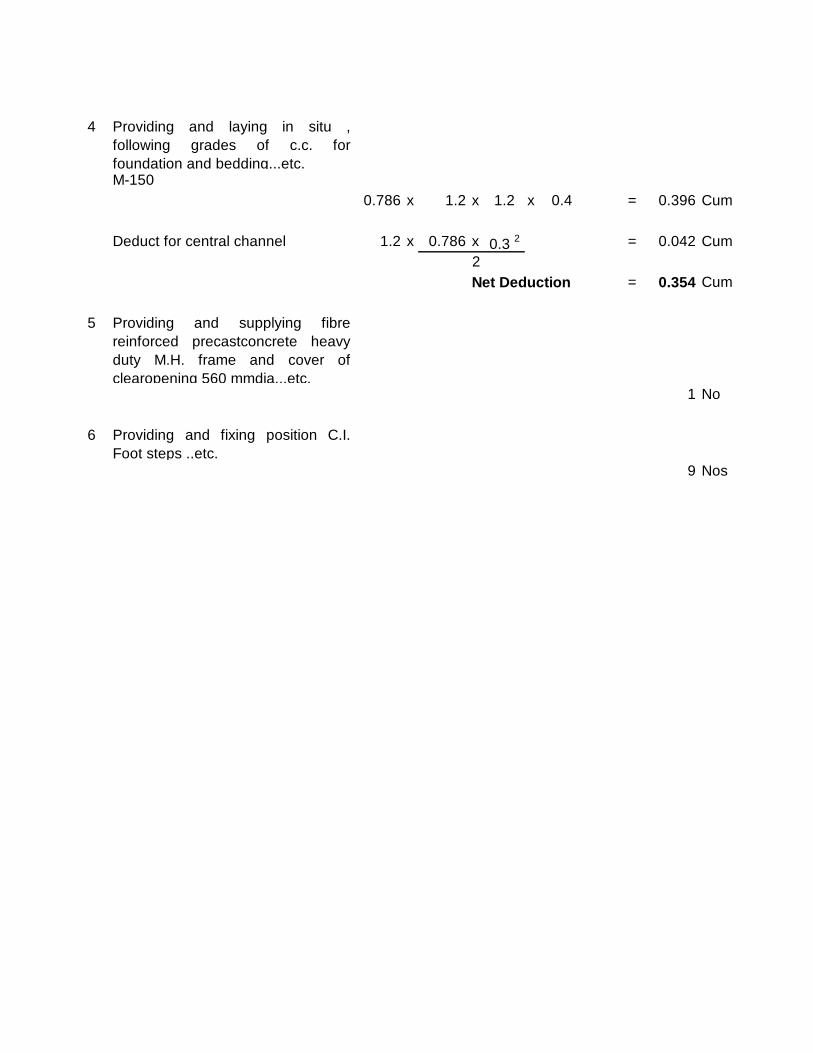
4 Providing and laying in situ ,following grades of c.c. forfoundation and bedding...etc. M-150
0.786 x 1.2 x 1.2 x 0.4 = 0.396 Cum
Deduct for central channel 1.2 x 0.786 x 0.3 2 = 0.042 Cum2Net Deduction = 0.354 Cum
5 Providing and supplying fibrereinforced precastconcrete heavyduty M.H. frame and cover ofclearopening 560 mmdia...etc.
1 No
6 Providing and fixing position C.I.Foot steps ..etc.
9 Nos
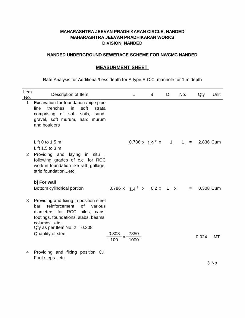
Item No.
Description of Item L B D No. Qty Unit
1 Excavation for foundation /pipe pipeline trenches in soft stratacomprising of soft soils, sand,gravel, soft murum, hard murumand boulders
Lift 0 to 1.5 m 0.786 x 1.9 2 x 1 1 = 2.836 CumLift 1.5 to 3 m
2 Providing and laying in situ ,following grades of c.c. for RCCwork in foundation like raft, grillage,strip foundation...etc.
b] For wallBottom cylindrical portion 0.786 x 1.4 2 x 0.2 x 1 x = 0.308 Cum
3 Providing and fixing in position steelbar reinforcement of variousdiameters for RCC piles, caps,footings, foundations, slabs, beams,columns...etc.Qty as per Item No. 2 = 0.308Quantity of steel 0.308 7850
100 1000
4 Providing and fixing position C.I.Foot steps ..etc.
3 No
MAHARASHTRA JEEVAN PRADHIKARAN CIRCLE, NANDEDMAHARASHTRA JEEVAN PRADHIKARAN WORKS
DIVISION, NANDED
NANDED UNDERGROUND SEWERAGE SCHEME FOR NWCMC NANDED
MEASURMENT SHEET
Rate Analysis for Additional/Less depth for A type R.C.C. manhole for 1 m depth
x 0.024 MT

Item No.
Description of Item L B D No. Qty Unit
1 Excavation for foundation /pipe pipeline trenches in soft stratacomprising of soft soils, sand,gravel, soft murum, hard murumand boulders
a] Lift 0 to 1.5 m 0.786 x 8.6 2 x 1.5 1 = 87.14 Cumb] Lift 1.5 to 3 0.786 x 5.6 2 x 1.5 1 = 36.95 Cumc] Lift 3 to 4.5 0.786 x 1.9 2 x 1.5 1 = 4.25 Cumd] Lift 4.5 to 6 0.786 x 1.9 2 x 1.5 1 = 4.25 Cum
2 Providing and laying in situ ,following grades of c.c. for RCCwork in foundation like raft, grillage,strip foundation...etc. a] For foundation slab 0.786 x 1.9 2 x 0.2 1 = 0.567 Cum
b] For wallBottom cylindrical portion 3.142 x 1.4 x 0.2 x 4.4 x 1 = 3.827 Cum
For Conical portion 3.142 x 0.73 + 1.4 x 0.2 x 1.7 = 1.127 CumAv. Perimeter 2 4.95 Cum
Slant height = 1.684
3 Providing and fixing in position steelbar reinforcement of variousdiameters for RCC piles, caps,footings, foundations, slabs, beams,columns...etc.Qty as per Item No. 2 (a + b) 0.567 + 4.94 = ####
Rate Analysis for B type R.C.C. manhole 1.2 m dia and 6 m deep
MAHARASHTRA JEEVAN PRADHIKARAN CIRCLE, NANDEDMAHARASHTRA JEEVAN PRADHIKARAN WORKS
DIVISION, NANDED
NANDED UNDERGROUND SEWERAGE SCHEME FOR NWCMC NANDED
MEASURMENT SHEET
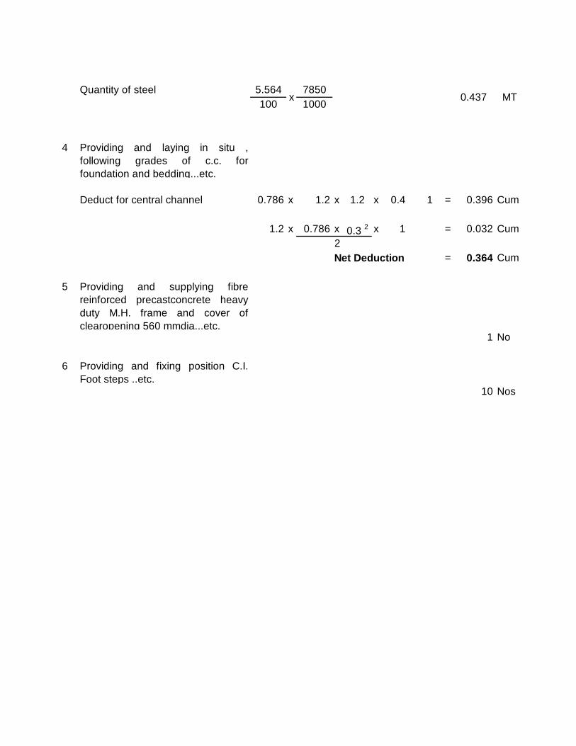
Quantity of steel 5.564 7850100 1000
4 Providing and laying in situ ,following grades of c.c. forfoundation and bedding...etc.
Deduct for central channel 0.786 x 1.2 x 1.2 x 0.4 1 = 0.396 Cum
1.2 x 0.786 x 0.3 2 x 1 = 0.032 Cum2Net Deduction = 0.364 Cum
5 Providing and supplying fibrereinforced precastconcrete heavyduty M.H. frame and cover ofclearopening 560 mmdia...etc.
1 No
6 Providing and fixing position C.I.Foot steps ..etc.
10 Nos
x 0.437 MT
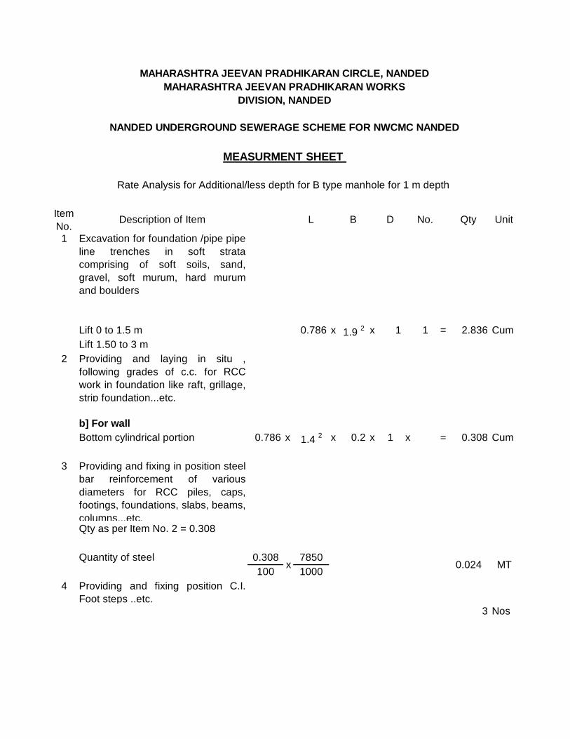
Item No.
Description of Item L B D No. Qty Unit
1 Excavation for foundation /pipe pipeline trenches in soft stratacomprising of soft soils, sand,gravel, soft murum, hard murumand boulders
Lift 0 to 1.5 m 0.786 x 1.9 2 x 1 1 = 2.836 CumLift 1.50 to 3 m
2 Providing and laying in situ ,following grades of c.c. for RCCwork in foundation like raft, grillage,strip foundation...etc.
b] For wallBottom cylindrical portion 0.786 x 1.4 2 x 0.2 x 1 x = 0.308 Cum
3 Providing and fixing in position steelbar reinforcement of variousdiameters for RCC piles, caps,footings, foundations, slabs, beams,columns...etc.Qty as per Item No. 2 = 0.308
Quantity of steel 0.308 7850100 1000
4 Providing and fixing position C.I.Foot steps ..etc.
3 Nos
MEASURMENT SHEET
x 0.024 MT
Rate Analysis for Additional/less depth for B type manhole for 1 m depth
MAHARASHTRA JEEVAN PRADHIKARAN CIRCLE, NANDEDMAHARASHTRA JEEVAN PRADHIKARAN WORKS
DIVISION, NANDED
NANDED UNDERGROUND SEWERAGE SCHEME FOR NWCMC NANDED
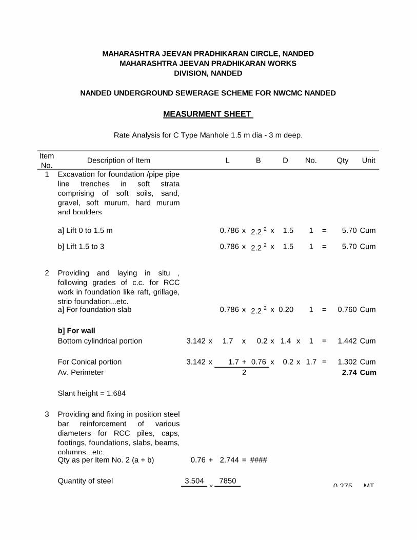
Item No.
Description of Item L B D No. Qty Unit
1 Excavation for foundation /pipe pipeline trenches in soft stratacomprising of soft soils, sand,gravel, soft murum, hard murumand boulders
a] Lift 0 to 1.5 m 0.786 x 2.2 2 x 1.5 1 = 5.70 Cum
b] Lift 1.5 to 3 0.786 x 2.2 2 x 1.5 1 = 5.70 Cum
2 Providing and laying in situ ,following grades of c.c. for RCCwork in foundation like raft, grillage,strip foundation...etc. a] For foundation slab 0.786 x 2.2 2 x 0.20 1 = 0.760 Cum
b] For wallBottom cylindrical portion 3.142 x 1.7 x 0.2 x 1.4 x 1 = 1.442 Cum
For Conical portion 3.142 x 1.7 + 0.76 x 0.2 x 1.7 = 1.302 CumAv. Perimeter 2 2.74 Cum
Slant height = 1.684
3 Providing and fixing in position steelbar reinforcement of variousdiameters for RCC piles, caps,footings, foundations, slabs, beams,columns...etc.Qty as per Item No. 2 (a + b) 0.76 + 2.744 = ####
Quantity of steel 3.504 7850x 0.275 MT
MAHARASHTRA JEEVAN PRADHIKARAN CIRCLE, NANDEDMAHARASHTRA JEEVAN PRADHIKARAN WORKS
DIVISION, NANDED
MEASURMENT SHEET
Rate Analysis for C Type Manhole 1.5 m dia - 3 m deep.
NANDED UNDERGROUND SEWERAGE SCHEME FOR NWCMC NANDED
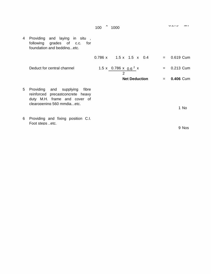
100 1000
4 Providing and laying in situ ,following grades of c.c. forfoundation and bedding...etc.
0.786 x 1.5 x 1.5 x 0.4 = 0.619 Cum
Deduct for central channel 1.5 x 0.786 x 0.6 2 x = 0.213 Cum2Net Deduction = 0.406 Cum
5 Providing and supplying fibrereinforced precastconcrete heavyduty M.H. frame and cover ofclearopening 560 mmdia...etc.
1 No
6 Providing and fixing position C.I.Foot steps ..etc.
9 Nos
x 0.275 MT
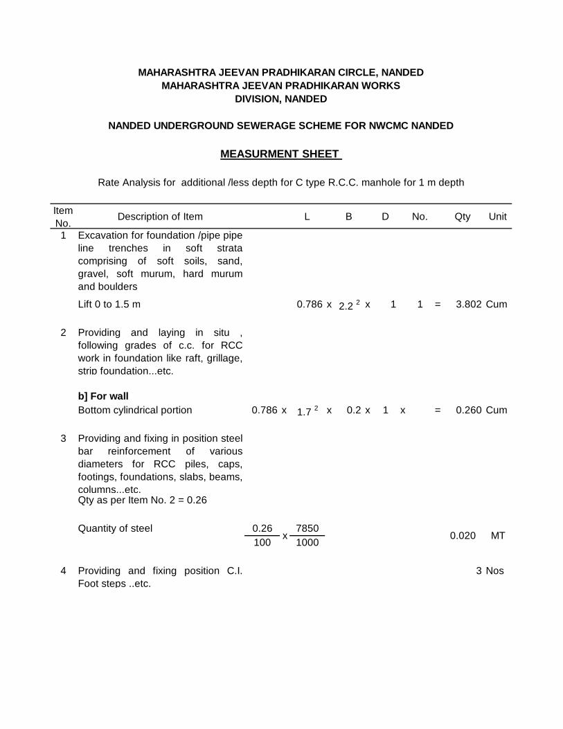
Item No.
Description of Item L B D No. Qty Unit
1 Excavation for foundation /pipe pipeline trenches in soft stratacomprising of soft soils, sand,gravel, soft murum, hard murumand boulders
Lift 0 to 1.5 m 0.786 x 2.2 2 x 1 1 = 3.802 Cum
2 Providing and laying in situ ,following grades of c.c. for RCCwork in foundation like raft, grillage,strip foundation...etc.
b] For wallBottom cylindrical portion 0.786 x 1.7 2 x 0.2 x 1 x = 0.260 Cum
3 Providing and fixing in position steelbar reinforcement of variousdiameters for RCC piles, caps,footings, foundations, slabs, beams,columns...etc.Qty as per Item No. 2 = 0.26
Quantity of steel 0.26 7850100 1000
4 Providing and fixing position C.I.Foot steps ..etc.
3 Nos
MEASURMENT SHEET
x 0.020 MT
Rate Analysis for additional /less depth for C type R.C.C. manhole for 1 m depth
MAHARASHTRA JEEVAN PRADHIKARAN CIRCLE, NANDEDMAHARASHTRA JEEVAN PRADHIKARAN WORKS
DIVISION, NANDED
NANDED UNDERGROUND SEWERAGE SCHEME FOR NWCMC NANDED
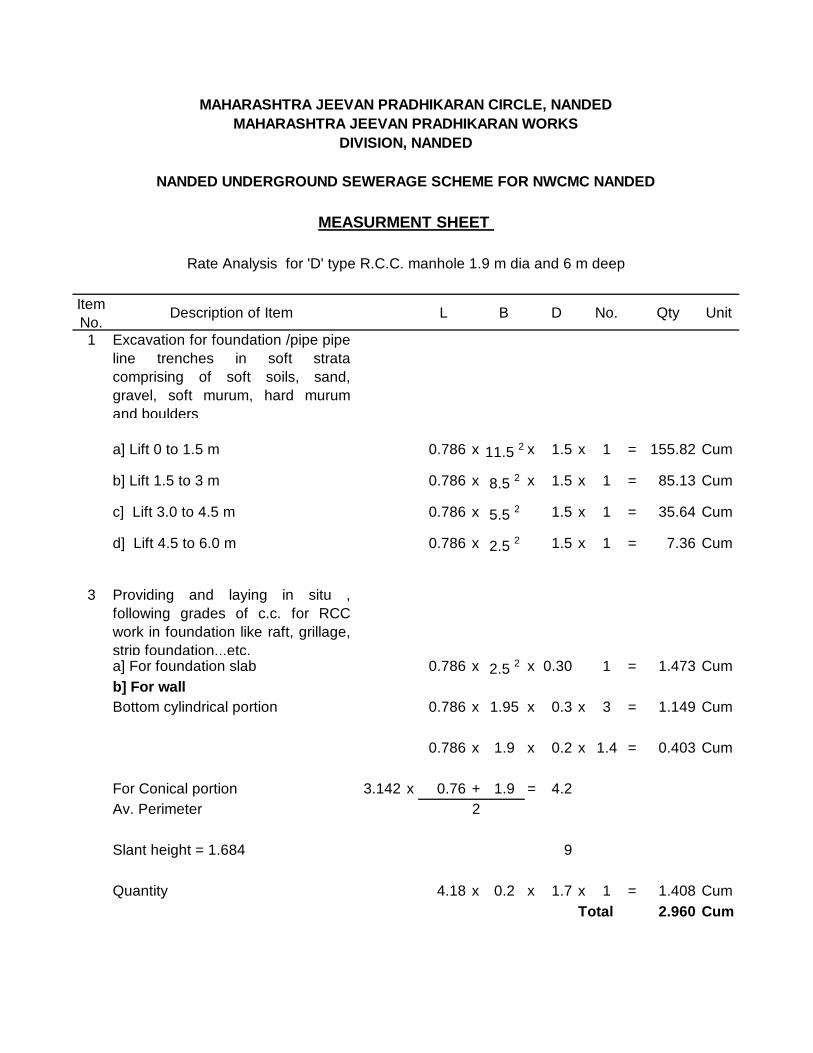
Item No.
Description of Item L B D No. Qty Unit
1 Excavation for foundation /pipe pipeline trenches in soft stratacomprising of soft soils, sand,gravel, soft murum, hard murumand boulders
a] Lift 0 to 1.5 m 0.786 x 11.5 2 x 1.5 x 1 = 155.82 Cum
b] Lift 1.5 to 3 m 0.786 x 8.5 2 x 1.5 x 1 = 85.13 Cum
c] Lift 3.0 to 4.5 m 0.786 x 5.5 2 1.5 x 1 = 35.64 Cum
d] Lift 4.5 to 6.0 m 0.786 x 2.5 2 1.5 x 1 = 7.36 Cum
3 Providing and laying in situ ,following grades of c.c. for RCCwork in foundation like raft, grillage,strip foundation...etc. a] For foundation slab 0.786 x 2.5 2 x 0.30 1 = 1.473 Cumb] For wallBottom cylindrical portion 0.786 x 1.95 x 0.3 x 3 = 1.149 Cum
0.786 x 1.9 x 0.2 x 1.4 = 0.403 Cum
For Conical portion 3.142 x 0.76 + 1.9 = 4.2Av. Perimeter 2
Slant height = 1.684 9
Quantity 4.18 x 0.2 x 1.7 x 1 = 1.408 CumTotal 2.960 Cum
Rate Analysis for 'D' type R.C.C. manhole 1.9 m dia and 6 m deep
NANDED UNDERGROUND SEWERAGE SCHEME FOR NWCMC NANDED
MAHARASHTRA JEEVAN PRADHIKARAN CIRCLE, NANDEDMAHARASHTRA JEEVAN PRADHIKARAN WORKS
DIVISION, NANDED
MEASURMENT SHEET
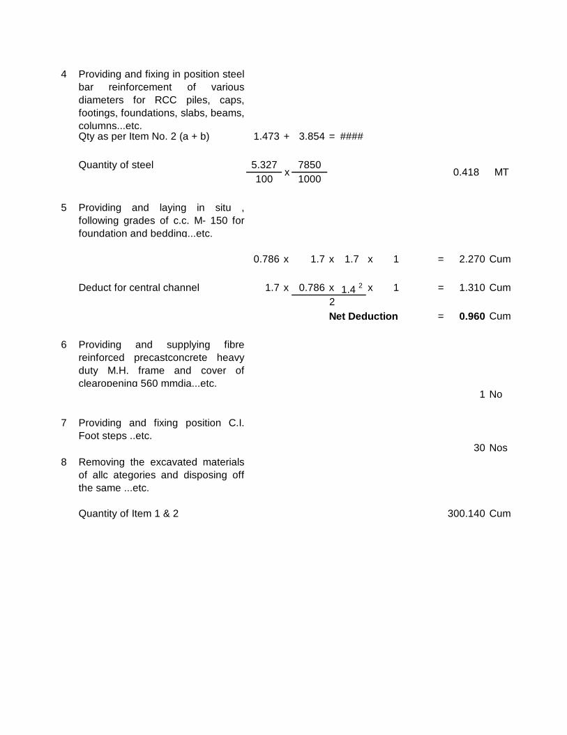
4 Providing and fixing in position steelbar reinforcement of variousdiameters for RCC piles, caps,footings, foundations, slabs, beams,columns...etc.Qty as per Item No. 2 (a + b) 1.473 + 3.854 = ####
Quantity of steel 5.327 7850100 1000
5 Providing and laying in situ ,following grades of c.c. M- 150 forfoundation and bedding...etc.
0.786 x 1.7 x 1.7 x 1 = 2.270 Cum
Deduct for central channel 1.7 x 0.786 x 1.4 2 x 1 = 1.310 Cum2Net Deduction = 0.960 Cum
6 Providing and supplying fibrereinforced precastconcrete heavyduty M.H. frame and cover ofclearopening 560 mmdia...etc.
1 No
7 Providing and fixing position C.I.Foot steps ..etc.
30 Nos 8 Removing the excavated materials
of allc ategories and disposing offthe same ...etc.
Quantity of Item 1 & 2 300.140 Cum
0.418 MTx
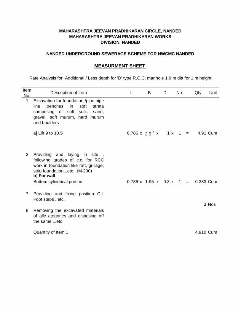
Item No.
Description of Item L B D No. Qty Unit
1 Excavation for foundation /pipe pipeline trenches in soft stratacomprising of soft soils, sand,gravel, soft murum, hard murumand boulders
a] Lift 9 to 10.5 0.786 x 2.5 2 x 1 x 1 = 4.91 Cum
3 Providing and laying in situ ,following grades of c.c. for RCCwork in foundation like raft, grillage,strip foundation...etc. (M-200)b] For wallBottom cylindrical portion 0.786 x 1.95 x 0.3 x 1 = 0.383 Cum
7 Providing and fixing position C.I.Foot steps ..etc.
3 Nos 8 Removing the excavated materials
of allc ategories and disposing offthe same ...etc.
Quantity of Item 1 4.910 Cum
MAHARASHTRA JEEVAN PRADHIKARAN CIRCLE, NANDEDMAHARASHTRA JEEVAN PRADHIKARAN WORKS
DIVISION, NANDED
NANDED UNDERGROUND SEWERAGE SCHEME FOR NWCMC NANDED
MEASURMENT SHEET
Rate Analysis for Additional / Less depth for 'D' type R.C.C. manhole 1.9 m dia for 1 m height

Item No.
Description of Item L B D No. Qty Unit
1 Excavation for foundation /pipe pipeline trenches in soft stratacomprising of soft soils, sand,gravel, soft murum, hard murumand boulders a] Lift 0 to 1.5 mFor horizontal pipe 4.5 x 0.7 x 0.9 x 1 = 2.68 Cum
For pillat 1 x 1 x 0.9 x 1 = 0.90 Cum
3.58 Cum
2 Providing and laying insitu , c.c. forfoundation bedding andencasing...etc. (M-150)
1 x 1 x 0.1 x 1 = 0.10 Cum
3 Providing and fixing in position W.L.soil pipe ...etc.
Horiozontal 5.5Vertical Below G.L.
Bend 0.5Straight 0.6Above 6.0
12.6 12.60 M
4 Providing and fixing in position G.I.mosquito proof spherical meshontop ventilator pipe...etc.
MAHARASHTRA JEEVAN PRADHIKARAN CIRCLE, NANDEDMAHARASHTRA JEEVAN PRADHIKARAN WORKS
DIVISION, NANDED
NANDED UNDERGROUND SEWERAGE SCHEME FOR NWCMC NANDED
Rate Analysis for Sewer Ventilator
MEASURMENT SHEET

1 Nos
5 Providing and laying in situ , M-150forfoundation andbedding andencasing...etc. For Side Walls 0.75 x 0.75 x 1.6 x 1 = 0.87 Cum
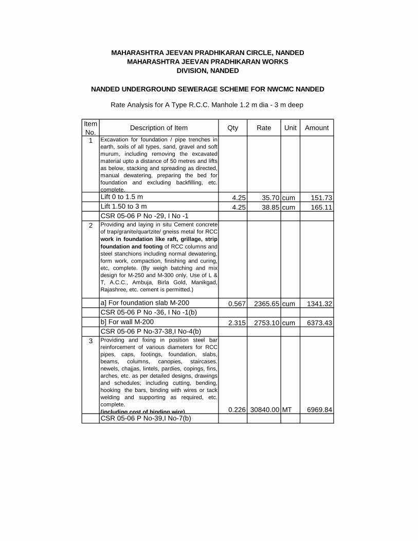
Item No.
Description of Item Qty Rate Unit Amount
1 Excavation for foundation / pipe trenches inearth, soils of all types, sand, gravel and softmurum, including removing the excavatedmaterial upto a distance of 50 metres and liftsas below, stacking and spreading as directed,manual dewatering, preparing the bed forfoundation and excluding backfilling, etc.complete. Lift 0 to 1.5 m 4.25 35.70 cum 151.73Lift 1.50 to 3 m 4.25 38.85 cum 165.11CSR 05-06 P No -29, I No -1
2 Providing and laying in situ Cement concreteof trap/granite/quartzite/ gneiss metal for RCCwork in foundation like raft, grillage, stripfoundation and footing of RCC columns andsteel stanchions including normal dewatering,form work, compaction, finishing and curing,etc, complete. (By weigh batching and mixdesign for M-250 and M-300 only. Use of L &T, A.C.C., Ambuja, Birla Gold, Manikgad,Rajashree, etc. cement is permitted.)
a] For foundation slab M-200 0.567 2365.65 cum 1341.32CSR 05-06 P No -36, I No -1(b)b] For wall M-200 2.315 2753.10 cum 6373.43CSR 05-06 P No-37-38,I No-4(b)
3 Providing and fixing in position steel barreinforcement of various diameters for RCCpipes, caps, footings, foundation, slabs,beams, columns, canopies, staircases.newels, chajjas, lintels, pardies, copings, fins,arches, etc. as per detailed designs, drawingsand schedules; including cutting, bending,hooking the bars, binding with wires or tackwelding and supporting as required, etc.complete. (including cost of binding wire) 0.226 30840.00 MT 6969.84CSR 05-06 P No-39,I No-7(b)
NANDED UNDERGROUND SEWERAGE SCHEME FOR NWCMC NANDED
MAHARASHTRA JEEVAN PRADHIKARAN CIRCLE, NANDEDMAHARASHTRA JEEVAN PRADHIKARAN WORKS
DIVISION, NANDED
Rate Analysis for A Type R.C.C. Manhole 1.2 m dia - 3 m deep

4 Providing and laying in situ Cement concreteof trap/granite/quartzite/ gneiss metal for RCCwork in foundation like raft, grillage, stripfoundation and footing of RCC columns andsteel stanchions including normal dewatering,form work, compaction, finishing and curing,etc, complete. (By weigh batching and mixdesign for M-250 and M-300 only. Use of L &T, A.C.C., Ambuja, Birla Gold, Manikgad,Rajashree, etc. cement is permitted.)
0.354 2211.30 cum 782.80M-150
CSR 05-06 P NO 36 0 I No1(a)
5 Providing and fixing in position steel fibrereinforced concrete (S.F.R.C.) frame andcovers of approved make including loading,unloading, transportation, all taxes, etc.complete as directed by Engineer-in-charge(20 tonnes capacity)560 mm dia 1 1530.00 nos 1530.00CSR 05-06 P NO 233, I No 17(b)
6 Providing and fixing in position C.I. Typedapuri steps of 22 mm dia. M.S. bar step withproper anchorage, etc. and providing andapplying 3 coats of ant-corrosive paint, etccomplete as directed by Engineer-in-charge. 9 99.00 nos 891.00CSR 05-06 P NO 237, I No11 18205.23
18250.00Say Rs.Total Rs.
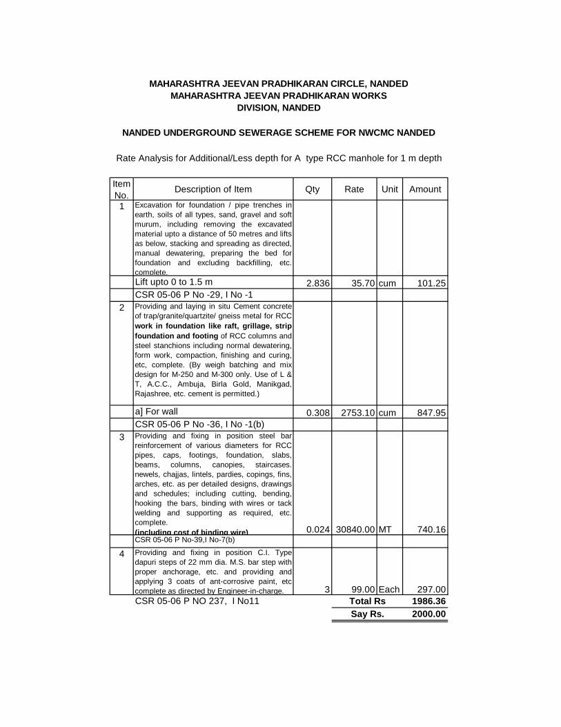
Item No.
Description of Item Qty Rate Unit Amount
1 Excavation for foundation / pipe trenches inearth, soils of all types, sand, gravel and softmurum, including removing the excavatedmaterial upto a distance of 50 metres and liftsas below, stacking and spreading as directed,manual dewatering, preparing the bed forfoundation and excluding backfilling, etc.complete. Lift upto 0 to 1.5 m 2.836 35.70 cum 101.25CSR 05-06 P No -29, I No -1
2 Providing and laying in situ Cement concreteof trap/granite/quartzite/ gneiss metal for RCCwork in foundation like raft, grillage, stripfoundation and footing of RCC columns andsteel stanchions including normal dewatering,form work, compaction, finishing and curing,etc, complete. (By weigh batching and mixdesign for M-250 and M-300 only. Use of L &T, A.C.C., Ambuja, Birla Gold, Manikgad,Rajashree, etc. cement is permitted.)
a] For wall 0.308 2753.10 cum 847.95CSR 05-06 P No -36, I No -1(b)
3 Providing and fixing in position steel barreinforcement of various diameters for RCCpipes, caps, footings, foundation, slabs,beams, columns, canopies, staircases.newels, chajjas, lintels, pardies, copings, fins,arches, etc. as per detailed designs, drawingsand schedules; including cutting, bending,hooking the bars, binding with wires or tackwelding and supporting as required, etc.complete. (including cost of binding wire) 0.024 30840.00 MT 740.16CSR 05-06 P No-39,I No-7(b)
4 Providing and fixing in position C.I. Typedapuri steps of 22 mm dia. M.S. bar step withproper anchorage, etc. and providing andapplying 3 coats of ant-corrosive paint, etccomplete as directed by Engineer-in-charge. 3 99.00 Each 297.00CSR 05-06 P NO 237, I No11 1986.36
2000.00
MAHARASHTRA JEEVAN PRADHIKARAN CIRCLE, NANDEDMAHARASHTRA JEEVAN PRADHIKARAN WORKS
DIVISION, NANDED
NANDED UNDERGROUND SEWERAGE SCHEME FOR NWCMC NANDED
Rate Analysis for Additional/Less depth for A type RCC manhole for 1 m depth
Total RsSay Rs.
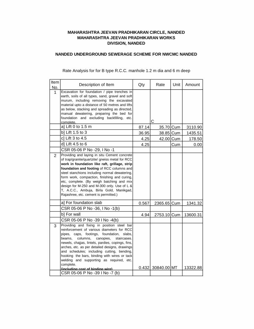
Item No.
Description of Item Qty Rate Unit Amount
1 Excavation for foundation / pipe trenches inearth, soils of all types, sand, gravel and softmurum, including removing the excavatedmaterial upto a distance of 50 metres and liftsas below, stacking and spreading as directed,manual dewatering, preparing the bed forfoundation and excluding backfilling, etc.complete. Ca] Lift 0 to 1.5 m 87.14 35.70 Cum 3110.90b] Lift 1.5 to 3 36.95 38.85 Cum 1435.51c] Lift 3 to 4.5 4.25 42.00 Cum 178.50d] Lift 4.5 to 6 4.25 Cum 0.00CSR 05-06 P No -29, I No -1
2 Providing and laying in situ Cement concreteof trap/granite/quartzite/ gneiss metal for RCCwork in foundation like raft, grillage, stripfoundation and footing of RCC columns andsteel stanchions including normal dewatering,form work, compaction, finishing and curing,etc, complete. (By weigh batching and mixdesign for M-250 and M-300 only. Use of L &T, A.C.C., Ambuja, Birla Gold, Manikgad,Rajashree, etc. cement is permitted.)
a] For foundation slab 0.567 2365.65 Cum 1341.32CSR 05-06 P No -36, I No -1(b)b] For wall 4.94 2753.10 Cum 13600.31CSR 05-06 P No -39 I No -4(b)
3 Providing and fixing in position steel barreinforcement of various diameters for RCCpipes, caps, footings, foundation, slabs,beams, columns, canopies, staircases.newels, chajjas, lintels, pardies, copings, fins,arches, etc. as per detailed designs, drawingsand schedules; including cutting, bending,hooking the bars, binding with wires or tackwelding and supporting as required, etc.complete. (including cost of binding wire) 0.432 30840.00 MT 13322.88CSR 05-06 P No -39 I No -7 (b)
Rate Analysis for for B type R.C.C. manhole 1.2 m dia and 6 m deep
MAHARASHTRA JEEVAN PRADHIKARAN CIRCLE, NANDEDMAHARASHTRA JEEVAN PRADHIKARAN WORKS
DIVISION, NANDED
NANDED UNDERGROUND SEWERAGE SCHEME FOR NWCMC NANDED
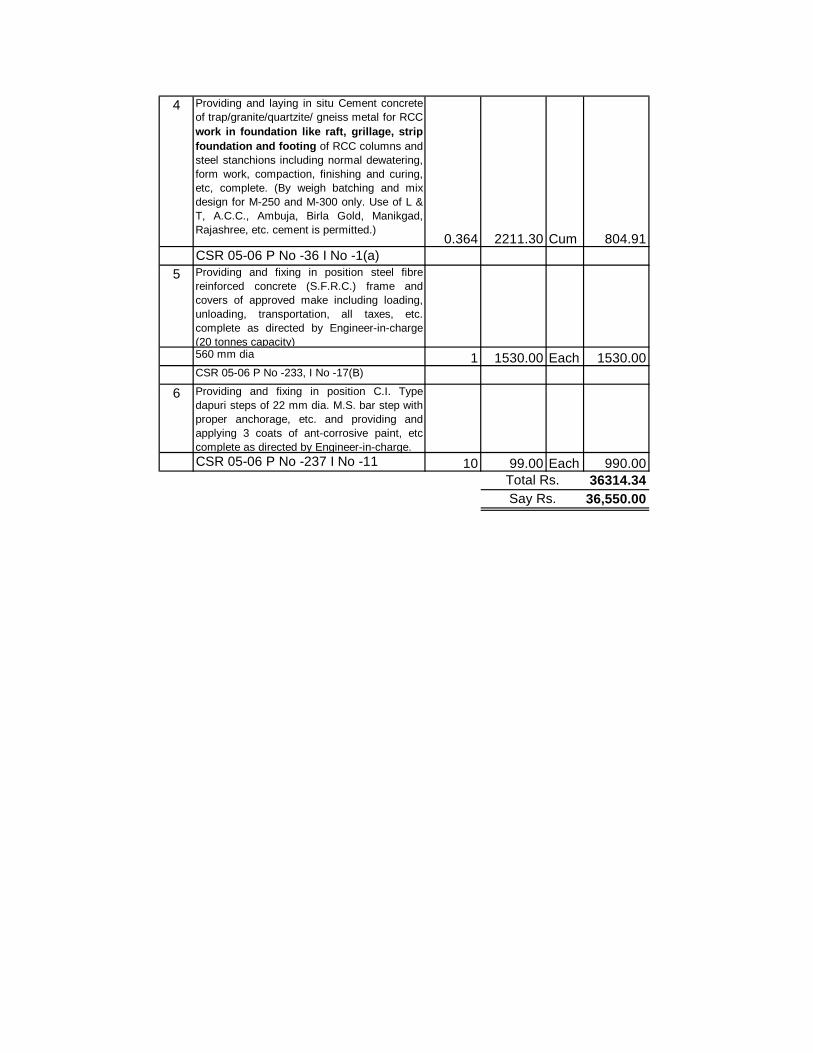
4 Providing and laying in situ Cement concreteof trap/granite/quartzite/ gneiss metal for RCCwork in foundation like raft, grillage, stripfoundation and footing of RCC columns andsteel stanchions including normal dewatering,form work, compaction, finishing and curing,etc, complete. (By weigh batching and mixdesign for M-250 and M-300 only. Use of L &T, A.C.C., Ambuja, Birla Gold, Manikgad,Rajashree, etc. cement is permitted.)
0.364 2211.30 Cum 804.91CSR 05-06 P No -36 I No -1(a)
5 Providing and fixing in position steel fibrereinforced concrete (S.F.R.C.) frame andcovers of approved make including loading,unloading, transportation, all taxes, etc.complete as directed by Engineer-in-charge(20 tonnes capacity)560 mm dia 1 1530.00 Each 1530.00CSR 05-06 P No -233, I No -17(B)
6 Providing and fixing in position C.I. Typedapuri steps of 22 mm dia. M.S. bar step withproper anchorage, etc. and providing andapplying 3 coats of ant-corrosive paint, etccomplete as directed by Engineer-in-charge.CSR 05-06 P No -237 I No -11 10 99.00 Each 990.00
36314.3436,550.00
Total Rs.Say Rs.
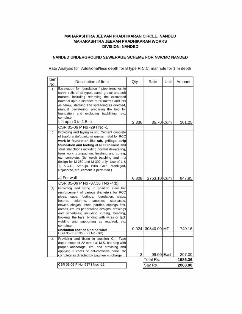
Item No.
Description of Item Qty Rate Unit Amount
1 Excavation for foundation / pipe trenches inearth, soils of all types, sand, gravel and softmurum, including removing the excavatedmaterial upto a distance of 50 metres and liftsas below, stacking and spreading as directed,manual dewatering, preparing the bed forfoundation and excluding backfilling, etc.complete. Lift upto 0 to 1.5 m 2.836 35.70 Cum 101.25CSR 05-06 P No -29 I No -1
2 Providing and laying in situ Cement concreteof trap/granite/quartzite/ gneiss metal for RCCwork in foundation like raft, grillage, stripfoundation and footing of RCC columns andsteel stanchions including normal dewatering,form work, compaction, finishing and curing,etc, complete. (By weigh batching and mixdesign for M-250 and M-300 only. Use of L &T, A.C.C., Ambuja, Birla Gold, Manikgad,Rajashree, etc. cement is permitted.)
a] For wall 0.308 2753.10 Cum 847.95CSR 05-06 P No -37,38 I No -4(b)
3 Providing and fixing in position steel barreinforcement of various diameters for RCCpipes, caps, footings, foundation, slabs,beams, columns, canopies, staircases.newels, chajjas, lintels, pardies, copings, fins,arches, etc. as per detailed designs, drawingsand schedules; including cutting, bending,hooking the bars, binding with wires or tackwelding and supporting as required, etc.complete. (including cost of binding wire) 0.024 30840.00 MT 740.16CSR 05-06 P No -39 I No -7(b)
4 Providing and fixing in position C.I. Typedapuri steps of 22 mm dia. M.S. bar step withproper anchorage, etc. and providing andapplying 3 coats of ant-corrosive paint, etccomplete as directed by Engineer-in-charge. 3 99.00 Each 297.00
Total Rs. 1986.36CSR 05-06 P No -237 I Noc -11 Say Rs. 2000.00
MAHARASHTRA JEEVAN PRADHIKARAN CIRCLE, NANDEDMAHARASHTRA JEEVAN PRADHIKARAN WORKS
DIVISION, NANDED
Rate Analysis for Additional/less depth for B type R.C.C. manhole for 1 m depth
NANDED UNDERGROUND SEWERAGE SCHEME FOR NWCMC NANDED
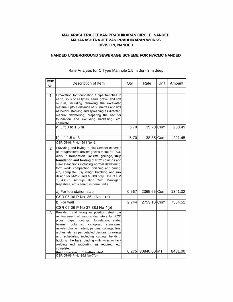
Item No.
Description of Item Qty Rate Unit Amount
1 Excavation for foundation / pipe trenches inearth, soils of all types, sand, gravel and softmurum, including removing the excavatedmaterial upto a distance of 50 metres and liftsas below, stacking and spreading as directed,manual dewatering, preparing the bed forfoundation and excluding backfilling, etc.complete. a] Lift 0 to 1.5 m 5.70 35.70 Cum 203.49 b] Lift 1.5 to 3 5.70 38.85 Cum 221.45CSR 05-06 P No -29 I No -1
2 Providing and laying in situ Cement concreteof trap/granite/quartzite/ gneiss metal for RCCwork in foundation like raft, grillage, stripfoundation and footing of RCC columns andsteel stanchions including normal dewatering,form work, compaction, finishing and curing,etc, complete. (By weigh batching and mixdesign for M-250 and M-300 only. Use of L &T, A.C.C., Ambuja, Birla Gold, Manikgad,Rajashree, etc. cement is permitted.)
a] For foundation slab 0.567 2365.65 Cum 1341.32CSR 05-06 P No -36, I No -1(b)b] For wall 2.744 2753.10 Cum 7554.51CSR 05-06 P No-37-38,I No-4(b)
3 Providing and fixing in position steel barreinforcement of various diameters for RCCpipes, caps, footings, foundation, slabs,beams, columns, canopies, staircases.newels, chajjas, lintels, pardies, copings, fins,arches, etc. as per detailed designs, drawingsand schedules; including cutting, bending,hooking the bars, binding with wires or tackwelding and supporting as required, etc.complete. (including cost of binding wire) 0.275 30840.00 MT 8481.00CSR 05-06 P No-39,I No-7(b)
Rate Analysis for C Type Manhole 1.5 m dia - 3 m deep
MAHARASHTRA JEEVAN PRADHIKARAN CIRCLE, NANDEDMAHARASHTRA JEEVAN PRADHIKARAN WORKS
DIVISION, NANDED
NANDED UNDERGROUND SEWERAGE SCHEME FOR NWCMC NANDED

4 Providing and laying in situ Cement concreteof trap/granite/quartzite/ gneiss metal for RCCwork in foundation like raft, grillage, stripfoundation and footing of RCC columns andsteel stanchions including normal dewatering,form work, compaction, finishing and curing,etc, complete. (By weigh batching and mixdesign for M-250 and M-300 only. Use of L &T, A.C.C., Ambuja, Birla Gold, Manikgad,Rajashree, etc. cement is permitted.)
0.408 2211.30 Cum 902.21CSR 05-06 P No -237 I Noc -11
5 Providing and fixing in position steel fibrereinforced concrete (S.F.R.C.) frame andcovers of approved make including loading,unloading, transportation, all taxes, etc.complete as directed by Engineer-in-charge(20 tonnes capacity)560 mm dia 1 2382.00 Each 2382.00CSR 05-06 P NO 233, I No 17(b)
6 Providing and fixing in position C.I. Typedapuri steps of 22 mm dia. M.S. bar step withproper anchorage, etc. and providing andapplying 3 coats of ant-corrosive paint, etccomplete as directed by Engineer-in-charge. 9 99.00 Each 891.00CSR 05-06 P NO 237, I No11 Total Rs. 21976.98
Say Rs. 22000.00

Item No.
Description of Item Qty Rate Unit Amount
1 Excavation for foundation / pipe trenches inearth, soils of all types, sand, gravel and softmurum, including removing the excavatedmaterial upto a distance of 50 metres and liftsas below, stacking and spreading as directed,manual dewatering, preparing the bed forfoundation and excluding backfilling, etc.complete. Lift upto 0 to 1.5 m 3.802 35.70 Cum 135.73CSR 05-06 P No -29 I No -1
2 Providing and laying in situ Cement concreteof trap/granite/quartzite/ gneiss metal for RCCwork in foundation like raft, grillage, stripfoundation and footing of RCC columns andsteel stanchions including normal dewatering,form work, compaction, finishing and curing,etc, complete. (By weigh batching and mixdesign for M-250 and M-300 only. Use of L &T, A.C.C., Ambuja, Birla Gold, Manikgad,Rajashree, etc. cement is permitted.)
a] For wall 0.26 2753.10 Cum 715.81CSR 05-06 P No-37-38,I No-4(b)
3 Providing and fixing in position steel barreinforcement of various diameters for RCCpipes, caps, footings, foundation, slabs,beams, columns, canopies, staircases.newels, chajjas, lintels, pardies, copings, fins,arches, etc. as per detailed designs, drawingsand schedules; including cutting, bending,hooking the bars, binding with wires or tackwelding and supporting as required, etc.complete. (including cost of binding wire) 0.02 30840.00 MT 616.80CSR 05-06 P No-39,I No-7(b)
4 Providing and fixing in position C.I. Typedapuri steps of 22 mm dia. M.S. bar step withproper anchorage, etc. and providing andapplying 3 coats of ant-corrosive paint, etccomplete as directed by Engineer-in-charge. 3 99.00 Each 297.00CSR 05-06 P NO 237, I No11 Total Rs. 1765.34
Say Rs. 1800.00
NANDED UNDERGROUND SEWERAGE SCHEME FOR NWCMC NANDED
Rate Analysis for additional /less depth for C type manhole for 1 m depth
MAHARASHTRA JEEVAN PRADHIKARAN CIRCLE, NANDEDMAHARASHTRA JEEVAN PRADHIKARAN WORKS
DIVISION, NANDED
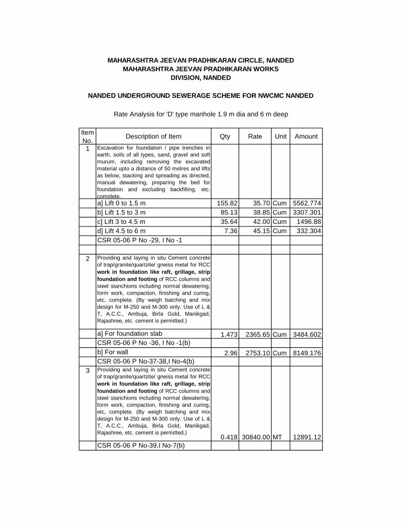
Item No.
Description of Item Qty Rate Unit Amount
1 Excavation for foundation / pipe trenches inearth, soils of all types, sand, gravel and softmurum, including removing the excavatedmaterial upto a distance of 50 metres and liftsas below, stacking and spreading as directed,manual dewatering, preparing the bed forfoundation and excluding backfilling, etc.complete. a] Lift 0 to 1.5 m 155.82 35.70 Cum 5562.774b] Lift 1.5 to 3 m 85.13 38.85 Cum 3307.301c] Lift 3 to 4.5 m 35.64 42.00 Cum 1496.88d] Lift 4.5 to 6 m 7.36 45.15 Cum 332.304CSR 05-06 P No -29, I No -1
2 Providing and laying in situ Cement concreteof trap/granite/quartzite/ gneiss metal for RCCwork in foundation like raft, grillage, stripfoundation and footing of RCC columns andsteel stanchions including normal dewatering,form work, compaction, finishing and curing,etc, complete. (By weigh batching and mixdesign for M-250 and M-300 only. Use of L &T, A.C.C., Ambuja, Birla Gold, Manikgad,Rajashree, etc. cement is permitted.)
a] For foundation slab 1.473 2365.65 Cum 3484.602CSR 05-06 P No -36, I No -1(b)b] For wall 2.96 2753.10 Cum 8149.176CSR 05-06 P No-37-38,I No-4(b)
3 Providing and laying in situ Cement concreteof trap/granite/quartzite/ gneiss metal for RCCwork in foundation like raft, grillage, stripfoundation and footing of RCC columns andsteel stanchions including normal dewatering,form work, compaction, finishing and curing,etc, complete. (By weigh batching and mixdesign for M-250 and M-300 only. Use of L &T, A.C.C., Ambuja, Birla Gold, Manikgad,Rajashree, etc. cement is permitted.)
0.418 30840.00 MT 12891.12CSR 05-06 P No-39,I No-7(b)
NANDED UNDERGROUND SEWERAGE SCHEME FOR NWCMC NANDED
Rate Analysis for 'D' type manhole 1.9 m dia and 6 m deep
MAHARASHTRA JEEVAN PRADHIKARAN CIRCLE, NANDEDMAHARASHTRA JEEVAN PRADHIKARAN WORKS
DIVISION, NANDED

4 Providing and laying in situ Cement concreteof trap/granite/quartzite/ gneiss metal for RCCwork in foundation like raft, grillage, stripfoundation and footing of RCC columns andsteel stanchions including normal dewatering,form work, compaction, finishing and curing,etc, complete. (By weigh batching and mixdesign for M-250 and M-300 only. Use of L &T, A.C.C., Ambuja, Birla Gold, Manikgad,Rajashree, etc. cement is permitted.)
0.96 2211.30 Cum 2122.848CSR 05-06 P NO 36 0 I No1(a)
5 Providing and fixing in position steel fibrereinforced concrete (S.F.R.C.) frame andcovers of approved make including loading,unloading, transportation, all taxes, etc.complete as directed by Engineer-in-charge(20 tonnes capacity)560 mm dia 1 1530.00 Each 1530CSR 05-06 P NO 233, I No 17(b)
6 Providing and fixing in position C.I. Typedapuri steps of 22 mm dia. M.S. bar step withproper anchorage, etc. and providing andapplying 3 coats of ant-corrosive paint, etccomplete as directed by Engineer-in-charge. 30 99.00 Each 2970CSR 05-06 P NO 237, I No11
7 Removing the excavated materials of allcategories and disposing off the same upto 10km including loading, unloading, trasportationand stacking...etc. as directed to Engineer In-charge 300.14 32.76 Cum 9832.586CSR 05-06 P. No 20 Statement E 51679.59
51700.00Total RsSay Rs.
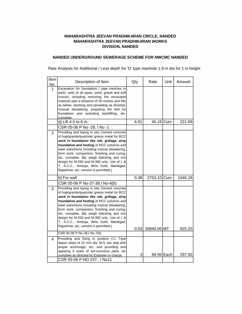
Rate Analysis for Additional / Less depth for 'D' type manhole 1.9 m dia for 1 m height
Item No.
Description of Item Qty Rate Unit Amount
1 Excavation for foundation / pipe trenches inearth, soils of all types, sand, gravel and softmurum, including removing the excavatedmaterial upto a distance of 50 metres and liftsas below, stacking and spreading as directed,manual dewatering, preparing the bed forfoundation and excluding backfilling, etc.complete. a] Lift 4.5 to 6 m 4.91 45.15 Cum 221.69CSR 05-06 P No -29, I No -1
2 Providing and laying in situ Cement concreteof trap/granite/quartzite/ gneiss metal for RCCwork in foundation like raft, grillage, stripfoundation and footing of RCC columns andsteel stanchions including normal dewatering,form work, compaction, finishing and curing,etc, complete. (By weigh batching and mixdesign for M-250 and M-300 only. Use of L &T, A.C.C., Ambuja, Birla Gold, Manikgad,Rajashree, etc. cement is permitted.)
b] For wall 0.38 2753.10 Cum 1046.18CSR 05-06 P No-37-38,I No-4(b)
3 Providing and laying in situ Cement concreteof trap/granite/quartzite/ gneiss metal for RCCwork in foundation like raft, grillage, stripfoundation and footing of RCC columns andsteel stanchions including normal dewatering,form work, compaction, finishing and curing,etc, complete. (By weigh batching and mixdesign for M-250 and M-300 only. Use of L &T, A.C.C., Ambuja, Birla Gold, Manikgad,Rajashree, etc. cement is permitted.)
0.03 30840.00 MT 925.20CSR 05-06 P No-39,I No-7(b)
4 Providing and fixing in position C.I. Typedapuri steps of 22 mm dia. M.S. bar step withproper anchorage, etc. and providing andapplying 3 coats of ant-corrosive paint, etccomplete as directed by Engineer-in-charge. 3 99.00 Each 297.00CSR 05-06 P NO 237, I No11
NANDED UNDERGROUND SEWERAGE SCHEME FOR NWCMC NANDED
MAHARASHTRA JEEVAN PRADHIKARAN CIRCLE, NANDEDMAHARASHTRA JEEVAN PRADHIKARAN WORKS
DIVISION, NANDED

5 Removing the excavated materials of allcategories and disposing off the same upto 10km including loading, unloading, trasportationand stacking...etc. as directed to Engineer In-charge 4.91 32.76 Cum 160.85CSR 05-06 P. No 20 Statement E 2650.92
2700.00Total Rs.Say Rs.
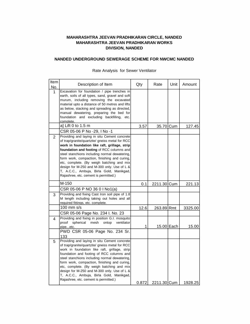
Item No.
Description of Item Qty Rate Unit Amount
1 Excavation for foundation / pipe trenches inearth, soils of all types, sand, gravel and softmurum, including removing the excavatedmaterial upto a distance of 50 metres and liftsas below, stacking and spreading as directed,manual dewatering, preparing the bed forfoundation and excluding backfilling, etc.complete. a] Lift 0 to 1.5 m 3.57 35.70 Cum 127.45CSR 05-06 P No -29, I No -1
2 Providing and laying in situ Cement concreteof trap/granite/quartzite/ gneiss metal for RCCwork in foundation like raft, grillage, stripfoundation and footing of RCC columns andsteel stanchions including normal dewatering,form work, compaction, finishing and curing,etc, complete. (By weigh batching and mixdesign for M-250 and M-300 only. Use of L &T, A.C.C., Ambuja, Birla Gold, Manikgad,Rajashree, etc. cement is permitted.)
M-150 0.1 2211.30 Cum 221.13CSR 05-06 P NO 36 0 I No1(a)
3 Providing and fixing Cast Iron soil pipe of 1.8M length including taking out holes and allrequired fittings, etc. complete.100 mm s/s 12.6 263.89 Rmt 3325.00CSR 05-06 Page No. 234 I. No. 23
4 Providing and fixing in position G.I. mosquitoproof spherical mesh ontop ventilatorpipe...etc. 1 15.00 Each 15.00PWD CSR 05-06 Page No. 234 Sr.133
5 Providing and laying in situ Cement concreteof trap/granite/quartzite/ gneiss metal for RCCwork in foundation like raft, grillage, stripfoundation and footing of RCC columns andsteel stanchions including normal dewatering,form work, compaction, finishing and curing,etc, complete. (By weigh batching and mixdesign for M-250 and M-300 only. Use of L &T, A.C.C., Ambuja, Birla Gold, Manikgad,Rajashree, etc. cement is permitted.)
0.872 2211.30 Cum 1928.25
Rate Analysis for Sewer Ventilator
NANDED UNDERGROUND SEWERAGE SCHEME FOR NWCMC NANDED
MAHARASHTRA JEEVAN PRADHIKARAN CIRCLE, NANDEDMAHARASHTRA JEEVAN PRADHIKARAN WORKS
DIVISION, NANDED

CSR 05-06 P NO 36 0 I No1(a) 5616.835600.00
Total Rs.Say Rs.