Embed Size (px)
Citation preview
July 2009 10636
ZITHOLELE CONSULTING
8
33 DDEETTAAIILLEEDD DDEESSCCRRIIPPTTIIOONN OOFF TTHHEE PPRROOPPOOSSEEDD AACCTTIIVVIITTYY
3.1 Project Description and Infrastructure
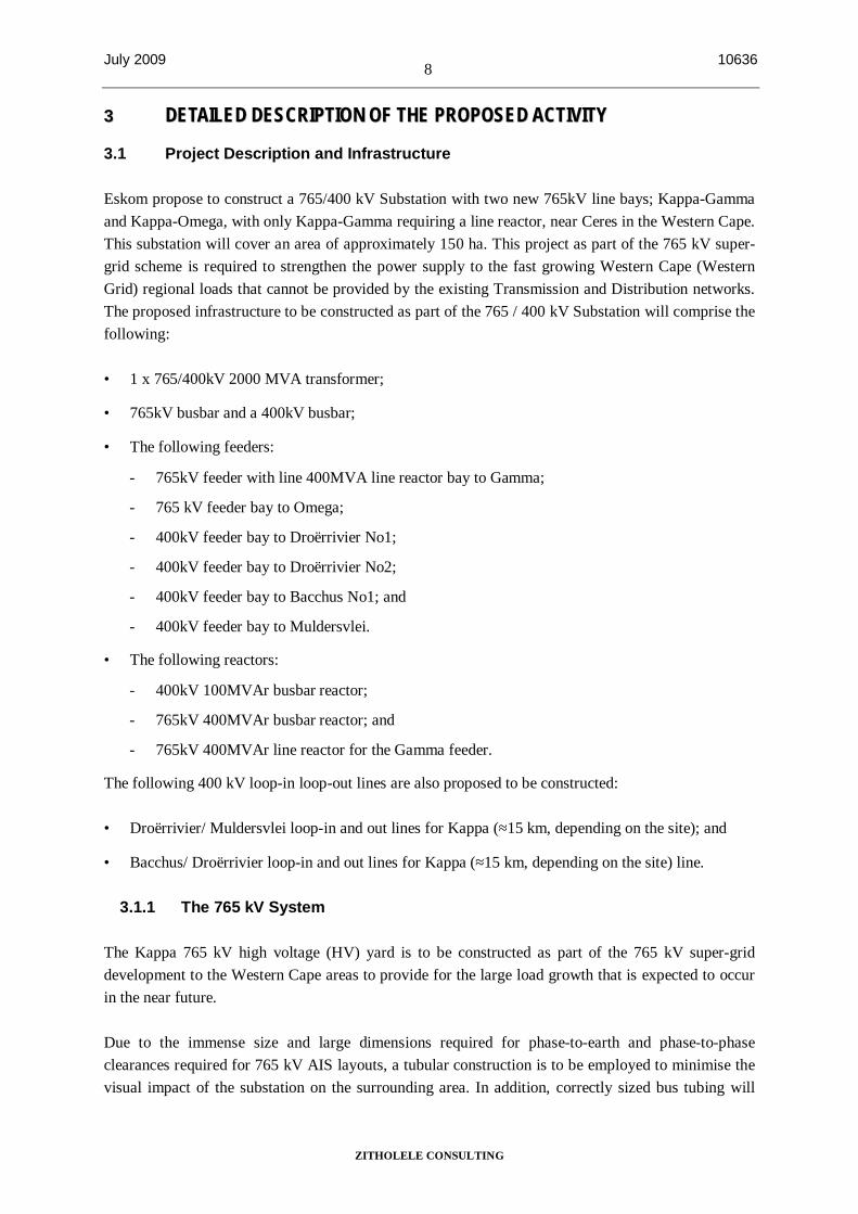
Eskom propose to construct a 765/400 kV Substation with two new 765kV line bays; Kappa-Gamma and Kappa-Omega, with only Kappa-Gamma requiring a line reactor, near Ceres in the Western Cape. This substation will cover an area of approximately 150 ha. This project as part of the 765 kV super-grid scheme is required to strengthen the power supply to the fast growing Western Cape (Western Grid) regional loads that cannot be provided by the existing Transmission and Distribution networks. The proposed infrastructure to be constructed as part of the 765 / 400 kV Substation will comprise the following:
• 1 x 765/400kV 2000 MVA transformer;
• 765kV busbar and a 400kV busbar;
• The following feeders:
- 765kV feeder with line 400MVA line reactor bay to Gamma;
- 765 kV feeder bay to Omega;
- 400kV feeder bay to Droërrivier No1;
- 400kV feeder bay to Droërrivier No2;
- 400kV feeder bay to Bacchus No1; and
- 400kV feeder bay to Muldersvlei.
• The following reactors:
- 400kV 100MVAr busbar reactor;
- 765kV 400MVAr busbar reactor; and
- 765kV 400MVAr line reactor for the Gamma feeder.
The following 400 kV loop-in loop-out lines are also proposed to be constructed:
• Droërrivier/ Muldersvlei loop-in and out lines for Kappa (≈15 km, depending on the site); and
• Bacchus/ Droërrivier loop-in and out lines for Kappa (≈15 km, depending on the site) line.
3.1.1 The 765 kV System
The Kappa 765 kV high voltage (HV) yard is to be constructed as part of the 765 kV super-grid development to the Western Cape areas to provide for the large load growth that is expected to occur in the near future.
Due to the immense size and large dimensions required for phase-to-earth and phase-to-phase clearances required for 765 kV AIS layouts, a tubular construction is to be employed to minimise the visual impact of the substation on the surrounding area. In addition, correctly sized bus tubing will
July 2009 9 10636
ZITHOLELE CONSULTING
minimise the corona discharge at these ultra-high voltages. It is also necessary to cater for the level of injected and through power the busbar system will be required to support once the Medupi and other power station projects are completed.
The 765 kV busbar configuration is to depart from the conventional double busbar selection with bypass, in favour of a more reliable “One-and-a-half Circuit Breaker” philosophy, with an added benefit in that the length of the busbar is reduced to less than half that of its counterpart. The system still employs two normal running busbars (No.1 and No.2), but with a three circuit breaker system servicing two circuits. This arrangement eliminates the need for the bypass facility due to the sharing of the so called “Tie” circuit breaker that allows automatic re-routing of power flow under live conditions if a busbar fault occurs. The arrangement inherently provides for access to all circuit breakers, which is not the case with the current double busbar selection with bypass. The possible future expansion of the Kappa 765 kV system also provides for two bus sections to facilitate the removal of smaller zones of busbar for maintenance purposes.
In order to minimise the initial work required to establish the first phase of the 765 kV system at Kappa, future Feeder 4 Reactor position is to be used for Busbar Reactor 1.
The section of the Reactor Transfer Busbar servicing the above bays is to be constructed with the connections to it. The rational behind this is that it will be difficult of retrofitting it later due to limited outages that are granted and the large electromagnetic fields that are involved when working in the HV yard.
The 765kV Kappa system will be comprised of the following bays:-
• 2 x fully equipped feeder bays tied back-to-back with the appropriate circuits through a “Tie” circuit breaker bay to provide for the 1½ circuit breaker arrangement (Gamma 1 and Omega 1);
• 1 x fully equipped switch-able line reactor bay tied back-to-back with the appropriate circuits through a “Tie” circuit breaker bay to provide for the 1½ circuit breaker arrangement (Gamma 1);
• 1 x fully equipped switch-able busbar reactor bay tied back-to-back with the appropriate circuits through a “Tie” circuit breaker bay to provide for the 1½ circuit breaker arrangement (Busbar Reactor 1);
• 1 x fully equipped transformer bay tied back-to-back with the appropriate circuits through a “Tie” circuit breaker bay to provide for the 1½ circuit breaker arrangement (T1); and
• 2 x partially equipped bus section bays with a set of CVT’s and an isolator each (No.1 Bus Section 1 and No.2 Bus Section 1).
3.1.2 The 400 kV System
The 400 kV yard will be built with tubular busbars in order to minimise the visual impact of the substation on the surrounding area as well as to coup with the amount of injected and through power the busbar systems will be required to support in the future.
July 2009 10 10636
ZITHOLELE CONSULTING
As with the 765 kV busbar configuration, the 400kV busbar system is to depart from the conventional double busbar selection with bypass, in favour of a more reliable “One-and-a-half Circuit Breaker” philosophy. The system still employs two normal running busbars (No.1 and No.2), but with a three circuit breaker system servicing two circuits. This arrangement eliminates the need for the bypass facility due to the sharing of the so called “Tie” circuit breaker that allows automatic re-routing of power flow under live conditions if a busbar fault occurs. The arrangement inherently provides for access to all circuit breakers, which is not the case with the current double busbar selection with bypass. The possible future expansion of the Kappa 400kV system also provides for two bus sections to facilitate the removal of smaller zones of busbar for maintenance purposes. However, depending on the growth of the 400kV network, it is possible to have a staggered bus section arrangement to further improve on flexibility and security of supply, to cater for double zone outages.
The 400kV Kappa system will be comprised of the following bays:-
• 4 x fully equipped feeder bays tied back-to-back with the appropriate circuits through a “Tie” circuit breaker bay to provide for the 1½ circuit breaker arrangement (Droërrivier 1, Droërrivier 2, Bacchus 1 and Muldersvlei 1);
• 1 x fully equipped transformer bay tied back-to-back with the appropriate circuit through a “Tie” circuit breaker bay to provide for the 1½ circuit breaker arrangement (Transformer 1);
• 1 x fully equipped switch-able busbar reactor bay tied back-to-back with the appropriate circuits through a “Tie” circuit breaker bay to provide for the 1½ circuit breaker arrangement (Busbar Reactor 11); and
• 2 x partially equipped bus sections with a set of CVT’s bays and isolator with busbar earth-switches each (No.1 Bus Section 1 and No.2 Bus Section 1).
3.2 Infrastructure
3.2.1 Description of a Substation
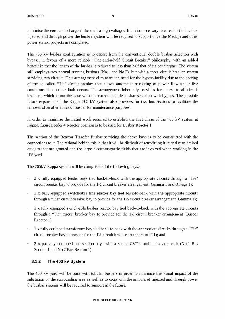
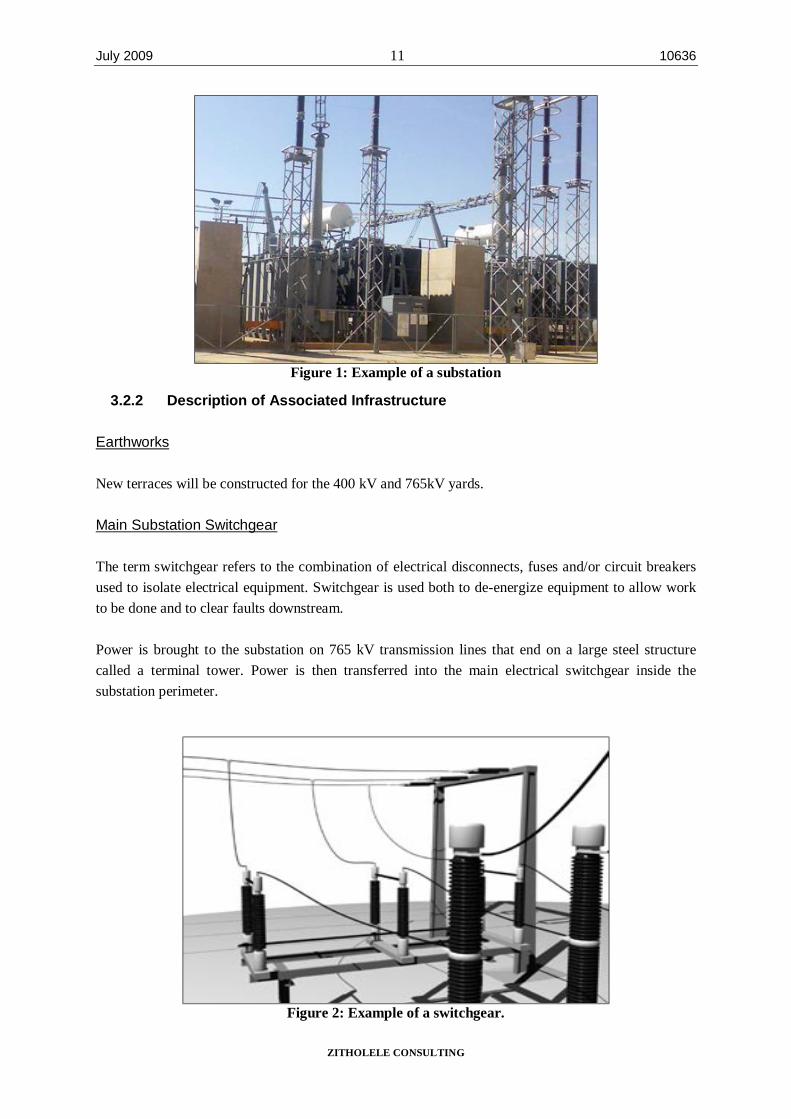
The proposed substation will act as a switching station for the existing transmission lines in the Ceres area. The fact that the substation will need to act as a switching station for several existing power lines means that it needs to be situated near the convergence of these lines. Figure 1 and Figure 3 below provide an example of what a substation looks like and the proposed layout of the substation respectively.
July 2009 11 10636
ZITHOLELE CONSULTING
Figure 1: Example of a substation
3.2.2 Description of Associated Infrastructure
Earthworks
New terraces will be constructed for the 400 kV and 765kV yards.
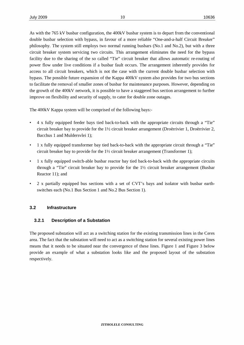
Main Substation Switchgear
The term switchgear refers to the combination of electrical disconnects, fuses and/or circuit breakers used to isolate electrical equipment. Switchgear is used both to de-energize equipment to allow work to be done and to clear faults downstream.
Power is brought to the substation on 765 kV transmission lines that end on a large steel structure called a terminal tower. Power is then transferred into the main electrical switchgear inside the substation perimeter.
Figure 2: Example of a switchgear.
July 2009 10636
ZITHOLELE CONSULTING
12
Figure 3: Proposed Substation Site Layout.
July 2009 10636
ZITHOLELE CONSULTING
13
Foundations, plinths and trenches
Main column, tubular bus, equipment foundations for the 765 kV system , 1 x 2000MVA, 765/400kV transformer plinth (3 x single phase units), 3 x 400MVAr, 765kV reactor plinths (3 x single phase units per line reactor), and cable trenches in the 765kV yard must be provided.
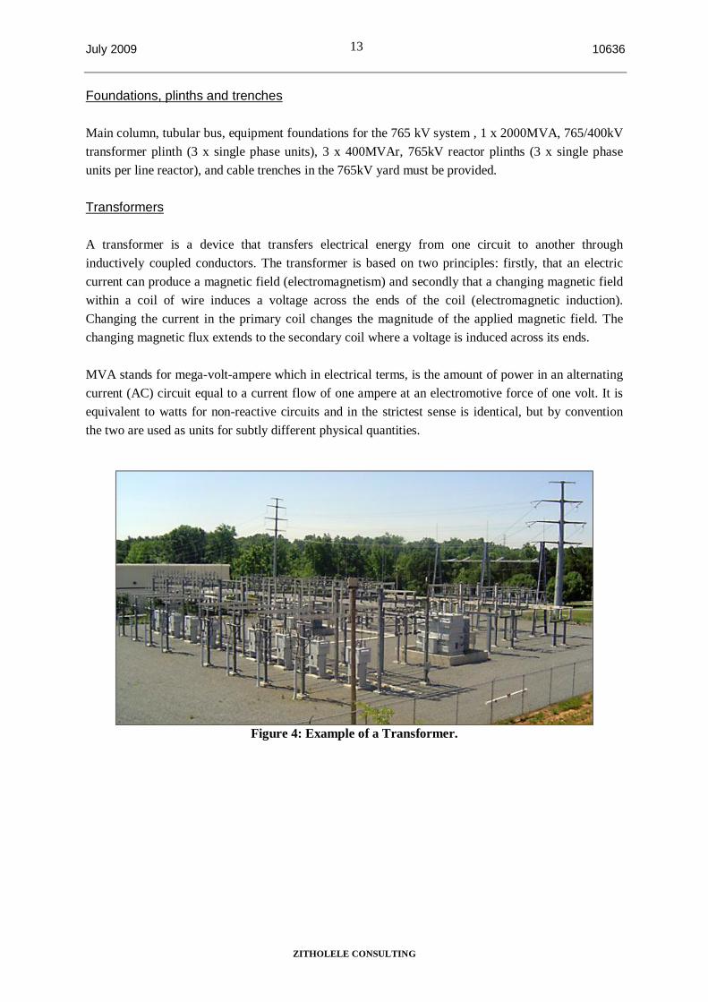
Transformers
A transformer is a device that transfers electrical energy from one circuit to another through inductively coupled conductors. The transformer is based on two principles: firstly, that an electric current can produce a magnetic field (electromagnetism) and secondly that a changing magnetic field within a coil of wire induces a voltage across the ends of the coil (electromagnetic induction). Changing the current in the primary coil changes the magnitude of the applied magnetic field. The changing magnetic flux extends to the secondary coil where a voltage is induced across its ends.
MVA stands for mega-volt-ampere which in electrical terms, is the amount of power in an alternating current (AC) circuit equal to a current flow of one ampere at an electromotive force of one volt. It is equivalent to watts for non-reactive circuits and in the strictest sense is identical, but by convention the two are used as units for subtly different physical quantities.
Figure 4: Example of a Transformer.
July 2009 14 10636
ZITHOLELE CONSULTING
Figure 5: Example of a Pollution Control Facility (Oil holding dam).
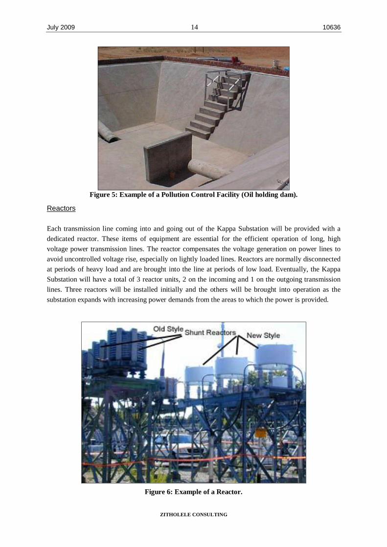
Reactors
Each transmission line coming into and going out of the Kappa Substation will be provided with a dedicated reactor. These items of equipment are essential for the efficient operation of long, high voltage power transmission lines. The reactor compensates the voltage generation on power lines to avoid uncontrolled voltage rise, especially on lightly loaded lines. Reactors are normally disconnected at periods of heavy load and are brought into the line at periods of low load. Eventually, the Kappa Substation will have a total of 3 reactor units, 2 on the incoming and 1 on the outgoing transmission lines. Three reactors will be installed initially and the others will be brought into operation as the substation expands with increasing power demands from the areas to which the power is provided.
Figure 6: Example of a Reactor.
July 2009 15 10636
ZITHOLELE CONSULTING
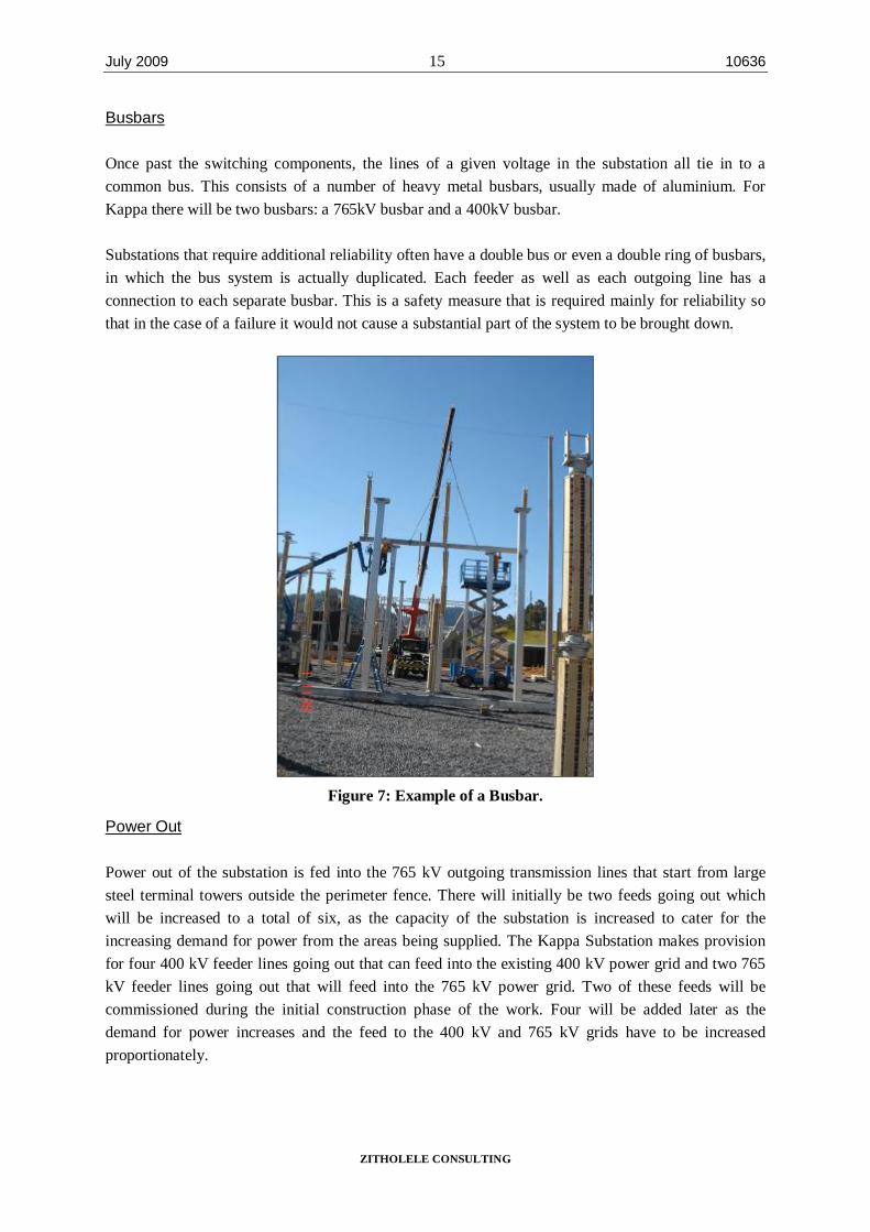
Busbars
Once past the switching components, the lines of a given voltage in the substation all tie in to a common bus. This consists of a number of heavy metal busbars, usually made of aluminium. For Kappa there will be two busbars: a 765kV busbar and a 400kV busbar.
Substations that require additional reliability often have a double bus or even a double ring of busbars, in which the bus system is actually duplicated. Each feeder as well as each outgoing line has a connection to each separate busbar. This is a safety measure that is required mainly for reliability so that in the case of a failure it would not cause a substantial part of the system to be brought down.
Figure 7: Example of a Busbar.
Power Out
Power out of the substation is fed into the 765 kV outgoing transmission lines that start from large steel terminal towers outside the perimeter fence. There will initially be two feeds going out which will be increased to a total of six, as the capacity of the substation is increased to cater for the increasing demand for power from the areas being supplied. The Kappa Substation makes provision for four 400 kV feeder lines going out that can feed into the existing 400 kV power grid and two 765 kV feeder lines going out that will feed into the 765 kV power grid. Two of these feeds will be commissioned during the initial construction phase of the work. Four will be added later as the demand for power increases and the feed to the 400 kV and 765 kV grids have to be increased proportionately.
July 2009 16 10636
ZITHOLELE CONSULTING
Buildings
When operational, the substation is not manned on a 24-hour basis. Extensive buildings and service facilities are, therefore, not needed. The main facilities to be provided include a small office, workshop areas and storage space, external storage areas, battery room and a control room to house the high voltage monitoring and control instrumentation and equipment. The substation will also be equipped with Eskom’s own internal micro-wave telecommunications facilities.
Fencing
The double barrier security fence is to be installed to encompass the whole of the new 400kV and 765kV yards, and provide with a new safety fence around the 765kV yards that is to be constructed under this project.
Roads
A new tarred access road to the substation, system of 6m substation concrete roads, and a system of 3m concrete 765kV yard roads are required.
Drainage
Storm water, oil drainage systems and an oil holding dam are required.
Telecommunication Masts
A telecommunication mast will be required at the Kappa Substation. The mast will be a microwave lattice mast, between 30 and 50 m high and will form an integral part of the substation.
3.3 Construction Phase
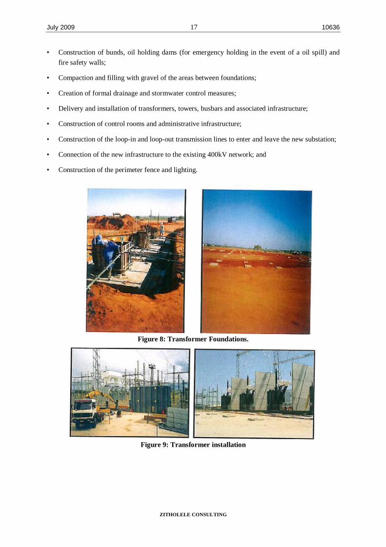
The construction phase for the substation will take 3 years and will include the construction of access roads to the substation, which will remain once construction is finished as part of the substation’s permanent infrastructure. The civil construction works i.e. roads, platforming, stormwater control and foundations is likely to take place for a period of 12 months, with the balance of time taken up with the fabrication and erection of steelwork. The various stages of the construction phase are shown in the photographs below. The construction phase will entail the following:
• Construction of access roads to the substation;
• Removal of vegetation within the substation footprint;
• Terracing and levelling of the site;
• Installation of foundations for infrastructure such as transformers, control building and radio tower;
July 2009 17 10636
ZITHOLELE CONSULTING
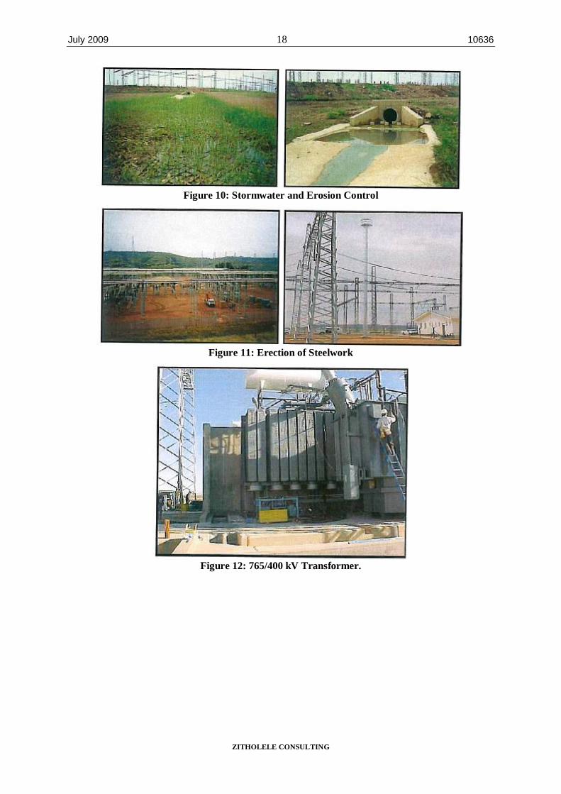
• Construction of bunds, oil holding dams (for emergency holding in the event of a oil spill) and fire safety walls;
• Compaction and filling with gravel of the areas between foundations;
• Creation of formal drainage and stormwater control measures;
• Delivery and installation of transformers, towers, busbars and associated infrastructure;
• Construction of control rooms and administrative infrastructure;
• Construction of the loop-in and loop-out transmission lines to enter and leave the new substation;
• Connection of the new infrastructure to the existing 400kV network; and
• Construction of the perimeter fence and lighting.
Figure 8: Transformer Foundations.
Figure 9: Transformer installation
July 2009 18 10636
ZITHOLELE CONSULTING
Figure 10: Stormwater and Erosion Control
Figure 11: Erection of Steelwork
Figure 12: 765/400 kV Transformer.
July 2009 19 10636
ZITHOLELE CONSULTING
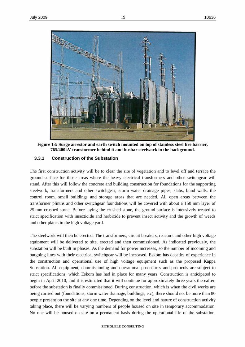
Figure 13: Surge arrestor and earth switch mounted on top of stainless steel fire barrier,
765/400kV transformer behind it and busbar steelwork in the background.
3.3.1 Construction of the Substation
The first construction activity will be to clear the site of vegetation and to level off and terrace the ground surface for those areas where the heavy electrical transformers and other switchgear will stand. After this will follow the concrete and building construction for foundations for the supporting steelwork, transformers and other switchgear, storm water drainage pipes, slabs, bund walls, the control room, small buildings and storage areas that are needed. All open areas between the transformer plinths and other switchgear foundations will be covered with about a 150 mm layer of 25 mm crushed stone. Before laying the crushed stone, the ground surface is intensively treated to strict specification with insecticide and herbicide to prevent insect activity and the growth of weeds and other plants in the high voltage yard.
The steelwork will then be erected. The transformers, circuit breakers, reactors and other high voltage equipment will be delivered to site, erected and then commissioned. As indicated previously, the substation will be built in phases. As the demand for power increases, so the number of incoming and outgoing lines with their electrical switchgear will be increased. Eskom has decades of experience in the construction and operational use of high voltage equipment such as the proposed Kappa Substation. All equipment, commissioning and operational procedures and protocols are subject to strict specifications, which Eskom has had in place for many years. Construction is anticipated to begin in April 2010, and it is estimated that it will continue for approximately three years thereafter, before the substation is finally commissioned. During construction, which is when the civil works are being carried out (foundations, storm water drainage, buildings, etc), there should not be more than 80 people present on the site at any one time. Depending on the level and nature of construction activity taking place, there will be varying numbers of people housed on site in temporary accommodation. No one will be housed on site on a permanent basis during the operational life of the substation.
July 2009 20 10636
ZITHOLELE CONSULTING
However, there will be ongoing monitoring and control of operations as well as planned and other maintenance work done on an ad hoc basis.
3.3.2 Temporary Storage of Hazardous Substances
The hazardous substances referred to comprise fuels, oils and lubricants that will be stored and dispensed at the construction camp. Specifications for the storage and dispensing of fuels, oils and lubricants include the following:
• Specifically designated areas.
• All storage of fuels, oils and lubricants shall be stored above ground and under cover.
• All designated areas will be bunded.
• Each designated area will be equipped with adequate fire protection equipment appropriate for the nature of the fuels, oils and lubricants that are stored and dispensed.
• All areas shall be properly signed in all applicable languages.
• All employees must be properly trained in the storage and dispensing of specific fuels, oils and lubricants.
• A specific procedure for emergency situations, including accidental spills, will be formulated and available on site at all times.
3.3.3 Use of Services during Construction
Water
Water will be required for potable use and in the construction of the foundations for the substation. The water will be sourced from a borehole on site.
Sewerage
A negligible sewerage flow is anticipated for the duration of the construction period. On site, use will be made of chemical toilets that will be serviced periodically. For operations, a similarly negligible amount of sewerage will be generated. Septic tanks and soak aways will be provided.
Roads
Existing roads will be utilised as far as possible during the construction and operational periods. The use of roads on private property is subject to the provisions of an EMP that will include individual landowner specifications, which will be determined during discussions with landowners during the land acquisition negotiation process. The Kappa Substation will be served by a gravel access road and internal gravelled traffic areas for access to the Extra High Voltage (EHV) equipment. The flow of traffic to the site during the construction period will be relatively light and during operations there will be virtually no traffic.
July 2009 21 10636
ZITHOLELE CONSULTING
Stormwater
Soil on site is clayey and sandy (derived from sandstone and shale parent rock in the Karoo geological system) and sensitive to water and wind erosion. Although the mean annual rainfall is relatively low, the area does experience short, sharp or intensive thunderstorm type precipitation. Great care has to be taken in making sure that storm water drainage is carefully designed on all roads as well as the runoff from the substation terraces. Storm water will have to be diverted into the veld at low energy levels to make sure that significant erosion problems are avoided in and around the site.
Storm water will be managed according to the Eskom Guidelines for Erosion Control and Vegetation Management as well as the provisions of the EMP.
Solid Waste
All solid waste will be collected at a central location at the construction site and will be stored temporarily until removal to an appropriately permitted landfill site. Waste streams should be kept separate to facilitate recycling.
Electricity
Either Eskom Distribution will provide electricity for construction or diesel generators will be utilized for the provision of electricity. For operations, electricity will be sourced from Eskom Distribution.
Economics and job creation
The proposed Kappa Substation will cost approximately R 850 million to construct.
At the busiest time of the construction work, which is when the civil works are being carried out (foundations, storm water drainage, buildings, etc), there should not be more than 80 people present on the site at any one time. Depending on the level and nature of construction activity taking place, there will be varying numbers of people housed on site in temporary accommodation. Employment will be effected either directly with the main contractor or through sub-contractors, which will include Small and Medium Enterprises (SMEs) and Affirmative Business Enterprises (ABEs).
It is important to note that the construction of a substation is a specialised undertaking requiring skilled people. It is probable that the appointed contractors will bring in skilled staff from other areas. By implication, job opportunities for local people will be limited to unskilled jobs, on site and in construction camps. Apart from direct employment, local people and businesses will benefit through the supply of goods and services to the appointed contractors.
Environmental Management Plan
A project-specific EMP has been compiled for the project. An Environmental Control Officer (ECO), who acts as an intermediary between individual landowners, Eskom and the contractors, will monitor compliance with the EMP.
July 2009 22 10636
ZITHOLELE CONSULTING
3.4 Operation and Maintenance Phase
During operations, Eskom requires access to the substation for maintenance activities. This will require traversing private property. Maintenance activities are specialised and are, therefore, carried out by Eskom employees.
During the operational life of the substation, there will be no people housed on site on a permanent basis.
3.5 Decommissioning Phase
The following are assumed:
• The physical removal of the substation infrastructure would entail the reversal of the construction process.
• A rehabilitation programme would need to be agreed upon with the landowners before being implemented.
• The disposal of materials from the decommissioned substation would be at an approved waste disposal facility. Alternatively, recycling opportunities could be investigated and implemented.
All of the afore-mentioned would be subject to a separate EIA and environmental authorisation at the appropriate time.