Embed Size (px)
Citation preview
METU Department of Computer Engineering
Detailed Design Report SNMP Agent & Network Simulator
Osman Tahsin Berktaş M. Elgin Akpınar
Mustafa İlhan
26.12.2010
Sponsored by “Siemens EC”
SNMP Agent & Network Simulator Cennet Elması
2
Index 1. Introduction ....................................................................................................................................4
1.1. Problem Definition ...................................................................................................................4
1.2. Purpose ....................................................................................................................................4
1.3. Scope .......................................................................................................................................4
1.4. Overview ..................................................................................................................................5
1.5. Definitions, Acronyms and Abbreviations .................................................................................5
1.6. References ...............................................................................................................................5
2. System Overview ............................................................................................................................6
3. Design Considerations .....................................................................................................................7
3.1. Design Assumptions, Dependencies and Constraints ....................................................................7
3.1.1 Assumptions and Dependencies .........................................................................................7
3.1.2 Constraints .........................................................................................................................7
3.2. Design Goals and Guidelines .....................................................................................................8
4. Data Design .....................................................................................................................................9
4.1. Data Description.......................................................................................................................9
4.2. Data Dictionary ...................................................................................................................... 10
5. System Architecture ...................................................................................................................... 15
5.1. Architectural Design ............................................................................................................... 15
5.2.1. HTML Renderer Component ............................................................................................ 15
5.2.2. Simulation Engine Component ......................................................................................... 16
5.2.3. SNMP Component ........................................................................................................... 17
5.2.4. Persistence Component ................................................................................................... 18
5.3. Design Rationale .................................................................................................................... 20
6. User Interface Design .................................................................................................................... 21
6.1. Overview of User Interface ..................................................................................................... 21
6.2. Screen Images ........................................................................................................................ 22
6.3. Screen Objects and Actions .................................................................................................... 25
7. Detailed Design ...................................................................................................................... 27
7.1 HTML Renderer Component ................................................................................................ 27
7.2 Persistence Component ....................................................................................................... 28
7.3 Simulation Engine Component............................................................................................. 28
7.4 SNMP Component ............................................................................................................... 29

SNMP Agent & Network Simulator Cennet Elması
3
8. Libraries and Tools ........................................................................................................................ 31
8.1 Google Web Toolkit (GWT) ...................................................................................................... 31
8.2 jSNMP ..................................................................................................................................... 31
8.3 Google App Engine .................................................................................................................. 31
8.4 Google Code ............................................................................................................................ 31
8.5 Eclipse Plug-in ......................................................................................................................... 31
8.6 SAX XML Parser ....................................................................................................................... 31
8.7 Mibble MIB Parser ................................................................................................................... 32
9. Time Planning ............................................................................................................................... 33
9.1 Term 1 Gannt Chart ................................................................................................................. 33
9.2 Term 2 Gannt Chart ................................................................................................................. 35
10. Conclusion .................................................................................................................................. 36
SNMP Agent & Network Simulator Cennet Elması
4
1. Introduction
This document is prepared to give the detailed design patterns of the SNMP Agent & Network Simulator project which is sponsored by Siemens EC and is prepared by Group Cennet Elması whose members are the senior students in Computer Engineering
Department of Middle East Technical University.
1.1. Problem Definition
There are three main problems related with the network management:
First of all, real networks are so difficult to instantiate (purchase, install, and
configure) for experiments with scenarios, especially for large network configurations. Moreover, it is hard to create desired network conditions in real networks for controlled experiments, e.g., with network traffic loads and congestion patterns of interest.
Second one is that often, new network protocols are proposed, such as new
Transmission Control Protocol (TCP) variants or new multi-cast protocols. The designers of the protocols not only need to analyze the protocols’ strengths and weaknesses but also need to convince themselves and the others that the proposed protocols would work as well as, or better than other existing protocols before venturing into developing real deployments. Similarly, new networking hardware capabilities (such as faster links or interconnections) need to be tested in configurations of interest.
Finally, in certain situations, simulation is useful for re-creating scenarios in order to
verify certain theories/models or to better understand certain phenomena. For example, simulation is useful to reconstruct Internet worm attacks in simulation in order to learn more about their operation and their sensitivities to network topology and traffic conditions. Since it is not possible to re-enact such malicious traffic on a real network, network simulation serves as a software-based duplicate of existing networks.
1.2. Purpose
The purpose of this report is to explain the detailed design steps to the programmer who wants to understand how the software system will be structured to satisfy the requirements. This report is the primary reference for code development and, therefore, it contains all the information required by a programmer to write code.
1.3. Scope
The scope of this document includes the detailed design patterns of SNMP Agent & Network Simulation project, brief explanation about the goal, objectives and benefits of the project, constraints, assumptions, dependencies, detailed data description and data dictionary, system architecture with its components, user interface and actions of objects, libraries and tools that will be used. The audience of this document comprises the programmers who develop SNMP Agent & Network Simulators.

SNMP Agent & Network Simulator Cennet Elması
5
1.4. Overview
The content of this document includes the detailed design of the SNMP Agent & Network Simulator project. Project goals are listed in section 3. Data descriptions and main classes which will be used in implementation is described and explained definite in section 4. In section 5, our projects’ architecture is illustrated by diagrams. Section 6 includes some examples of the user interfaces. Detailed description is explained in section 7. Used libraries and tools are explained in section 8. Our time schedule is showed in section 9 by using Gantt chart.
1.5. Definitions, Acronyms and Abbreviations
GWT: Google Web Toolkit MIB (Management Information Base): Database of the objects that the agent
tracks. SNMP: Set of operations which give the administrators the ability to change the
properties and state of some SNMP-based devices. SNMP Agent: A piece of software that runs on the network devices being managed
by SNMP Simulator. Trap: A code or signal designed to capture errors and reveal where they are
1.6. References
[1] Google Web Toolkit Home Page, http://code.google.com/intl/tr-TR/webtoolkit/
[2] jSNMP Enterprises Home Page, http://www.jsnmp.com/products.html [3] Google App Engine Home Page, http://code.google.com/intl/tr-TR/appengine/ [4] Google Project Hosting, http://code.google.com/intl/tr-TR/projecthosting/ [5] Google Plugin for Eclipse, http://code.google.com/intl/tr-TR/eclipse/ [6] SAX parser, http://sax.sourceforge.net/ [7] MIB Parser http://www.mibble.org/ [8] wikipedia SNMP, “Simple Network Management Protocol” http://en.wikipedia.org/wiki/Simple_Network_Management_Protocol

SNMP Agent & Network Simulator Cennet Elması
6
2. System Overview
As represented in the figure 1, today's companies have so many computers and other IP devices. SNMP Agent and Network Simulator create virtual network environment and devices. Therefore, using this system, multiple devices can be tested and this system requires no installation since it is a web-based application and user can be accessed it by using any browser.
This projects’ goal is to construct abstract devices and to see the behavior of them in
the network system. The benefits of our project is getting rid of bulky hardware devices which are instantiated in the testing laboratories, saving the time, constructing the desired testing environment and reducing the cost and time of the testing process.
Figure 1: Product Overview

SNMP Agent & Network Simulator Cennet Elması
7
3. Design Considerations
In this section special design issues are covered. Design assumptions, dependencies, constraints, our goal and some guidelines are stated in following sections.
3.1. Design Assumptions, Dependencies and
Constraints
3.1.1 Assumptions and Dependencies
The system will be built in using these protocols: SNMP v1 (version 1) and SNMP v2 (version 2). All system will be built on this limitation. Since the software will run on the server, users’ computer performance will not excessively affect the software performance. However tested number of devices in the system is a essential manner and affects the performance of the simulation. Therefore the number of devices for testing is limited to 20.000 devices at the same simulation. Actually this number depends on the power of server but this is enough for the project and sponsored company. In addition to these NodeTypes in the system should have different MIB file name to prevent conflicts so the file names must be different.
3.1.2 Constraints
3.1.2.1 Time Constraints
This project is a senior student project, given by the department of Computer Engineering. So the schedule and timing is determined and strict. After this report there will be a certain deadline for a final decision report and a prototype must be presented by mid-January, 2010. The implementation should be fully done by June, 2010.
3.1.2.2 Safety and Security Constraints
For the safety, system will check the scenario whether there is a mismatch or not. In other words the result of simulation is checked that given values is appropriate for the run scenario. For the security, there will be a login screen to enter the system, since the system will be only used by the owner company. Other accesses are not allowed to use the system.
3.1.2.3 Hardware Constraints
Hardware Requirements for Developer: Intel Core 2 Duo 2 GHz processor 2 GB Ram 256 MB Graphic Card 50 GB HDD Space Internet connection
Hardware Requirements for Server: Intel Core 2 Duo 2.24 GHz processor 4 GB Ram 256 MB Graphic Card 40 GB HDD Space

SNMP Agent & Network Simulator Cennet Elması
8
Fast Internet connection (minimum 1Mpbs) Hardware Requirements for User:
Celeron 1.6GHz processor 512 MB Ram 256 MB Graphic Card Internet connection
3.1.2.4 Software Constraints
Software requirements are in 3 groups: developer, server and the user. Software Requirements for Developer:
Windows XP / Vista / 7, MacOS or Linux distribution Google Web Toolkit Google App Engine Eclipse Web-browser Java SDK and JRE
Software Requirements for Server: Google App Engine
Software Requirements for the user: Web-browser
3.2. Design Goals and Guidelines
Design of the system is dominated by SNMP which gives the name of the project. The design of the software depends mostly on functionalities of these protocols. And also implementing the software is eased by the power of the Google Web Toolkit. Detailed explanation about the tools, which will be used, is given in section 7. One of the main goals in this report is to give definite picture of the software. The aims of this project are:
To simulate a network that consists of more than 20.000 devices. To implement SNMP Simulation. To design a better interface. To design web-based software so usability will be better.
To design a user friendly software by using simple drag and drop buttons.

SNMP Agent & Network Simulator Cennet Elması
9
4. Data Design
4.1. Data Description
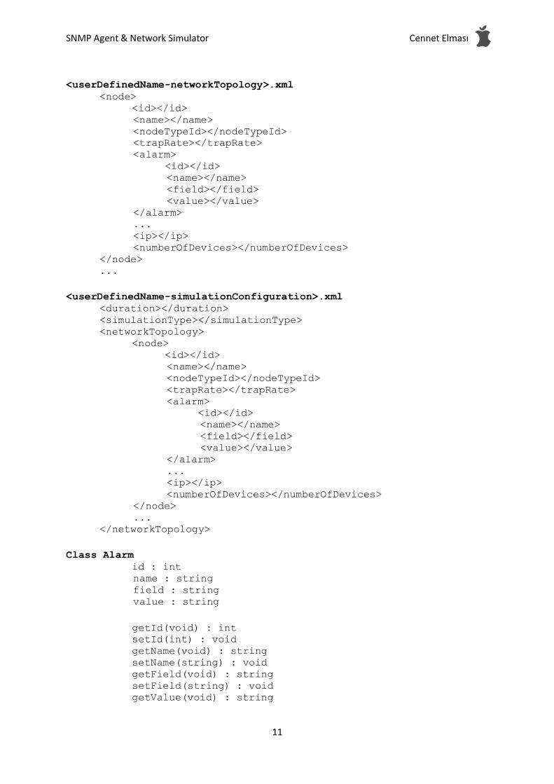
This section describes data objects that will be used and managed in SMNP Agent Simulator in terms of how they are stored, processed and organized. 4.1.1 nodeTypes.xml: This XML file stores node types (device types) in the system. When
system is booted, this file is parsed and NodeTypes object is created. Moreover, all changes made by the user affect this file and it is updated. 4.1.2 <userDefinedName-networkTopology>.xml: This XML file stores Network Topology created by the user. Attributes of the current NetworkTopology object are written to the file which is kept in “NetworkTopologies” directory and it can be loaded later. 4.1.3 <userDefinedName-simulationConfiguration>.xml: It stores current simulation confi-
guration generated by the user. This file is kept under “SimulationConfigurations” directory and can be loaded to system later. 4.1.4 NodeType: This data object is used to hold the values of the IP devices in the system. It is used for creating network topology, in other words, nodes in the network topology are selected from these objects. New type can be added or existing ones can be edited or deleted. In the configuration behavior of the system this data corresponds to an object of a list which is NodeTypes. However in the run or simulation behavior of the system this data are disabled. This data object is generated temporarily. 4.1.5 NodeTypes: This data is a list of all NodeType objects in the system and generated when html page rendered after nodeTypes.xml file is parsed. It is not stored, dynamically created. 4.1.6 Alarm: Alarm data is generated from MIB of a NodeType object.
4.1.7 MIB: When a NodeType is selected its MIB is parsed and generated this object. All
alarms of MIB are stored in this object and when a new node type is selected it is created dynamically. 4.1.8 Node: It is an object that represents a node in the network topology and generated when a NodeType is selected.
4.1.9 NetworkTopology: This data is a list of Node objects of the current network topology. All created new Nodes are added to this list and generated during the Node objects are created. This list can be saved to a XML file and can be loaded from a XML file. 4.1.10 Simulation: All properties to run the simulation are attributes of this data. It can be
saved to XML file and can be loaded from XML file. 4.1.11 SimulationType: It is an enumeration to decide simulation mode. This mode may be
real time mode or reduced mode.
SNMP Agent & Network Simulator Cennet Elması
10
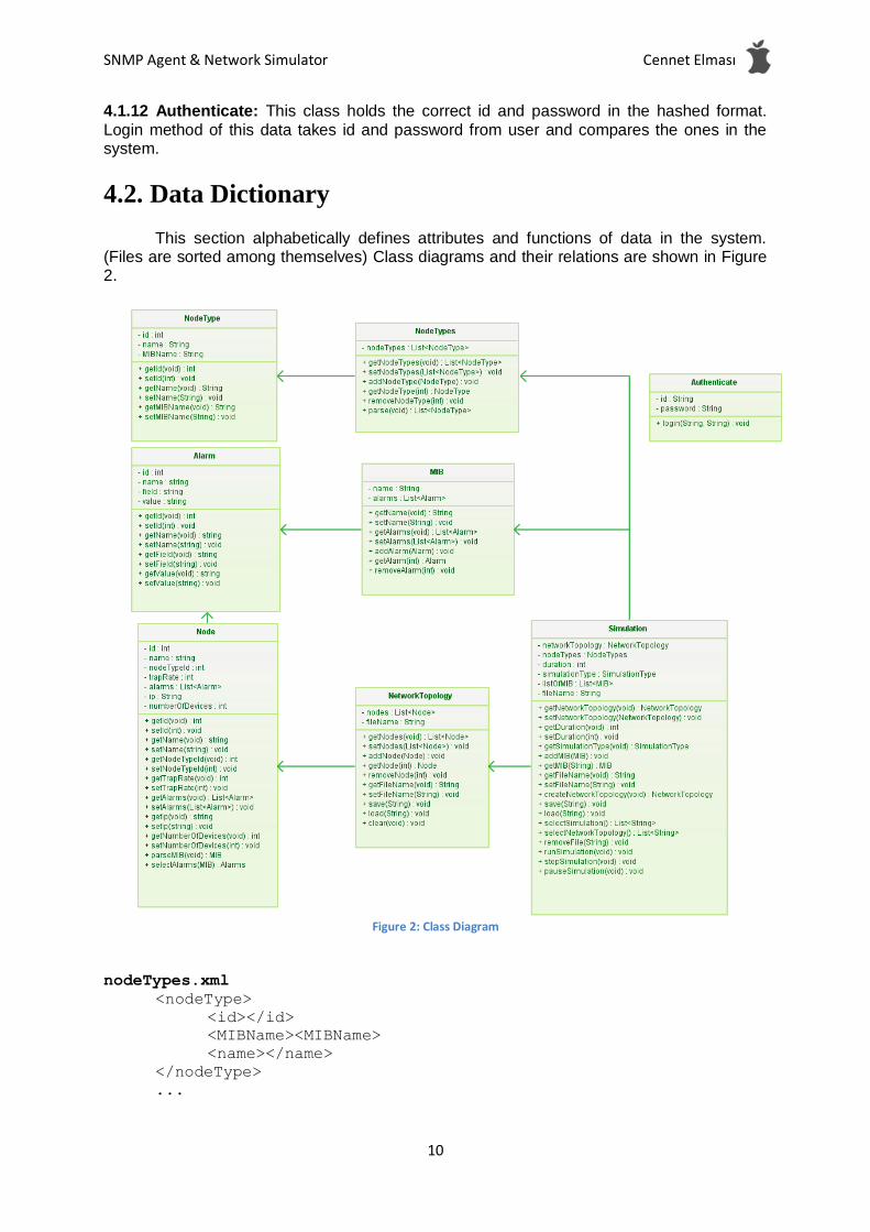
4.1.12 Authenticate: This class holds the correct id and password in the hashed format.
Login method of this data takes id and password from user and compares the ones in the system.
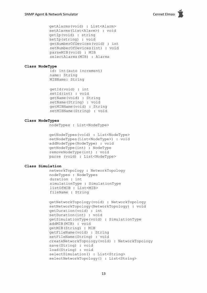
4.2. Data Dictionary
This section alphabetically defines attributes and functions of data in the system. (Files are sorted among themselves) Class diagrams and their relations are shown in Figure 2.
Figure 2: Class Diagram
nodeTypes.xml <nodeType> <id></id> <MIBName><MIBName> <name></name> </nodeType> ...
SNMP Agent & Network Simulator Cennet Elması
11
<userDefinedName-networkTopology>.xml
<node> <id></id>
<name></name> <nodeTypeId></nodeTypeId> <trapRate></trapRate> <alarm>
<id></id> <name></name> <field></field> <value></value>
</alarm> ... <ip></ip> <numberOfDevices></numberOfDevices>
</node> ...
<userDefinedName-simulationConfiguration>.xml
<duration></duration> <simulationType></simulationType> <networkTopology> <node> <id></id>
<name></name> <nodeTypeId></nodeTypeId> <trapRate></trapRate> <alarm>
<id></id> <name></name> <field></field> <value></value>
</alarm> ... <ip></ip> <numberOfDevices></numberOfDevices>
</node> ...
</networkTopology>
Class Alarm id : int
name : string field : string value : string
getId(void) : int setId(int) : void getName(void) : string setName(string) : void getField(void) : string setField(string) : void getValue(void) : string

SNMP Agent & Network Simulator Cennet Elması
12
setValue(string) : void
Class Authenticate id : string password : string
login(string, string) : void
Class MIB name : String alarms : List<Alarm>
getName(void) : String setName(String) : void getAlarms(void) : List<Alarm> setAlarms(List<Alarm>) : void addAlarm(Alarm) : void getAlarm(int) : Alarm removeAlarm(int) : void Class NetworkTopology nodes : List<Node> fileName : String
getNodes(void) : List<Node> setNodes(List<Node>) : void addNode(Node) : void getNode(int) : Node removeNode(int) : void getFileName(void) : String setFileName(String) : void save(String) : void load(String) : void
Class Node id: int
name: string nodeTypeId: int trapRate: int alarms: List<Alarm> ip: String numberOfDevices: int
getId(void): int
setId(int): void getName(void) : string setName(string) : void getNodeTypeId(void) : int setNodeTypeId(int) : void getTrapRate(void) : int setTrapRate(int) : void
SNMP Agent & Network Simulator Cennet Elması
13
getAlarms(void) : List<Alarm> setAlarms(List<Alarm>) : void getIp(void) : string setIp(string) : void
getNumberOfDevices(void) : int setNumberOfDevices(int) : void parseMIB(void) : MIB selectAlarms(MIB) : Alarms
Class NodeType
id: int(auto increment) name: String MIBName: String
getId(void) : int setId(int) : void getName(void) : String setName(String) : void getMIBName(void) : String setMIBName(String) : void
Class NodeTypes
nodeTypes : List<NodeType>
getNodeTypes(void) : List<NodeType> setNodeTypes(List<NodeType>) : void addNodeType(NodeType) : void getNodeType(int) : NodeType removeNodeType(int) : void parse (void) : List<NodeType>
Class Simulation networkTopology : NetworkTopology nodeTypes : NodeTypes
duration : int simulationType : SimulationType listOfMIB : List<MIB> fileName : String
getNetworkTopology(void) : NetworkTopology setNetworkTopology(NetworkTopology) : void getDuration(void) : int setDuration(int) : void getSimulationType(void) : SimulationType addMIB(MIB) : void getMIB(String) : MIB getFileName(void) : String setFileName(String) : void createNetworkTopology(void) : NetworkTopology save(String) : void load(String) : void selectSimulation() : List<String> selectNetworkTopology() : List<String>

SNMP Agent & Network Simulator Cennet Elması
14
removeFile(String) : void runSimulation(void) : void stopSimulation(void) : void pauseSimulation(void) : void
Enum SimulationType realTime, shortenTime
SNMP Agent & Network Simulator Cennet Elması
15
5. System Architecture
5.1. Architectural Design
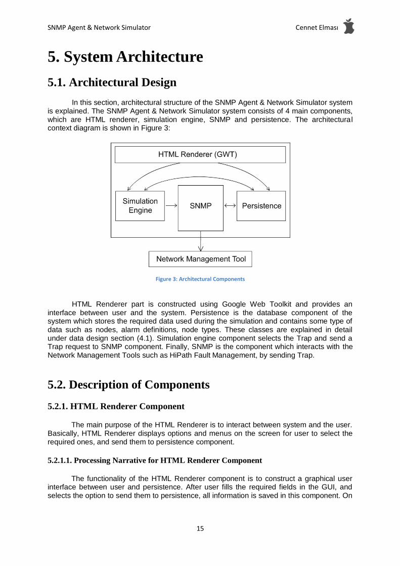
In this section, architectural structure of the SNMP Agent & Network Simulator system is explained. The SNMP Agent & Network Simulator system consists of 4 main components, which are HTML renderer, simulation engine, SNMP and persistence. The architectural context diagram is shown in Figure 3:
Figure 3: Architectural Components
HTML Renderer part is constructed using Google Web Toolkit and provides an
interface between user and the system. Persistence is the database component of the system which stores the required data used during the simulation and contains some type of data such as nodes, alarm definitions, node types. These classes are explained in detail under data design section (4.1). Simulation engine component selects the Trap and send a Trap request to SNMP component. Finally, SNMP is the component which interacts with the Network Management Tools such as HiPath Fault Management, by sending Trap.
5.2. Description of Components
5.2.1. HTML Renderer Component
The main purpose of the HTML Renderer is to interact between system and the user. Basically, HTML Renderer displays options and menus on the screen for user to select the required ones, and send them to persistence component.
5.2.1.1. Processing Narrative for HTML Renderer Component
The functionality of the HTML Renderer component is to construct a graphical user interface between user and persistence. After user fills the required fields in the GUI, and selects the option to send them to persistence, all information is saved in this component. On
SNMP Agent & Network Simulator Cennet Elması
16
the other hand, user can trigger the Simulation Engine component in order to start a simulation.
5.2.1.2. HTML Renderer Component Interface Description
The interface functions of the HTML Renderer component consist of the functions described in section 4.2. These are the functions which are used to manage devices, scenarios, network topologies and start simulation. In conclusion, HTML Renderer constructs a user interface between user and the other components.
5.2.1.3. HTML Renderer Component Processing Detail
Start Display the options and menus on the screen Get input from keyboard or mouse devices Send input to related components Display output if necessary End
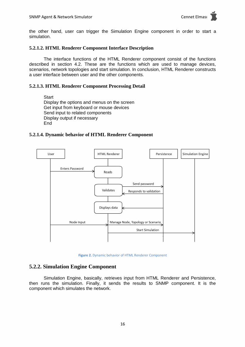
5.2.1.4. Dynamic behavior of HTML Renderer Component
Figure 2. Dynamic behavior of HTML Renderer Component
5.2.2. Simulation Engine Component
Simulation Engine, basically, retrieves input from HTML Renderer and Persistence, then runs the simulation. Finally, it sends the results to SNMP component. It is the component which simulates the network.
SNMP Agent & Network Simulator Cennet Elması
17
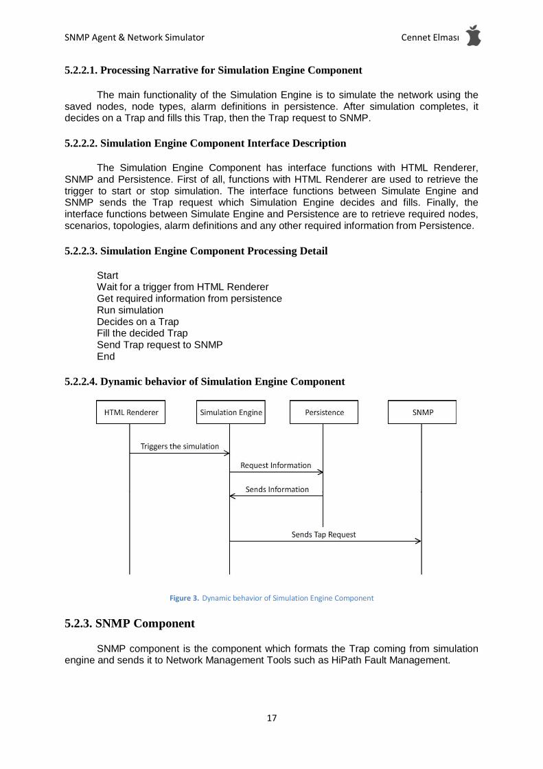
5.2.2.1. Processing Narrative for Simulation Engine Component
The main functionality of the Simulation Engine is to simulate the network using the saved nodes, node types, alarm definitions in persistence. After simulation completes, it decides on a Trap and fills this Trap, then the Trap request to SNMP.
5.2.2.2. Simulation Engine Component Interface Description
The Simulation Engine Component has interface functions with HTML Renderer, SNMP and Persistence. First of all, functions with HTML Renderer are used to retrieve the trigger to start or stop simulation. The interface functions between Simulate Engine and SNMP sends the Trap request which Simulation Engine decides and fills. Finally, the interface functions between Simulate Engine and Persistence are to retrieve required nodes, scenarios, topologies, alarm definitions and any other required information from Persistence.
5.2.2.3. Simulation Engine Component Processing Detail
Start Wait for a trigger from HTML Renderer Get required information from persistence Run simulation Decides on a Trap Fill the decided Trap Send Trap request to SNMP End
5.2.2.4. Dynamic behavior of Simulation Engine Component
Figure 3. Dynamic behavior of Simulation Engine Component
5.2.3. SNMP Component
SNMP component is the component which formats the Trap coming from simulation engine and sends it to Network Management Tools such as HiPath Fault Management.

SNMP Agent & Network Simulator Cennet Elması
18
5.2.3.1. Processing Narrative for SNMP Component
The main functionality of the SNMP component is to construct output and send it to Network Management Tools.
5.2.3.2. SNMP Component Interface Description
The interface functions of SNMP component are those are with persistence and simulation engine. The interface functions which are between SNMP and simulation engine are to send Trap request from simulation engine to SNMP to construct output. On the other hand, the functions between SNMP and persistence are the ones which send reports between SNMP and persistence to compare or save reports.
5.2.3.3. SNMP Component Processing Detail
Start Wait for a Trap request Send them to Network Management Tool as output Wait for save report request Save reports to persistence Wait for compare request Get reports from persistence Compare reports End
5.2.3.4. Dynamic behavior of SNMP Component
Figure 4. Dynamic behavior of SNMP Component
5.2.4. Persistence Component
Persistence component is the database part which keeps the information about saved data such as nodes, node types, scenarios and so on.
SNMP Agent & Network Simulator Cennet Elması
19
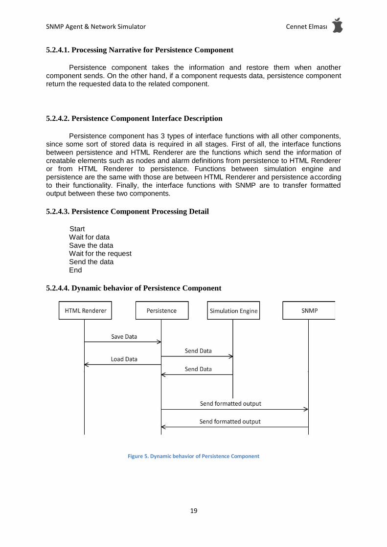
5.2.4.1. Processing Narrative for Persistence Component
Persistence component takes the information and restore them when another component sends. On the other hand, if a component requests data, persistence component return the requested data to the related component.
5.2.4.2. Persistence Component Interface Description
Persistence component has 3 types of interface functions with all other components, since some sort of stored data is required in all stages. First of all, the interface functions between persistence and HTML Renderer are the functions which send the information of creatable elements such as nodes and alarm definitions from persistence to HTML Renderer or from HTML Renderer to persistence. Functions between simulation engine and persistence are the same with those are between HTML Renderer and persistence according to their functionality. Finally, the interface functions with SNMP are to transfer formatted output between these two components.
5.2.4.3. Persistence Component Processing Detail
Start Wait for data Save the data Wait for the request Send the data End
5.2.4.4. Dynamic behavior of Persistence Component
Figure 5. Dynamic behavior of Persistence Component

SNMP Agent & Network Simulator Cennet Elması
20
5.3. Design Rationale
In order to achieve the goal of the simulation, system needs basic components. These components are HTML Renderer, simulation engine, SNMP and persistence. All these components have basic functionalities so that, in case of lack of any of these components, system may have troubles. On the other hand, there is no need for a fifth component since these four components handle all the work in the simulation. Moreover, an unnecessary fifth component may cause slow reaction and extra effort in the system. Therefore, this design best fits the situation to solve the problem.
SNMP Agent & Network Simulator Cennet Elması
21
6. User Interface Design
6.1. Overview of User Interface
In SNMP Agent Simulator user can access the system from web-browser and below there are functionalities that user can reach.
1. Login/Logout (Figure 8) 2. Create, Load and Save Simulation (Figure 9) 3. Add, Edit and Remove NodeType 4. Create, Load and Save NetworkTopology (Figure 10) 5. Select, Drag and Drop NodeType 6. Add, Edit and Remove Node, Select Alarm for Node (Figure 11, Figure 12) 7. Start, Pause and Stop simulation (Figure 13) 8. Remove saved files before
For functions that mentioned above have feedback mechanism and messages and
they are listed below
- For 1st, 2nd, 3rd, 5th and 7th functionalities system should give feedback about operation is completed successfully or not.
- For 7th functionality system ask for confirmation to do remove operation.
- For 4th functionality system should show selected NodeType in a different style and
when a NodeType is dragged there should be a box which corresponds to selected NodeType, follows user controlled pointer.
- For 6th functionalities when simulation is started left bar is disabled and console is
opened at the left. The caught alarms and errors logged in the console. If simulation paused this information is showed on the console and until simulations are started again there should be no log on the console.
- When simulation is started state of nodes will be shown different color.
- If user logged in the system and a simulation is running at this moment there should
be a message that inform the user about this situation.
- If user in the configuration window and decides to work on a new simulation, system
should ask to user to save the current simulation.

SNMP Agent & Network Simulator Cennet Elması
22
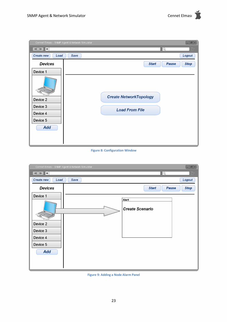
6.2. Screen Images
Figure 6: Login Screen
Figure 7: Start Window
SNMP Agent & Network Simulator Cennet Elması
23
Figure 8: Configuration Window
Figure 9: Adding a Node Alarm Panel

SNMP Agent & Network Simulator Cennet Elması
24
Figure 10: Nodes in the System
Figure 11: Simulation Window

SNMP Agent & Network Simulator Cennet Elması
25
6.3. Screen Objects and Actions
This section describes the actions of the objects that parts of the user interface. Below objects are listed at each window.
Login Window - Id and Password Fields: They are text field and filled by the user. - Login: It is a button that sends filled form to server and if given id and passwords are
correct, redirects users to Start Window. It calls the login method of Authenticate class.
Start Window - Create: It is a button that creates new simulation and redirects user to configuration
window. It creates a new simulation object in the system. - Load: It is a button that loads saved a simulation and redirects to configuration
window. It creates a new simulation object and fills the attributes read values from file. - Analyze the previous results: It shows the results of the previous simulations.
Configuration Window - Select NodeType: When user clicks NodeType, it is selected. - Drag and Drop NodeType: When user drags the selected NodeType, a box which
represents NodeType follows pointer, when it released, it creates a Node on the NetworkTopology
- Edit NodeType: It is a button and opens a panel consist of text fields. In the text field NodeType’s attributes are shown.
- Remove NodeType: It is a button removes the selected NodeType - Add NodeType: It is a button and opens a panel consist of text fields. User enters
needed information to the text fields. - Create new NetworkTopology: It is a button and creates a NetworkTopology object - Load NetworkTopology: It is a button and creates a NetworkTopology object and
sets attributes according to selected file’s values. It opens a panel to show recorded files previously and user selects a file name from there.
- Save NetworkTopology: It is a button and saves the current NetworkTopology to a file. It opens a panel to request a file name from user.
- Remove NetworkTopology: It is a button and removes the selected NetworkTopology file.
- Save Simulation: It is a button and saves the current Simulation Configuration to a file. It opens a panel to request a file name from user.
- Load Simulation: It is a button and sets attributes of simulation according to selected file’s values.
- Remove Simulation: It is a button and removes the selected Simulation file. - Run Simulation: It is a button that starts the simulation left bar is disabled and
console is opened. - SimulationType: It is drop-drown selection, user selects the SimulationTypes - Name: It is a text box for name of simulation. - Duration: It is a text field, user enters the time that simulation should how much time
runs.
NodeType Panel - Name: It is a text field for name of NodeType - MIB file name: It is a text field for name of MIB.

SNMP Agent & Network Simulator Cennet Elması
26
Alarm Panel - Alarms: alarms are listed and next of each there are check boxes to select them.
Simulation Window - Pause Simulation: It is a button pauses the simulation. - Run Simulation: It is a button - Stop Simulation: - Time: it shows elapsed time and remaining time. - Console: It shows the caught alarms and messages.
SNMP Agent & Network Simulator Cennet Elması
27
7. Detailed Design
7.1 HTML Renderer Component
Classification: HTML Renderer is one of the major components under system architecture. Definition: In order to interact with user and system, an interface component is needed. For this purpose, HTML Renderer component is required. HTML Renderer component constructs a graphical user interface between user and other components. Responsibilities: Since HTML Renderer component acts as a user interface, it provides some input fields and buttons for specific purposes to the user. These purposes are listed as creating a new simulation, loading a simulation, saving a simulation, creating, updating and deleting devices, running and stopping simulations, creating, updating and deleting network topologies and scenarios. This component provides services related to simulation which will be run and nodes which is kept in the database. Constraints: There is no constraint related to this component. Composition: There is no subcomponent of this component. Uses/Interactions: HTML Renderer component has interactions with persistence component and simulation engine component. First of all, user fill the required areas to create node in the system and after system gets trigger, such as “create node” button is pressed, the information which user enters to the input fields on the screen is sent to the persistence part and saved to database in .xml structure.
Finally, when user presses on “run simulation” button, it triggers simulation engine and simulation begins. Similarly, when a simulation is running, if “pause simulation” or “stop simulation” buttons are pressed, it stops or pauses the running simulation. In these interactions, interface methods are the methods under simulation engine component which is used to start, pause and stop the simulation. Resources:
HTML Renderer has a direct effect on saved data in persistence component as .xml documents for its create, update and delete node functionalities. When user creates a node, scenario and network topology, it is saved into persistence in .xml structure. When the user selects one of the saved items in persistence, all the required fields are retrieved from related xml document and displayed on the screen. If user wants to update a field of an item, it updates the xml file of the selected item. Similarly, if a user wants to delete an item, xml document in persistence is deleted, too.
Since we have only one user, there is no race condition in this source usage. Processing:
It was created on the server side and rendered files showed to user. Interface/Exports: This component is a graphical user interface between components of the system and the user.
SNMP Agent & Network Simulator Cennet Elması
28
7.2 Persistence Component
Classification: Persistence component is the one of the major components under system architecture. Definition: In order to use data for several times, we need to save this data somewhere in the system. In order to achieve this, we need a database component which will keep all nodes and items that will be used in the system for future requirements. Persistence component, as easily can be recognized from its name, is the database component in the system. Responsibilities: Persistence component basically keeps data in xml structure whenever other components triggers storing functionality and returns saved data from xml structure whenever another component requests data. Composition: nodeTypes.xml,
<userDefinedName-networkTopology>.xml, <userDefinedName-simulationConfiguration>.xml
Uses/Interactions: HTML Rendered uses the files under this component. Resources: The resources of this component are entered by the user and initial device and MIB files provided by Siemens. Processing: This component processed on the server side according to request from the other components. Stored files under this component are read by using SAX parser and data structures are created. Interface/Exports:
7.3 Simulation Engine Component
Classification: Simulation engine component is the one of the major components under system
architecture. Definition: Simulation engine component is basically the part that simulation runs in the system. Responsibilities: After triggered by related button in HTML Renderer, simulation engine runs the simulation using data stored in persistence component. Simulation engine decides on a Trap and sends a request for this Trap to SNMP component. Constraints: Simulation Engine can simulate up to 20.000 devices at the same time. Composition: There is no subcomponent of simulation engine component. Uses/Interactions: Simulation engine component has interactions with all other major components. First of all, simulation engine component starts running or stops with the trigger come from HTML Renderer. Interface methods are simply those which defined to create a simulation or give a break to running simulation.
SNMP Agent & Network Simulator Cennet Elması
29
Secondly, in order to use predefined data in a simulation, simulation engine interacts with persistence component. These interaction is retrieving required data from xml structure. Interface methods are those which defined to read a specified field from xml structure. Finally, the interaction between simulation engine component and SNMP component is constructed to send Trap requests from simulation engine to SNMP component. Resources: During the simulation, simulation engine component uses the data which is stored in xml structure in persistence component. Processing:
This component processed on the server side and result sent to the client side for analyzing. Interface/Exports:
7.4 SNMP Component
Classification: SNMP component is the one of the major components under system architecture.
Definition: SNMP component is the component which formats the Trap coming from simulation engine and sends it to Network Management Tools such as HiPath Fault Management. Responsibilities:
SNMP component exposes management data in the form of variables on the managed systems, which describe the system configuration. Constraints: Composition: An SNMP-managed network consists of three key components, which are managed device, agent and network management system (NMS).
A managed device is a network node that implements an SNMP interface that allows unidirectional (read-only) or bidirectional access to node-specific information. Managed devices exchange node-specific information with the NMSs. Sometimes called network elements, the managed devices can be any type of device, including, but not limited to, routers, access servers, switches, bridges, hubs,IP telephones, IP video cameras, computer hosts, and printers.
An agent is a network-management software module that resides on a managed device. An agent has local knowledge of management information and translates that information to or from an SNMP specific form.
A network management system (NMS) executes applications that monitor and control managed devices. NMS's provide the bulk of the processing and memory resources required for network management. One or more NMSs may exist on any managed network. Uses/Interactions:
SNMP has interactions with simulation engine component, persistence component and network management tools which are external software.
First of all, the interaction between simulation engine component and SNMP component is required to send Trap request from simulation engine to SNMP. In order to achieve this interaction, some specific functions are defined under SNMP class. These functions are as follows: 1. GetRequest: A manager-to-agent request to retrieve the value of a variable or list of
variables. Desired variables are specified in variable bindings (values are not used).
Retrieval of the specified variable values is to be done as an atomic operation by the agent.
A Response with current values is returned.
SNMP Agent & Network Simulator Cennet Elması
30
2. SetRequest: A manager-to-agent request to change the value of a variable or list of
variables. Variable bindings are specified in the body of the request. Changes to all specified
variables are to be made as an atomic operation by the agent. A Response with (current)
new values for the variables is returned.
3. GetNextRequest: A manager-to-agent request to discover available variables and their
values. Returns a Response with variable binding for the lexicographically next variable in
the MIB. The entire MIB of an agent can be walked by iterative application of
GetNextRequest starting at OID 0. Rows of a table can be read by specifying column OIDs in
the variable bindings of the request.
4. GetBulkRequest: Optimized version of GetNextRequest. A manager-to-agent request for
multiple iterations of GetNextRequest. Returns a Response with multiple variable bindings
walked from the variable binding or bindings in the request. PDU specific non-repeaters and
max-repetitions fields are used to control response behavior. GetBulkRequest was
introduced in SNMPv2.
Response: Returns variable bindings and acknowledgement from agent to manager for
GetRequest, SetRequest, GetNextRequest, GetBulkRequest and InformRequest. Error
reporting is provided by error-statusand error-index fields. Although it was used as a
response to both gets and sets, this PDU was called GetResponse in SNMPv1. Trap: Asynchronous notification from agent to manager. Includes current sysUpTime value,
an OID identifying the type of trap and optional variable bindings. Destination addressing for
traps is determined in an application specific manner typically through trap configuration
variables in the MIB. The format of the trap message was changed in SNMPv2 and the PDU
was renamed SNMPv2-Trap.
InformRequest: Acknowledged asynchronous notification from manager to manager. This
PDU uses the same format as the SNMPv2 version of Trap. Manager-to-manager
notifications were already possible in SNMPv1 (using a Trap), but as SNMP commonly runs
over UDP where delivery is not assured and dropped packets are not reported, delivery of a
Trap was not guaranteed. InformRequest fixes this by sending back an acknowledgement on
receipt. Receiver replies with Response parroting all information in the InformRequest. This
PDU was introduced in SNMPv2.
Resources: Instead of defining which information a managed system should offer, SNMP uses an
extensible design, where the available information is defined by MIBs. MIBs describe the structure of the management data of a device subsystem; they use a hierarchical namespace containing object identifiers (OID). Each OID identifies a variable that can be read or set via SNMP. These MIBs are stored in persistence component under a special structure, which is specific for MIB files.
Moreover, SNMP uses the other items stored in persistence such as nodes, nodetypes. However, this usage is read-only; therefore, SNMP component doesn’t have an effect on this data. Processing: All the devices will have SNMP in their default configuration. SNMP will run SNMP-agent on the devices. SNMP-agent will send periodic traps to the Simulation Engine(?). Interface/Exports: This component produce outputs for Network Management Tool that supports SNMP.

SNMP Agent & Network Simulator Cennet Elması
31
8. Libraries and Tools
8.1 Google Web Toolkit (GWT)
SNMP Agent Simulator is a web-based application and user interfaces are web-pages, so that windows should be rendered to HTML pages. GWT is a development kit for developing web-based applications. It is open source and it simplifies to create HTML pages. It converts Java codes to JavaScript code and enables writing CSS code for style of objects. At the server side it allows any language but Java will be good choice for this project.
8.2 jSNMP
jSNMP provides complete SNMP v1/v2c/v3 support including trap/inform handling. A traditional Java SNMP SDK, Java SNMP API, or SNMP Java library requires the user to manually construct SNMP request packets. The jSNMP interface, however, allows the user to communicate with network devices by specifying the Object Identifier (OID) of interest rather than worrying about the confusions of SNMP.
jSNMP has been optimized for minimizing network traffic and maximizing efficiency,
allowing for a high degree of scalability. In addition, the package has been optimized for use with multiple simultaneous connections.
8.3 Google App Engine
SNMP Agent Simulator runs on Google App Engine. Google App Engine enables to build and host web apps on the same systems that power Google applications. App Engine offers fast development and deployment; simple administration, with no need to worry about hardware, patches or backups; and effortless scalability.
8.4 Google Code
For subversion project hosting service Google Code provides free space for development. During the development it is used for synchronization of the current version of project.
8.5 Eclipse Plug-in
The plug-in for Eclipse provides IDE support for Google Web Toolkit and App Engine web projects.
8.6 SAX XML Parser
Sax XML Parser is used for parse the xml files stored in the system.

SNMP Agent & Network Simulator Cennet Elması
32
8.7 Mibble MIB Parser
Mibble is an open-source SNMP MIB parser written in Java. It can be used to read SNMP MIB files as well as simple. Mibble is distributed as a Java library to make it possible to include it in your applications.

SNMP Agent & Network Simulator Cennet Elması
33
9. Time Planning
9.1 Term 1 Gannt Chart
1. User Interface Design
2. Design of Devices
3. Design of Network Topology
4. Design of Scenario
5. Installing Software and Libraries
6. Implenting User Interface
7. Preparing Demo

SNMP Agent & Network Simulator Cennet Elması
34

SNMP Agent & Network Simulator Cennet Elması
35
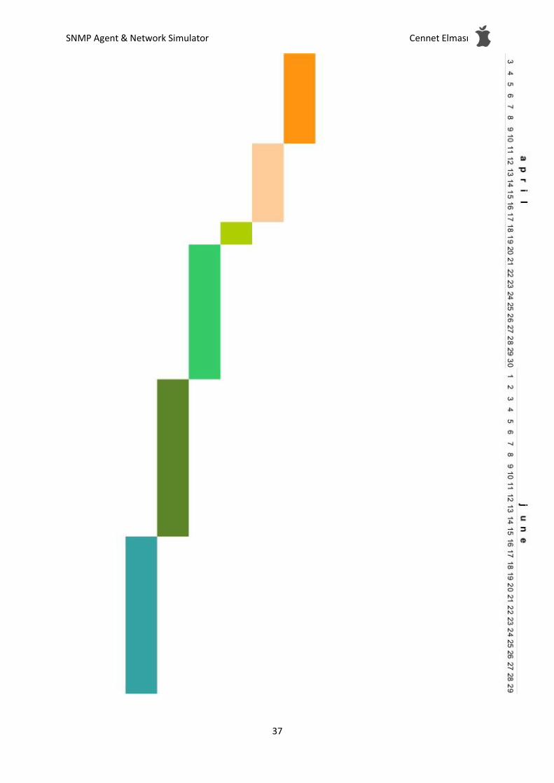
9.2 Term 2 Gannt Chart
1. Small Applications for Server Client Architecture
2. Parsing Files (XML and MIB)
3. Adding, Editing, Removing Devices
4. Creating Network
5. Adding, Editing, Removing Devices To Network
6. Implementing Persistence Component
7. Implementing Simulation Engine Component
8. Implenting SNMP Component
9. Implementing Interface For Analyzing
10. Running Simulation For One Device
11. Running simulation For a subnet
12. Running simulation For Multiple Subnets

SNMP Agent & Network Simulator Cennet Elması
36
SNMP Agent & Network Simulator Cennet Elması
37

SNMP Agent & Network Simulator Cennet Elması
38
10. Conclusion
This Detailed Design Report is written to give detailed information about the design patterns of SNMP Agent & Network Simulator project. In this document, first of all, the system overview is represented and constraints, assumptions and dependencies are stated. Then, data structures and architectural components are defined and explained briefly. User interface is represented and information is given about libraries which will be used in developing the product. The algorithms and relations between components determined in detail. Finally, the process schedule is given in gannt chart notation at the end of the document.
This document finalizes all design issues of SNMP Agent & Network Simulataor Project and gives the required information to implement this project.