Embed Size (px)
Citation preview
Purdue UniversityPurdue e-Pubs
International Compressor Engineering Conference School of Mechanical Engineering
2018
Detailed Thermal Model of an Open-Drive Single-Screw Expander for ORC ApplicationsDavide ZivianiSchool of Mechanical Engineering, Ray W. Herrick Laboratories, Purdue University, [email protected]
Michel De [email protected]
James E. BraunPurdue University - Main Campus, [email protected]
Eckhard A. GrollPurdue University - Main Campus, [email protected]
Follow this and additional works at: https://docs.lib.purdue.edu/icec
This document has been made available through Purdue e-Pubs, a service of the Purdue University Libraries. Please contact [email protected] foradditional information.Complete proceedings may be acquired in print and on CD-ROM directly from the Ray W. Herrick Laboratories at https://engineering.purdue.edu/Herrick/Events/orderlit.html
Ziviani, Davide; De Paepe, Michel; Braun, James E.; and Groll, Eckhard A., "Detailed Thermal Model of an Open-Drive Single-ScrewExpander for ORC Applications" (2018). International Compressor Engineering Conference. Paper 2617.https://docs.lib.purdue.edu/icec/2617
1495, Page 1
Detailed Thermal Model of Open-Drive Single-Screw Expanders for ORCApplications
Davide ZIVIANI1*, Michel DE PAEPE2, James E. BRAUN1, Eckhard A. GROLL1
1 Ray W. Herrick Laboratories, School of Mechanical Engineering, Purdue UniversityWest Lafayette, 47907-2099, USA
2 Ghent University, Department of Flow, Heat and Combustion Mechanics,Ghent, 9000, Belgium
[email protected], [email protected], [email protected], [email protected]
* Corresponding Author
ABSTRACT
A comprehensive mechanistic model of an open-drive single-screw expander for waste heat recovery applications bymeans of an Organic Rankine Cycle (ORC) has been previously developed and validated by the authors. The modelincluded sub-models of geometry, leakage flows, in-chamber heat transfer, simplified friction losses and a single-lumped temperature overall energy balance. Furthermore, a non-symmetric approachwas also implemented to simulatethe simultaneous expansion process occurring on both side of the central rotor. In this work, the mechanistic model hasbeen extended to compute the loads on the starwheels bearings as well as the main rotor. Forces and moments analysesallowed integration of a more detailed friction loss analysis and identification of a thermal resistance network of thehousing with multiple lumped temperatures. To the best of the author’s knowledge such a detailed integrated thermalmodel of a single-screwmachine has not been reported in the available literature. Themulti-lumped temperature overallenergy balance (OEB) is validated with experimental data obtained from a dedicated ORC test stand. A comparisonbetween single-lumped and multi-lumped temperature approaches on the performance predictions is provided alongwith a discussion about the losses distribution inside the machine.
1. INTRODUCTION
Deterministic models of single-screw compressors (SSC) and expanders (SSE) have been published in literature. Oneof the first computer models reported in the literature was proposed by Bein and Hamilton (1982) for a low pressure oil-flooded single-screw air compressor. An iterative approach based on a polytropic transformation was used to correlateinternal predictions with empirical values. Leakage paths were also considered, neglecting the two-phase flow throughthe gaps. The heat transfer between the air in the compression chamber and oil was neglected. Successively, Boblittand Moore (1984) presented a FORTRAN-based computer model of an oil-flooded SSC operating at 100% capacity atmatched discharge pressures, meaning the pressure at the end of the compression process corresponded exactly withthe discharge pressure. The model is based on two empirical parameters, i.e. polytropic compression efficiency and thedischarge flow coefficient. The included leakage model is based on the model proposed by Bein and Hamilton (1982),with the addition of the effect of the oil on the volumetric and isentropic efficiency. However, it was assumed thatonly oil was leaking from the groove tip sealing lines and the refrigerant leakages were restricted to the the dischargeport. The heat transfer between the refrigerant and oil in the closed compression process was neglected. The oilinjection process was also included in the model. A total of six control volumes were introduced to analyze the overallcompression process. Thermal interactions between each control volumes were modeled by means of a steady-statesteady-flow First Law analysis. The closed compression process was divided into a number of steps corresponding toa pressure increment, since the discharge state of a groove had to match the discharge pressure. The main rotor rotationstep was a result of the model. Wu and Jin (1988) and Hirai et al. (1986) included additional gas-oil mixture effectsinto their compressor models as well as the analysis of a slide valve mechanism.
More recently, Wang et al. (2016) presented a detailed thermodynamic model of a SSC with multi-column meshingprofile in which continuity and energy conservation equations were applied to the refrigerant gas and lubricant oil.The control volume analysis was applied to a single working chamber by assuming that all the others behaved in a
24th International Compressor Engineering Conference at Purdue, July 9-12, 2018
1495, Page 2
similar manner. Suction gas heating due to the presence of the motor was also included. A two-phase flow modelwas employed to calculate the flow rate through the discharge port. A correction coefficient was introduced basedupon experimental data. The heat transfer within the working chamber was modeled by including a correction factorto account for the helical shape of the groove. Cooling capacity and shaft power were validated with experimentaldata. The same authors extended the chamber model to investigate the effect of liquid refrigerant injection to reducethe discharge temperature and to improve the compressor performance (Wang et al. (2018)).
With respect to expanders, Ziviani et al. (2014) and Shen et al. (2018) developed comprehensive models of single-screw expanders for organic Rankine cycle applications by accounting for both leakage and frictional losses. Themodels have been used to predict the performance of the machines and to determine the effect of leakage gaps andoperating conditions on the overall performance.
By analyzing all the models proposed in literature, the overall energy balance of the single-screw machine is not welladdressed especially in the case of hermetic or semi-hermetic designs. Ziviani et al. (2014) enforced a single-lumpedtemperature energy balance to estimate the heat losses through the shell. However, such approach, although effective,is not sufficient to have better understanding of the thermal interactions inside the machine as well as identifying thethermal losses.
In this paper, a detailed overall housing energy balance with a multi-lumped temperature thermal network is proposedand integrated into the detailed expander model. An 11 kWe single-screw expander working with R245fa has beenselected as test case to validate the model and perform analyses. The experimental data points of the expander areavailable from a previous study (Ziviani et al. (2016)).
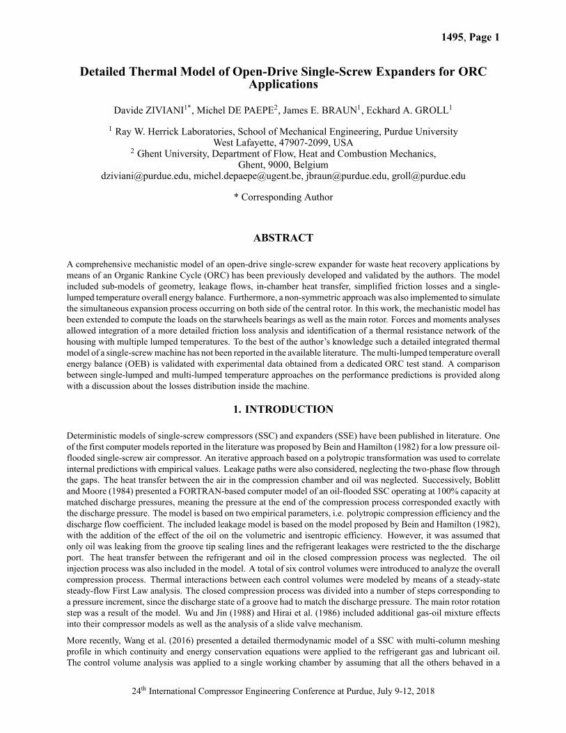
Figure 1: Views of the single-screw expander assembly with the direction of rotation of meshing pair (left) and thecontrol volumes (right).
2. NON-SYMMETRIC MODELING APPROACH
The operating principle of a single-screw expander is based on the simultaneous filling of the grooves on both sides ofthe main rotor through ports located on the internal cylindrical surface of the housing which hosts the main rotor. Asa groove rotates, it is exposed to the suction port until the trailing edge passes over the port. Once the portion of thegroove limited by the engaging tooth, by the three sides of the groove and the housing wall is filled with working fluid,the closed expansion occurs until the tooth starts disengaging the groove, when the discharge process begins. Suchprocess occurs on both sides of the main rotor and therefore, when a groove is discharging on one side, it is filling onthe other side at the same time. Each groove is employed twice per revolution. By looking at Figure 1, the main rotor
24th International Compressor Engineering Conference at Purdue, July 9-12, 2018
1495, Page 3
has six grooves, but due to the fact that two starwheels are engaged at the same time, there are six working chamberson each side of the rotor, as mentioned by Wang et al. (Wang et al., 2016). To reduce the complexity of the model, it iscommon practice to consider only one side of the rotor due to symmetry. A more general approach is adopted in thiswork. In particular, a non-symmetric description of the machine is considered by computing the expansion process inboth sides of the rotor. By referring to Figure 1, the housing has been divided into four static control volumes (CV)which are associated with the common inlet volume, the two internal ducts that connects the inlet to the suction pocketsand shell volume connected to the outlet of the expander. On each side of the rotor, six dynamic control volumes whichare changing according to the rotation angle are representative of the six working chambers. The rotation of the mainrotor is taken as reference. To relax the notation, the rotation angle of the main rotor, θsr, will be referred to as θ, unlessspecified. A summary of the control volume definitions is available in Table 1
Table 1: Definition of the different control volumes in the single-screw expander.
Type Description Geometry
Static
inletshellinletshell.1inletshell.2outletshell
V = 69 cm3, dV = 0 cm3
V = 70 cm3, dV = 0 cm3
V = 120 cm3, dV = 0 cm3
V = 569 cm3, dV = 0 cm3
Dynamic G1,...,G6 V=V(θ), dV=dV(θ) (Ziviani et al. (2018))
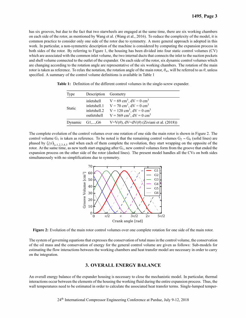
The complete evolution of the control volumes over one rotation of one side the main rotor is shown in Figure 2. Thecontrol volume G1 is taken as reference. To be noted is that the remaining control volumes G2 � G6 (solid lines) arephased by �jγi�j�1,2,3,4,5 and when each of them complete the revolution, they start wrapping on the opposite of therotor. At the same time, as new teeth start engaging after G1, new control volumes form from the groove that ended theexpansion process on the other side of the rotor (dashed lines). The present model handles all the CVs on both sidessimultaneously with no simplifications due to symmetry.
0 π/2 π 3π/2 2π 5π/2
Crank angle [rad]
0
10
20
30
40
50
60
70
Gro
ove
Volu
me [
cm3] G1
G2
G3
G4
G5
G6
Figure 2: Evolution of the main rotor control volumes over one complete rotation for one side of the main rotor.
The system of governing equations that expresses the conservation of total mass in the control volume, the conservationof the oil mass and the conservation of energy for the general control volume are given as follows: Sub-models forestimating the flow interactions between the working chambers and heat transfer model are necessary in order to carryon the integration.
3. OVERALL ENERGY BALANCE
An overall energy balance of the expander housing is necessary to close the mechanistic model. In particular, thermalinteractions occur between the elements of the housing the working fluid during the entire expansion process. Thus, thewall temperatures need to be estimated in order to calculate the associated heat transfer terms. Single-lumped temper-
24th International Compressor Engineering Conference at Purdue, July 9-12, 2018
1495, Page 4
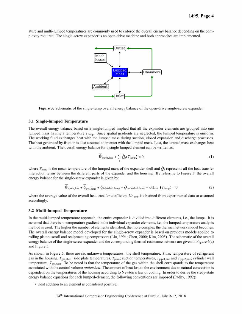
ature and multi-lumped temperatures are commonly used to enforce the overall energy balance depending on the com-plexity required. The single-screw expander is an open-drive machine and both approaches are implemented.
LumpedMass Chambers
Inlet
Outlet
Mech.losses
Ambient
Figure 3: Schematic of the single-lump overall energy balance of the open-drive single-screw expander.
3.1 Single-lumped TemperatureThe overall energy balance based on a single-lumped implied that all the expander elements are grouped into onelumped mass having a temperature Tlump. Since spatial gradients are neglected, the lumped temperature is uniform.The working fluid exchanges heat with the lumped mass during suction, closed expansion and discharge processes.The heat generated by friction is also assumed to interact with the lumped mass. Last, the lumped mass exchanges heatwith the ambient. The overall energy balance for a single lumped element can be written as,
Wmech,loss �QiQi�Tlump� � 0 (1)
where Tlump is the mean temperature of the lumped mass of the expander shell and Qi represents all the heat transferinteraction terms between the different parts of the expander and the housing. By referring to Figure 3, the overallenergy balance for the single-screw expander is given by:
Wmech,loss � Qcyl,lump � Qinletshell,lump � Qoutletshell,lump �UAamb �Tlump� � 0 (2)
where the average value of the overall heat transfer coefficient UAamb is obtained from experimental data or assumedaccordingly.
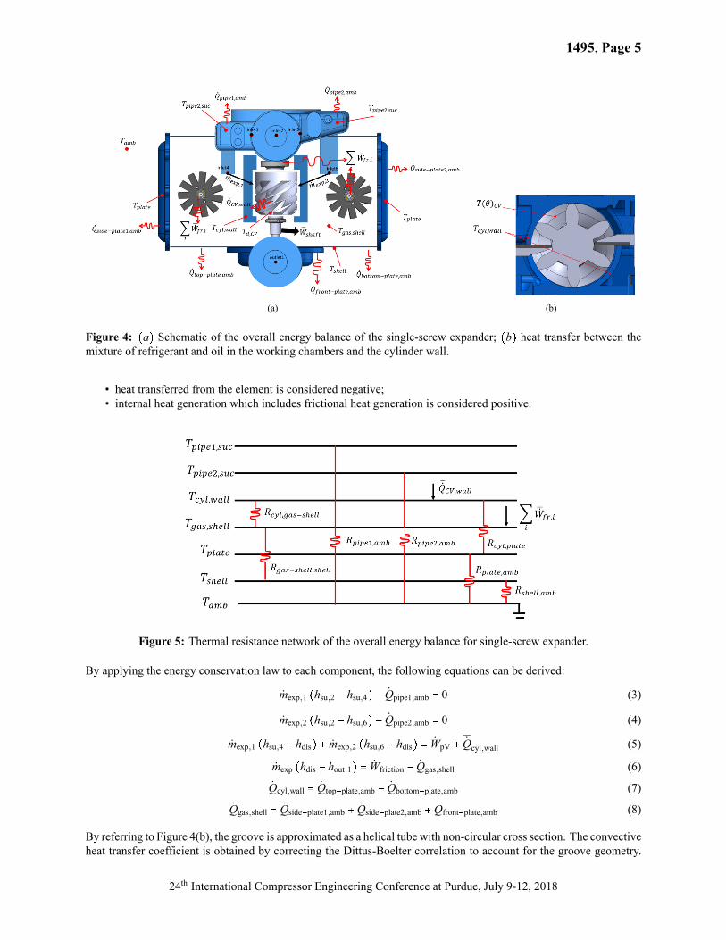
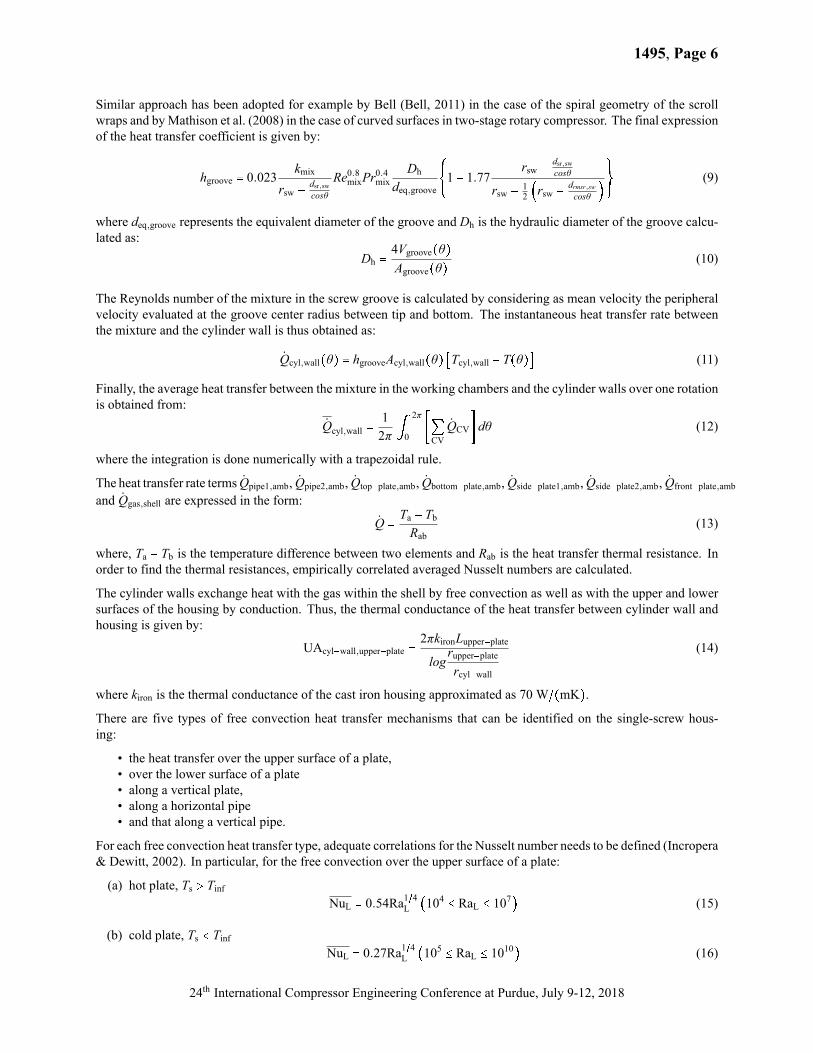
3.2 Multi-lumped TemperatureIn the multi-lumped temperature approach, the entire expander is divided into different elements, i.e., the lumps. It isassumed that there is no temperature gradient in the individual expander elements, i.e., the lumped temperature analysismethod is used. The higher the number of elements identified, the more complex the thermal network model becomes.The overall energy balance model developed for the single-screw expander is based on previous models applied torolling piston, scroll and reciprocating compressors (Liu, 1994; Chen, 2000; Kim, 2005). The schematic of the overallenergy balance of the single-screw expander and the corresponding thermal resistance network are given in Figure 4(a)and Figure 5.
As shown in Figure 5, there are six unknown temperatures: the shell temperature, Tshell; temperature of refrigerantgas in the housing, Tgas,shell; side plate temperatures, Tplate; suction temperatures, Tpipe1,suc and Tpipe2,suc; cylinder walltemperature, Tcyl,wall. To be noted is that the temperature of the gas within the shell corresponds to the temperatureassociated with the control volume outletshell. The amount of heat lost to the environment due to natural convection isdependent on the temperatures of the housing according to Newton’s law of cooling. In order to derive the stedy-stateenergy balance equations for each lumped-element, the following conventions are imposed (Padhy, 1992):
• heat addition to an element is considered positive;
24th International Compressor Engineering Conference at Purdue, July 9-12, 2018
1495, Page 5
(a) (b)
Figure 4: �a� Schematic of the overall energy balance of the single-screw expander; �b� heat transfer between themixture of refrigerant and oil in the working chambers and the cylinder wall.
• heat transferred from the element is considered negative;• internal heat generation which includes frictional heat generation is considered positive.
Figure 5: Thermal resistance network of the overall energy balance for single-screw expander.
By applying the energy conservation law to each component, the following equations can be derived:
mexp,1 �hsu,2 � hsu,4� � Qpipe1,amb � 0 (3)
mexp,2 �hsu,2 � hsu,6� � Qpipe2,amb � 0 (4)
mexp,1 �hsu,4 � hdis� � mexp,2 �hsu,6 � hdis� � WpV � Qcyl,wall (5)
mexp �hdis � hout,1� � Wfriction � Qgas,shell (6)
Qcyl,wall � Qtop�plate,amb � Qbottom�plate,amb (7)
Qgas,shell � Qside�plate1,amb � Qside�plate2,amb � Qfront�plate,amb (8)
By referring to Figure 4(b), the groove is approximated as a helical tube with non-circular cross section. The convectiveheat transfer coefficient is obtained by correcting the Dittus-Boelter correlation to account for the groove geometry.
24th International Compressor Engineering Conference at Purdue, July 9-12, 2018
1495, Page 6
Similar approach has been adopted for example by Bell (Bell, 2011) in the case of the spiral geometry of the scrollwraps and byMathison et al. (2008) in the case of curved surfaces in two-stage rotary compressor. The final expressionof the heat transfer coefficient is given by:
hgroove � 0.023kmix
rsw �dsr,swcosθ
Re0.8mixPr0.4mix
Dh
deq,groove
¢¦¤1 � 1.77rsw �
dsr,swcosθ
rsw � 12 �rsw � drmsr,sw
cosθ �£§¥ (9)
where deq,groove represents the equivalent diameter of the groove and Dh is the hydraulic diameter of the groove calcu-lated as:
Dh �4Vgroove�θ�Agroove�θ� (10)
The Reynolds number of the mixture in the screw groove is calculated by considering as mean velocity the peripheralvelocity evaluated at the groove center radius between tip and bottom. The instantaneous heat transfer rate betweenthe mixture and the cylinder wall is thus obtained as:
Qcyl,wall�θ� � hgrooveAcyl,wall�θ� �Tcyl,wall � T�θ�� (11)
Finally, the average heat transfer between the mixture in the working chambers and the cylinder walls over one rotationis obtained from:
Qcyl,wall �12π S
2π
0�QCV
QCVdθ (12)
where the integration is done numerically with a trapezoidal rule.
The heat transfer rate terms Qpipe1,amb, Qpipe2,amb, Qtop�plate,amb, Qbottom�plate,amb, Qside�plate1,amb, Qside�plate2,amb, Qfront�plate,amband Qgas,shell are expressed in the form:
Q �Ta � TbRab
(13)
where, Ta � Tb is the temperature difference between two elements and Rab is the heat transfer thermal resistance. Inorder to find the thermal resistances, empirically correlated averaged Nusselt numbers are calculated.
The cylinder walls exchange heat with the gas within the shell by free convection as well as with the upper and lowersurfaces of the housing by conduction. Thus, the thermal conductance of the heat transfer between cylinder wall andhousing is given by:
UAcyl�wall,upper�plate �2πkironLupper�platelog
rupper�platercyl�wall
(14)
where kiron is the thermal conductance of the cast iron housing approximated as 70 W~�mK�.There are five types of free convection heat transfer mechanisms that can be identified on the single-screw hous-ing:
• the heat transfer over the upper surface of a plate,• over the lower surface of a plate• along a vertical plate,• along a horizontal pipe• and that along a vertical pipe.
For each free convection heat transfer type, adequate correlations for the Nusselt number needs to be defined (Incropera& Dewitt, 2002). In particular, for the free convection over the upper surface of a plate:
(a) hot plate, Ts A TinfNuL � 0.54Ra1~4L �104 B RaL B 107� (15)
(b) cold plate, Ts @ TinfNuL � 0.27Ra1~4L �105 B RaL B 1010� (16)
24th International Compressor Engineering Conference at Purdue, July 9-12, 2018
1495, Page 7
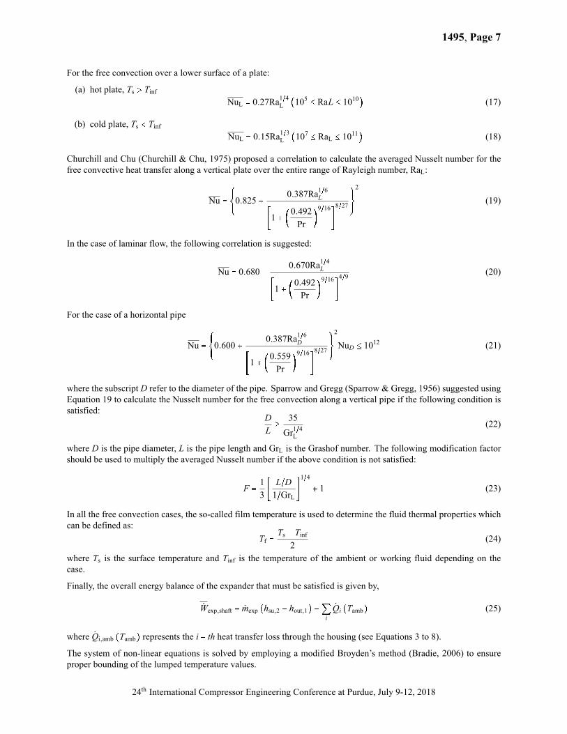
For the free convection over a lower surface of a plate:
(a) hot plate, Ts A TinfNuL � 0.27Ra1~4L �105 B RaL B 1010� (17)
(b) cold plate, Ts @ TinfNuL � 0.15Ra1~3L �107 B RaL B 1011� (18)
Churchill and Chu (Churchill & Chu, 1975) proposed a correlation to calculate the averaged Nusselt number for thefree convective heat transfer along a vertical plate over the entire range of Rayleigh number, RaL:
Nu �¢¦¤0.825 �
0.387Ra1~6L
�1 � �0.492Pr
�9~168~27
£§¥2
(19)
In the case of laminar flow, the following correlation is suggested:
Nu � 0.680 �0.670Ra1~4L
�1 � �0.492Pr
�9~164~9 (20)
For the case of a horizontal pipe
Nu �¢¦¤0.600 �
0.387Ra1~6D
�1 � �0.559Pr
�9~168~27
£§¥2
NuD B 1012 (21)
where the subscript D refer to the diameter of the pipe. Sparrow and Gregg (Sparrow & Gregg, 1956) suggested usingEquation 19 to calculate the Nusselt number for the free convection along a vertical pipe if the following condition issatisfied:
DLC
35Gr1~4L
(22)
where D is the pipe diameter, L is the pipe length and GrL is the Grashof number. The following modification factorshould be used to multiply the averaged Nusselt number if the above condition is not satisfied:
F �13� L~D1~GrL
1~4
� 1 (23)
In all the free convection cases, the so-called film temperature is used to determine the fluid thermal properties whichcan be defined as:
Tf �Ts � Tinf
2(24)
where Ts is the surface temperature and Tinf is the temperature of the ambient or working fluid depending on thecase.
Finally, the overall energy balance of the expander that must be satisfied is given by,
Wexp,shaft � mexp �hsu,2 � hout,1� �QiQi �Tamb� (25)
where Qi,amb �Tamb� represents the i � th heat transfer loss through the housing (see Equations 3 to 8).
The system of non-linear equations is solved by employing a modified Broyden’s method (Bradie, 2006) to ensureproper bounding of the lumped temperature values.
24th International Compressor Engineering Conference at Purdue, July 9-12, 2018
1495, Page 8
355 360 365 370 375 380Discharge Temperature
(meas) [K]
355
360
365
370
375
380
Dis
char
ge T
empe
ratu
re(c
alc)
[K]
±3 K
single-lump(MAE = 0.6%)multi-lump(MAE = 0.2%)
(a)
3 4 5 6 7 8Expander Pressure Ratio [-]
355
360
365
370
375
380
Dis
char
ge T
empe
ratu
re(c
alc)
[K]
measuredsingle-lumpmulti-lump
(b)
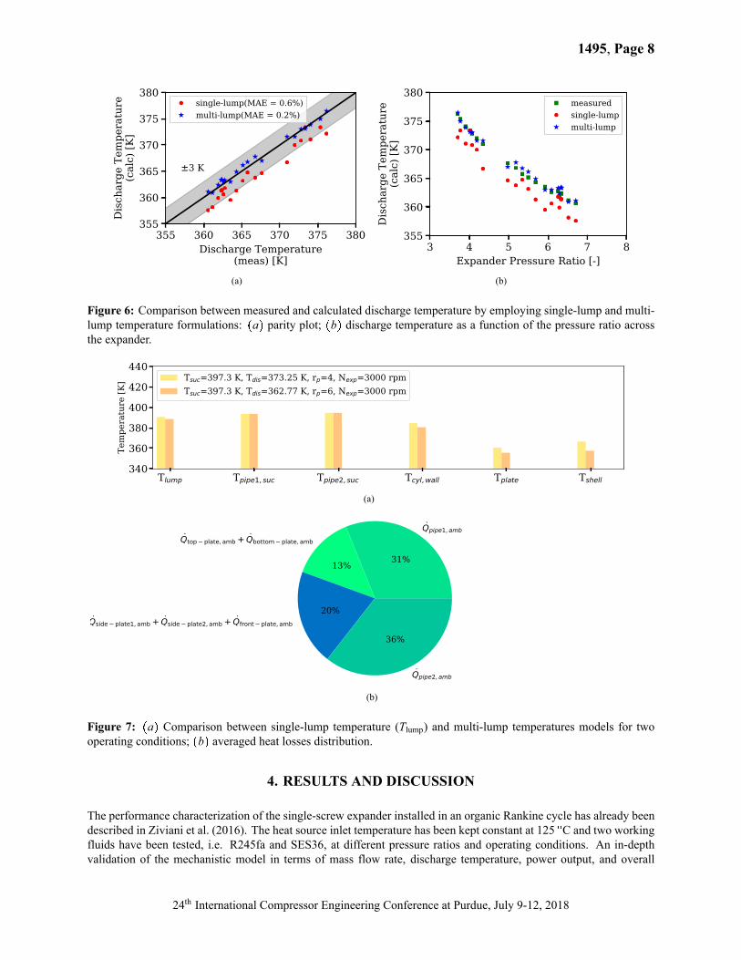
Figure 6: Comparison between measured and calculated discharge temperature by employing single-lump and multi-lump temperature formulations: �a� parity plot; �b� discharge temperature as a function of the pressure ratio acrossthe expander.
Tlump Tpipe1, suc Tpipe2, suc Tcyl, wall Tplate Tshell340
360
380
400
420
440
Tem
pera
ture
[K] Tsuc=397.3 K, Tdis=373.25 K, rp=4, Nexp=3000 rpm
Tsuc=397.3 K, Tdis=362.77 K, rp=6, Nexp=3000 rpm
(a)
Qpipe1, amb
31%
Qtop plate, amb + Qbottom plate, amb
13%
Qside plate1, amb + Qside plate2, amb + Qfront plate, amb
20%
Qpipe2, amb
36%
(b)
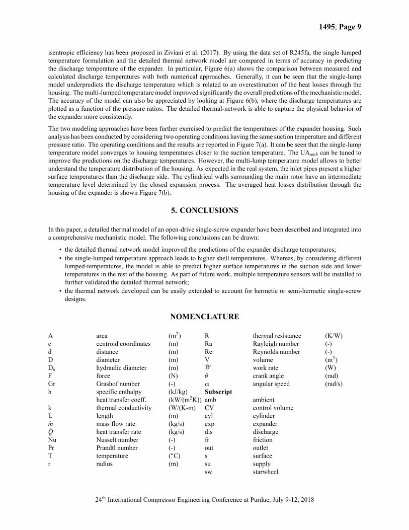
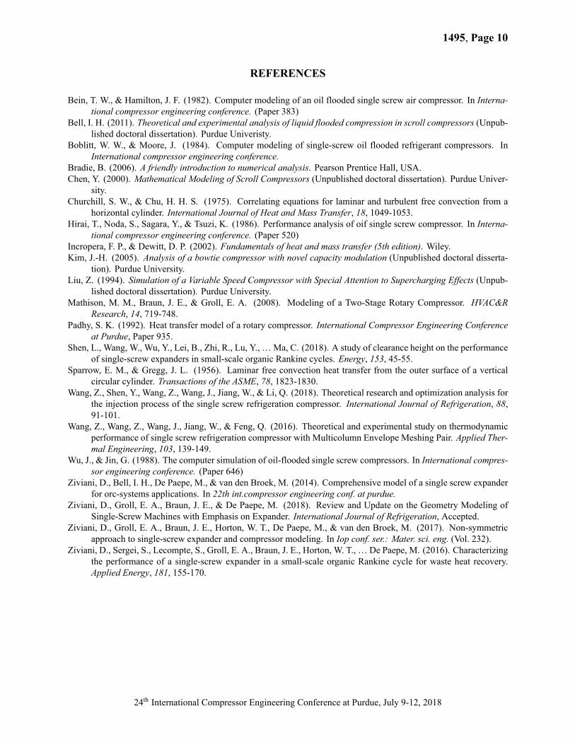
Figure 7: �a� Comparison between single-lump temperature (Tlump) and multi-lump temperatures models for twooperating conditions; �b� averaged heat losses distribution.
4. RESULTS AND DISCUSSION
The performance characterization of the single-screw expander installed in an organic Rankine cycle has already beendescribed in Ziviani et al. (2016). The heat source inlet temperature has been kept constant at 125 XC and two workingfluids have been tested, i.e. R245fa and SES36, at different pressure ratios and operating conditions. An in-depthvalidation of the mechanistic model in terms of mass flow rate, discharge temperature, power output, and overall
24th International Compressor Engineering Conference at Purdue, July 9-12, 2018
1495, Page 9
isentropic efficiency has been proposed in Ziviani et al. (2017). By using the data set of R245fa, the single-lumpedtemperature formulation and the detailed thermal network model are compared in terms of accuracy in predictingthe discharge temperature of the expander. In particular, Figure 6(a) shows the comparison between measured andcalculated discharge temperatures with both numerical approaches. Generally, it can be seen that the single-lumpmodel underpredicts the discharge temperature which is related to an overestimation of the heat losses through thehousing. Themulti-lumped temperaturemodel improved significantly the overall predictions of themechanistic model.The accuracy of the model can also be appreciated by looking at Figure 6(b), where the discharge temperatures areplotted as a function of the pressure ratios. The detailed thermal-network is able to capture the physical behavior ofthe expander more consistently.
The two modeling approaches have been further exercised to predict the temperatures of the expander housing. Suchanalysis has been conducted by considering two operating conditions having the same suction temperature and differentpressure ratio. The operating conditions and the results are reported in Figure 7(a). It can be seen that the single-lumptemperature model converges to housing temperatures closer to the suction temperature. The UAamb can be tuned toimprove the predictions on the discharge temperatures. However, the multi-lump temperature model allows to betterunderstand the temperature distribution of the housing. As expected in the real system, the inlet pipes present a highersurface temperatures than the discharge side. The cylindrical walls surrounding the main rotor have an intermediatetemperature level determined by the closed expansion process. The averaged heat losses distribution through thehousing of the expander is shown Figure 7(b).
5. CONCLUSIONS
In this paper, a detailed thermal model of an open-drive single-screw expander have been described and integrated intoa comprehensive mechanistic model. The following conclusions can be drawn:
• the detailed thermal network model improved the predictions of the expander discharge temperatures;• the single-lumped temperature approach leads to higher shell temperatures. Whereas, by considering differentlumped-temperatures, the model is able to predict higher surface temperatures in the suction side and lowertemperatures in the rest of the housing. As part of future work, multiple temperature sensors will be installed tofurther validated the detailed thermal network;
• the thermal network developed can be easily extended to account for hermetic or semi-hermetic single-screwdesigns.
NOMENCLATURE
A area (m2)c centroid coordinates (m)d distance (m)D diameter (m)Dh hydraulic diameter (m)F force (N)Gr Grashof number (-)h specific enthalpy (kJ/kg)
heat transfer coeff. (kW/(m2K))k thermal conductivity (W/(K-m)L length (m)m mass flow rate (kg/s)Q heat transfer rate (kg/s)Nu Nusselt number (-)Pr Prandtl number (-)T temperature (XC)r radius (m)
R thermal resistance (K/W)Ra Rayleigh number (-)Re Reynolds number (-)V volume (m3)W work rate (W)θ crank angle (rad)ω angular speed (rad/s)Subscriptamb ambientCV control volumecyl cylinderexp expanderdis dischargefr frictionout outlets surfacesu supplysw starwheel
24th International Compressor Engineering Conference at Purdue, July 9-12, 2018
1495, Page 10
REFERENCES
Bein, T. W., & Hamilton, J. F. (1982). Computer modeling of an oil flooded single screw air compressor. In Interna-tional compressor engineering conference. (Paper 383)
Bell, I. H. (2011). Theoretical and experimental analysis of liquid flooded compression in scroll compressors (Unpub-lished doctoral dissertation). Purdue Univeristy.
Boblitt, W. W., & Moore, J. (1984). Computer modeling of single-screw oil flooded refrigerant compressors. InInternational compressor engineering conference.
Bradie, B. (2006). A friendly introduction to numerical analysis. Pearson Prentice Hall, USA.Chen, Y. (2000). Mathematical Modeling of Scroll Compressors (Unpublished doctoral dissertation). Purdue Univer-
sity.Churchill, S. W., & Chu, H. H. S. (1975). Correlating equations for laminar and turbulent free convection from a
horizontal cylinder. International Journal of Heat and Mass Transfer, 18, 1049-1053.Hirai, T., Noda, S., Sagara, Y., & Tsuzi, K. (1986). Performance analysis of oif single screw compressor. In Interna-
tional compressor engineering conference. (Paper 520)Incropera, F. P., & Dewitt, D. P. (2002). Fundamentals of heat and mass transfer (5th edition). Wiley.Kim, J.-H. (2005). Analysis of a bowtie compressor with novel capacity modulation (Unpublished doctoral disserta-
tion). Purdue University.Liu, Z. (1994). Simulation of a Variable Speed Compressor with Special Attention to Supercharging Effects (Unpub-
lished doctoral dissertation). Purdue University.Mathison, M. M., Braun, J. E., & Groll, E. A. (2008). Modeling of a Two-Stage Rotary Compressor. HVAC&R
Research, 14, 719-748.Padhy, S. K. (1992). Heat transfer model of a rotary compressor. International Compressor Engineering Conference
at Purdue, Paper 935.Shen, L., Wang, W., Wu, Y., Lei, B., Zhi, R., Lu, Y., …Ma, C. (2018). A study of clearance height on the performance
of single-screw expanders in small-scale organic Rankine cycles. Energy, 153, 45-55.Sparrow, E. M., & Gregg, J. L. (1956). Laminar free convection heat transfer from the outer surface of a vertical
circular cylinder. Transactions of the ASME, 78, 1823-1830.Wang, Z., Shen, Y., Wang, Z., Wang, J., Jiang, W., & Li, Q. (2018). Theoretical research and optimization analysis for
the injection process of the single screw refrigeration compressor. International Journal of Refrigeration, 88,91-101.
Wang, Z., Wang, Z., Wang, J., Jiang, W., & Feng, Q. (2016). Theoretical and experimental study on thermodynamicperformance of single screw refrigeration compressor with Multicolumn Envelope Meshing Pair. Applied Ther-mal Engineering, 103, 139-149.
Wu, J., & Jin, G. (1988). The computer simulation of oil-flooded single screw compressors. In International compres-sor engineering conference. (Paper 646)
Ziviani, D., Bell, I. H., De Paepe, M., & van den Broek, M. (2014). Comprehensive model of a single screw expanderfor orc-systems applications. In 22th int.compressor engineering conf. at purdue.
Ziviani, D., Groll, E. A., Braun, J. E., & De Paepe, M. (2018). Review and Update on the Geometry Modeling ofSingle-Screw Machines with Emphasis on Expander. International Journal of Refrigeration, Accepted.
Ziviani, D., Groll, E. A., Braun, J. E., Horton, W. T., De Paepe, M., & van den Broek, M. (2017). Non-symmetricapproach to single-screw expander and compressor modeling. In Iop conf. ser.: Mater. sci. eng. (Vol. 232).
Ziviani, D., Sergei, S., Lecompte, S., Groll, E. A., Braun, J. E., Horton, W. T., … De Paepe, M. (2016). Characterizingthe performance of a single-screw expander in a small-scale organic Rankine cycle for waste heat recovery.Applied Energy, 181, 155-170.
24th International Compressor Engineering Conference at Purdue, July 9-12, 2018